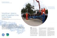
Capital drilling equipment - GE Energy
Capital drilling equipment - GE Energy
Capital drilling equipment - GE Energy

You also want an ePaper? Increase the reach of your titles
YUMPU automatically turns print PDFs into web optimized ePapers that Google loves.
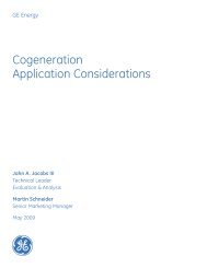
<strong>Capital</strong> <strong>drilling</strong> <strong>equipment</strong><br />
Advanced, field-proven risers, diverters and connectors
2<br />
<strong>Capital</strong> <strong>drilling</strong> <strong>equipment</strong><br />
VetcoGray, a <strong>GE</strong> Oil & Gas business, has been building<br />
its reputation as a highly skilled and experienced supplier<br />
of <strong>drilling</strong> <strong>equipment</strong> to the oil and gas industry since<br />
1906, when Regan Forge began manufacturing crown<br />
blocks and travelling blocks for the California exploration<br />
market. Today, we are one of the world’s leading suppliers<br />
of marine <strong>drilling</strong> riser systems. Our legacy of technology<br />
development and innovative solutions puts us in the<br />
forefront of offshore<strong>drilling</strong>, especially for deepwater<br />
exploration. VetcoGray supplied the complete <strong>drilling</strong><br />
riser system for the world’s first, and to date, only,<br />
exploration well in water depths greater than 10,000 ft.<br />
We provide a complete line of capital <strong>drilling</strong> <strong>equipment</strong><br />
for jackup and floating rig <strong>drilling</strong> applications.<br />
Diverters for floating <strong>drilling</strong> units<br />
KFDS . . . . . . . . . . . . . . . . . . . . . . . . . . . . . . . . . . . . . . . . . . . . . . . . 4<br />
CSO: Complete Shut-Off . . . . . . . . . . . . . . . . . . . . . . . . . . . . . . 4<br />
Diverters for jackup and platform <strong>drilling</strong> units<br />
KFDJ . . . . . . . . . . . . . . . . . . . . . . . . . . . . . . . . . . . . . . . . . . . . . . . . . 5<br />
KFDJ model “J” . . . . . . . . . . . . . . . . . . . . . . . . . . . . . . . . . . . . . . . 6<br />
Drilling riser system components<br />
Telescopic joint . . . . . . . . . . . . . . . . . . . . . . . . . . . . . . . . . . . . . . 8<br />
Tension rings<br />
KT . . . . . . . . . . . . . . . . . . . . . . . . . . . . . . . . . . . . . . . . . . . . . . . 9<br />
SDL/SLS . . . . . . . . . . . . . . . . . . . . . . . . . . . . . . . . . . . . . . . . 10<br />
SDC . . . . . . . . . . . . . . . . . . . . . . . . . . . . . . . . . . . . . . . . . . . . . 12<br />
Marine <strong>drilling</strong> riser<br />
MR-6H SE riser . . . . . . . . . . . . . . . . . . . . . . . . . . . . . . . . . . . 14<br />
MR-6H SE riser adapter . . . . . . . . . . . . . . . . . . . . . . . . . 15<br />
MR-6E riser. . . . . . . . . . . . . . . . . . . . . . . . . . . . . . . . . . . . . . 16<br />
HMF riser . . . . . . . . . . . . . . . . . . . . . . . . . . . . . . . . . . . . . . . 17<br />
Ancillary riser <strong>equipment</strong><br />
Marine riser handling spiders . . . . . . . . . . . . . . . . . . . . 18<br />
Gimbal . . . . . . . . . . . . . . . . . . . . . . . . . . . . . . . . . . . . . . . . . . 18<br />
Single flex joint . . . . . . . . . . . . . . . . . . . . . . . . . . . . . . . . . 19<br />
Intermediate flex joint . . . . . . . . . . . . . . . . . . . . . . . . . . 19<br />
Subsea connectors<br />
H-4 hydraulic subsea connectors<br />
E H-4 . . . . . . . . . . . . . . . . . . . . . . . . . . . . . . . . . . . . . . . . . . . 20<br />
ExF H-4 . . . . . . . . . . . . . . . . . . . . . . . . . . . . . . . . . . . . . . . . . 20<br />
ExF HAR . . . . . . . . . . . . . . . . . . . . . . . . . . . . . . . . . . . . . . . 20<br />
DWHD H-4 . . . . . . . . . . . . . . . . . . . . . . . . . . . . . . . . . . . . . 20<br />
SHD H-4 . . . . . . . . . . . . . . . . . . . . . . . . . . . . . . . . . . . . . . . 21<br />
VX-2 ® , VGX-2 ® and VT-2 ® gaskets . . . . . . . . . . . . . . . . . . . . 22<br />
Aftermarket support<br />
Riser Inspection (RADAR) . . . . . . . . . . . . . . . . . . . . . . . . . . . . 24<br />
Corporate overview . . . . . . . . . . . . . . . . . . . . . . . . . . . . . . . . 26<br />
3
KFDS diverter<br />
VetcoGray is one of the market leaders for diverter systems<br />
in the offshore <strong>drilling</strong> market. We are a single-source<br />
supplier for complete systems including diverter assembly,<br />
controls and valves. An integrated package, engineered<br />
to specific requirements, provides maximum safety, efficiency<br />
and savings. For 25 years, VetcoGray has provided KFDS<br />
diverter technology with field-proven protection from shallow<br />
gas blowouts.<br />
CSO diverter<br />
The CSO (Complete Shut-off) Diverter is used on floating<br />
<strong>drilling</strong> rigs to divert shallow gas overboard prior to<br />
installation of the BOP. Once the BOP has been installed<br />
the diverter is used to vent gas in the riser, above the<br />
BOP. The CSO model can seal on either drill pipe or an<br />
open hole.<br />
Features and benefits<br />
• Housing accommodates large diameter riser buoyancy<br />
modules<br />
• Complete open-hole shut-off with 20" through-bore<br />
• 15 - 10 second closure time on pipe or open hole<br />
• 500 psi rated system<br />
• Control system maximum operating pressure of 1,500 psi<br />
• High capacity systems available for supporting the riser<br />
string from the diverter housing in emergency hangoff<br />
situations<br />
• Connection block enables hydraulic operating functions<br />
to be quickly attached or disconnected<br />
• Standard housing holds multiple outlets, up to 20"<br />
diameter<br />
4<br />
Dimensional data: CSO diverter<br />
Outlet nom.<br />
(in.)<br />
All dimensions in inches. * Number and size of outlets are optional.<br />
Diverters for floating <strong>drilling</strong> units Diverters for jackup and platform <strong>drilling</strong> units<br />
Features and benefits<br />
• Diverter support housing, overboard lines and<br />
associated valving are permanently installed on<br />
the rig structure<br />
• Diverter assembly is run and retrieved through<br />
the rotary table with the marine riser<br />
• Variable outlet sizes and orientations can accommodate<br />
virtually any rig design<br />
• Valving is external, allowing for rig design variation<br />
and valve/actuator preferences<br />
Diverter Assembly<br />
B<br />
C<br />
Standard Housing Has<br />
Multiple Outlets, Up To<br />
20” Diameter<br />
24.25”<br />
Flex Joint<br />
Crossover Flange<br />
Running Tool Profile<br />
Spherical Element<br />
A B C D E<br />
12 11.38 16.38 15.38 43.75 71.50<br />
14 12.50 17.00 16.00 45.00 72.75<br />
16 14.31 18.00 17.00 47.00 74.75<br />
18 16.50 19.00 18.00 49.00 76.75<br />
20 18.38 20.00 19.00 51.00 78.75<br />
A<br />
Pressure Energized<br />
Flow Line Seals<br />
D<br />
Diverter<br />
Support Housing<br />
E<br />
KFDJ diverter<br />
The KFDJ diverter system is used on platforms and jackup<br />
rigs to protect against shallow gas kicks during <strong>drilling</strong><br />
operations. In the event of a shallow gas kick, the diverter<br />
is energized to seal around the drill pipe and divert the<br />
gas safely overboard.<br />
Features and benefits<br />
• Complete protection while running casing strings and<br />
<strong>drilling</strong> hole is provided by a full range of insert packer<br />
sizes, all of which use a “J” type running tool<br />
• Available with a rotating insert which provides low<br />
pressure packoff on the kelly or drill pipe during <strong>drilling</strong><br />
• Fixed support housing, a proprietary feature, is<br />
securely bolted to the rotary beams and provides fixed<br />
outlets for flowline, fill-up line and vent lines<br />
G<br />
Flowline Vent<br />
Outlets<br />
F Rotary<br />
Support<br />
Structure<br />
Flowline<br />
Seals<br />
Locking<br />
Dogs<br />
Overshot<br />
Spool<br />
Rotary Table<br />
A<br />
All dimensions in inches. * Number and size of outlets are optional.<br />
B<br />
C<br />
D<br />
Diverter<br />
Assembly<br />
Insert<br />
Packer<br />
Fill Up<br />
Line<br />
Support<br />
Housing<br />
EC-6<br />
Coupling<br />
E<br />
Retainer<br />
Bolts<br />
Dimensional data: CSO diverter standard hookup KFDJ<br />
Rotary<br />
table<br />
• Support housing allows installation of outlets up to 20”<br />
diameter to virtually any configuration<br />
• Diverter, spacer spool and overshot packer assembly may<br />
be pulled or run without connecting or disconnecting the<br />
flowline, fill-up line and vent lines<br />
• Mudline suspension hangers and bit sizes up to 27.41”<br />
for 37-1/2” rotaries or 36.41” for 49-1/2” rotaries can<br />
be run without removing the diverter assembly<br />
• Diverter, spacer spool and overshot packer each fit<br />
through a 37-1/2” rotary table. Minimum bore through<br />
the standard support housing is 36-1/2” ID for the 37-1/2”<br />
in rotary installation. Optional 37-1/2” bore is available<br />
• Overshot packer on the bottom of the diverter spacer<br />
spool assembly reduces the nipple-up time normally<br />
required to weld flanges or hubs to casing<br />
KFDJ diverter<br />
A B C D E F G<br />
37.50 42.50 37.25 37.25 37.25 37.25 37.25 37.25<br />
49.50 53.00 49.25 49.25 49.25 49.25 49.25 49.25<br />
5
6<br />
KFDJ model “J” diverter<br />
Diverters for jackup and platform <strong>drilling</strong> units Diverters for jackup and platform <strong>drilling</strong> units<br />
Designed with all the field proven features of the standard<br />
KFDJ diverter, but with fewer hydraulic connections,<br />
VetcoGray’s KFDJ model “J” diverter system has a “J” lock<br />
between the diverter and the support housing.<br />
A<br />
F<br />
Rotary<br />
Table<br />
Locking Mechanism<br />
D<br />
(Diverter)<br />
B<br />
(Housing)<br />
All dimensions in inches. * Number and size of outlets are optional.<br />
C<br />
Rotary<br />
Beams<br />
E<br />
KFDJ model “J” diverter<br />
Dimensional data: standard hookup KDFJ “J” with 12” nominal outlets*<br />
Rotary<br />
table<br />
A B C D E F<br />
37.50 78.50 36.50 27.50 36.25 35.25 15.62<br />
49.50 73.25 47.00 27.50 46.75 35.25 10.40<br />
49.50 96.50 47.00 36.50 46.75 35.25 29.40<br />
Features and benefits<br />
• Simplified design<br />
• Only three hydraulic functions: energizing/venting the<br />
diverter packing, the flowline seals, and the overshot<br />
packer<br />
• "J" slots in the support housing align the diverter<br />
outlets with the housing outlets<br />
• A mechanical latch secures the diverter in the housing<br />
and provides a visual indicator of lock engagement<br />
• All components of the support housing and the diverter<br />
assembly area feature heavy wall construction for<br />
pressure containment and erosion protection during<br />
high velocity, multi-phase flow<br />
• Insert packers are available in a full range of sizes<br />
• Custom designed for specific applications<br />
Newly installed KFDJ diverter<br />
Diverter Insert<br />
Diverter Support Housing
Telescopic joint<br />
The telescopic joint compensates for heave and offset of<br />
the vessel and is available for all riser systems. This movement<br />
is achieved through the stroking movement of the<br />
inner and outer barrel of the telescopic joint.<br />
Features and benefits<br />
• Available for MR-6E, MR-6H SE, and HMF riser<br />
systems<br />
• Maximum rated riser tensile load capacity<br />
in locked position<br />
• Hydraulic latch release for inner and outer<br />
barrels available<br />
• Dual split/solid packer elements<br />
• Fixed or rotating integral tension rings<br />
• Prepped for non-integral SDL, SDC and<br />
KT tension rings<br />
• Fluid or roller bearing prep<br />
Telescopic joint<br />
Drilling riser system components Drilling riser system components<br />
Tension rings<br />
The tension ring attaches to the telescopic joint and forms<br />
a termination point between the riser system and the tensioning<br />
system on a floating rig. It is used to pull and support tension<br />
to give the riser string more stability. VetcoGray designs<br />
and manufactures a variety of tension rings.<br />
KT tension ring<br />
Features and benefits<br />
• Combines the functionality of a tension ring and the<br />
termination joint<br />
• Simplifies running and retrieving the marine riser by<br />
eliminating makeup/breakout of tensioner lines and<br />
hydraulic hoses in the moon pool area<br />
• Choke, kill and auxiliary line terminations are<br />
permanently connected<br />
• Orientation pins engage slots in the telescopic joint<br />
line termination housing for easy makeup<br />
• Permanently installed tensioner lines maintain proper<br />
orientation with rig <strong>drilling</strong> tensioners<br />
• Riser tensioner lines remain attached to the KT ring<br />
• Thrust and radial bearings permit rotation of the<br />
vessel relative to the riser string<br />
• Optional fluid bearings minimize breakout torque<br />
• Auxiliary line pins have differential seal areas to<br />
ensure fail-safe engagement<br />
KT tension ring<br />
KT tension ring<br />
8 9
SDL/SLS tension ring<br />
Features and benefits<br />
Similarities between SDL and SLS rings<br />
• Riser tensioner lines remain attached to the SDL/SLS<br />
ring so riser tensioner lines are properly spaced at<br />
all times<br />
• Both rings use pad eyes for connection with the<br />
tensioner lines<br />
• When not in use, the rings lock and store to a mating<br />
profile on the bottom of the diverter support housing<br />
for convenient and orderly storage<br />
• Telescopic joint is run and pulled through the rotary<br />
table without disconnecting the tensioner lines from<br />
the SDL/SLS ring<br />
• Hydraulic piping for lockdown/storage dogs remains<br />
permanently connected<br />
Drilling riser system components Drilling riser system components<br />
Differences between SDL and SLS rings<br />
• SDL ring utilizes a gear-driven dog load interface with<br />
the telescopic joint<br />
• SDL rings do not have a fluid bearing; it is integral with<br />
the telescopic joint for this configuration<br />
• SLS rings utilize a load-shoulder interface with the<br />
telescopic joint<br />
• SLS rings have an integral fluid bearing<br />
SDL Tension Support Ring<br />
VetcoGray’s tension rings are proven to perform in the<br />
harsh environments of deepwater <strong>drilling</strong><br />
SDL tension support ring with optional fluid or roller bearing<br />
Convenient and<br />
orderly storage
SDC tension ring<br />
Features and benefits<br />
• SDC rings utilize a ball-joint connection with directline<br />
cylinder tensioners<br />
• Direct-line cylinders are permanently attached to the<br />
SDC ring for fast and safe attachment to the<br />
telescopic joint<br />
• A hinged split-ring design opens and closes around<br />
the telescopic joint<br />
• Designed to be opened and moved out of the way<br />
for storage while the tensioning cylinders remain<br />
attached<br />
• Optional KT-style termination ring can be utilized<br />
with the SDC tension ring<br />
12<br />
Drilling riser system components Drilling riser system components<br />
Quick, efficient<br />
make-up<br />
SDC tension ring<br />
SDC tension ring with KT style termination ring<br />
SDC tension ring - open SDC tension ring - closed<br />
13
Marine <strong>drilling</strong> riser<br />
The marine <strong>drilling</strong> riser connects the floating rig to the<br />
subsea wellhead. The subsea well is drilled through the<br />
riser allowing the <strong>drilling</strong> mud to circulate back up to the<br />
rig. VetcoGray offers three main types of marine <strong>drilling</strong><br />
riser.<br />
MR-6H SE riser<br />
This fully-automated make-up, 3.5 million pound rated<br />
(API class 'H') is the latest offering from VetcoGray. The<br />
design is simple, with very few parts, utilizing field proven<br />
concepts and profiles which have provided many years of<br />
exemplary service. The highly preloaded coupling with<br />
efficient load path also provides the option for incorporation<br />
of a metal seal if required for higher-pressure conditions.<br />
The modularized, hydraulically operated handling<br />
spider provides all mechanisms required for make-up and<br />
break-out of the coupling which minimizes intervention of<br />
rig floor personnel. The spider design allows quick change<br />
out of key subassemblies during riser running operations.<br />
Features and benefits<br />
• Automated make-up with minimal personnel intervention<br />
• Utilizes reliable, field proven concepts and profiles<br />
(H-4 & MR)<br />
• High preload / efficient load path<br />
• Easy to replace parts subject to wear<br />
• Easy maintenance, service and inspection with all<br />
critical areas readily accessible<br />
• External surfaces of pin and box can be fully<br />
“TSA protected”<br />
• Handling spider modularized to allow quick change<br />
out of critical parts or subassemblies<br />
14<br />
Drilling riser system components Drilling riser system components<br />
MR-6H SE profile<br />
MR-6H SE assembled<br />
MR-6H SE exploded view<br />
MR-6H SE riser adapter<br />
This new riser adapter was created using the same technology<br />
as the MR-6H SE riser coupling; however, it is selfcontained<br />
and designed to be run without a spider. The<br />
adapter was created to improve safety during the operation<br />
of making-up the connection between the top of the<br />
LMRP and the first joint of riser. Current flange designs<br />
require personnel to be suspended over the stack and<br />
moon pool while making-up the connection. This is a<br />
potentially hazardous, time consuming process. In contrast,<br />
the new MR-6H SE riser adapter can be quickly connected<br />
and released from a safe distance.<br />
Features and benefits<br />
Safety<br />
• Eliminates the potential hazards of riser adapter<br />
make-up and break out<br />
• Eliminates the need to lower heavy tools, bolts and<br />
<strong>equipment</strong> to personnel<br />
• Reduces need for multiple rig personnel to make this<br />
connection<br />
• Existing rig designs have limited clearance to make up<br />
the riser adapter. With the MR-6H SE riser adapter, this<br />
clearance restriction is no longer an issue<br />
Efficiency<br />
• Significantly reduces the time to make/break<br />
the connection.<br />
• Utilizes field proven technology (H-4<br />
connector and dog style riser)<br />
View of MR-6H SE riser adapter<br />
15
MR-6E riser<br />
The MR-6E is a dog style riser connection. To make the<br />
connection, the dogs in the box are driven into the profile<br />
in the pin, making a fully preloaded connection.<br />
The design provides an improved and increased resistance<br />
to high tensile loads and large bending moments, conditions<br />
common with today’s deepwater <strong>drilling</strong> operations.<br />
The MR-6E is lightweight, simple to operate and fast to run.<br />
16<br />
Drilling riser system components Drilling riser system components<br />
Features and benefits<br />
• 2 million lb. rating per API 16R Class E<br />
• Low make-up torque, 950 ft - lbs<br />
• Simple, light weight design<br />
• MR-6E couplings can be used interchangeably<br />
with MR-6D couplings<br />
MR-6E riser coupling specifi cations 5” C & K, 4-1/2” Boost, & 2-7/8” Hydraulic stab subs<br />
O.D. (1) I.D. (2) Length Weight (3)<br />
No. of activating<br />
screws<br />
Torque<br />
41.125” 19.75” 23.125” 2,510 lbs 6 950 ft.-lbs.<br />
(1) Does not include buoyancy material (2) I.D. based on 0.625" wall thickness of principal tube (3) Includes weight of auxiliary line stab subs<br />
HMF riser<br />
One of the most reliable and advanced marine riser systems<br />
in today’s market is VetcoGray’s HMF system. Developed<br />
through extensive design analysis and test programs of<br />
bending, tension, internal pressure and functional evaluations,<br />
this coupling is ideal for deep water applications<br />
where high load operating conditions exist. The HMF riser<br />
coupling has been field proven through many years of<br />
worldwide use, including <strong>drilling</strong> the current water depth<br />
well record of 10,011 feet in the Gulf of Mexico.<br />
Features and benefits<br />
• Meets API 16R, class D, E, F, G, H and J<br />
• Stepped diameter design of pin and box simplifies<br />
engagement, even with severe vessel movement<br />
• Ideal for deep water applications where high load<br />
operating conditions exist<br />
• No loose parts, all bolts and inserts stay in the<br />
pin/box flanges preventing bolt loss and potential<br />
thread damage<br />
• Field removable and replaceable nose ring<br />
• Locking bolts preloaded above the rated coupling<br />
loads, which extends the fatigue life of the riser coupling<br />
• Hydraulic running/test tool facilitates quicker riser<br />
running times<br />
• Field replaceable choke and kill line stab subs<br />
View of Class F, HMF riser flange pin<br />
View of Class F, HMF riser flange pin<br />
Class F, HMF flange riser<br />
17
Marine riser handling spider<br />
The spider is used to support the riser string while the connections are being made or broken while the riser string is<br />
being run or retrieved. VetcoGray makes a variety of styles, each compatible with specific types of riser connections.<br />
MR-6E hydraulic spider<br />
This spider is used to support the MR-6E riser system. The<br />
hydraulic support dogs extend to support the lower flange<br />
of the coupling while the connection is either made or broken.<br />
MR-6H SE spider<br />
The MR-6H SE riser handling spider supports the riser string<br />
on hydraulic sliding dogs. Six hydraulic units move the cam<br />
ring up and down to make or break the connector.<br />
18<br />
MR-6H SE coupling with spider<br />
Ancillary riser <strong>equipment</strong> Ancillary riser <strong>equipment</strong><br />
MR-6E hydraulic spider<br />
HMF spider<br />
The HMF hydraulic-gate riser handling spider is used when<br />
running or retrieving HMF riser joints through the rotary table.<br />
Split gates, operated by hydraulic cylinders, support the riser<br />
string when the gates are in the closed and locked position.<br />
Gimbal<br />
HMF spider<br />
The gimbal sits under the spider and acts as a shock<br />
absorber to assist with the weight of the riser string. It<br />
can also compensate for up to 6 degrees of offset while<br />
running or retrieving the riser string.<br />
Single flex joint<br />
The single flex joint is installed in the Lower Marine<br />
Riser Package (LMRP). It allows angular deflection up to<br />
10 degrees in the lower portion of the riser string. The<br />
combination of an elastomeric bearing and a seal unit<br />
give it flexibility and the capacity for internal pressure<br />
containment of up to 3,000 psi.<br />
Features and benefits<br />
• Installed in the LMRP below the riser/BOP stack interface<br />
• Uses a combination elastomeric bearing and seal unit<br />
to eliminate the need for a pressure balanced ball and<br />
socket interface with seals<br />
• Up to 2 million lb tensile load capacity<br />
• Rated for H2S service and oil-based <strong>drilling</strong> mud<br />
• Angular deflection to 10 degrees on either side of its<br />
axial center while subjected to tensile loading and<br />
internal pressures up to 3,000 psi<br />
• Pressure balance and lubrication systems not required<br />
Intermediate flex joint<br />
The intermediate flex joint is installed below the<br />
telescopic joint and allows for angular deflection<br />
up to 20 degrees in the top portion of the riser string.<br />
Features and benefits<br />
• Installed below the telescopic joint<br />
• Up to 2.5 million lb tensile load capacity<br />
• Angular deflection to 20 degrees on either side of its<br />
axial center while subjected to tensile loading and<br />
internal pressure of 1,500 psi<br />
Single flex joint<br />
Intermediate flex joint leaving VetcoGray's facility<br />
19
H-4 ® hydraulic subsea connector family<br />
The H-4 family of subsea connectors, introduced in 1964, are<br />
in use in every major producing region of the world and in<br />
every type of offshore environment. The VetcoGray family<br />
of H-4 connectors are field proven, hydraulically operated,<br />
metal-to-metal sealing connectors that are widely used for:<br />
• BOP stack to wellhead<br />
• LMRP to BOP stack<br />
• Completion tree to wellhead<br />
• TLP/subsea template tieback<br />
• Production riser assembly to subsea manifold<br />
• Single point mooring to anchor base<br />
• Caisson completions and artificial island <strong>drilling</strong><br />
• Specially adapted applications<br />
Ideal for deepwater use, the H-4 line of connectors has reliable,<br />
simple operating characteristics; excellent bending and tensile<br />
load capabilities; and a long, economical service life.<br />
Features and benefits<br />
Field proven reliability<br />
• In service since 1964<br />
High strength connection<br />
• 355 degrees circumferential dog ring contact to the<br />
four locking grooves of the wellhead/mandrel profile<br />
distributes bending and tensile loads uniformly<br />
Primary and secondary hydraulic circuits<br />
• The dual hydraulic operating system generates 25%<br />
more releasing force than locking force<br />
Passive mechanical release<br />
• Dog profile design (45 degrees) assures passive<br />
retraction of locking dog segments with overpull<br />
Visual position indicator rod<br />
• Indicator rod provides positive, visual indication of<br />
locked and unlocked position as well as cam ring travel<br />
• Rig serviceable hydraulic systems<br />
VX/VT back-up seal profile<br />
• All current H-4 connector designs have the VX/VT<br />
seal profile, and have Inconel inlay for corrosion and<br />
damage protection<br />
20<br />
Subsea connectors Subsea connectors<br />
E H-4 connector E x F H-4 connector E x F HAR H-4 connector DW HD H-4 connector<br />
Easy primary seal replacement<br />
• Primary VX/VT seal is ROV replaceable and retrievable<br />
Hydrate protection<br />
• Hydrate seals between the connector and the high<br />
pressure wellhead housing are standard<br />
Flush ports<br />
• In the event that hydrates form in the H-4 connector,<br />
hydrate flushing ports located in the upper body will<br />
facilitate their removal<br />
Seal ring protection<br />
• Connector to wellhead/mandrel interface is selfaligning,<br />
which assures that the gasket will not be<br />
damaged during makeup<br />
Safety<br />
• Replacement of seal ring does not require personnel<br />
to be under connector/BOP<br />
Pressure-tight self-energizing seal<br />
• Positive compression loading of the seal ring into the<br />
corrosion and damage resistant seal surface profile<br />
provides reliable sealing integrity<br />
• Optional upper body configurations available<br />
• Individual hydraulic pistons provide multiple circuits<br />
Bore Pressure (ksi)<br />
SHD H-4 hydraulic subsea connector<br />
The SHD H-4 connector (Super Heavy Duty) is the latest<br />
member of the H-4 family. This connector, designed for<br />
use with the MS 700 and SMS 700 wellheads, has exceptional<br />
bending load capacities and fatigue life characteristics. It<br />
is ideal for deepwater, critical service where high bending<br />
loads are anticipated.<br />
SHD H-4 connector<br />
18-3/4” SHD H-4 load capacity envelope<br />
Load capacity at 2/3 yield<br />
Note: Tension values at the wellhead for 3,000 psi connector locking pressure.<br />
25<br />
20<br />
15<br />
10<br />
5<br />
tension - 1,500 kips<br />
tension - 0 kips<br />
capacity envelope<br />
0<br />
0 1.0 2.0 3.0 4.0 5.0 6.0 7.0 8.0<br />
Bending moment (MM ft-lbs)<br />
SHD H-4 connector specifi cations<br />
Maximum service pressure<br />
15,000<br />
psi<br />
Number of hydraulic cylinders total 10<br />
Number of hydraulic cylinders primary 5<br />
Number of hydraulic cylinders secondary 5<br />
Cylinder lock area 626.35 sq in<br />
Cylinder unlock area 785.4 sq in<br />
Lock fl uid volume total 12.10 US Gal<br />
Unlock fl uid volume total 12.10 US Gal<br />
Maximum hydraulic operational pressure 15.10 US Gal<br />
Maximum hydraulic testing pressure 3,000 psi<br />
SHD H-4 connector specifi cations 5,000 psi<br />
Connector wellhead preload<br />
1,500 psi Lock 3.75 x 10 6 lb<br />
3,000 psi Lock 7.50 x 10 6 lb<br />
Maximum OD 66 in<br />
Weight based on studded top 28,600 lbs<br />
Swallow 32.25 in<br />
21
VX-2 ® , VGX-2 ® and VT-2 ® gaskets<br />
VX-2, VGX-2 and VT-2 gaskets are designed<br />
to seal internal pressure in H-4 connectors<br />
The stainless steel VX-2 gasket is the standard gasket for<br />
<strong>drilling</strong> and production; it is rated for 15,000 psi internal<br />
pressure, 250 degrees F, and is manufactured from corrosion<br />
resistant material.<br />
The carbon steel VX-2 gasket is a lower cost/lower<br />
performance version. It is rated for 10,000 psi internal<br />
pressure, 250 degrees F, and is coated for corrosion<br />
resistance.<br />
The VGX-2 gasket is a higher performance/higher cost<br />
version. It is rated for 15,000 psi internal pressure, 350<br />
degrees F, and is manufactured from high yield strength<br />
stainless steel with a silver coating. The higher yield<br />
22<br />
Subsea connectors Subsea connectors<br />
2 seal bands 2 seal bands Radius 0.25”<br />
strength material provides a large range of elastic action,<br />
while the silver coating provides resistance to galling. The<br />
coefficient of thermal expansion of the gasket approximates<br />
that of the wellhead and the H-4 upper body.<br />
The VT-2 gasket seals on a secondary independent seal<br />
surface and is used when the primary VX sealing surface<br />
is damaged. It is rated for 15,000 psi internal pressure,<br />
250 degrees F, and is manufactured from corrosion<br />
resistant material.<br />
Other API sizes and optional configurations are available.<br />
Insert options include Hycar, lead, and tin indium materials.<br />
VX-2, VGX-2 and VT-2 gaskets<br />
VX-2 gasket<br />
MS-700 wellhead with VX-2 gasket prior to makeup with<br />
H-4 connector<br />
Dimensional data: VX-2, VGX-2 and VT-2 gaskets<br />
Working<br />
pressure (psi)<br />
Temperature<br />
range (ºF)<br />
External pressure<br />
rating (psi)<br />
Seal material<br />
VX-2 gasket<br />
(gas/liquid)<br />
VX-2 gasket<br />
(gas/liquid)<br />
MS-700 wellhead and H-4 connector in test fixture<br />
VT-2 gasket<br />
(gas/liquid)<br />
VGX-2 gasket<br />
(gas/liquid)<br />
15,000 10,000 15,000 15,000<br />
35 - 250 35 - 250 35 - 250 35 - 350<br />
1,000 2,500 1,000 3,500<br />
Stainless steel<br />
(316)<br />
Mild steel<br />
Stainless steel<br />
(316)<br />
Stainless steel /<br />
Corrosion<br />
resistant alloy<br />
Surface coating Moly based Moly based Moly based Moly based<br />
PSL-4 qualifi cations yes yes yes yes<br />
23
RADAR - Riser Active Data<br />
Acquisition Recorder<br />
RADAR was developed to address the need for an efficient,<br />
safe and cost-effective method of internal inspection of <strong>drilling</strong><br />
and production risers, choke and kill lines, and other metal<br />
pipes.<br />
Features and benefits<br />
• Uses real-time data acquisition and analysis to<br />
enable <strong>drilling</strong> contractors to monitor life-cycle<br />
wear measurements of <strong>drilling</strong> riser components<br />
• Helps minimize risk by identifying marginal <strong>equipment</strong><br />
• Plan for regular repairs, maintenance and part replace<br />
ment to avoid costly rig shutdowns<br />
Inspection data for specific risers can be stored digitally for<br />
easy retrieval and used to track riser assets by serial number<br />
to facilitate their transfer between rigs and regions.<br />
24<br />
Aftermarket support Aftermarket support<br />
RADAR tools and procedures have been witnessed and<br />
certified by DNV.<br />
RADAR is a tool for data acquisition and analysis that performs<br />
extensive data processing to:<br />
• Identify defects based on specific rejection criteria<br />
• Determine location, orientation, type and size of<br />
reportable flaws<br />
• Present the data in a meaningful display<br />
• Video record the internal portion of the pipe<br />
• Identify defects based on specific rejection criteria<br />
Weld quality inspection<br />
• Two time-of-flight-diffraction (TOFD) channels for inspection<br />
of the entire weld volume along the length of the<br />
weld<br />
• Four pulse-echo shear wave transducers in a 4-channel<br />
setup to analyze the root and cap regions of the weld<br />
Convenient riser<br />
inspection on your rig<br />
Inspections can be performed almost anywhere, even on a drillship in transit<br />
Pipe thickness inspection<br />
• Four pulse-echo longitudinal wave transducers in a<br />
4-channel setup spaced at 90 degrees apart for<br />
increased data acquisition speeds<br />
Video record<br />
• Video record of internal condition of riser body tube<br />
Analysis programs complement the data acquisition system<br />
and operate on the same computer platform. The processed<br />
data are displayed in two presentations.<br />
Color thickness map<br />
• Ultrasonic data is displayed in various colors as a<br />
function of the depth and position along the length<br />
and circumference of the riser<br />
B-Scan display<br />
• Enables the operator to use critical Rf waveform data<br />
and the B-Scan images created from these waveforms<br />
to accurately identify and assess flaws<br />
Reporting criteria can be customized to each particular<br />
application, following industry standards, or alternative<br />
criteria based on fit-for-purpose analysis.<br />
An internal inspection with RADAR has the primary advantage<br />
that it eliminates all special handling, stripping or external<br />
preparation of the pipe. The inspection itself is performed<br />
in a third of the time required for conventional methods.<br />
The RADAR unit and associated <strong>equipment</strong> is portable so<br />
inspections can be performed almost anywhere, including<br />
pipe yards, remote/dockside facilities, customers' facilities,<br />
and offshore rigs, resulting in significant savings in both<br />
time and money.<br />
RADAR tool for <strong>drilling</strong> riser inspection<br />
25
Breadth and depth<br />
<strong>GE</strong>’s VetcoGray business has been developing industryleading<br />
solutions for more than a century. Our specialty<br />
systems enable superior performance around the globe<br />
– in harsh environments on land, offshore and subsea.<br />
As the oil and gas industry matures, we provide the knowledge<br />
and technologies to take <strong>drilling</strong>, completion and<br />
production further and deeper than they have ever gone.<br />
Onshore<br />
Surface wells are drilled and completed in every kind of<br />
environment from desert sand to Arctic snow. We provide<br />
expertise and <strong>equipment</strong> for them all. Our experience covers<br />
production of oil, gas and combinations with other products<br />
such as water, CO 2 or H 2 S. Our products and services<br />
span the entire range of applications, whether for simple<br />
low pressure oil wells or the extreme high pressure high<br />
temperature (HPHT) wells now being developed worldwide.<br />
Offshore<br />
Offshore facilities are becoming more diversified as a result<br />
of vast differences in water depths and field characteristics.<br />
We offer an extensive portfolio of proven systems and products<br />
including fixed platforms, jackups and MODUs, TLP/Spars and<br />
FPSOs. We frequently partner with our customers in offshore<br />
field development and exploitation – providing a<br />
full range of industry-leading technologies from <strong>drilling</strong><br />
to compression and power generation modules.<br />
Subsea<br />
One source,<br />
many solutions<br />
Corporate Overview Corporate Overview<br />
With offshore development moving into deeper waters and<br />
marginal fields, more advanced technologies are needed<br />
to increase reliability, flexibility, speed and performance.<br />
Our subsea wellheads and connectors have provided solid<br />
foundations for more than 40 years. We are also at the<br />
forefront of subsea field development, with advanced system<br />
integration capabilities and over 1,000 systems installed<br />
worldwide. Our portfolio also includes the industry's latest<br />
and most advanced trees, production controls, manifolds<br />
and connections, processing and distribution systems.<br />
Strength and stability<br />
As part of <strong>GE</strong>’s Oil & Gas business, VetcoGray benefits from<br />
the broad strategic and financial stability that enables strong,<br />
long-term investment in and development of new technologies,<br />
tools, services and human resources.<br />
Investment<br />
VetcoGray is committed to investing significant time and<br />
resources in order to deliver greater advantages to our<br />
customers. We invest in new technologies – researching,<br />
developing and testing extensively to ensure that only<br />
the best solutions go to market. We also invest in regional<br />
economies by spreading our research, manufacturing and<br />
service facilities around the world.<br />
Knowledge<br />
VetcoGray has over 100 years of experience serving the<br />
Oil & Gas industry with our field proven technology. Our<br />
customers are in a unique position to benefit, not only from<br />
our advancements in this industry, but also from the products<br />
and services proven by other high-tech parts of our organization.<br />
Technologies can be modified and injected from <strong>GE</strong>’s<br />
Aviation, <strong>Energy</strong>, Healthcare and other businesses to improve<br />
product performance in oil and gas applications.<br />
We also work very closely with key customer engineering<br />
teams to create solutions customized to their operations.<br />
On land<br />
and at sea<br />
Training<br />
In addition to extensive and demanding training requirements<br />
for our own personnel, we provide a variety of standard and<br />
specialized programs for our customers. Our courses cover<br />
any of our product lines or they may be project specific.<br />
Training methods and course documentation is tailored to<br />
each customer’s particular needs and <strong>equipment</strong>. We can<br />
accommodate programs at any of our global facilities or at<br />
customer sites.<br />
Service<br />
We provide inspection, maintenance, repair, spare parts<br />
and upgrade services for our current and legacy <strong>equipment</strong><br />
in every region of the world. VetcoGray has 61 locations in<br />
32 countries. Our well established global service locations<br />
continue to support our customers’ needs worldwide. Our<br />
crews perform extensive onsite support, plus ongoing<br />
design and engineering solutions that help prolong <strong>equipment</strong><br />
life, reduce costs, and improve performance.<br />
Commitment<br />
VetcoGray is fully committed to helping our customers<br />
achieve greater levels of performance and productivity<br />
through all phases of Oil & Gas <strong>drilling</strong> and production.
<strong>GE</strong> Oil & Gas<br />
Headquarters<br />
Nuovo Pignone S.p.A.<br />
Via Felice Matteucci 2<br />
50127 Florence Italy<br />
T +39 055 423 211<br />
F +39 055 423 2800<br />
customer.service.center@ge.com<br />
VetcoGray Inc.<br />
Headquarters<br />
3010 Briarpark Avenue, Suite 300<br />
Houston, Texas 77042<br />
P.O. Box 2291<br />
Houston, Texas 77252-2291<br />
T +1 713 683 2400<br />
F +1 713 683 2421<br />
For complete contact information,<br />
please refer to our website.<br />
www.geoilandgas.com/vetcogray<br />
The information contained herein is general in nature<br />
and is not intended for specific construction, installation<br />
or application purposes. <strong>GE</strong> reserves the right to make<br />
changes in specifications or add improvements at any<br />
time without notice or obligation.<br />
©2008 General Electric Company<br />
All Rights Reserved<br />
<strong>GE</strong> imagination at work<br />
VG_CDE_A4_032608