Resolution Direct Vent Gas Fireplace - Fireplaces Rochester NY
Resolution Direct Vent Gas Fireplace - Fireplaces Rochester NY
Resolution Direct Vent Gas Fireplace - Fireplaces Rochester NY

You also want an ePaper? Increase the reach of your titles
YUMPU automatically turns print PDFs into web optimized ePapers that Google loves.
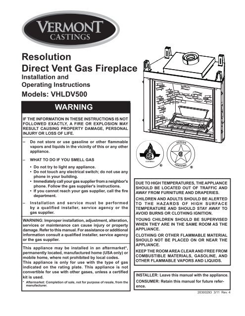
<strong>Resolution</strong><br />
<strong>Direct</strong> <strong>Vent</strong> <strong>Gas</strong> <strong>Fireplace</strong><br />
Installation and<br />
Operating Instructions<br />
Models: VHLDV500<br />
waRnInG<br />
IF tHe InFORMatIOn In tHese InstRuctIOns Is nOt<br />
FOLLOweD exactLy, a FIRe OR expLOsIOn May<br />
ResuLt causInG pROpeRty DaMaGe, peRsOnaL<br />
InjuRy OR LOss OF LIFe.<br />
– Do not store or use gasoline or other flammable<br />
vapors and liquids in the vicinity of this or any other<br />
appliance.<br />
– wHat tO DO IF yOu sMeLL <strong>Gas</strong><br />
• Do not try to light any appliance.<br />
• Do not touch any electrical switch; do not use any<br />
phone in your building.<br />
• Immediately call your gas supplier from a neighbor's<br />
phone. Follow the gas supplier's instructions.<br />
• If you cannot reach your gas supplier, call the fire<br />
department.<br />
– Installation and service must be performed<br />
by a qualified installer, service agency or the<br />
gas supplier.<br />
waRnInG: Improper installation, adjustment, alteration,<br />
services or maintenance can cause injury or property<br />
damage. Refer to this manual. For assistance or additional<br />
information consult a qualified installer, service agency<br />
or the gas supplier.<br />
this appliance may be installed in an aftermarket*,<br />
permanently located, manufactured home (usa only) or<br />
mobile home, where not prohibited by local codes.<br />
this appliance is only for use with the type of gas<br />
indicated on the rating plate. this appliance is not<br />
convertible for use with other gases, unless a certified<br />
kit is used.<br />
* aftermarket: completion of sale, not for purpose of resale, from the<br />
manufacturer.<br />
0293<br />
Due tO HIGH teMpeRatuRes, tHe appLIance<br />
sHOuLD Be LOcateD<br />
VHLDV<br />
Out<br />
cover<br />
OF tRaFFIc anD<br />
away FROM FuRnItuRe anD DRapeRIes.<br />
cHILDRen anD aDuLts sHOuLD Be aLeRteD<br />
tO tHe HaZaRDs OF HIGH suRFace<br />
teMpeRatuRe anD sHOuLD stay away tO<br />
aVOID BuRns OR cLOtHInG IGnItIOn.<br />
yOunG cHILDRen sHOuLD Be supeRVIseD<br />
wHen tHey aRe In tHe saMe ROOM as tHe<br />
appLIance.<br />
cLOtHInG OR OtHeR FLaMMaBLe MateRIaL<br />
sHOuLD nOt Be pLaceD On OR neaR tHe<br />
appLIance.<br />
Keep tHe ROOM aRea cLeaR anD FRee FROM<br />
cOMBustIBLe MateRIaLs, <strong>Gas</strong>OLIne, anD<br />
OtHeR FLaMMaBLe VapORs anD LIquIDs.<br />
InstaLLeR: Leave this manual with the appliance.<br />
cOnsuMeR: Retain this manual for future reference.<br />
20300293 3/11 Rev. 4
<strong>Resolution</strong> <strong>Direct</strong> <strong>Vent</strong> <strong>Gas</strong> <strong>Fireplace</strong> cOntents<br />
thank you and congratulations on your purchase of a<br />
Important safety Information .................................... 3<br />
code approval ............................................................ 4<br />
product Features ........................................................ 5<br />
High Elevations ...................................................... 5<br />
<strong>Gas</strong> Pressures ....................................................... 5<br />
<strong>Gas</strong> Specifications & Orifice Size .......................... 5<br />
<strong>Fireplace</strong> & Framing Dimensions.............................. 6<br />
pre-Installation Information ....................................... 7<br />
Before You Start ..................................................... 7<br />
<strong>Fireplace</strong> Framing .................................................. 7<br />
<strong>Fireplace</strong> Location .................................................. 8<br />
clearances .................................................................. 9<br />
secure <strong>Fireplace</strong> ....................................................... 10<br />
Finishing Material ..................................................... 10<br />
<strong>Vent</strong>ing Installation ....................................................11<br />
Installation Precautions .........................................11<br />
Installation Clearances ..........................................11<br />
Installation Planning ............................................. 12<br />
Vertical Termination .............................................. 12<br />
Horizontal Termination ......................................... 12<br />
How to Use a <strong>Vent</strong> Graph .................................... 14<br />
Vertical Sidewall Installation ................................. 15<br />
Vertical/Horizontal Termination Configurations .... 16<br />
Below Grade Installation ...................................... 17<br />
Vertical Through-the-Roof Applications ................ 18<br />
Installation for Vertical Termination ...................... 19<br />
<strong>Fireplace</strong> Installation ................................................ 21<br />
Check <strong>Gas</strong> Type................................................... 21<br />
Install <strong>Gas</strong> Piping ................................................ 21<br />
check <strong>Gas</strong> pressure ................................................ 23<br />
electrical Installation ............................................... 23<br />
Electrical Wiring ................................................... 23<br />
Junction Box Wiring ............................................. 24<br />
Vermont castings <strong>Fireplace</strong>.<br />
pLease ReaD tHe InstaLLatIOn anD OpeRatIOn InstRuctIOns BeFORe usInG tHe appLIance!<br />
IMpORtant: Read all instructions and warnings carefully before starting installation.<br />
Failure to follow these instructions may result in a possible fire hazard and will void the warranty.<br />
Command Center Wall Installation ....................... 24<br />
Wall Switch Installation ........................................ 24<br />
Signature Command Wiring Diagram .................. 25<br />
Fan/Blower system .................................................. 26<br />
Glass Frame Removal .............................................. 27<br />
stone, Light Bulb and Lens placement .................. 28<br />
Rock wool placement .............................................. 28<br />
Log placement .......................................................... 29<br />
Operating Instructions ............................................ 33<br />
Operating Instructions .......................................... 34<br />
To Turn Off <strong>Gas</strong> .................................................... 34<br />
signature command system<br />
Operation Instructions .......................................... 35<br />
Touch Screen Remote Transmitter Operation ...... 38<br />
cleaning and Maintenance ...................................... 44<br />
Burner, Pilot and Control Compartment ............... 44<br />
Pilot Flame ........................................................... 44<br />
Burner Flame ....................................................... 44<br />
<strong>Vent</strong>ing System .................................................... 45<br />
Glass Door ........................................................... 45<br />
Logs ..................................................................... 45<br />
Rock Wool ........................................................... 45<br />
troubleshooting ....................................................... 46<br />
Replacement parts ................................................... 47<br />
Firebox Components ............................................ 47<br />
Signature Command System ............................... 48<br />
Logs ..................................................................... 50<br />
<strong>Vent</strong>ing Components ............................................ 51<br />
Massachusetts Residents Only............................... 54<br />
warranty ...................................................................... 5<br />
efficiencies................................................................ 56<br />
2 20300293
IMpORtant saFety InFORMatIOn<br />
InstaLLeR<br />
Please leave these instructions with the appliance.<br />
waRnInG<br />
OwneR<br />
<strong>Resolution</strong> <strong>Direct</strong> <strong>Vent</strong> <strong>Gas</strong> <strong>Fireplace</strong><br />
Please retain these instructions for future reference.<br />
• Read this owner’s manual carefully and completely before trying to assemble, operate,<br />
or service this fireplace.<br />
• any change to this fireplace or its controls can be dangerous.<br />
• Improper installation or use of this fireplace can cause serious injury or death from<br />
fire, burns, explosions, electrical shock and carbon monoxide poisoning.<br />
This fireplace is a vented product. This fireplace must be<br />
properly installed by a qualified service person. The glass<br />
door must be properly seated and sealed. If this unit is not<br />
properly installed by a qualified service person with glass<br />
door properly seated and sealed, combustion leakage can<br />
occur.<br />
caRBOn MOnOxIDe pOIsOnInG: Early signs of carbon<br />
monoxide poisoning are similar to the flu with headaches,<br />
dizziness and/or nausea. If you have these signs, the fireplace<br />
may not have been installed properly. Get fresh air<br />
at once! Have the fireplace inspected and serviced by a<br />
qualified service person. Some people are more affected<br />
by carbon monoxide than others. These include pregnant<br />
women, people with heart or lung disease or anemia,<br />
those under the influence of alcohol, and those at high<br />
altitudes.<br />
Propane/LP gas and natural gas are both odorless. An<br />
odor-making agent is added to each of these gases. The<br />
odor helps you detect a gas leak. However, the odor added<br />
to these gases can fade. <strong>Gas</strong> may be present even though<br />
no odor exists.<br />
Make certain you read and understand all warnings. Keep<br />
this manual for reference. It is your guide to safe and proper<br />
operation of this fireplace.<br />
1. This appliance is only for use with the type of gas<br />
indicated on the rating plate. This appliance is not<br />
convertible for use with other gases unless a certified<br />
kit is used.<br />
2. For propane/LP fireplace, do not place propane/LP<br />
supply tank(s) inside any structure. Locate propane/LP<br />
supply tank(s) outdoors. To prevent performance problems,<br />
do not use propane/LP fuel tank of less than 100<br />
lbs. capacity.<br />
3. If you smell gas<br />
• shut off gas supply.<br />
• do not try to light any appliance.<br />
• do not touch any electrical switch; do not use any<br />
phone in your building .<br />
• immediately call your gas supplier from a neighbor’s<br />
phone. Follow the gas supplier’s instructions.<br />
4. Never install the fireplace<br />
• in a recreational vehicle<br />
• where curtains, furniture, clothing, or other flammable<br />
objects are less than 42" from the front, top,<br />
or sides of the fireplace<br />
• in high traffic areas<br />
• in windy or drafty areas<br />
5. This fireplace reaches high temperatures. Keep children<br />
and adults away from hot surfaces to avoid burns or<br />
clothing ignition. <strong>Fireplace</strong> will remain hot for a time after<br />
shutdown. Allow surfaces to cool before touching.<br />
6. Young children should be carefully supervised when<br />
they are in the same room as the appliance. Toddlers,<br />
young children and others may be susceptible to accidental<br />
contact burns. A physical barrier is recommended<br />
if there are at risk individuals in the house. To restrict<br />
access to a fireplace or stove, install an adjustable<br />
safety gate to keep toddlers, young children and other<br />
at risk individuals out of the room and away from hot<br />
surfaces.<br />
7. Do not modify fireplace under any circumstances. Any<br />
parts removed for servicing must be replaced prior to<br />
operating fireplace.<br />
8. Turn fireplace off and let cool before servicing, installing,<br />
or repairing. Only a qualified service person should<br />
install, service, or repair the fireplace. Have burner<br />
system inspected annually by a qualified service<br />
person.<br />
9. You must keep control compartments, burners, and<br />
circulating air passages clean. More frequent cleaning<br />
may be needed due to excessive lint and dust. Turn off<br />
the gas valve and pilot light before cleaning fireplace.<br />
10. Have venting system inspected annually by a qualified<br />
service person. If needed, have venting system cleaned<br />
or repaired. Refer to Cleaning and Maintenance, Page<br />
44.<br />
11. Keep the area around your fireplace clear of combustible<br />
materials, gasoline, and other flammable vapor and<br />
liquids. Do not run fireplace where these are used or<br />
stored. Do not place items such as clothing or decorations<br />
on or around fireplace.<br />
20300293 3
<strong>Resolution</strong> <strong>Direct</strong> <strong>Vent</strong> <strong>Gas</strong> <strong>Fireplace</strong> IMpORtant saFety InFORMatIOn and cODe appROVaL<br />
Continued from page 3<br />
12. Do not use this fireplace to cook food or burn paper or<br />
other objects.<br />
13. Never place anything on top of fireplace.<br />
14. Do not use any solid fuels (wood, coal, paper, cardboard,<br />
etc.) in this fireplace. Use only the gas type<br />
indicated on rating plate.<br />
15. This appliance, when installed, must be electrically<br />
grounded in accordance with local codes or in the<br />
absence of local codes, with the National Electrical<br />
Code, ANSI/NFPA 70, or the Canadian Electrical Code,<br />
CSA C22.1.<br />
16. Do not obstruct the flow of combustion and ventilation<br />
air in any way. Provide adequate clearances around<br />
air openings into the combustion chamber along with<br />
adequate accessibility clearance for servicing and<br />
proper operation.<br />
17. When the appliance is installed directly on carpeting,<br />
tile or other combustible material other than wood flooring,<br />
you must set appliance on a metal or wood panel<br />
or hearth pad extending the full width and depth of the<br />
appliance.<br />
18. Do not use fireplace if any part has been exposed to<br />
or has been under water. Immediately call a qualified<br />
service technician to inspect the appliance and replace<br />
any part of the control system and any gas control which<br />
as been submerged in water.<br />
19. Do not operate fireplace if any log is broken.<br />
20. Do not use a blower insert, heat exchanger insert, or<br />
any other accessory not approved for use with this<br />
fireplace.<br />
21. Do not operate the fireplace with glass door removed,<br />
cracked, or broken.<br />
cODe appROVaL<br />
<strong>Direct</strong> <strong>Vent</strong> type appliances draw all combustion air from<br />
outside of the dwelling through the vent pipe.<br />
These appliances have been tested by CSA and found to<br />
comply with the established standards for DIRECT VENT<br />
GAS FIREPLACE HEATERS in the USA and Canada as<br />
follows:<br />
LIsteD <strong>Vent</strong>eD <strong>Gas</strong> FIRepLace HeateR<br />
TESTED TO:<br />
ANSI Z21.88-2009 / CSA 2.33-2009 STANDARDS<br />
A manufactured home (USA only) or mobile home OEM<br />
installation must conform with the Manufactured Home<br />
Construction and Safety Standard, title 24 cFR, part<br />
3280, or when such a standard is not applicable, the<br />
standard for Manufactured Home Installations, ansI/<br />
ncsBcs a225.1, or standard for <strong>Gas</strong> equipped Recreational<br />
Vehicles and Mobile Housing, csa Z240.4.<br />
IMpORtant:<br />
pLease ReaD tHe FOLLOwInG<br />
caReFuLLy<br />
It is normal for fireplaces fabricated of steel to give off<br />
some expansion and/or contraction noises during the<br />
start up or cool down cycle. Similar noises are found with<br />
your furnace heat exchanger or car engine.<br />
IMpORtant:<br />
pLease ReaD tHe FOLLOwInG<br />
caReFuLLy<br />
It is not unusual for gas fireplaces to give off some odor<br />
the first time it is burned. This is due to the manufacturing<br />
process.<br />
please ensure that your room is well ventilated<br />
during burn off — open all windows.<br />
It is recommended that you burn your fireplace for at<br />
least ten (10) hours the first time you use it. Place the<br />
fan switch in the “OFF” position during this time.<br />
WARNING<br />
4 20300293<br />
waRnInG<br />
never connect unit to private (nonutility)<br />
gas wells. this gas is commonly<br />
known as wellhead gas.<br />
!<br />
!<br />
HOT GLASS WILL<br />
CAUSE BURNS.<br />
DO NOT TOUCH GLASS<br />
UNTIL COOLED.<br />
NEVER ALLOW CHILDREN<br />
TO TOUCH GLASS.<br />
AVERTISSEMENT<br />
Un panneau vitré chaud peut<br />
causer des brûlures.<br />
Laissez refroidir le panneau<br />
vitré avant d’y toucher.<br />
Ne laisser jamais les enfants<br />
toucher le panneau vitré.
pRODuct FeatuRes<br />
• This appliance has been certified for use with either<br />
natural or propane gas. See appropriate data plates.<br />
• This appliance is not for use with solid fuels.<br />
• The appliance is approved for bedroom or bedsitting<br />
room installations.<br />
• The appliance must be installed in accordance with local<br />
codes if any. If none exist use the current installation<br />
code. ANSI Z223.1/NFPA 54 in the USA, CSA B149 in<br />
Canada.<br />
• This appliance is mobile home approved.<br />
• The appliance must be properly connected to a venting<br />
system.<br />
• The appliance is not approved for closet or recessed<br />
installations.<br />
HIGH eLeVatIOns<br />
Input ratings are shown in BTU per hour and are certified<br />
without deration for elevations up to 4,500 feet (1,370<br />
m) above sea level.<br />
For elevations above 4,500 feet (1,370 m) in USA,<br />
installations must be in accordance with the current<br />
ANSI Z223.1/NFPA 54 and/or local codes having jurisdiction.<br />
In Canada, please consult provincial and/or local authorities<br />
having jurisdiction for installations at elevations<br />
above 4,500 feet (1,370 m).<br />
<strong>Gas</strong> pRessuRes<br />
Natural Propane (LP)<br />
Inlet Minimum 4.5” w.c. 11.0” w.c.<br />
Inlet Maximum 10.5” w.c. 13.0” w.c.<br />
Manifold Pressure 3.5” w.c. 10.0” w.c.<br />
<strong>Resolution</strong> <strong>Direct</strong> <strong>Vent</strong> <strong>Gas</strong> <strong>Fireplace</strong><br />
Access Panel<br />
Control Box<br />
<strong>Gas</strong> Valve<br />
Command Center<br />
Figure 1 -<br />
VHLDV <strong>Fireplace</strong> Controls<br />
FP2594<br />
<strong>Gas</strong> VHLDV specIFIcatIOns controls & ORIFIce sIZe<br />
20300293 5<br />
FP2594<br />
Btu/hr Input<br />
Max. Min. Min. Front<br />
Model Fuel all all Burners<br />
Burners Burners Only<br />
VHLDV500NTSC Nat. 50,000 35,500 17,500<br />
VHLDV500PTSC LP 50,000 38,500 17,500<br />
Orifice size<br />
Model Fuel Front Rear<br />
VHLDV500 Nat. 2.3 mm #30 (.1285)<br />
VHLDV500 LP #50 (.070") #55 (.052")
<strong>Resolution</strong> <strong>Direct</strong> <strong>Vent</strong> <strong>Gas</strong> <strong>Fireplace</strong> FIRepLace and FRaMInG DIMensIOns<br />
56” (1434 mm)<br />
39”<br />
1014 mm)<br />
56” (1434 mm)<br />
79” (2029 mm)<br />
Figure 2 -<br />
<strong>Fireplace</strong> and Framing Dimensions<br />
Min. Rough<br />
Opening<br />
Height<br />
Min. Rough<br />
Opening<br />
Depth<br />
23”<br />
(606 mm)<br />
23”<br />
(606 mm)<br />
4”<br />
(108 mm)<br />
44”<br />
(1137 mm)<br />
44”<br />
(1127 mm)<br />
38”<br />
(967 mm)<br />
30”<br />
(816 mm)<br />
4”<br />
(102 mm)<br />
730129<br />
DVKHL/KHLDV dims<br />
32” (816 mm)<br />
24”<br />
(622 mm)<br />
49” (1253 mm)<br />
Min. Rough Opening Width<br />
36” (914 mm)<br />
39” (1003 mm)<br />
48” (1243 mm)<br />
8” (218 mm)<br />
1”<br />
(25 mm)<br />
1/2” or 5/8”<br />
38”<br />
(976 mm)<br />
6 20300293
pRe-InstaLLatIOn InFORMatIOn<br />
BeFORe yOu staRt<br />
Read this homeowner manual thoroughly and follow all<br />
instructions carefully. Inspect all contents for shipping<br />
damage and immediately inform your dealer if any damage<br />
is found. Do not install any unit with damaged, incomplete,<br />
or substitute parts. Check your packing list to verify that<br />
all listed parts have been received. You should have the<br />
following:<br />
• <strong>Fireplace</strong> (Firebox and Burner System)<br />
• Log Set<br />
• Rock Wool<br />
• Noncombustible Panel<br />
IteMs RequIReD FOR InstaLLatIOn<br />
• Phillips Screwdriver • Framing Materials<br />
• Hammer • Wall Finishing Materials<br />
• Saw and/or saber saw • Level<br />
• Measuring Tape • Pliers<br />
• Electric Drill and Bits • Square<br />
• Pipe Wrench • Tee Joint<br />
• Noncombustible finishing material or dura-rock*<br />
• Caulking Material (noncombustible)<br />
• <strong>Fireplace</strong> Surround Material (noncombustible)<br />
• Piping Complying with Local Codes<br />
• Pipe Sealant Approved for use with Propane/LPG<br />
(Resistant to sulfur compounds)<br />
* Only used if desired to cover painted face other than using tiles<br />
or marble. If tiles or marble are used around the face then the<br />
non-combustible material is not needed.<br />
waRnInG<br />
nOte<br />
Do not fill spaces around firebox with<br />
insulation or other materials. this could<br />
cause a fire.<br />
cOLD cLIMate InsuLatIOn<br />
If you live in a cold climate, seal all cracks<br />
around your appliance, and wherever cold air<br />
could enter the room, with noncombustible<br />
material. It is especially important to insulate<br />
the outside chase cavity between the studs<br />
and under the floor on which the appliance<br />
rests, if the floor is above ground level.<br />
FIReBOx FRaMInG<br />
<strong>Resolution</strong> <strong>Direct</strong> <strong>Vent</strong> <strong>Gas</strong> <strong>Fireplace</strong><br />
Firebox framing can be built before or after the appliance<br />
is set in place. Refer to Figure 2 for firebox dimensions<br />
and framing. Construct firebox framing following Figure<br />
2 for your specific installation requirements. The framing<br />
headers may rest on the top of the firebox standoffs. Do<br />
not bring headers below top of standoffs. nOte: When<br />
planning your framing and installation, keep in mind that<br />
your gas line will come in on the right side of the box (as<br />
you are facing it) and your electricity will come in on the<br />
left side.<br />
The firebox may be installed directly on a combustible floor<br />
or raised on a platform of an appropriate height. When<br />
the firebox is installed directly on carpeting, tile, or other<br />
combustible material, other than wood flooring, the firebox<br />
shall be installed on a metal or wood panel extending the<br />
full width and depth of the enclosure.<br />
20300293 7<br />
waRnInG<br />
unit framing is to be rectangular front to<br />
back. Failure to do so will cause fire and<br />
damage to property.
<strong>Resolution</strong> <strong>Direct</strong> <strong>Vent</strong> <strong>Gas</strong> <strong>Fireplace</strong> pRe-InstaLLatIOn InFORMatIOn<br />
FIRepLace LOcatIOn<br />
Plan for the installation of your appliance. This includes determining where the unit is to be installed,<br />
the vent configuration to be used, framing and finishing details, and whether any optional accessories<br />
(i.e. blower, wall switch, or remote control) are desired. Consult your local building code agency to<br />
ensure compliance with local codes, including permits and inspections.<br />
The following factors should be taken into consideration:<br />
• Clearance to side-wall, ceiling, woodwork, and windows. Minimum clearances to combustibles<br />
must be maintained.<br />
• This fireplace may be installed along a wall, across a corner, or use an exterior chase. Refer to<br />
Figure 3 for suggested locations.<br />
• Location should be out of high traffic areas and away from furniture and draperies due to heat<br />
from appliance.<br />
• Never obstruct the front opening of the fireplace.<br />
• Do not install in the vicinity where gasoline or other flammable liquids may be stored.<br />
• <strong>Vent</strong> pipe routing. Refer to the <strong>Vent</strong>ing section found in this manual for allowable venting configurations.<br />
• These units can be installed in a bedroom. See National Fuel <strong>Gas</strong> Code ANSI Z233.1/NFPA 54<br />
— (current edition), the Uniform Mechanical Code — (current edition), and Local Building Codes<br />
for specific installation requirements.<br />
• These units can be installed in a bathroom.<br />
Y<br />
Y<br />
E A<br />
D<br />
F<br />
Figure 3 -<br />
Locating <strong>Gas</strong> <strong>Fireplace</strong><br />
C<br />
X<br />
B<br />
FP1948<br />
A Flat on Wall<br />
B Cross Corner<br />
C Island**<br />
D Room Divider*<br />
E Flat on Wall Corner*<br />
F Chase Installation<br />
Y 6" Minimum<br />
** Island (C) and room divider (D) installation is possible as long<br />
as the horizontal portion of vent system (X) does not exceed<br />
20'. Refer to Installing Horizontal Termination Configuration<br />
on Page 15.<br />
* When you install your fireplace in (D) room divider or (E)<br />
flat on wall corner positions (Y), a minimum of 6" clearance<br />
must be maintained from perpendicular wall and front of<br />
fireplace.<br />
8 20300293
cLeaRances<br />
cLeaRances tO cOMBustIBLes<br />
waRnInG<br />
72” Minimum<br />
Ceiling<br />
FP2128<br />
Follow these instructions carefully to ensure safe installation. Failure to<br />
follow instructions exactly can create a fire hazard.<br />
the appliance cannot be installed on a carpet, tile or other combustible<br />
material other than wood flooring. If installed on carpet or vinyl flooring,<br />
the appliance shall be installed on a metal, wood or noncombustible<br />
material panel extending full width and depth of the appliance.<br />
12” Max.<br />
Depth<br />
6” Min.<br />
Hearth Minimum<br />
<strong>Fireplace</strong> Opening<br />
FP2595<br />
mantel clearances<br />
2 1 /2” Max Depth<br />
16” Min.<br />
From Opening<br />
10” min.<br />
From Opening<br />
Hearth<br />
8” Min.<br />
Noncombustible<br />
Figure 4 -<br />
Clearances from the mantel, ceiling, and side wall.<br />
16"<br />
(406 mm)<br />
<strong>Resolution</strong> <strong>Direct</strong> <strong>Vent</strong> <strong>Gas</strong> <strong>Fireplace</strong><br />
12" (305 mm)<br />
6" (152 mm)<br />
2 1 /2" (64 mm)<br />
12"<br />
(305 mm)<br />
10"<br />
(254 mm)<br />
FP2204<br />
mantel clearances<br />
ManteL cLeaRances<br />
FP2129<br />
nOte: the combustible area above the facing must not protrude more than mantel 3/4" leg from the facing. If it<br />
does, it is considered a mantel and must meet the mantel requirements listed in this manual.<br />
20300293 9<br />
FP2129<br />
Wall<br />
Top of <strong>Fireplace</strong><br />
Opening<br />
<strong>Fireplace</strong> Opening<br />
top View<br />
side View<br />
2<br />
3"<br />
5"<br />
6"<br />
1 1"<br />
3<br />
/2"<br />
1 1<br />
/2"<br />
1 /2"<br />
Figure 5 -<br />
Mantel clearances<br />
Stud<br />
Insulation<br />
Board<br />
Standoff<br />
FP2235<br />
4 1 /2"<br />
45°
<strong>Resolution</strong> <strong>Direct</strong> <strong>Vent</strong> <strong>Gas</strong> <strong>Fireplace</strong><br />
The fireplace must be secured to the floor and/or to framing studs as shown in Figure 6. Use two<br />
(2) wood screws or masonry/ concrete screws to secure fireplace to the floor. Use four (4) screws<br />
to attach fireplace to framing. The side nailing flanges are 1/2" or 5/8" to accommodate different<br />
wall thickness.<br />
nOte<br />
Figure 6 -<br />
Secure <strong>Fireplace</strong> to Floor<br />
and Framing Studs<br />
never install combustible materials<br />
over front face of fireplace.<br />
FInIsHInG MateRIaL<br />
Noncombustible Material<br />
6”<br />
Secure to Floor Behind<br />
Access Panels<br />
secuRe FIRepLace to FLOOR or FRaMInG<br />
Noncombustible<br />
Material Must Rise<br />
at Least to Top of<br />
Stand off<br />
Nailing Flange<br />
FP2130<br />
secure fireplace to floor<br />
Framing Members<br />
All Combustible Materials<br />
Must Keep 3/4" Spacing<br />
nOte: Any remote wiring (i.e. remote control, wall switch, and optional fan) must be done prior to<br />
final finishing to avoid costly reconstruction.<br />
Only noncombustible materials (i.e. brick, tile, slate, steel, or other materials with a UL fire rating of<br />
Zero) may be used to cover the black painted face of the appliance. It is permissible to bring combustible<br />
wall board to the top of the stand-offs on the top and the sides of the unit. A 300°F minimum<br />
adhesive may be used to attach facing materials to the black surface. If joints between the finished<br />
wall and the fireplace surround are sealed, a 300°F minimum sealant material (General Electric<br />
RTV103 or equivalent) must be used.<br />
10 20300293<br />
FP2130
<strong>Vent</strong>InG InstaLLatIOn<br />
waRnInG<br />
Read all instructions completely and thoroughly before attempting<br />
installation. Failure to do so could result in serious injury, property<br />
damage or loss of life. Operation of improperly installed and maintained<br />
venting system could result in serious injury, property damage or loss<br />
of life.<br />
InstaLLatIOn pRecautIOns<br />
Consult local building codes before beginning the<br />
installation. The installer must make sure to select the<br />
proper vent system for installation. Before installing vent<br />
kit, the installer must read this fireplace manual and vent<br />
kit instructions.<br />
Only a qualified installer/service person should install venting<br />
system. The installer must follow these safety rules:<br />
• Wear gloves and safety glasses for protection.<br />
• Use extreme caution when using ladders or when<br />
on rooftops.<br />
• Be aware of electrical wiring locations in walls and<br />
ceilings.<br />
The following actions will void the warranty on your venting<br />
system:<br />
nOtIce<br />
waRnInG<br />
waRnInG<br />
• Installation of any damaged venting component.<br />
• Unauthorized modification of the venting system.<br />
• Installation of any component part not manufactured<br />
or approved by MHSC.<br />
• Installation other than permitted by these instructions.<br />
Failure to follow these instructions will void<br />
the warranty.<br />
this fireplace must be vented to the outside. the venting system must<br />
neVeR be attached to a chimney serving a separate solid fuel burning<br />
appliance. each gas appliance must use a separate vent system. Do not<br />
use common vent systems.<br />
<strong>Resolution</strong> <strong>Direct</strong> <strong>Vent</strong> <strong>Gas</strong> <strong>Fireplace</strong><br />
* A minimum of 3" clearance<br />
to the top is required along<br />
horizontal length until flue pipe<br />
penetrates outside wall.<br />
** A minimum FP25961"<br />
clearance<br />
to combustibles venting permitted clearanceall<br />
around flue at outside wall<br />
20300293 11<br />
*3”<br />
24" Vertical Rise<br />
Required Before<br />
Horizontal Run<br />
FP2596<br />
Figure 7 -<br />
Combustible Clearances for <strong>Vent</strong> Pipe<br />
**1”<br />
**1”<br />
73”<br />
(1854 mm)<br />
Horizontal sections of this vent system require a minimum of 3" clearances to combustibles at<br />
the top of the flue and 1" clearance at the sides and bottom until the flue penetrates the outside<br />
wall. a minimum 1" clearance all around the flue is acceptable at this point of penetration. unless<br />
the vertical run is 7Z\x' or higher from floor of fireplace, the clearance for horizontal run is 1" on<br />
all sides.<br />
Vertical sections of this vent system require a minimum of 2" clearance to combustibles at the<br />
top of the unit directly above the stand-off. a minimum of 1" clearance all around the flue is<br />
acceptable thereafter.
<strong>Resolution</strong> <strong>Direct</strong> <strong>Vent</strong> <strong>Gas</strong> <strong>Fireplace</strong> <strong>Vent</strong>InG InstaLLatIOn<br />
InstaLLatIOn pLannInG<br />
There are two basic types of direct-vent installation:<br />
nOtIce<br />
waRnInG<br />
• Horizontal Termination<br />
• Vertical Termination<br />
It is important to select the proper length of vent pipe for<br />
the type of termination you choose. It is also important to<br />
note the wall thickness.<br />
FOR HORIZOntaL teRMInatIOn<br />
Select the amount of vertical rise desired. All horizontal run<br />
of venting must have 1/4" rise for every 12" of run towards<br />
the termination below 7Z\x" of vertical rise from floor of fireplace.<br />
With 7Z\x feet or more of vertical rise from the floor<br />
of the fireplace, the horizontal run may be level. NEVER<br />
run vent piping down.<br />
You may use up to three 90° elbows in this vent configuration.<br />
Refer to Vertical/Horizontal Termination Configurations<br />
on Page 16.<br />
Horizontal venting which incorporates the twist lock pipe<br />
must be installed on a level plane without an inclining or<br />
declining slope.<br />
FOR VeRtIcaL teRMInatIOn<br />
Measure the distance from the fireplace floor to the ceiling.<br />
Add the ceiling thickness, the vertical rise in an attic<br />
or second story, and allow for sufficient vent height above<br />
the roof line.<br />
nOte: You may use two 45° elbows in place of a 90° elbow.<br />
You must follow rise to run ratios when using 45° elbows.<br />
The appliance is approved for use with three 90° elbows<br />
maximum or a combination of 90° and 45° elbows up to<br />
a maximum of 270°.<br />
nOtIce<br />
12 20300293<br />
waRnInG<br />
never run the vent pipe down. this may<br />
cause excessive temperatures which could<br />
cause a fire.<br />
For two-story applications, firestops are required at each<br />
floor level. If an offset is needed in the attic, additional pipe<br />
and elbows will be required.<br />
You may use a chase with a vent termination with exposed<br />
pipe on the exterior of the house. See Installing A <strong>Vent</strong><br />
System in an Outside Chase below. If pipe is enclosed in<br />
chase, it is not exposed.<br />
It is very important that the venting system maintain its balance<br />
between the combustion air intake and the flue gas<br />
exhaust. Certain limitations apply to vent configurations<br />
and must be strictly followed.<br />
InstaLLInG a <strong>Vent</strong> systeM In an<br />
OutsIDe cHase<br />
A chase is a vertical boxlike structure built to enclose<br />
venting that runs along the outside of a building. A chase<br />
is required for such venting.<br />
treatment of firestops and construction of the chase may vary from building<br />
type to building type. these instructions are not substitutes for the requirements<br />
of local building codes. you must follow all local building codes.<br />
when installing in a chase, you should insulate the chase as you would the<br />
outside walls of your home. this is especially important in cold climates.<br />
Insulation should be considered a combustible material. Maintain proper<br />
clearances to all combustible materials.<br />
always maintain minimum clearances around vent systems. the minimum clearances to<br />
combustibles for horizontal vent pipe are 3" at the top* and 1" at the sides and bottom of the vent<br />
system until the pipe penetrates the nearest vertical wall (1" required). a 1" minimum clearance<br />
all around the pipe must be maintained at outside wall and on vertical runs. Do not pack the<br />
open air spaces with insulation or other materials. this could cause high temperatures and may<br />
present a fire hazard.<br />
*unless the vertical run is 7Z\x feet or higher from floor of fireplace, the clearance for the horizontal<br />
run is 1" on all sides.
<strong>Vent</strong>InG InstaLLatIOn<br />
GeneRaL <strong>Vent</strong>InG InFORMatIOn - teRMInatIOn LOcatIOn<br />
Figure 8 -<br />
Termination Locations<br />
L<br />
D<br />
V<br />
E<br />
B<br />
CFM145a<br />
F<br />
C<br />
V Fixed<br />
Closed<br />
V<br />
V<br />
B B<br />
1 In accordance with the current CSA-B149 Installation Codes<br />
2 In accordance with the current ANSI Z223.1/NFPA 54 National Fuel<br />
<strong>Gas</strong> Codes<br />
† A vent shall not terminate directly above a sidewalk or paved<br />
driveway which is located between two single family<br />
dwellings and serves both dwellings<br />
only permitted if veranda, porch, deck or balcony is fully open on a<br />
minimum 2 sides beneath the floor:<br />
Operable<br />
B<br />
A<br />
INSIDE<br />
CORNER DETAIL<br />
V<br />
B<br />
Fixed<br />
Operable<br />
Closed<br />
<strong>Resolution</strong> <strong>Direct</strong> <strong>Vent</strong> <strong>Gas</strong> <strong>Fireplace</strong><br />
20300293 13<br />
G<br />
V<br />
A<br />
J<br />
V VENT TERMINATION X AIR SUPPLY INLET AREA WHERE TERMINAL IS NOT PERMITTED<br />
V<br />
B<br />
X<br />
CFM145a<br />
DV Termin Location<br />
5/01/01 Rev. 12/05/01<br />
sta<br />
H<br />
canadian Installations 1 us Installations 2<br />
A = Clearance above grade, veranda, porch,<br />
deck, or balcony<br />
12” (30 cm) 12” (30 cm)<br />
B = Clearance to window or door that may be 6” (15 cm) for appliances 6” (15 cm) for appliances<br />
opened < 10,000BTU/h (3kW), 12” (30 cm) < 10,000 BTU/h (3kW), 9”<br />
for appliances > 10,000 Btuh (3kW) and (23 cm) for appliances > 10,000<br />
< 100,000 BTU/h (30kW), 36” (91 cm) Btuh (3kW) and < 50,000 BTU/h<br />
for appliances > 100,000 BTU/h (30kW) (15kW), 12” (30 cm) for<br />
appliances > 50,000 BTU/h(15kW)<br />
C = Clearance to permanently closed window 12” (305 mm) recommended to 12” (305 mm) recommended to<br />
D = Vertical clearance to ventilated soffit located<br />
prevent window condensation prevent window condensation<br />
above the terminal within a horizontal<br />
distance of 2’ (610mm) from the center<br />
line of the terminal<br />
18” (458 mm) 18” (458 mm)<br />
E = Clearance to unventilated soffit 12” (305 mm); 12" (305 mm);<br />
Clearance to vinyl soffit (30" (762 mm) Clearance to vinyl soffit (30" (762 mm)<br />
F = Clearance to outside corner see next page see next page<br />
G = Clearance to inside corner (see next page) see next page see next page<br />
H = Clearance to each inside of center line 3’ (91 cm) within a height of 15’ (5 m) 3’ (91 cm) within a height of 15’<br />
extended above meter/regulator assembly above the meter/regulator assembly (5 m) above the meter/regulator assy<br />
I = Clearance to service regulator vent outlet 3’ (91 cm) 3’ (91 cm)<br />
J = Clearance to nonmechanical air supply inlet 6” (15 cm) for appliances < 10,000 6” (15 cm) for appliances<br />
to building or the combustion air inlet to any BTU/h (3kW), 12” (30 cm) for < 10,000 BTU/h (3kW), 9”<br />
other appliances appliances > 10,000 BTU/h (3kW) and (23 cm) for appliances > 10,000<br />
< 100,000 Btuh (30kW), 36” (91 cm) BTU/h (3kW) and < 50,000 BTU/h<br />
for appliances > 100,000 BTU/h (30kW) (15kW), 12” (30 cm) for<br />
appliances > 50,000 BTU/h(15kW)<br />
K = Clearance to a mechanical air supply inlet 6’ (1.83 m) 3’ (91 cm) above if within 10'<br />
(3 m) horizontally<br />
L = Clearance above paved sidewalk or paved<br />
driveway located on public property<br />
7’ (2.13 m)† 7’ (2.13 m)†<br />
M = Clearance under veranda, porch, deck or<br />
balcony<br />
12” (30 cm) 12” (30cm)<br />
I<br />
M<br />
NOTE: 1. Local codes or regulations may require different<br />
clearances.<br />
2. The special venting system used on <strong>Direct</strong> <strong>Vent</strong> <strong>Fireplace</strong>s<br />
are certified as part of the appliance, with clearances<br />
tested and approved by the listing agency.<br />
3. MHSC assumes no responsibility for the improper<br />
performance of the appliance when the venting system<br />
does not meet these requirements.<br />
V<br />
K<br />
X
<strong>Resolution</strong> <strong>Direct</strong> <strong>Vent</strong> <strong>Gas</strong> <strong>Fireplace</strong><br />
Figure 9 -<br />
Termination<br />
Clearances<br />
HOw tO use tHe <strong>Vent</strong> GRapH<br />
The <strong>Vent</strong> Graph should be read in conjunction with the<br />
following vent installation instructions to determine the<br />
relationship between the vertical and horizontal dimensions<br />
of the vent system.<br />
1. Determine the height of the center of the horizontal vent<br />
pipe exiting through the outer wall. Using this dimension<br />
on the Sidewall <strong>Vent</strong> Graph below, locate the point<br />
intersecting with the slanted graph line.<br />
2. From the point of this intersection, draw a vertical line<br />
to the bottom of the graph.<br />
3. Select the indicated dimension, and position the fireplace<br />
in accordance with same.<br />
Example: If the vertical dimension from the floor of the<br />
fireplace is 11' (3.4 m) the horizontal run to the face of<br />
the outer wall must not exceed 16' (4.9 m).<br />
Sidewall <strong>Vent</strong> Graph showing the relationship between<br />
vertical and horizontal dimensions for a <strong>Direct</strong> <strong>Vent</strong> flue<br />
system.<br />
Termination Clearances<br />
Termination clearances for buildings with combustible and noncombustible exteriors.<br />
Inside Corner<br />
Outside Corner<br />
Alcove Applications*<br />
G<br />
V<br />
Balcony -<br />
with no side wall<br />
G =<br />
Combustible<br />
6" (152 mm)<br />
Noncombustible<br />
2" (51 mm)<br />
M<br />
V<br />
M =<br />
Combustible &<br />
Noncombustible<br />
12" (305 mm)<br />
V<br />
Balcony -<br />
with perpendicular side wall<br />
M<br />
F<br />
Combustible &<br />
Noncombustible<br />
M = 24" (610 mm)<br />
P = 20” (508 mm)<br />
V<br />
F =<br />
Combustible<br />
6" (152 mm)<br />
Noncombustible<br />
2" (51 mm)<br />
72" From Floor<br />
to Center<br />
14 20300293<br />
P<br />
40<br />
38<br />
36<br />
34<br />
32<br />
30<br />
28<br />
26<br />
24<br />
22<br />
20<br />
18<br />
16<br />
14<br />
12<br />
10<br />
8<br />
6<br />
4<br />
2<br />
<strong>Vent</strong>InG InstaLLatIOn<br />
Dimensions in<br />
Feet<br />
eg: A<br />
2 4 6 8 10 12 14 16 18 20<br />
Figure 10 - Horizontal dimension from the finished outside wall<br />
Rear Wall <strong>Vent</strong>ing to the center of the pipe on the fireplace<br />
Graph (No Horizontal<br />
Elbows)<br />
C<br />
O<br />
D<br />
V<br />
E<br />
C<br />
E = Min. 6” (152 mm) for<br />
non-vinyl sidewalls<br />
Min. 12” (305 mm) for<br />
vinyl sidewalls<br />
O = 8’ (2.4 m) Min.<br />
No.<br />
of Caps DMin. CMax.<br />
1 3’ (914 mm) 2 x DActual<br />
2 6’ (1.8 m) 1 x DActual<br />
3 9’ (2.7 m) 2/3 x DActual<br />
4 12’ (3.7 m) 1/2 x DActual<br />
DMin. = # of Termination caps x 3<br />
CMax. = (2 / # termination caps) x DActual<br />
584-15<br />
*nOte: Termination in an alcove space (spaces open only on one side and with an overhang) is permitted with the dimensions specified for vinyl or<br />
non-vinyl siding and soffits. 1. There must be a 3’ (914 mm) minimum between termination caps. 2. All mechanical air intakes within 10’ (1 m) of a<br />
termination cap must be a minimum of 3’ (914 mm) below the termination cap. 3. All gravity air intakes within 3’ (914 mm) of a termination cap must<br />
be a minimum of 1’ (305 mm) below the termination cap.<br />
FP2132<br />
sidewall vent graph<br />
Vertical Dimension From the Floor of Unit to the Center of the<br />
Horizontal <strong>Vent</strong> Pipe
<strong>Vent</strong>InG InstaLLatIOn<br />
VeRtIcaL sIDewaLL InstaLLatIOn<br />
nOte: sealant is not required to assemble fireplace<br />
venting. Do not use silicone sealant at the inner flue<br />
exhaust connections.<br />
step 1<br />
Locate vent opening on the wall. It may be necessary to<br />
first position the fireplace and measure to obtain hole location.<br />
Depending on whether the wall is combustible or<br />
noncombustible, cut opening to size. Figure 11 (For combustible<br />
walls first frame in opening.)<br />
combustible walls: Cut a 10Z\x”H x 10Z\x”W (267 x 267<br />
mm) hole through the exterior wall and frame as shown.<br />
Figure 11<br />
noncombustible walls: Hole opening must be 8Z\x” (216<br />
mm) in diameter.<br />
10Z\x”<br />
(267 mm)<br />
Min.<br />
<strong>Vent</strong> Opening for combustible walls<br />
10Z\x”<br />
(267 mm) Min.<br />
<strong>Fireplace</strong> Hearth<br />
Framing Detail<br />
Opening for noncombustible wall<br />
8Z\x”<br />
(216 mm)<br />
Figure 11 -<br />
<strong>Fireplace</strong> Hearth<br />
Locate vent opening on wall<br />
FP2293<br />
step 2<br />
Secure firestop to the inside frame, center in the 10Z\x" x<br />
10Z\x" vent opening.<br />
VO584-100<br />
step 3 <strong>Vent</strong> Opening<br />
Place fireplace into 2/99 position. djtMeasure<br />
the vertical height<br />
(X) required from the base of the flue collars to the center<br />
of the wall opening. Figure 12<br />
step 4<br />
Using appropriate length of pipe section(s) attach to fireplace<br />
with three (3) screws. Follow with the installation of<br />
the elbow.<br />
step 5<br />
Measure the horizontal length requirement figuring a 1Z\v”<br />
(32 mm) overlap, i.e. from the elbow to the outside wall<br />
cap. Figure 13<br />
Figure 12 -<br />
Vertical Height<br />
Requirement<br />
Figure 13 -<br />
Horizontal Length<br />
Requirement<br />
<strong>Resolution</strong> <strong>Direct</strong> <strong>Vent</strong> <strong>Gas</strong> <strong>Fireplace</strong><br />
20300293 15<br />
X<br />
X<br />
FP1181<br />
FP1182<br />
always install horizontal venting on a level<br />
plane.<br />
step 6<br />
Use appropriate length of pipe sections - telescopic or<br />
fixed - and install.<br />
sealing vent pipe and firestop gaps with high temperature<br />
sealant will restrict cold air being drawn in<br />
around fireplace.<br />
step 7<br />
Guide the vent terminations 5” and 8” collard into their<br />
respective vent pipes. Double check that the vent pipes<br />
overlap the collars by a minimum of 1Z\v" (32 mm). Secure<br />
the termination to the wall with screws provided and caulk<br />
around the wall plate to weatherproof. As an alternative to<br />
screwing the termination directly to the wall, you may also<br />
use expanding plugs or an approved exterior construction<br />
adhesive.<br />
support horizontal pipes every 36” (914<br />
mm) with metal pipe straps.<br />
X<br />
X
<strong>Resolution</strong> <strong>Direct</strong> <strong>Vent</strong> <strong>Gas</strong> <strong>Fireplace</strong><br />
VeRtIcaL/HORIZOntaL teRMInatIOn<br />
cOnFIGuRatIOns<br />
since it is very important that the venting system maintain<br />
its balance between the combustion air intake and<br />
the flue gas exhaust, certain limitations as to vent configurations<br />
apply and must be strictly adhered to.<br />
The <strong>Vent</strong> Graph, showing the relationship between vertical<br />
and horizontal side wall venting, will help to determine the<br />
various dimensions allowable. Figure 10<br />
nOte: Horizontal sections of this vent system require<br />
a minimum of 3" clearances to combustibles at the top<br />
of the flue and 1" clearance at the sides and bottom<br />
until the flue penetrates the outside wall. a minimum<br />
1" clearance all around the flue is acceptable at this<br />
point of penetration. unless the vertical run is 7Z\x feet<br />
or higher from floor of fireplace, the clearance for the<br />
horizontal run is 1" on all sides.<br />
Vertical sections of this vent system require a minimum<br />
of 1" clearance to combustibles on all sides of the<br />
pipe.<br />
When vent exits through foundations less than 20" below<br />
outcrop, the termination must be flush up with outcropped<br />
wall above.<br />
It is best to locate the fireplace in such a way that minimizes<br />
the number of offsets and horizontal vent length.<br />
The horizontal vent run refers to the total length of vent<br />
pipe from the flue collar of the fireplace (or the top of the<br />
Transition Elbow) to the face of the finished outside wall.<br />
• The maximum number of 90° elbows per side wall<br />
installation is three (3). Figure 14<br />
24" Min.<br />
3 x 90°<br />
Elbows<br />
FP1176<br />
Figure 14 -<br />
Maximum Three (3) 90° Elbows Per Installation<br />
• A minimum of 24" is required before a 90° elbow. If a 90°<br />
elbow is fitted directly after 24" vertical section mounted<br />
to the top of the fireplace, the maximum horizontal vent<br />
run before the termination or a vertical rise is 36” (914<br />
mm). Figure 15<br />
FP1176<br />
max 90 bends<br />
24”<br />
(610 mm)<br />
36"<br />
(914 mm)<br />
Max.<br />
Figure 15 -<br />
Maximum Horizontal Run with No Rise<br />
<strong>Vent</strong>InG InstaLLatIOn<br />
• If a 90° elbow is used in the horizontal vent run (level<br />
height maintained) the horizontal vent length is reduced<br />
by 36". Figure 16. This does not apply if the 90° elbows<br />
are used to increase or redirect a vertical rise.<br />
example: According to the vent graph (Page 14) the maximum<br />
horizontal vent length Max 20" in a system with a 10' vertical<br />
rise is 17Z\x’ (5.2 m) and if a 90° elbow is required in the<br />
horizontal vent it must be reduced to 14Z\x' (4.4 m).<br />
In Figures 16 and 17 dimension A plus B must not be<br />
greater than 14Z\x' (4.4 m).<br />
A B<br />
Max 20"<br />
10’<br />
FP1177<br />
max horizontal run<br />
36"<br />
(914 mm)<br />
Max.<br />
16<br />
FP2133<br />
Horizontal run<br />
reduction<br />
20300293<br />
FP2133<br />
90° Elbow = 36" (914<br />
mm) Reduction<br />
FP1177<br />
Figure 16 -<br />
Horizontal Run Reduction
<strong>Vent</strong>InG InstaLLatIOn<br />
• The maximum number of 45° elbows permitted per side<br />
wall installation is two (2). These elbows can be installed<br />
in either the vertical or horizontal run.<br />
• For each 45° elbow installed in the horizontal run, the<br />
length of the horizontal run MUST be reduced by 18" (45<br />
cm). This does not apply if the 45° elbows are installed<br />
on the vertical part of the vent system.<br />
• The maximum number of elbow degrees in a system is<br />
270°. Figure 18<br />
Example: Elbow 1 = 90°<br />
Elbow 2 = 45°<br />
Elbow 3 = 45°<br />
Elbow 4 = 90°<br />
Total Angular Variation = 270°<br />
1<br />
2<br />
3<br />
4<br />
24"<br />
Minimum<br />
Figure 17 -<br />
Maximum Elbow Usage<br />
FP1180<br />
max bends<br />
FP1180<br />
<strong>Resolution</strong> <strong>Direct</strong> <strong>Vent</strong> <strong>Gas</strong> <strong>Fireplace</strong><br />
BeLOw GRaDe InstaLLatIOns<br />
When it is not possible to meet the required vent terminal<br />
clearances of 12" above grade level, a snorkel kit is recommended.<br />
It allows installation depth down to 7" (178mm)<br />
below grade level. The 7" (178mm) is measured from the<br />
center of the horizontal vent pipe as it penetrates through<br />
the wall.<br />
ensure that sidewall venting clearances are observed.<br />
If venting system is installed below ground, we recommend<br />
a window well with adequate and proper drainage<br />
to be installed around the termination area.<br />
If installing a snorkel, a minimum 24" vertical rise is necessary.<br />
The maximum horizontal run with the 24” vertical pipe<br />
is 36". This measurement is taken from the collar of the<br />
fireplace (or transition elbow) to the face of the exterior wall.<br />
See the Sidewall <strong>Vent</strong>ing Graph for extended horizontal<br />
1run<br />
if the vertical exceeds 24".<br />
1. Establish vent hole through the wall.<br />
2<br />
2. Remove soil to a depth of approximately 16" below base<br />
3 of snorkel. Install drain pipe. Install window well (not<br />
supplied). Refill hole with 12" of coarse gravel leaving<br />
4<br />
a clearance of approximately 4" below snorkel. Figure<br />
18<br />
3. Install vent system.<br />
4. Ensure a watertight seal is made around the vent pipe<br />
coming through the wall.<br />
5. Apply high temperature sealant caulking (supplied)<br />
around the 5" and 8" snorkel collars.<br />
6. Slide the snorkel into the vent pipes and secure to the<br />
wall.<br />
7. Level the soil so as to maintain a 4" clearance below<br />
snorkel. Figure 18<br />
FP2134<br />
below grade install<br />
20300293 17<br />
FP2134<br />
Firestop<br />
24"<br />
Minimum<br />
Screws<br />
Drain<br />
Foundation Wall<br />
Minimum<br />
4" Clearance<br />
Ground<br />
Gravel<br />
Window<br />
Well<br />
Figure 18 -<br />
Below Grade Installation
<strong>Resolution</strong> <strong>Direct</strong> <strong>Vent</strong> <strong>Gas</strong> <strong>Fireplace</strong><br />
If the foundation<br />
is recessed, use<br />
recess brackets<br />
(not supplied) for<br />
securing lower<br />
portion of the<br />
snorkel. Fasten<br />
brackets to wall<br />
first, then secure<br />
to snorkel with<br />
self drilling #8 x<br />
1/2 sheet metal<br />
screws. It will<br />
be necessary to<br />
extend vent pipes<br />
out as far as the<br />
protruding wall<br />
face. Figure 19<br />
waRnInG<br />
Foundation<br />
Recess<br />
Watertight Seal<br />
Around Pipe<br />
Figure 19 -<br />
Snorkel Installation, Recessed Foundation<br />
FP1966<br />
snorkel<br />
• Do not back fill around snorkel.<br />
Snorkel<br />
Wall Screws<br />
Sheet Metal<br />
Screws<br />
• a clearance of at least 4" must be<br />
maintained between the snorkel and the<br />
soil.<br />
VeRtIcaL tHROuGH-tHe-ROOF appLIcatIOns<br />
nOtIce<br />
a restrictor disc must be installed on<br />
vertical terminations that are higher than<br />
12' (366 cm).<br />
Install restrictor disc as shown in Figure 21 for vertically<br />
vented applications.<br />
Up to two (2) restrictor discs may be needed for 40' installation.<br />
The two (2) restrictor discs suppled will work for most installations.<br />
If a third disc is needed order Part No. 56D3027.<br />
This gas fireplace has been approved for,<br />
• Vertical installations up to 40' (12 m) in height. Up to<br />
a 10' (3 m) horizontal vent run can be installed within<br />
the vent system using a maximum of two 90° elbows.<br />
Figure 21<br />
nOte: Horizontal sections of this vent system require a<br />
minimum of 3" clearances to combustibles at the top of<br />
the flue and 1" clearance at the sides and bottom until the<br />
flue penetrates the outside wall. A minimum 1" clearance<br />
all around the flue is acceptable at this point of penetration.<br />
Unless the vertical run is 7Z\x feet or higher from floor of<br />
fireplace, the clearance for the horizontal run is 1" on all<br />
sides.<br />
Figure 20 -<br />
Install Restrictor Disc<br />
into <strong>Fireplace</strong> Collar<br />
40' Maximum Height<br />
12' Minimum Height<br />
24" Min.<br />
Figure 21 -<br />
Support Straps for Horizontal Runs<br />
<strong>Vent</strong>nG InstaLLatIOn<br />
FP2706<br />
restrictor disc<br />
10'<br />
Maximum<br />
Support Straps<br />
Every 3'<br />
• Up to two 45° elbows may be used within the horizontal<br />
run. For each 45° elbow FP1183 used on the horizontal plane,<br />
the maximum horizontal max length height must be reduced by 18"<br />
(450 mm).<br />
18 20300293<br />
FP1183<br />
Vertical sections of this vent system require a minimum of<br />
1" clearance to combustibles on all sides of the pipe.<br />
Example: Maximum horizontal length<br />
No elbows = 10’ (3 m)<br />
1x45° elbows = 8.5’ (2.6 m)<br />
2x45° elbows = 7’ (2.1 m)<br />
Restrictor Disc<br />
<strong>Fireplace</strong> Collar<br />
FP2706<br />
• A minimum of an 8' (2.5 m) vertical rise is required.<br />
• Two sets of 45°elbows offsets may be used within the<br />
vertical sections. From 0 to a maximum of 8' (2.5 m)<br />
of vent pipe can be used between elbows. Figure 22<br />
• The maximum angular variation allowed in the system<br />
is 270°. Figure 22<br />
• The minimum height of the vent above the highest point<br />
of penetration through the roof is 2' (610 mm).
<strong>Vent</strong>InG InstaLLatIOn<br />
example: Elbow 1 = 90°<br />
Elbow 2 = 45°<br />
Elbow 3 = 45°<br />
Elbow 4 = 90°<br />
Total Angular Variation = 270°<br />
Figure 22 -<br />
Maximum Elbow<br />
Usage<br />
1<br />
2<br />
3<br />
4<br />
24" Min.<br />
FP1179<br />
InstaLLatIOn FOR VeRtIcaL teRMInatIOn<br />
1. Determine the route your vertical venting will take. If<br />
ceiling joist, roof rafters or other framing will obstruct<br />
the venting system, consider an offset. Refer to Figure<br />
23 to avoid cutting load bearing members.<br />
Wall Strap<br />
FP1669<br />
Ceiling Firstop<br />
Figure 23 -<br />
Offset with Wall Strap and 45° Elbows<br />
FP1969<br />
offset w/ wallstrap<br />
Roof Flashing<br />
FP1179<br />
max bends<br />
45° Elbows<br />
<strong>Resolution</strong> <strong>Direct</strong> <strong>Vent</strong> <strong>Gas</strong> <strong>Fireplace</strong><br />
For optimal flame appearance, a restrictor disc is necessary<br />
on straight vertical runs of 10' of more.<br />
• Runs may not incorporate elbows.<br />
• The disc is part number 56D3027 and is included in<br />
installation manual packet.<br />
• Drop the disc into a 5" inner collar before installing<br />
the first section of flue or install at the last section<br />
before installing the termination. Or disc may be<br />
installed from inside firebox into the 5" inner collar.<br />
• An additional disc may be installed on runs of 35' or more.<br />
Rotate discs perpendicular to each other.<br />
nOte: Pay special attention to these installation instructions<br />
for required clearances (air space) to combustibles when<br />
passing through ceilings, walls, roofs, enclosures, attic<br />
rafters, etc. Do not pack air spaces with insulation. Also<br />
note maximum vertical rise of the venting system and any<br />
maximum horizontal offset limitations. Offsets must fall<br />
within the parameters shown in Figures 22 and 23.<br />
2. Set fireplace in desired location. Drop a line plumb down<br />
1 from the ceiling to the position of the flue exit. Mark the<br />
center point where the vent will penetrate the ceiling.<br />
2 Drill a small locating hole a this point.<br />
Drop a plumb line from the inside of the roof to the ceiling<br />
3<br />
locating hole in the ceiling. Mark the center point where<br />
4 the vent will penetrate the roof. Drill a small locating hole<br />
at this point.<br />
FLat ceILInG InstaLLatIOn<br />
1. Cut a 10Z\x" (241 mm) square hole in the ceiling using the<br />
locating hole as a center point The opening should be<br />
framed to 10Z\x"x10Z\x" (241 x 241 mm) inside dimensions<br />
as shown in Figure 25 using framing lumber the same<br />
size as the ceiling joist. If the area above the ceiling is<br />
an insulated ceiling or a room, nail firestop from the top<br />
side. This prevents loose insulation from falling into the<br />
required clearance space. Figure 24. Otherwise, install<br />
firestop below the framed hole. Figure 25<br />
Firestop<br />
Figure 24 - If Area Above is a Room, Install Firestop<br />
above Framed Hole as Shown<br />
20300293 19<br />
FP1969<br />
firestop w room above<br />
Nails
<strong>Resolution</strong> <strong>Direct</strong> <strong>Vent</strong> <strong>Gas</strong> <strong>Fireplace</strong> <strong>Vent</strong>InG InstaLLatIOn<br />
Nails<br />
10"<br />
10"<br />
Firestop<br />
Figure 25 - If Area Above is Not a Room, Install<br />
Firestop above Framed Hole as Shown<br />
FP1970<br />
2. Assemble the desired lengths of pipe and elbows necessary<br />
to reach from the burner system flue up through<br />
the firestop. Be sure FP1970 pipe and elbow connections are<br />
fully twist-locked. firestop no room<br />
3. Cut a hole in the roof using the locating hole as a center<br />
point. (Cover any exposed open vent pipes before cutting<br />
hole in roof). The 10 1 /2"x10 1/ 2" (241mm x 241mm)<br />
hole must be measured on the horizontal. Actual length<br />
may be larger depending on the pitch of the roof. There<br />
must be a 1" minimum clearance from the vent pipe to<br />
combustible materials. (Insulation should be considered<br />
a combustible material).<br />
Termination <strong>Vent</strong><br />
Storm Collar<br />
Flashing<br />
Concentric<br />
<strong>Vent</strong> Pipe<br />
Horizontal Overhang<br />
2 ft.<br />
Min.<br />
Figure 26 -<br />
Minimum Chimney Clearance<br />
2 ft. Min.<br />
Lowest<br />
Discharge<br />
Opening<br />
H*<br />
1" Minimum<br />
Clearances to<br />
Combustibles<br />
Vertical<br />
Wall<br />
X<br />
12<br />
4. Connect a section of pipe and extend up through the<br />
hole.<br />
nOte: If an offset is needed to avoid obstructions, you<br />
must support the vent pipe every three (3) feet. Use wall<br />
straps for this purpose. Refer to Page 18, Figure 21.<br />
Whenever possible, use 45° elbows instead of 90° elbows.<br />
The 45° elbow offers less restriction to the flow of the flue<br />
gases and intake air.<br />
5. Place the flashing over the pipe section(s) extending<br />
through the roof. Secure the base of the flashing to<br />
the roof and framing with roofing nails. Be sure roofing<br />
material overlaps the top edge of the flashing. There<br />
must be a 1" clearance from the vent pipe to combustible<br />
materials.<br />
6. Continue to add pipe sections until the height of the vent<br />
cap meets the minimum building code requirements.<br />
nOte: You must increase vent height for steep roof<br />
pitches. Nearby trees, adjoining roof lines, steep pitched<br />
roofs, and other similar factors may cause poor draft or<br />
down-drafting in high winds. Increasing the vent height<br />
may solve this problem.<br />
nOte: If the vent pipe passes through any occupied areas<br />
above the first floor, including storage spaces and closets,<br />
you must enclose pipe. You may frame and sheetrock the<br />
enclosure with standard construction material. Make sure<br />
to meet the minimum allowable clearances to combustibles.<br />
Do not fill any of the required clearance spaces with<br />
insulation.<br />
teRMInatIOn HeIGHts FOR <strong>Vent</strong>s aBOVe<br />
FLat OR sLOpeD ROOFs<br />
FP1971<br />
Roof pitch H (feet)<br />
Flat to 6/12 1.0<br />
Over 6/12 to 7/12 1.25<br />
Over 7/12 to 8/12 1.5<br />
Over 8/12 to 9/12 2.0<br />
Over 9/12 to 10/12 2.5<br />
Over 10/12 to 11/12 3.25<br />
Over 11/12 to 12/12 4.0<br />
*H - Minimum height from roof to<br />
lowest discharge opening of vent<br />
20 FP1971<br />
Min chimney clearance<br />
20300293
FIRepLace InstaLLatIOn<br />
cHecK <strong>Gas</strong> type<br />
<strong>Resolution</strong> <strong>Direct</strong> <strong>Vent</strong> <strong>Gas</strong> <strong>Fireplace</strong><br />
Use proper gas type for the fireplace you are installing. If you have conflicting gas type, do not install<br />
fireplace. See dealer where you purchased the fireplace for proper fireplace for your gas type or conversion<br />
kit.<br />
InstaLLInG <strong>Gas</strong> pIpInG tO FIRepLace / BuRneR systeM LOcatIOn<br />
waRnInG<br />
a qualified installer or service person<br />
must connect appliance to gas supply.<br />
Follow all local codes.<br />
InstaLLatIOn IteMs neeDeD<br />
Before installing fireplace and burner system, make sure you have the items listed below.<br />
• External regulator (supplied by installer) • Piping (check local codes)<br />
• Sealant (resistant to propane/LP gas) • Test gauge connection*<br />
• Sediment trap (recommended) • Pipe wrench<br />
• Tee joint • Equipment shutoff valve*<br />
• Approved flexible gas line with gas connector (if allowed by local codes — not provided)<br />
* A CSA design-certified equipment shutoff valve with 1/8" NPT tap is an acceptable alternative to test gauge<br />
connection. Purchase the CSA design-certified equipment shutoff valve from your dealer.<br />
For propane/LP connections only, the installer must supply an external regulator. The external regulator will reduce<br />
incoming gas pressure. You must reduce incoming gas pressure to between 11 and 13 inches of water. If you do<br />
not reduce incoming gas pressure, burner system regulator damage could occur. Install external regulator with<br />
the vent pointing down as shown in Figure 27. Pointing the vent down protects it from freezing rain or sleet.<br />
External<br />
Regulator<br />
Figure 27 -<br />
External Regulator with <strong>Vent</strong> Pointing Down<br />
(Propane/LP Only)<br />
FP1977<br />
external regulator<br />
FP1977<br />
100 gallon (min)<br />
Propane/LP<br />
Supply Tank<br />
<strong>Vent</strong> Pointing<br />
Down<br />
20300293 21<br />
cautIOn<br />
cautIOn<br />
For propane/Lp units, never connect<br />
fireplace directly to the propane/Lp supply.<br />
this burner system requires an external<br />
regulator (not supplied). Install the external<br />
regulator between the burner system and<br />
propane/Lp supply.<br />
use only new black iron or steel pipe.<br />
Internally tinned copper or copper tubing<br />
can be used per national Fuel code, section<br />
2.6.3, providing gas meets hydrogen sulfide<br />
limits, and where permitted by local codes.<br />
<strong>Gas</strong> piping system must be sized to provide<br />
minimum inlet pressure (listed on data plate)<br />
at the maximum flow rate (Btu/hr). undue<br />
pressure loss will occur if the pipe is too<br />
small.<br />
When using copper of flex connectors use only fittings<br />
approved for gas connections. The gas control inlet is<br />
3/8" NPT.
<strong>Resolution</strong> <strong>Direct</strong> <strong>Vent</strong> <strong>Gas</strong> <strong>Fireplace</strong> FIRepLace InstaLLatIOn<br />
waRnInG<br />
Only persons licensed to work with gas<br />
piping may make the necessary gas<br />
connections to this appliance.<br />
nOte: The gas line connection may be made using 1/2" rigid tubing or an approved flex connector.<br />
Since some municipalities have additional local codes it is always best to consult your local authorities<br />
and the current edition of the National Fuel <strong>Gas</strong> Code ANSI.Z223.1, NFPA54. In Canada CSA-B149<br />
(1 or 2) Installation Code.<br />
A listed manual shutoff valve must be installed upstream of the<br />
appliance. Union tee and plugged 1/8" NPT pressure tapping<br />
point should be installed upstream of the appliance. Figure<br />
28<br />
IMpORtant: Install main gas valve (equipment shutoff valve)<br />
in an accessible location. The main gas valve is for turning on<br />
or shutting off the gas to the fireplace.<br />
Check your building codes for any special requirements for locating equipment shutoff valve to<br />
fireplaces.<br />
Apply pipe joint sealant lightly to male threads. This will prevent excess sealant from going into pipe.<br />
Excess sealant in pipe could result in clogged burner system valves.<br />
We recommend that you install a sediment trap/drip leg in supply line as shown in Figure 28. Locate<br />
sediment trap/drip leg where it is within reach for cleaning. Install in piping system between fuel<br />
supply and burner system. Locate sediment trap/drip leg where trapped matter is not likely to freeze.<br />
A sediment trap collects moisture and contaminants and keeps them from going into the burner<br />
system gas controls. If sediment trap/drip leg is not installed or is installed wrong, burner system<br />
may not run properly.<br />
Approved Flexible<br />
<strong>Gas</strong> Line<br />
Sediment Trap/Drip Leg<br />
Figure 28 -<br />
<strong>Gas</strong> Connection<br />
Tee Joint<br />
Pipe Nipple<br />
Cap<br />
CSA Design-Certified Equipment Shutoff Valve<br />
with 1 /8" NPT Tap*<br />
3" Minimum<br />
natural <strong>Gas</strong><br />
From <strong>Gas</strong> Meter<br />
(4.5" w.c. to 10.5" w.c. Pressure)<br />
propane/Lp<br />
From External Regulator<br />
(11" w.c. to 13" w.c. Pressure)<br />
FP1978<br />
22 gas connection<br />
20300293<br />
cautIOn<br />
cautIOn<br />
a manual shutoff valve must be installed<br />
upstream of the appliance. union tee<br />
and plugged 1/8" npt pressure tapping<br />
point should be installed upstream of the<br />
appliance. Figure 28<br />
use pipe joint sealant that is resistant to<br />
liquid petroleum (Lp) gas.
cHecK <strong>Gas</strong> pRessuRe and eLectRIcaL InstaLLatIOn<br />
1. Check gas type. The gas supply must be the same as<br />
stated on the appliance’s rating decal. If the gas supply<br />
is different from the fireplace, stOp! Do not install the<br />
appliance. Contact your dealer immediately.<br />
2. To ease installation, a 24" (610 mm) flex line with manual<br />
shut-off valve has been provided with on this appliance.<br />
Install and attach 1/2" gas line onto shut-off valve.<br />
3. After completing gas line connection, purge air from<br />
gas line and test all gas joints from the gas meter to the<br />
fireplace for leaks. Use a solution of 50/50 water and<br />
soap solution or a gas sniffer.<br />
4. To check gas pressures at valve, turn captured screw<br />
counter clockwise 2 or 3 turns and then place tubing to<br />
pressure gauge over test point. Turn unit to high. Figure<br />
29 After taking pressure reading, be sure and turn<br />
captured screw clockwise firmly to reseal. Do not over<br />
torque. Check test points for gas leaks.<br />
eLectRIcaL wIRInG<br />
General<br />
1. This fireplace is equipped with the Signature Control<br />
valve which operates on 6 volts. The AC adapter plugs<br />
into the fireplace junction box A/C power supply. Four<br />
(4) “AA” batteries are used for back up during power<br />
outages.<br />
2. The Signature Command System can also be operated<br />
without A/C power. The system can run on four (4) “AA”<br />
batteries for approximately six (6) months under normal<br />
use.<br />
3. A/C power must be used to power the A/C module,<br />
blowers, lights and AUX accessories used with this<br />
fireplace.<br />
Optional accessory Requirements<br />
1. This fireplace may be used with a wall switch and/or<br />
Signature Command wireless controls.<br />
2. The command center control may be mounted on the<br />
wall with the use of the SCSWEK 15ft. wall mount extension<br />
kit.<br />
Pressure Outlet<br />
<strong>Resolution</strong> <strong>Direct</strong> <strong>Vent</strong> <strong>Gas</strong> <strong>Fireplace</strong><br />
Figure 29 -<br />
Signature Command Valve<br />
Pressure Inlet<br />
FP1909a<br />
Pilot Adjustment<br />
Screw<br />
FP1909a<br />
signature command valve<br />
alternate view<br />
8/08<br />
20300293 23<br />
waRnInG<br />
waRnInG<br />
cautIOn<br />
Do not use open flame to check for gas<br />
leaks.<br />
electrical connections should only<br />
be performed by a qualified, licensed<br />
electrician. Main power must be off when<br />
connecting to main electrical power supply<br />
or performing service. all wiring shall be<br />
in compliance with all local, city and state<br />
codes. the appliance, when installed, must<br />
be electrically grounded in accordance with<br />
local codes or in the absence of local codes,<br />
with the national electrical code ansI/nFpa<br />
70 (latest edition) and canadian electrical<br />
code, csa c22.1.<br />
Label all wires before disconnecting when<br />
servicing controls. wiring errors can cause<br />
improper and dangerous operation.
<strong>Resolution</strong> <strong>Direct</strong> <strong>Vent</strong> <strong>Gas</strong> <strong>Fireplace</strong><br />
eLectRIcaL InstaLLatIOn<br />
junctIOn BOx wIRInG<br />
1. This should be done before framing the fireplace. Wire the receptacle into an electrical circuit.<br />
Wire with minimum 60° C wire in accordance with prevailing<br />
codes.<br />
2. Remove the external junction box cover by removing the<br />
screw from the side of the outside firebox wall. Junction box<br />
was installed at the factory.<br />
3. The junction box cover has a factory installed “romex” style<br />
strain relief connector. After connecting the wires, route the<br />
wire leads through this connector. Refer to the wiring diagram<br />
in Figure 30.<br />
cOMManD centeR waLL InstaLLatIOn<br />
The command center may be mounted on the wall with<br />
the use of the SCSWEK Kit (15ft. cable, junction box,<br />
wall cover).<br />
Mount the junction box provided at the desired location<br />
on the wall. Do not extend beyond the 15 ft. wire cable<br />
provided. If a longer distance is required, the 15 ft. may be<br />
extended up to 30 ft. maximum by using two (2) SCSWEK<br />
cables plugged together.<br />
Route the wire from junction box to lower control area<br />
at bottom of fireplace. Unplug the 12" cable from the<br />
command center. Attach the connector to the pins from<br />
wire by pushing in to connector making sure to follow the<br />
color code on connector. Plug the 15 ft. extension cable<br />
into the 2 ft. cable. Remove command center from the<br />
fireplace and plug the other end of the extension cable<br />
into the command center. Snap on wall cover provided<br />
and screw to junction box.<br />
Junction Box<br />
Figure 30 -<br />
Junction Box Wiring Diagram<br />
Factory Supplied<br />
Not Supplied<br />
FP1912<br />
Junction box wiring<br />
8/08<br />
waLL swItcH InstaLLatIOn<br />
120V AC<br />
60Hz<br />
The wall switch wire connection is located off the 2 ft.<br />
wire harness from the control box to the command center.<br />
Figure 31. The connection is labeled “Wall Switch”. Unplug<br />
the male and female connectors and connect the two (2)<br />
low voltage wires provided. Run wire to desired location<br />
on wall. Up to 50 ft. of 18 ga. wire may be used if necessary.<br />
Attach wires to wall switch. Mount the wall switch in<br />
to junction box and screw on cover.<br />
24 20300293<br />
waRnInG<br />
Do not connect wall switch to 110 V<br />
circuit.
eLectRIcaL InstaLLatIOn<br />
cautIOn<br />
Light<br />
300 Watt<br />
Max<br />
Blower<br />
(300w Max)<br />
A/C Module<br />
To Outlet<br />
Rear Burner Solenoid<br />
300 Watt Max<br />
nOte: Wall switch wires must<br />
be connected together if a wall<br />
switch is not being used.<br />
<strong>Gas</strong> In<br />
Figure 31 -<br />
Signature Command Wiring Diagram<br />
Control Board<br />
Ground<br />
A/C Module<br />
Conversion<br />
NG/LP<br />
Plug-in Connector<br />
Control Board to<br />
Solenoid<br />
electrical connections should only be<br />
performed by a qualified, licensed FP2704electrician.<br />
Main power supply must be turned SCS wiring off diagram before<br />
connecting fans to the main electrical power<br />
supply or performing service.<br />
Plug-in Connector<br />
Stepper Motor to<br />
Control Board<br />
DC Power/Green<br />
Valve<br />
RF Receiver<br />
ON/OFF Button<br />
<strong>Resolution</strong> <strong>Direct</strong> <strong>Vent</strong> <strong>Gas</strong> <strong>Fireplace</strong><br />
Black / Thermopile<br />
Red / Thermopile<br />
20300293 25<br />
Sensor<br />
Ignitor / Sparker<br />
Plug-in Connector<br />
Control Board to Command Center<br />
OFF/LO<br />
Pilot<br />
LED ON/HI<br />
Master Switch<br />
Command Center<br />
<strong>Gas</strong> Out<br />
Pilot <strong>Gas</strong> Tubing<br />
Optional<br />
Wall Switch
<strong>Resolution</strong> <strong>Direct</strong> <strong>Vent</strong> <strong>Gas</strong> <strong>Fireplace</strong><br />
waRnInG<br />
nOte<br />
electrical Grounding Instructions: this<br />
appliance is equipped with a three-prong<br />
(grounding) plug for your protection against<br />
shock hazard and should be plugged directly<br />
into a properly grounded three-prong<br />
receptacle.<br />
the black and white wires on the ac box<br />
wiring harness are marked ‘Blower’, ‘Light’<br />
and ‘aux’. It is important to use the wires<br />
marked ‘Blower’ or the control will not work<br />
correctly.<br />
sIGnatuRe cOMManD BLOweR<br />
Blower (300w Max)<br />
To Junction Box<br />
In <strong>Fireplace</strong><br />
Light<br />
WHITE<br />
BLACK<br />
Rear Burner<br />
Solenoid<br />
{<br />
{<br />
WHITE<br />
BLACK<br />
BLACK<br />
WHITE<br />
sIGnatuRe cOMManD - Fan BLOweR systeM<br />
GREEN<br />
Figure 32 -<br />
BLOTKHLSC Blower Wiring Diagram<br />
The Blower requires the SCSACM A/C Module and the<br />
TSFRSC remote operate this blower. Refer to remote instructions<br />
for operation.<br />
FP2705<br />
BLOTKHLSC fan wiring<br />
Connector<br />
Pin To Contro l Box<br />
control Box<br />
26 20300293<br />
waRnInG<br />
electrical connections should only be<br />
performed by a qualified licensed electrician.<br />
Main power supply must be turned off before<br />
connecting the fan to the main electrical<br />
power supply or performing service.<br />
ac Module<br />
FP2705
FInaL InstaLLatIOn<br />
GLass FRaMe ReMOVaL<br />
1. Remove the plate located in front of the glass at the bottom.<br />
2. Remove rod provided for screen assembly located beneath the cover plate.<br />
3. Rotate the access doors on the right and left side of the glass toward the glass.<br />
4. Remove glass frame by releasing the three latches located at the top of the firebox. Tilt glass<br />
away from the unit, lift glass frame up and away from the unit. Figure 33<br />
cautIOn<br />
Figure 33 -<br />
Remove Glass Frame<br />
each clamp has a quick spring force. when<br />
reinstalling clamps, keep fingers clear.<br />
FP2598<br />
glass frame removal<br />
!<br />
!<br />
<strong>Resolution</strong> <strong>Direct</strong> <strong>Vent</strong> <strong>Gas</strong> <strong>Fireplace</strong><br />
WARNING<br />
HOT GLASS WILL<br />
CAUSE BURNS.<br />
DO NOT TOUCH GLASS<br />
UNTIL COOLED.<br />
NEVER ALLOW CHILDREN<br />
TO TOUCH GLASS.<br />
AVERTISSEMENT<br />
Un panneau vitré chaud peut<br />
causer des brûlures.<br />
Laissez refroidir le panneau<br />
20300293 vitré avant d’y toucher. 27<br />
Ne laisser jamais les enfants<br />
toucher le panneau vitré.<br />
FP2598
<strong>Resolution</strong> <strong>Direct</strong> <strong>Vent</strong> <strong>Gas</strong> <strong>Fireplace</strong> FInaL InstaLLatIOn<br />
ROcK wOOL pLaceMent<br />
1. Place rock wool on the front burner to provide glowing<br />
embers. For best results, pull the rock wool apart into<br />
dime size pieces and place on top of burner. Also place<br />
the same size ember over the carry over parts on the rear<br />
burner. Do nOt place embers over open slots on the<br />
rear burner.<br />
2. Distribute one layer of rock wool to cover the burner.<br />
Figures 34 & 35<br />
3. Place the logs on the burner. Refer to Log Placement.<br />
Light unit and after 15 minutes, check burner flame and<br />
glow. Refer to Burner Flame, Page 44.<br />
waRnInG<br />
stOne, LIGHt BuLB, anD Lens pLaceMent<br />
1. Remove the trapezoidal light shroud located at the back of the firebox by unfastening the three<br />
screws.<br />
2. Disassemble the trapezoidal light shroud by unfastening the four screws which secure the front<br />
to the back. Set lens with the orange painted surface toward the bottom. Center the lens right to<br />
left. Reassemble the front to the back and set the side.<br />
3. Place the right side panel by sliding it at an angle to clear the grate. Set the panel straight up and<br />
bring forward until it comes in contact with the reverse bend located at the front of the firebox.<br />
Use one of the brackets and screws provided to secure the panel in place.<br />
4. Place the rear lower panel by setting it over the channel behind the light socket. Make sure the<br />
grout line lines up with the one on the side.<br />
5. nOte: Have the left panel bracket and screw handy before installing the rear upper panel<br />
in place. Place the rear upper panel in place by resting it over the rear lower panel and sliding<br />
it behind the right side panel. While holding the rear upper panel in place, slide the left panel at<br />
an angle to clear the grate. Set the left side panel straight up and release the rear upper panel.<br />
Secure the left side panel in place using the second bracket and screw provided in the kit.<br />
6. Loosen the four (4) screws securing the grate to burner and place the front hearth brick simultaneously<br />
and pull toward the front away from the burner. This is critical for balancing air flow<br />
around the front burner. Retighten the grate screws.<br />
7. Install the halogen light bulb provided with the unit (inside the log set). Do not touch light bulb<br />
directly with fingers.<br />
8. Replace the trapezoidal light shroud removed in step #1 by sliding it over the light bulb and<br />
sockets. Be careful not to damage the light bulb. Align the holes on the deflector with the hole<br />
on the rear channel and secure in place.<br />
Do not use the entire bag of rock wool to<br />
cover the burner. this could cause the flame<br />
to burn poorly and may lead to sooting.<br />
Figure 34 -<br />
Rockwool placement<br />
FP2155<br />
ember placement<br />
28 20300293<br />
FP2155
LOG pLaceMent<br />
LOG pLaceMent<br />
Burner Grate Assembly<br />
LG753<br />
VHLDV burner grate<br />
1. Hold Log #1 with the flat side of the log<br />
parallel to the right brick. Place the log on<br />
the pin on the right rear of the log bracket.<br />
Make sure to fit the notch in the front of<br />
the log over the fettle. There should be a<br />
slight gap (approximately 3/8") between<br />
the log and the brick.<br />
Log #2<br />
Figure 36<br />
LG753<br />
Figure 35<br />
<strong>Resolution</strong> <strong>Direct</strong> <strong>Vent</strong> <strong>Gas</strong> <strong>Fireplace</strong><br />
LG754<br />
VHLDV right log #1<br />
2. Hold Log #2 in your left hand with<br />
the thick end to the left. Position the<br />
log on the left front just behind the<br />
fettle and seat the log on the two<br />
(2) pins on the left fettle bracket.<br />
The right end of the log should rest<br />
along the back edge of the front<br />
burner.<br />
20300293 LG755<br />
Left front log #2<br />
29<br />
LG755<br />
Figure 37<br />
Log #1<br />
LG754
<strong>Resolution</strong> <strong>Direct</strong> <strong>Vent</strong> <strong>Gas</strong> <strong>Fireplace</strong> LOG pLaceMent<br />
Log #3<br />
LG756<br />
left rear log #3<br />
4. Hold Log #4 with the square base of the<br />
log on the bottom. Place the log just in<br />
front of the light fixture and resting on<br />
top of the keys on Logs #1 and #3. There<br />
should be a slight gap underneath the<br />
log between the base and Log #3 while<br />
resting flush against the right end of Log<br />
#3.<br />
LG758<br />
Figure 39<br />
Log #4<br />
30 20300293<br />
LG758<br />
right front log #5<br />
Log #5<br />
LG756<br />
3. Hold Log #3 in your left hand<br />
with the thick end of the log on<br />
your left. Orient the log so the<br />
log sits on the pin on the rear<br />
of the left fettle bracket. The<br />
notch under the right end of<br />
the log should fall just behind<br />
the rear burner.<br />
LG757<br />
LG757<br />
right rear log #4<br />
5. Orient Log #5 with indentation in<br />
the bottom of the log on the right.<br />
Place the log on top of the front key<br />
provided on Log #1 angling slightly<br />
up and toward the back of the unit.<br />
While making sure to rest on the<br />
burner just at the inside edge of the<br />
fettle.<br />
Figure 40<br />
Figure 38
LOG pLaceMent<br />
LG759<br />
Log #6<br />
LG759<br />
7. Hold Log #7 with the long end to left the left middle log #6<br />
and the short end to the right and pointing<br />
slightly up and toward the back.<br />
Place the indentation in the bottom<br />
of the log on the key provided on top<br />
of Log #5. The back side of the short<br />
(right) end of the log should rest against<br />
the front of Log #2.<br />
LG761<br />
Log #8<br />
Figure 42<br />
<strong>Resolution</strong> <strong>Direct</strong> <strong>Vent</strong> <strong>Gas</strong> <strong>Fireplace</strong><br />
6. Position Log #6 with the "hump"<br />
pointing up. Place the log on top<br />
of Log #3 and angle the log toward<br />
the front of the unit to rest on top of<br />
the right end of Log #2 in the notch<br />
provided.<br />
LG760<br />
8. Situate Log #8 with the charred end of<br />
right middle log the #7 log to the right. Place the indentation<br />
in the bottom of the log on top of the key<br />
on the top of Log #2. Angle the log with<br />
the charred end down and toward the<br />
front.<br />
Figure 43<br />
Figure 41<br />
20300293<br />
Lg761<br />
left front top log #8<br />
31<br />
Log #7<br />
LG760
<strong>Resolution</strong> <strong>Direct</strong> <strong>Vent</strong> <strong>Gas</strong> <strong>Fireplace</strong> LOG pLaceMent<br />
LG762<br />
Log #9<br />
LG762<br />
anDIROn InstaLLatIOncenter<br />
log #9<br />
Slide bracket on back of each andiron<br />
over second grate tine from each end and<br />
rest legs on stone hearth. Figure 45<br />
Figure 45<br />
9. Position Log #9 with the "V" in the log to<br />
the left. Place the log on top of the key<br />
on the right end of Log #6 with the front<br />
branch on the "V" protruding beyond the<br />
front of the fettle resting just on top of<br />
and to the left of the middle tine of the<br />
fettle.<br />
Figure 44<br />
LG764<br />
VHLDV andirons<br />
32 20300293<br />
LG764
OpeRatInG InstRuctIOns<br />
<strong>Resolution</strong> <strong>Direct</strong> <strong>Vent</strong> <strong>Gas</strong> <strong>Fireplace</strong><br />
FOR yOuR saFety ReaD BeFORe LIGHtInG<br />
waRnInG<br />
If you do not follow these instruction<br />
exactly, a fire or explosion may result<br />
causing property damage, personal<br />
injury or loss of life.<br />
a. This appliance is equipped with an ignition device which automatically lights the pilot. Refer<br />
to the instructions.<br />
B. BEFORE OPERATING smell all around the appliance area for gas. Be sure to smell next to<br />
the floor because some gas is heavier than air and will settle on the floor.<br />
wHat tO DO IF yOu sMeLL <strong>Gas</strong>:<br />
• Do not attempt to light any appliance.<br />
• Do not touch any electric switch; do not use any phone in your building.<br />
• Immediately call your gas supplier from a neighbor's phone. Follow the gas supplier's<br />
instructions.<br />
• If you cannot reach your gas supplier, call the fire department.<br />
c. Use only your finger to push in the master switch. Never use tools. If the switch will not function<br />
by hand, do not try to repair it. Call a qualified service technician. Force or attempted repair<br />
may result in a fire or explosion.<br />
D. Do not use this appliance if any part of it has been under water. Immediately call a qualified<br />
service technician to inspect the appliance and to replace any part of the control system and<br />
any gas control that has been under water.<br />
continued on next page<br />
20300293 33
<strong>Resolution</strong> <strong>Direct</strong> <strong>Vent</strong> <strong>Gas</strong> <strong>Fireplace</strong> OpeRatInG InstRuctIOns<br />
OpeRatInG InstRuctIOns<br />
1. stOp! Read the safety information above.<br />
2. This appliance is equipped with an ignition device which automatically lights the burner. Do not try<br />
to light the burner by hand.<br />
3. With five (5) minutes to clear out any gas. Then smell for gas, including near the floor. If you smell<br />
gas, stOp! Follow "B" in the safety information on Page 35. If you do not smell gas, go to next<br />
step.<br />
4. Press the master switch to the "ON" (-) position. Within eight (8) seconds it will beep once. This<br />
indicates the system is ready.<br />
5. Press "ON " button. Sparker will spark and pilot flame will light.<br />
6. Once pilot flame is established, the main burner flame will light automatically.<br />
7. If the pilot will not stay lit after several tries, turn the master switch to "OFF" and call your service<br />
technician or gas supplier.<br />
OFF On<br />
OFF<br />
command center<br />
FP1913<br />
Switch box<br />
8/08<br />
Master<br />
Switch<br />
tO tuRn OFF <strong>Gas</strong> tO appLIance<br />
1. Turn master switch to "OFF".<br />
2. Turn off all electrical power to the appliance if service is to be performed.<br />
34 20300293<br />
ON<br />
FP1914<br />
Pilot w sparker<br />
8/08
sIGnatuRe cOMManD systeM OpeRatIOn InstRuctIOns<br />
FeatuRes<br />
command center<br />
• Easy Access Function Operation and System Configuration<br />
• Operation Confirmation/Fault Diagnostic Indications<br />
(LED/Buzzer)<br />
• ON/OFF/HI/Med/Low Operation<br />
• Optional Wall Mounting<br />
control Board<br />
• Electronic Ignition<br />
• Pilot Lockout safety feature<br />
• Electric Power Regeneration from Thermopile to save<br />
battery<br />
• 6-hour Automatic Shut Down Option<br />
• Convenient NG/LP <strong>Gas</strong> Type Conversion<br />
• Standing Pilot/Intermittent pilot Conversion<br />
• Previous settings Restoration Ability (Memory Off)<br />
• Uninterrupted Operation During Power Outage (Automatic<br />
Battery Backup)<br />
• ON/OFF RF Remote Receiver<br />
• Optional Transmitter Learn Capability<br />
ac Module Board (Requires tsFRsc Remote)<br />
• Easy Snap-on Design<br />
• Embedded Compact 120 VAC Adapter with Auto Battery Back up Feature<br />
• Remote Controlled 3-step Blower, Lighting, and On/Off Auxiliary AC Outputs<br />
transmitter (Optional) TSFRSC<br />
Three Flame Height Settings X<br />
Low battery Indication for Transmitter X<br />
Child Proof Lock-out X<br />
LCD Backlight X<br />
Security Codes 16 X<br />
Countdown 6 hr Timer X<br />
Standard Thermostatic Control Mode X<br />
Smart Mode ® Thermostat (Auto Flame & Blower Modulation) X<br />
Three Brightness Settings for Lights X<br />
Three Speed Control for Blower X<br />
On/Off Auxiliary Rear Burner Shutdown X<br />
Programmable Timer to turn blower on and off X<br />
BatteRy InstaLLatIOn<br />
NG/LP<br />
Conversion<br />
control<br />
Board<br />
RF Receiver<br />
ON/OFF<br />
ON<br />
Master Switch<br />
command<br />
center<br />
<strong>Resolution</strong> <strong>Direct</strong> <strong>Vent</strong> <strong>Gas</strong> <strong>Fireplace</strong><br />
To Thermopile<br />
To Sensor<br />
FP1917<br />
Signature components<br />
8/08<br />
To Sparker<br />
To Command Center<br />
To Stepper Motor<br />
To Valve<br />
Battery Door<br />
The Command Center uses four (4) "AA" batteries as back up for power outages. The system can operate for<br />
approximately six (6) months on battery power.<br />
to Install Batteries (not included):<br />
1. Press down the battery door tabs and pull out to remove battery door.<br />
2. Install the batteries as indicated on Command Center.<br />
3. Close battery door by snapping in place.<br />
4. When the four (4) batteries are installed the system will operate without power.<br />
5. The batteries should be replaced when the LED indicates low battery or at least once a year.<br />
20300293 35<br />
OFF<br />
LED<br />
Figure 46 -<br />
Signature Command System Components<br />
AC Module
<strong>Resolution</strong> <strong>Direct</strong> <strong>Vent</strong> <strong>Gas</strong> <strong>Fireplace</strong> sIGnatuRe cOMManD systeM OpeRatIOn InstRuctIOns<br />
systeM cOnFIGuRatIOn/setup<br />
All System configuration/setup is done on the Command Center.<br />
nOte: When using On/Off wall switch, the switch must be in the ON position to perform all configuration<br />
set ups at the command center.<br />
Intermittent/standing pilot setup (Default intermittent)<br />
1. Holding the ON button on the Command Center while turning on the master switch will toggle between<br />
standing pilot and intermittent pilot.<br />
2. After the above operation, one beep (for standing pilot) or two beeps (for intermittent pilot) will be given<br />
as confirmation.<br />
six-hour safety shutdown Option (Default On)<br />
1. The system comes preset from the factory with a six (6) hour shutdown from its last command of operation.<br />
This is done to prevent the fireplace from continuing to operate if unattended. You may disable this<br />
feature if you wish.<br />
nOte: By disabling this feature, your fireplace may continue to operate unattended.<br />
2. When the master switch is in the ON position (“-”), pressing the ON button and the OFF button on the<br />
Command Center simultaneously will toggle between enabling and disabling the six-hour shutdown option.<br />
3. After the above operation, one beep (for enabling the six-hour shutdown option) or two beeps (for disabling<br />
the six-hour shutdown option) will be given as confirmation.<br />
Remote transmitter Learn Function (Default OFF)<br />
1. The RF receiver button located on the Control Board must be in the on position before the learn function<br />
can begin. Use paper clip to depress button. One beep for RF receiver ON or two beeps for RF receiver<br />
OFF will be given as confirmation. Refer to Figure 46 for location.<br />
2. After the RF receiver is on, holding the OFF button on the Command Center while turning on the master<br />
switch will activate the learn function for the transmitter.<br />
3. After the above operation, two beeps will be given and the green LED on the Command Center will flash<br />
for 10 seconds.<br />
4. During the 10 seconds, press the OFF button on a transmitter to learn. Another two beeps will be given<br />
to confirm a successful learning. Refer to transmitter instructions for remote operations.<br />
shutting Off the standing pilot (temporary shut Off)<br />
To shut off the standing pilot for service or summer shut down, press and hold the ON button on the Command<br />
Center for 3 seconds when the master switch is in the ON position (“-”) and the main burner is off.<br />
note: Pilot will resume the next time system is turned on.<br />
Key combinations for system settings<br />
nOte: When On/Off wall switch is used, it must be in the On position to perform all system setups.<br />
Function Operation Default setting<br />
Intermittent/Standing Hold the ON ▲ button while turning on the master switch Intermittent<br />
Pilot Setup (Beep once for standing pilot, twice for intermittent pilot) Pilot<br />
Standing Pilot Temp. Hold the ON ▲ button 3 seconds (when the master switch<br />
Shutoff on the main burner is off)<br />
RF Remote Receiver Push the RF receiver On/Off button on the control board RF OFF<br />
On/Off Beep once for ON and beep twice for OFF<br />
Learn Remote Hold the OFF ▼ button while turning on the master switch<br />
Transmitter (Beep twice then press any handheld remote button)<br />
6-hour safety Press the ON ▲ button and OFF ▼ button simultaneously ON<br />
shutdown setup (Beep once for ON, twice for OFF)<br />
36 20300293
sIGnatuRe cOMManD systeM OpeRatIOn InstRuctIOns<br />
FunctIOns/OpeRatIOn (with command center)<br />
<strong>Resolution</strong> <strong>Direct</strong> <strong>Vent</strong> <strong>Gas</strong> <strong>Fireplace</strong><br />
turning on the fireplace<br />
1. Turn on the master switch and wait for a beep.<br />
2. Press the ON button on the Command Center or turn on wall switch. Pilot will light and burner will come on High setting<br />
or last memory setting (See Turning Off <strong>Fireplace</strong> below). For memory feature.<br />
pilot safety Lockout Function<br />
1. If the pilot doesn’t light after sparking for 30 seconds, pilot trial lockout happens. The LED on the Command Center<br />
flashes Green once every 2 seconds, until reset.<br />
2. If the pilot flame is lost during normal operation, the system will try three (3) times to relight after three (3) failures,<br />
flame loss lockout happens. The LED on the Command Center flashes Red-Green once every 2 seconds, until reset.<br />
3. Turning the master switch on the Command Center to the off position, then ON again will reset the system.<br />
Flame Height control<br />
1. Press the ON button (on the Command Center) once to turn on the main burner with maximum flame height.<br />
2. Press the OFF button to decrease flame height. The first two presses will decrease the flame height to medium and<br />
low.<br />
3. The third press on OFF will turn off the main burner. In standing pilot configuration, the pilot will stay; in intermittent<br />
pilot configuration, the pilot will be shut off.<br />
turning the <strong>Fireplace</strong> Off<br />
There are three ways to turn the fireplace off.<br />
1. Flip the master switch to the off (“O”) position. (This will turn the entire system OFF.)<br />
2. Press the OFF button to Medium, Low, then Off.<br />
3. Hold the OFF button anytime for three seconds or by turning off the wall switch. These two commands of OFF are<br />
(Memory Off) the system will remember all last settings before turning off. The next time the fireplace is turned on, all<br />
settings will resume. To reset, change to the desired settings and shut off by using the Memory Off commands and<br />
the system will be reset to those new settings.<br />
command center Operations:<br />
The following functions are available on the Command Center.<br />
Function Operation<br />
Power Up Flip the master switch to the ON ("_") position to power up the system<br />
<strong>Fireplace</strong> ON Press the ON ▲ button on the Command Center or turn on wall switch to turn the fireplace on<br />
<strong>Fireplace</strong> OFF Flip the master switch to the OFF ("o") position OR press the OFF ▼ button 3<br />
times OR for Memory Off, hold the OFF ▼ button 3 seconds, or turn off wall switch<br />
Flame Height Up Press the ON ▲ button once to turn on the fireplace with maximum flame height<br />
Flame Height Down Press the OFF ▼ button to lower the flame height to Medium and Low<br />
self Diagnostics chart:<br />
The Command Center has a self-diagnostic LED enabling you to troubleshoot problems and potentially avoid a service<br />
call. Please refer to the charts below for indicator reference.<br />
Fault LeD Indication<br />
Conversion Cover Missing One RED (1 time)<br />
Spark Fail Two RED (1 time)<br />
No Sensor Signal Three RED (1 time)<br />
Pilot Lockout - trial One GREEN, every 2 sec. (until manual reset)<br />
Pilot Lockout - flame loss One RED-GREEN, every 2 sec. (until manual reset)<br />
Low Battery One RED, every 10s (continuously)<br />
No or Low Thermopile Power Two RED, every 10s (continuously)<br />
Learning GREEN Flashes, every 1 sec. (for 10 sec.)<br />
AC Power On GREEN solid<br />
Pressure Switch Failed (Power <strong>Vent</strong> only) One RED every 2 sec. (until manual reset)<br />
20300293 37
<strong>Resolution</strong> <strong>Direct</strong> <strong>Vent</strong> <strong>Gas</strong> <strong>Fireplace</strong><br />
nOte<br />
waRnInG<br />
Due to the sensitive temperature monitoring<br />
components in the transmitter, it is necessary<br />
to allow the transmitter to stabilize to room temperature<br />
before accurate room temperatures<br />
are displayed. If the transmitter is activated<br />
from a severe cold condition, allow 15 minutes<br />
for accurate temperature readings to appear on<br />
the LcD display.<br />
turn appliance OFF (at the Master switch) if<br />
you are away from your house for an extended<br />
period of time. never leave anything on top of<br />
the surface of the transmitter.<br />
n Function Areas of the LCD Display<br />
Figure 47 shows the display of the TSFRSC LCD.<br />
Information Bar<br />
The information bar shows the room temperature, the<br />
“sending signal” radio icon, the low battery indication icon,<br />
the child-proof icon, and the flame icon. This area doesn’t<br />
have touch buttons.<br />
• The room temperature will always be shown after<br />
power-up. It displays the room temperature from 40<br />
°F to 99 °F. “Lo” and “HI” will be displayed when the<br />
room temperature is lower than 40°F or higher than<br />
99°F, respectively.<br />
• The radio icon will be shown when the transmitter is<br />
sending a signal.<br />
• The low battery indication icon will be shown when<br />
the battery voltage is low.<br />
• The child-proof icon will be shown when the childproof<br />
mode is activated.<br />
• The flame icon indicates the current flame height<br />
- Off, Low, Medium and High<br />
touch area<br />
The touch area contains all touch buttons to control the<br />
transmitter. It consists of two categories: menus and adjustment<br />
arrows. The blue LED backlight lights up for 8<br />
seconds when any of the touch buttons is pressed.<br />
• The menus include TIMER, THERMO, LIGHT, FAN<br />
and AUX (Rear Burner Control).<br />
• The adjustment arrows include ON/up and OFF/<br />
down. Their default function is to adjust the flame<br />
height. When a button from the menu is pressed,<br />
the ON/up and OFF/down buttons will temporarily<br />
become adjustment controls for the selected item.<br />
When the adjustment is done, the ON/up and OFF/<br />
down buttons go back to flame height controller<br />
again.<br />
tOucH scReen ReMOte cOntROL OpeRatIOn<br />
Logo Bar<br />
The Logo Bar contains the brand logo: Signature Command<br />
System.<br />
n Initialization and Setting up<br />
FP2646<br />
Installing Batteries: TSFSC display<br />
Figure 48<br />
The remote transmitter has<br />
two battery compartments,<br />
one on each end of the transmitter.<br />
always change all<br />
four (4) batteries at the<br />
same time.<br />
To install batteries,<br />
1. Press down the battery<br />
door tab and pull out to remove<br />
the battery door.<br />
2. Install the batteries as in-<br />
Figure 48<br />
dicated inside the battery<br />
compartments.<br />
3. Close the battery door by snapping FP2607 in place.<br />
4. When all four batteries are installed, install battery the transmitter<br />
will initialize for 5 seconds and then is ready for use.<br />
5. The batteries should be replaced every 12 months or<br />
when the low battery icon indicator is displayed.<br />
changing temperature unit<br />
When batteries are installed in the transmitter,<br />
1. All available icons on the LCD will be turned on then<br />
be cleared.<br />
2. The LCD will display temperature unit: °F. Use ON ∆<br />
to toggle the units between °F and °C within the first 5<br />
seconds.<br />
3. The transmitter enters Manual Mode<br />
4. The LCD displays room temperature with the chosen<br />
unit.<br />
38 20300293<br />
Information<br />
Bar<br />
Touch Area Logo<br />
Bar<br />
Menus<br />
Adjustment<br />
Controls<br />
Function areas of the LcD Display<br />
Figure 47<br />
Battery Door<br />
Tabs
tOucH scReen ReMOte cOntROL OpeRatIOn<br />
setting privacy code on transmitter:<br />
Figure 49<br />
The remote transmitter privacy code is preset in factory.<br />
In the event of activation or interference from other<br />
nearby transmissions, change the<br />
code using the following procedures<br />
(learn function must be performed<br />
after changing the code):<br />
1. Press the ON/arrow button and<br />
the TIMER button at the same<br />
time to enter privacy code setup<br />
mode.<br />
2. The setup display is shown in the<br />
figure. The four digits on the top<br />
stand for the privacy code (as the<br />
actual DIP switches on Ambient’s<br />
previous remotes). The default Figure 49<br />
values of the four digits will be all “1” (ON).<br />
3. The first digit will be flashing upon entering FP2649the<br />
setup<br />
mode. Push the ON button to toggle its value between<br />
“0” (OFF) and “1”(ON), and push the “OFF” button<br />
to jump to the next digit. The next digit will then start<br />
flashing and the first one stops flashing. Set up the<br />
four digits to your choice.<br />
4. After setting up all the four digits, push “OFF” to finish<br />
the process and return to the previous mode.<br />
5. The Signature Command control board then needs to<br />
re-learn the new setting.<br />
performing Learn Function<br />
1. The RF receiver button on the control board in the<br />
fireplace must be in the on position before the learn<br />
function can begin. Figure 50 With the Command Center<br />
master switch in the ON position, use paper clip to<br />
depress the recessed button on Control Board, one<br />
beep for RF receiver ON or two beeps for RF receiver<br />
OFF.<br />
2. Holding the OFF<br />
button on the Command<br />
Center while<br />
turning on the<br />
master switch will<br />
activate the learn<br />
function for the<br />
transmitter.<br />
3. After the above operation,<br />
two beeps<br />
will be given and<br />
the green LED<br />
on the Command<br />
Center will flash for<br />
10 seconds.<br />
RF Receiver<br />
ON/OFF<br />
control Board<br />
set privace code<br />
Figure 50<br />
Battery Door<br />
Master Switch<br />
<strong>Resolution</strong> <strong>Direct</strong> <strong>Vent</strong> <strong>Gas</strong> <strong>Fireplace</strong><br />
ON<br />
LED<br />
OFF<br />
command center<br />
In this mode, the TIMER button and the THERMO button<br />
will only display “TIMER” and “THERMO”, respectively<br />
without showing the time and the SET temperature.<br />
FP2650 Pressing the ON/up and OFF/down buttons will change<br />
command the flame ctr height ctrl brd if none of the menu buttons (TIMER,<br />
20300293 39<br />
waRnInG<br />
FP2650<br />
Figure 51<br />
4. During the 10 seconds, press the OFF button on the<br />
transmitter to learn. Another two beeps will be given to<br />
FP2650confirm<br />
a successful learning. Figure 30<br />
command ctr ctrl brd<br />
Do not use two (2) or more remote control systems<br />
in the same area with the same privacy<br />
code setting, as they will communicate with<br />
each other. this may cause the appliances to<br />
malfunction.<br />
Resetting the transmitter:<br />
If the transmitter is not working properly, reinstall the batteries<br />
to reset the transmitter.<br />
1. Pull out at least one of the batteries.<br />
2. Press any key on the screen to discharge.<br />
3. Wait for 10 seconds and reinstall the batteries.<br />
Pushing and holding any key for more than 10 seconds<br />
until the display refreshes will also reset the transmitter.<br />
n Functions and Operations<br />
General:<br />
The TSFRSC Remote Control has four (4) operating<br />
modes: Manual, Timer, Thermostatic and Smart Mode ®<br />
thermostat. The control system can be set to temperature<br />
range between 45° F and 90° F. The blower speed<br />
and flame height can be adjusted in the manual, timer<br />
and thermostatic mode. The Smart Mode ® thermostat<br />
will automatically adjust flame height and blower speed<br />
according to the difference between Set and Room temperatures.<br />
The transmitter will operate the remote receiver from 1<br />
foot to a maximum of 30 feet. The distance is reduced<br />
when batteries are low.<br />
Manual Mode<br />
Figure 52
<strong>Resolution</strong> <strong>Direct</strong> <strong>Vent</strong> <strong>Gas</strong> <strong>Fireplace</strong> tOucH scReen ReMOte cOntROL OpeRatIOn<br />
THERMO, LIGHT, FAN, AUX) are pressed and flashing.<br />
1. Press the ON/up button to turn<br />
on the fireplace. The flame icon<br />
on the LCD displays High.<br />
2. Press the OFF/down button to<br />
decrease the flame height and<br />
turn off the fireplace. When the<br />
OFF/down button is pressed<br />
for three times, the flame icon<br />
changes form High to Medium,<br />
to Low, then to Off.<br />
3. If the OFF button is held for<br />
more than 3 seconds at any<br />
flame height, the fireplace will<br />
be turned off and the flame icon<br />
Figure 52<br />
disappears.<br />
FP2651<br />
4. Sliding up and down on the arrow buttons can also<br />
turn on or turn off the fireplace. Manual mode<br />
5. If the fireplace is shut off using the above methods in 3<br />
and 4, all the settings will be remembered and will be<br />
resumed next time the fireplace<br />
is turned on (Memory Off).<br />
Time to zero Or<br />
c. Slide down on the arrow buttons to exit TIMER<br />
mode and shut off the fireplace.<br />
thermostat Mode<br />
Figure 54<br />
nOte: The Command Center<br />
buttons will disable when thermostat<br />
is being used.<br />
Press the THERMO button to<br />
set the transmitter in thermostat<br />
mode. The transmitter will automatically<br />
turn on the fireplace<br />
when the room temperature is<br />
below the set temperature and<br />
turn off the appliance when the<br />
room temperature is above the<br />
set temperature within one degree.<br />
1. When the THERMO button is pressed, the Set temperature<br />
appears in the frame of the button and flashes.<br />
2. Use ON/up and OFF/down to increase or decrease<br />
the Set temperature in 1 degree increments, between<br />
timer Mode<br />
Figure 53<br />
45 degrees and 90 degrees. Slide up and down on the<br />
arrow buttons will increase or decrease the Set Tem-<br />
Press the TIMER button to enter<br />
perature in 10 degrees increments.<br />
timer mode. The fireplace will stay<br />
3. Press the THERMO button again to confirm the Set<br />
on for a period of time as specified<br />
Temperature. The transmitter will send out an On<br />
by the timer and then be shut off<br />
signal or an Off signal depending on the relationship<br />
by the transmitter when the timer<br />
between the Set temperature and the Room tempera-<br />
counts down to zero.<br />
ture.<br />
1. When the TIMER button is<br />
4. The flashing stops and the ON/up and OFF/down but-<br />
pressed, the Set Time appears<br />
tons become flame height controller again. The flame<br />
in the frame of the button and<br />
height will then stay as set up by the ON/up and OFF/<br />
flashes.<br />
2. Use ON/up and OFF/down to<br />
increase or decrease the Set Time in 15 min. incre-<br />
down buttons.<br />
5. To exit Thermostat Mode:<br />
a. push and hold the THERMO buttons for 3 secments,<br />
between 0:00 to 6:00. Sliding up and down on onds or<br />
the arrow buttons will increase or decrease the Set b. slide down on the arrow buttons to exit Thermo-<br />
Time in 1 hour increments.<br />
stat mode and shut off the fireplace.<br />
3. Push the TIMER button again to confirm the Set Time, Smart Mode<br />
the transmitter sends an ON signal to turn on the fireplace.<br />
4. The flashing stops and the ON/up and OFF/down buttons<br />
become flame height controller again. The flame<br />
height will then stay as set up by the ON/up and OFF/<br />
down buttons.<br />
5. The TIMER button can be used when the transmitter<br />
is in Manual Mode or in Thermostat Mode. In both<br />
modes, the fireplace will be shut down completely<br />
when the timer counts down to zero.<br />
6. To exit Timer Mode,<br />
a. Push and hold the TIMER button for 3 seconds Or<br />
b. Use the OFF/down buttons to decrease the Set<br />
40 20300293<br />
® thermostat<br />
Option for thermostat<br />
Mode<br />
Figure 55<br />
Press and hold the THER-<br />
MO button and the ON/UP<br />
button at the same time<br />
for 3 seconds to toggle<br />
between Smart Mode ®<br />
Figure 54<br />
FP2653<br />
thermo mode<br />
Figure 53<br />
FP2652<br />
Timer mode<br />
Smart<br />
Mode<br />
Icon<br />
thermostat and the regular<br />
Thermostat Mode. The<br />
icon “Smart Mode” will appear<br />
under the Set Temperature.<br />
The transmitter<br />
FP2654<br />
Figure 55<br />
smart mode
tOucH scReen ReMOte cOntROL OpeRatIOn<br />
will automatically adjust the flame height according to the<br />
difference between the Set temperature and the Room<br />
temperature. There is no manual flame height adjustment.<br />
The fan speed will also automatically adjust if turned on.<br />
nOte: When entering the Smart Mode ® thermostat function<br />
there will be a 10 second delay for the flame and<br />
blower adjustment. When Smart Mode ® thermostat operates<br />
automatically there can be up to a 3 minute delay for<br />
flame/blower adjustment. Smart Mode ® thermostat checks<br />
temperatures every 3 minutes. Also see AUX Control.<br />
1. When Set Temp. is 3° F or higher than Room Temp.,<br />
flame height will be on High.<br />
2. When Set Temp. is 2° F higher than Room Temp.,<br />
flame height will be on Medium.<br />
3. When Set Temp. is 1° F higher than Room Temp.,<br />
flame height will be on Low.<br />
4. When Set Temp. is equal to Room Temp., flame height<br />
does not change (stays on low).<br />
5. When Set Temp. is lower than Room Temp., the fireplace<br />
will be shut off.<br />
6. When Set Temp. is 1° F higher than Room Temp.,<br />
again the flame height will be on Low.<br />
7. the fan speed follows the flame height, if the fan is<br />
turned on.<br />
To exit Smart Mode ® thermostat and shut off the fireplace;<br />
a. push and hold the THERMO buttons for 3 seconds,<br />
Or<br />
b. press the OFF button, Or<br />
c. slide down on the arrow buttons.<br />
To shut off the Smart Mode ® thermostat option and return<br />
to regular thermostat mode, press<br />
and hold the THERMO button and<br />
the ON/UP button at the same<br />
time for 3 seconds again.<br />
Blower speed control<br />
Figure 56<br />
nOte: Blower will only work with<br />
flame on.<br />
<strong>Resolution</strong> <strong>Direct</strong> <strong>Vent</strong> <strong>Gas</strong> <strong>Fireplace</strong><br />
remember this setting and the blower is still off (see<br />
blower On Delay and Off Delay in the next section).<br />
4. After the signal is sent, the ON/up and OFF/down buttons<br />
become flame height controller again.<br />
5. When the fan button is flashing, slide up and down on<br />
the arrow buttons will turn the blower speed to High<br />
or Off directly without pressing the fan button again to<br />
confirm.<br />
6. If the blower is turned on using the FAN button, the<br />
blower speed will adjust automatically when using<br />
Smart Mode ® thermostat (See<br />
Smart Mode ® thermostat section).<br />
Blower On Delay time and Off<br />
Delay time setup<br />
Figure 57<br />
1. Hold the FAN button for 3 seconds<br />
until two numbers appear<br />
on the LCD screen. The<br />
left number is blower On Delay<br />
and the right number is blower<br />
Off Delay Time.<br />
2. When the first number is flashing,<br />
use the ON/up button to<br />
Figure 57<br />
set the desired On Delay Time<br />
from 0 to 15 min.<br />
FP2656<br />
3. Press the OFF/down button to jump blower to the delay Off Delay setup<br />
Time setup.<br />
4. When the second number is flashing, use the ON/up<br />
button again to set the desired Off Delay Time from 0<br />
to 15 min.<br />
5. Press the OFF/down button again to finish the setup<br />
and the new settings will be transmitted to the receiver.<br />
6. The default settings are 5<br />
minutes for the On Delay<br />
Time and 8 minutes for the<br />
Off Delay Time, as shown.<br />
Light Brightness control<br />
Figure 58<br />
The blower speed control function<br />
The light brightness control func-<br />
is used to adjust the speed of the<br />
tion is used to adjust the bright-<br />
blower connected to the Signature<br />
ness of the light bulbs connected<br />
Command System. There are four<br />
to the AC module on the Signa-<br />
speed levels, Off, Low, Medium,<br />
ture Command System. There<br />
High.<br />
Figure 56<br />
are four light brightness levels<br />
1. Press the FAN button to enter the blower FP2655speed<br />
con- defined: Off, Low, Medium, High<br />
trol mode. The fan icon will start flashing. blower speed control<br />
Figure 58<br />
1. Press the LIGHT button to en-<br />
2. Press the ON/up and OFF/down button to increase/deter the light brightness control mode. FP2657 The LIGHT icon<br />
crease the blower speed.<br />
will start flashing.<br />
Light bright control<br />
3. Press the fan button again to confirm the speed setting.<br />
If the fireplace is on, the blower speed will take<br />
effect right away; if the fireplace is off, the receiver will<br />
2. Press the On/up and OFF/down buttons to increase/<br />
20300293 41
<strong>Resolution</strong> <strong>Direct</strong> <strong>Vent</strong> <strong>Gas</strong> <strong>Fireplace</strong><br />
decrease the light brightness (Off-Low-Medium-High).<br />
3. Press the light button again to confirm the setting. The<br />
new setting will be transmitted to the receiver.<br />
4. After the signal is sent, the On/up and Off/down buttons<br />
become flame height controller again.<br />
5. When the light button is flashing, slide up and down on<br />
the arrow buttons will turn the light brightness<br />
to HIGH or Off directly without pressing the<br />
light button again to confirm<br />
aux control (Rear Burner On/Off control)<br />
The AUX control function is used to turn on or<br />
turn off the rear burner connected to the AC module<br />
of the Signature Command System. Press<br />
the AUX button to turn on or turn off the rear burner.<br />
1. When the rear burner is turned on, the icon will become<br />
solid text and the “ON” icon will appear below<br />
the “AUX” icon.<br />
2. When the rear burner is turned off, the icon will become<br />
hollow text and the “ON” icon will disappear.<br />
nOte: If Smart Mode ® thermostat is entered when rear<br />
burner is off, the rear burner will be turned on automatically;<br />
when the transmitter<br />
is in Smart Mode ®<br />
thermostat, AUX button<br />
will be disabled.<br />
See Smart Mode ®<br />
FP2658<br />
AUX<br />
thermostat section<br />
for more information.<br />
setting up Blank<br />
screen or constant<br />
Display in<br />
Idle<br />
Figure 59<br />
Figure 59<br />
There is an option to set up how the LCD displays and<br />
functions when the transmitter FP2659 is in idle. There are two<br />
choices:<br />
blank screen<br />
1. A) Mode. When the transmitter is in idle, the icons in<br />
the “touch area” (timer, thermostat, blower, light and<br />
AUX) will disappear, as shown in the figure on the left.<br />
When any of the touch buttons is pressed, those icons<br />
will appear and are ready to operate (default).<br />
2. B) Mode. The transmitter always displays all available<br />
icons showing current status of timer, thermostat,<br />
blower, light and AUX as shown in the figure on the<br />
right.<br />
Press TIMER and THERMO buttons at the same time for<br />
3 seconds to toggle between A) and B).<br />
1. When the current setting is A), touch any place in the<br />
touch area to bring up the icons then press TIMER button<br />
and THERMO button at the same time for 3 seconds.<br />
The backlight will flash once to indicate that the<br />
tOucH scReen ReMOte cOntROL OpeRatIOn<br />
n safety Features<br />
1. Low Battery Detection<br />
When low battery condition occurs, the transmitter will<br />
turn off the fireplace.<br />
A) Battery voltage is checked every one minute.<br />
When the battery voltage is low, the<br />
LCD displays a low battery icon which will<br />
exist in all modes.<br />
B) The transmitter will not operate with low<br />
battery voltage. Change the batteries be-<br />
fore the batteries become too weak for normal op-<br />
erations.<br />
2. Power On Initialization<br />
After the power-on initialization, the transmitter sends<br />
a signal to turn off the fireplace.<br />
3. Thermal Shutdown<br />
When the ambient temperature is more than 99°F, the<br />
transmitter will turn off the fireplace.<br />
A) The LCD will display “HI”.<br />
B) The Transmitter will not function until the room temperature<br />
has dropped below 99 degree<br />
Fahrenheit.<br />
4. Low Temperature Condition<br />
When the ambient temperature is less<br />
than 40 degrees Fahrenheit, the LCD will<br />
display “LO”, and NO SIGNAL will FP2613 be<br />
sent to turn on the appliance. HI<br />
All functions still remain the same for<br />
both Manual Mode and Thermostat<br />
Mode<br />
5. Child-proof Protection<br />
The child-proof icon will be shown when<br />
the child-proof mode is activated by<br />
pressing the ON button and the OFF<br />
button at the same time for three seconds.<br />
A) Enter childproof mode by pressing and holding both<br />
the ON button and the OFF button FP2614 simultaneously<br />
for 3 seconds. The Childproof indicator lo no child will be<br />
shown on the LCD.<br />
B) Deactivate childproof mode by pressing and holding<br />
the ON button and the OFF button simultaneously<br />
for 3 seconds again. The Childproof indicator<br />
disappears on the LCD.<br />
C) The transmitter cannot be operated in childproof<br />
mode.<br />
42 20300293<br />
FP2612<br />
low battery
tOucH scReen ReMOte cOntROL OpeRatIOn<br />
n using the Mounting Base<br />
The transmitter comes with a mounting base which allows<br />
you to hang the transmitter on the wall.<br />
1. Secure the mounting base<br />
on the wall with supplied<br />
screws. For best viewing<br />
angle, make it the same<br />
height as your eyes.<br />
2. Hang the transmitter on the<br />
hook of the mounting base,<br />
then push down so the<br />
transmitter is flush to the<br />
mounting base.<br />
Figure 60<br />
FP2674 TROUBLESHOOTING<br />
mounting base<br />
<strong>Resolution</strong> <strong>Direct</strong> <strong>Vent</strong> <strong>Gas</strong> <strong>Fireplace</strong><br />
symptom causes action<br />
1. Battery icon on LCD on transmitter 1. Low Battery 1. Replace batteries. Change batteries<br />
every 6 months.<br />
2. LCD display is blank 2. Check battery installation or replace<br />
batteries.<br />
3. LCD display shows “funny” display 3. Reset the transmitter (see “Resetting<br />
the Transmitter” section).<br />
4. Appliance does not come on 2. The transmitter did not match 1. Make sure the transmitter has<br />
with the receiver learned to the receiver.<br />
3. Transmitter measures temp- 1. Move transmitter to a cooler place<br />
erature exceeding 99 degrees and wait until temperature drops<br />
Fahrenheit and shows “HI” on below 99 degrees.<br />
LCD<br />
4. Distance between the transmitter 1. Make sure the opening distance is<br />
and receiver is more than 30 feet less than 30 feet.<br />
5. Blower is not on after the fireplace is 5. Blower setting is off 1. Press FAN key to select Fan speed<br />
turned on you desire.<br />
6. Blower delay setting is set too 1. Press and hold FAN key to set<br />
high desired ON/OFF delays. This is done<br />
in minutes.<br />
20300293 43
waRnInG<br />
<strong>Resolution</strong> <strong>Direct</strong> <strong>Vent</strong> <strong>Gas</strong> <strong>Fireplace</strong><br />
turn off gas before servicing fireplace. It is<br />
recommended that a qualified service technician<br />
perform these check-ups at the beginning of<br />
each heating season<br />
BuRneR, pILOt anD cOntROL cOMpaRtMent<br />
Keep the control compartment, logs, and burner areas surrounding<br />
the logs clean by vacuuming or brushing at least twice a year.<br />
Make sure the burner porting, pilot air opening and burner air<br />
opening are free of obstructions at all times.<br />
pILOt FLaMe<br />
The flames from the pilot should be visually checked as soon as<br />
the heater is installed and periodically during normal operation.<br />
the pilot flame must always be present when the fireplace is<br />
in operation. Figure 61. The pilot flame has four distinct flames,<br />
one engulfing the thermopile, one engulfing the sensor, and the<br />
other two reaching to the main burners.<br />
BuRneR<br />
Inspect area around the injector. Remove any lint or foreign material<br />
with a brush or vacuum.<br />
BuRneR FLaMe<br />
The flames from the burner should be visually checked<br />
as soon as the heater is installed and periodically during<br />
normal operation. In normal operation, at full rate, and after<br />
operating for about 15 to 30 minutes, the flame should be<br />
yellow and slightly taller than the rear log. Figure 62<br />
If the flame is blue and only in the center, turn off unit and<br />
let cool. After unit is cool, remove logs and check to make<br />
sure the back holes in the burner are not covered with rock<br />
wool. If the back holes are clear, add more rock wool to<br />
the center of the burner. Replace logs.<br />
nOte: The type of installation, vent system configuration,<br />
and wind effects may cause the flame patterns to vary.<br />
cLeanInG anD MaIntenance<br />
FP2568<br />
pilot flame<br />
Figure 62 -<br />
Burner Flame Appearance<br />
LG763<br />
VLHDV log flames<br />
44 20300293<br />
Sensor<br />
Figure 61 -<br />
Pilot Flame<br />
FP2568<br />
Thermopile<br />
LG763
cLeanInG anD MaIntenance<br />
<strong>Vent</strong> systeM<br />
<strong>Resolution</strong> <strong>Direct</strong> <strong>Vent</strong> <strong>Gas</strong> <strong>Fireplace</strong><br />
The fireplace and venting system should be inspected before initial use and at least annually by a<br />
qualified field service person. Inspect the external vent cap on a regular basis to make sure that no<br />
debris is interfering with the airflow. Inspect entire venting system to ensure proper function.<br />
GLass DOOR<br />
Thoroughly clean the inside of the glass door after using the fireplace for ten hours. Periodically clean<br />
the glass door as necessary.<br />
When cleaning the glass, remember:<br />
• Do not remove the glass when hot. Allow glass to cool before removal.<br />
• NEVER use abrasive materials.<br />
• Keep children and pets a safe distance away.<br />
• Never operate the fireplace without the glass door properly secured.<br />
• Never operate the fireplace if the glass is broken.<br />
• Replace any glass that is chipped, cracked, or broken. Replacement glass door assemblies MUST<br />
be supplied by the fireplace manufacturer – no substitute materials may be used.<br />
• Handle glass door with care to avoid striking or scratching it on hard objects.<br />
To clean glass door, follow “Glass Removal” procedure outlined in the Final Installation section. Film<br />
deposit on the inside of the glass should be cleaned off using a nontoxic, non-corrosive, non-abrasive,<br />
mild-cleaning solution. Simply apply an adequate amount to the glass and wipe off with a damp cloth.<br />
After all maintenance has been completed, re-install glass door.<br />
LOGs<br />
Leave logs installed in the fireplace for cleaning. Vacuum surface of the logs with a brush attachment.<br />
If logs must be removed for cleaning, handle carefully by holding gently at each end. Gloves are recommended<br />
to prevent skin irritation from ceramic fibers. If skin becomes irritated, wash gently with<br />
soap and water. Vacuum surface of logs with brush attachment or brush logs with a soft bristle brush<br />
(i.e. clean, dry paintbrush). To place logs back in the fireplace, see “Log Placement” found in the Final<br />
Installation section.<br />
NOTE: Do not use fluids to clean ceramic fiber logs.<br />
ROcK wOOL<br />
Replace or add rock wool as required following installation instructions in the Final Installation section<br />
of this manual.<br />
20300293 45
<strong>Resolution</strong> <strong>Direct</strong> <strong>Vent</strong> <strong>Gas</strong> <strong>Fireplace</strong> tROuBLesHOOtInG<br />
sIGnatuRe cOMManD systeM<br />
OPERATION<br />
Install batteries and/or<br />
plug in the AC board<br />
Flip the master switch<br />
(rocker switch) to the<br />
ON position<br />
After the beep<br />
Press the ON button on<br />
the Command Center<br />
FAULT<br />
No beep in about<br />
8 seconds<br />
No beep<br />
or<br />
no sound from the<br />
valve indicating pilot<br />
solenoid open<br />
No sparking on<br />
the pilot<br />
Sparking doesn’t<br />
continue<br />
Pilot doesn’t light<br />
Main burner doesn’t<br />
light<br />
A<br />
B<br />
C<br />
D<br />
E<br />
F<br />
FP1911<br />
troubleshoot sc<br />
8/08<br />
Make sure<br />
Command<br />
Center and<br />
the control<br />
board are<br />
connected by<br />
a 2 feet or 15<br />
feet cable<br />
Check NG/LP<br />
conversion cap<br />
and control<br />
board<br />
connections<br />
Check pilot<br />
connections<br />
DIAGNOSIS<br />
The Control Board is having interference from the<br />
surrounding metal (Ground)<br />
Check gas supply<br />
Go through<br />
Using<br />
battery?<br />
Battery polarity wrong?<br />
Battery voltage low?<br />
AC plug is plugged to<br />
AC mains?<br />
The 5-pin connector on<br />
the AC board broken or<br />
bent?<br />
LED on the Command<br />
Center does not show<br />
solid green?<br />
Check valve<br />
connections<br />
Check power<br />
supply (go<br />
through A )<br />
46 20300293<br />
E<br />
Check<br />
grounding<br />
Go through C<br />
Go through<br />
B<br />
The sensor on the pilot<br />
is not in the flame<br />
(pilot flame too small)?<br />
ACTION<br />
Re-install batteries<br />
Change batteries<br />
Plug the AC plug to<br />
AC mains<br />
Repair or replace the<br />
AC Board<br />
Replace the AC Board<br />
Replace the Control<br />
Board or<br />
Command Center<br />
Sparking is happening<br />
elsewhere (under the<br />
pilot), re-install/replace<br />
the pilot<br />
Re-install the Control<br />
Board, move it around<br />
or change the<br />
Control Board<br />
Sparking is not in the<br />
path of gas flow, adjust<br />
sparker position or<br />
replace the pilot<br />
Adjust sensor position<br />
or replace the pilot
RepLaceMent paRts<br />
FIReBOx cOMpOnents anD accessORIes<br />
8a<br />
1<br />
8e<br />
5<br />
8d<br />
8f<br />
8c<br />
2 3<br />
9<br />
8b<br />
<strong>Resolution</strong> <strong>Direct</strong> <strong>Vent</strong> <strong>Gas</strong> <strong>Fireplace</strong><br />
Ref. Description qty. VHLDV500<br />
1. Bulb (100 Watt) 2 73D0020<br />
2.<br />
3.<br />
4.<br />
Bulb Socket 2<br />
730024<br />
Glass Frame Assembly KHLDV firebox parts1<br />
Junction Box Assembly (not shown) 1<br />
73D4521K<br />
73D0159K<br />
26D2128K<br />
5. Light Lens 1 73D0022<br />
6. Right Access Panel (used with blower) 1 73D4511K<br />
7. Left Access Panel (used with blower) 1 73D4512K<br />
8. Stone Fire Brick Set 1 20300318K<br />
8a. Stone Wall, Left 1 20300319<br />
8b. Stone Wall, Right 1 20300320<br />
8c. Stone Rear, Top 1 20300321<br />
8d. Stone Rear, Bottom 1 20300322<br />
8e. Stone Floor Front, Left 1 20300323<br />
8f. Stone Floor Front, Right 1 20300324<br />
9. Blower Kit (Signature Command System) 1 BLOTKHLSC<br />
10. Front Cover 1 73D4524<br />
11. Screen Rod 1 73D0010<br />
12. Screen 2 73D0017<br />
20300293 47<br />
7<br />
10<br />
12<br />
6<br />
12<br />
11
<strong>Resolution</strong> <strong>Direct</strong> <strong>Vent</strong> <strong>Gas</strong> <strong>Fireplace</strong> RepLaceMent paRts<br />
sIGnatuRe cOMManD systeM<br />
3<br />
9<br />
16<br />
6<br />
1<br />
7<br />
730024<br />
KHLDV SG parts<br />
12/08<br />
48 20300293<br />
2<br />
13<br />
4<br />
14<br />
5<br />
8
RepLaceMent paRts<br />
sIGnatuRe cOMManD systeM<br />
<strong>Resolution</strong> <strong>Direct</strong> <strong>Vent</strong> <strong>Gas</strong> <strong>Fireplace</strong><br />
Item Description qty. VHLDV500ntsc VHLDV500ptsc<br />
1. <strong>Gas</strong> Valve Assembly 1 80D0001 80D0002<br />
2. Pilot Assembly 1 80D0039 80D0040<br />
3. Control Box 1 80D0037 80D0038<br />
4. Command Center 1 80D0005 80D0005<br />
5. Tube, Rear, <strong>Vent</strong>uri 1 54D0564 54D0564<br />
5. Tube, Front, <strong>Vent</strong>uri 1 43D0185 43D1085<br />
5. Rear Tube, Tee to Solenoid 1 73D3529K 73D3529K<br />
5. Rear Tube, Solenoid to <strong>Vent</strong>uri 1 73D3528K 73D3528K<br />
5. Tube, Front, Through-wall 1 73D0146 73D0146<br />
6. Flexhose w/Shutoff Valve 1 69D0030 69D0030<br />
7. Rear Injector 1 57D0679 57D0680<br />
7. Front Injector 1 56D3059 62D3005<br />
8. Rear Burner Assembly 1 73D3268 73D3268<br />
8. Front Burner Assembly 1 73D3267 73D3267<br />
9. <strong>Vent</strong>uri 1 45D0600 45D0600<br />
10. Wire Valve/Control (not shown) 1 80D0010 80D0010<br />
11. Wire AC Module (not shown) 1 80D0009 80D0009<br />
12 Wire Command Ctr. (not shown) 1 80D0008 80D0008<br />
13. Remote Transmitter (full function) 1 TSFRSC TSFRSC<br />
14. AC Module 1 SCSACM SCSACM<br />
15. Solenoid (not shown) 1 73D3007 73D3007<br />
16. Cast Iron 12 1 /2" 1 20300317K 20300317K<br />
accessories<br />
17. Decorative Black Door 1 KHL500ADBT KHL500ADBT<br />
18. SCS Wall Extension Kit 1 SCSWEK SCSWEK<br />
(15' Wire, Rough-in Box, Wall Cover)<br />
Fuel conversion Kits - signature command system<br />
natural <strong>Gas</strong> to Lp<br />
VHLDV500NTSC Kit #KHL500CKPS<br />
Lp to natural <strong>Gas</strong><br />
VHLDV500PTSC Kit #KHL500CKNS<br />
20300293 49
<strong>Resolution</strong> <strong>Direct</strong> <strong>Vent</strong> <strong>Gas</strong> <strong>Fireplace</strong><br />
LOGs<br />
RepLaceMent paRts<br />
Item Description 0293 qty. VHLDV500<br />
1. Log #1 VHLDV 1 log parts<br />
20300295<br />
2. Log #2 1 20300296<br />
3. Log #3 1 20300297<br />
4. Log #4 1 20300298<br />
5. Log #5 1 20300299<br />
6. Log #6 1 20300300<br />
7. Log #7 1 20300301<br />
8. Log #8 1 20300302<br />
9. Log #9 1 20300303<br />
50 20300293
RepLaceMent paRts<br />
<strong>Vent</strong> cOMpOnents<br />
HOT<br />
5<br />
6<br />
1<br />
2<br />
7<br />
<strong>Resolution</strong> <strong>Direct</strong> <strong>Vent</strong> <strong>Gas</strong> <strong>Fireplace</strong><br />
20300293 51<br />
8<br />
730024<br />
KHLDV vent parts<br />
3<br />
4<br />
9<br />
10
<strong>Resolution</strong> <strong>Direct</strong> <strong>Vent</strong> <strong>Gas</strong> <strong>Fireplace</strong><br />
<strong>Vent</strong> cOMpOnents FOR 5"x 8"<br />
RepLaceMent paRts<br />
current Old<br />
simpson simpson<br />
Duravent Duravent<br />
qty./ or MHsc or MHsc selkirk Metal-Fab<br />
Item Box Description part no. part no. part no. part no.<br />
1 1 Horizontal High Wind Termination Cap 58DVA-HC 1285 5DT-HC<br />
1 1 Horizontal Termination Cap w/Built-In Vinyl Siding Standoff, BHR8TK<br />
Heat Deflector, Firestop and Adjustable Pipe 7" to 11"<br />
1 1 Horizontal Termination Cap Built-In Vinyl Siding Standoff, KHLBHS8TK<br />
Heat Deflector, Firestop, 90° Elbow and Adjustable Pipe 11" to 14"<br />
24" Section of Pipe<br />
1 1 Horizontal Termination 5DHT<br />
2 1 Vertical Termination *see below *see below 5DT-VC 5DVT<br />
2 1 Extended Vertical Termination 58DVA-VCE 1283 --<br />
2 1 High Wind Vertical Termination 58DVA-VCH 1291 --<br />
3 4 6" Pipe Length 58DVA-06 1208 5DT-06 5D6<br />
3 4 9" Pipe Length 58DVA-09 1207 5DT-09<br />
3 4 12" Pipe Length 58DVA-12 1206 5DT-12 5D12<br />
3 4 24" Pipe Length 58DVA-24 1204 5DT-24 5D24<br />
3 4 36" Pipe Length 58DVA-36 1203 5DT-36 5D36<br />
3 4 48" Pipe Length 58DVA-48 1202 5DT-48 5D48<br />
4 4 8 1 /2" Pipe Extension 58DVA-08A -- 5DT-AJ<br />
4 4 16" Pipe Extension 58DVA-16A -- --<br />
5 4 45° Elbow 58DVA-E45 1245 5DT-EL45 5D456<br />
5 4 45° Swivel Elbow -- -- 5DT-EL45<br />
6 4 90° Elbow 58DVA-E90 1290 5DT-EL90S 5D906<br />
6 4 90° Swivel Elbow -- 1290G 5DT-EL90S<br />
7 6 Flashing, 0/12 to 6/12 Roof Pitch 58DVA-F6 1243 5DT-AF6 5DF<br />
7 Steep Roof Flashing 58DVA-F12 1243S --<br />
8 6 Storm Collar 58DVA-SC 1253 5DT-SC 5DSC<br />
9 4 Firestop 58DVA-FS 1263 5DT-FS 5DFS<br />
9 3" Firestop FS38 FS38 --<br />
10 1 Vinyl Siding Standoff 58DVA-VSS 1250 5DT-VS 5DVS<br />
11 Attic Insulation Shield (not shown) 58DVA-IS -- --<br />
12 1 Restrictor Disc 56D3027 56D3027 --<br />
*sIMpsOn DuRa<strong>Vent</strong> 58DVa-Vc/1280 VeRtIcaL cap cannOt Be useD wItH tHIs FIRepLace.<br />
For more information about, or instructions for, the venting components referenced above, please contact<br />
the component manufaturer:<br />
Selkirk Corporation: www. selkirkcorp.com or 800-992-8368<br />
Simpson Duravent: www. duravent.com or 800-835-4429<br />
Metal-Fab, Inc.: www.metal-fabinc.com or 316-943-2351<br />
52 20300293
<strong>Resolution</strong> <strong>Direct</strong> <strong>Vent</strong> <strong>Gas</strong> <strong>Fireplace</strong><br />
20300293 53
<strong>Resolution</strong> <strong>Direct</strong> <strong>Vent</strong> <strong>Gas</strong> <strong>Fireplace</strong><br />
Requirements for the commonwealth of<br />
Massachusetts<br />
This product must be installed by a licensed plumber or<br />
gas fitter when installed within the Commonwealth of<br />
Massachusetts.<br />
note Regarding <strong>Vent</strong>ed products<br />
Flex line installation must not exceed 36 inches and must<br />
have a T shutoff valve.<br />
Any residence with a direct vent product must have a CO<br />
detector installed in the residence.<br />
Installation of the fireplace or vented gas log in the State<br />
of Massachusetts requires the damper to be permanently<br />
removed or welded in the fully open position.<br />
In addition, neither a naturally vented gas log nor a ventfree<br />
product may be installed in a bedroom or bathroom in<br />
the State of Massachusetts.<br />
All gas fitting and installation of this heater shall only be<br />
done by a licensed gas fitter or licensed plumber.<br />
For all side wall horizontally vented gas fueled equipment<br />
installed in every dwelling, building or structure used in<br />
whole or in part for residential purposes, including those<br />
owned or operated by the Commonwealth and where the<br />
side wall exhaust vent termination is less than seven (7) feet<br />
above finished grade in the area of the venting, including but<br />
not limited to decks and porches, the following requirements<br />
shall be satisfied:<br />
Installation of carbon Monoxide Detectors<br />
At the time of installation of the side wall horizontal vented<br />
gas fueled equipment, the installing plumber or gas fitter<br />
shall observe that a hard wired carbon monoxide detector<br />
with an alarm is installed on each additional level of the<br />
dwelling, building or structure served by the side wall<br />
horizontal vented gas fueled equipment. It shall be the<br />
responsibility of the property owner to secure the services<br />
of qualified licensed professionals for the installation of hard<br />
wired carbon monoxide detectors.<br />
In the event that the side wall horizontally vented gas fueled<br />
equipment is installed in a crawl space or an attic, the hard<br />
wired carbon monoxide detector with alarm and battery<br />
back-up may be installed on the next adjacent floor level.<br />
In the event that the requirements of this subdivision can not<br />
be met at the time of completion of installation, the owner<br />
shall have a period of thirty (30) days to comply with the<br />
above requirements; provided, however, that during said<br />
thirty (30) day period, a battery operated carbon monoxide<br />
detector with an alarm shall be installed.<br />
approved carbon Monoxide Detectors<br />
Each carbon monoxide detector as required in accordance<br />
with the above provisions shall comply with NFPA 720 and<br />
ANSI/UL 2034 listed and IAS certified.<br />
signage<br />
A metal or plastic identification plate shall be permanently<br />
mounted to the exterior of the building at a minimum height<br />
of eight (8) feet above grade directly in line with the exhaust<br />
vent terminal for the horizontally vented gas fueled heating<br />
appliance or equipment. The sign shall read, in print size no<br />
less than one-half (1/2) inch in size, “<strong>Gas</strong> <strong>Vent</strong> DIRectLy<br />
BeLOw, Keep cLeaR OF aLL OBstRuctIOns”.<br />
Inspection<br />
The state or local gas inspector of the side wall horizontally<br />
vented gas fueled equipment shall not approve the<br />
installation unless, upon inspection, the inspector observes<br />
carbon monoxide detectors and signage installed in<br />
accordance with the provisions of 248 CMR 5.08(2)(a)1<br />
through 4.<br />
exemptions<br />
The following equipment is exempt from 248 CMR<br />
5.08(2)(a)1 through 4:<br />
• The equipment listed in Chapter 10 entitled “Equipment<br />
Not Required To Be <strong>Vent</strong>ed” in the most current edition<br />
of NFPA 54 as adopted by the Board; and<br />
• Product Approved side wall horizontally vented gas<br />
fueled equipment installed in a room or structure<br />
separate from the dwelling, building or structure used<br />
in whole or in part for residential purposes.<br />
ManuFactuReR RequIReMents<br />
<strong>Gas</strong> equipment <strong>Vent</strong>ing system provided<br />
When the manufacturer of Product Approved side wall<br />
horizontally vented gas equipment provides a venting<br />
system design or venting system components with the<br />
equipment, the instructions provided by the manufacturer<br />
for installation of the equipment and the venting system<br />
shall include:<br />
• Detailed instructions for the installation of the venting<br />
system design or the venting system components; and<br />
• A complete parts list for the venting system design or<br />
venting system.<br />
<strong>Gas</strong> equipment <strong>Vent</strong>ing system nOt provided<br />
When the manufacturer of a Product Approved side wall<br />
horizontally vented gas fueled equipment does not provide<br />
the parts for venting the flue gases, but identifies “special<br />
venting systems”, the following requirements shall be<br />
satisfied by the manufacturer:<br />
• The referenced “special venting system” instructions<br />
shall be included with the appliance or equipment<br />
installation instructions; and<br />
• The “special venting systems” shall be Product<br />
Approved by the Board, and the instructions for that<br />
system shall include a parts list and detailed installation<br />
instructions.<br />
A copy of all installation instructions for all Product Approved<br />
side wall horizontally vented gas fueled equipment, all<br />
venting instructions, all parts lists for venting instructions,<br />
and/or all venting design instructions shall remain with<br />
the appliance or equipment at the completion of the<br />
installation.<br />
54 20300293
<strong>Resolution</strong> <strong>Direct</strong> <strong>Vent</strong> <strong>Gas</strong> <strong>Fireplace</strong><br />
LIMIteD LIFetIMe waRRanty pOLIcy<br />
LIFetIMe waRRanty<br />
The following components are warranted for life to the original owner, subject to proof of purchase:<br />
Firebox, Combustion Chamber, Heat Exchanger, Grate and Stainless Steel Burners.<br />
FIVe yeaR waRRanty<br />
The following components are warranted five (5) years to the original owner, subject of proof of purchase:<br />
Ceramic Fiber Logs.<br />
BasIc waRRanty<br />
MHSC warrants the components and materials in your gas appliance to be free from manufacturing and<br />
material defects for a period of two years from date of installation. After installation, if any of the components<br />
manufactured by MHSC in the appliance are found to be defective in materials or workmanship,<br />
MHSC will, at its option, replace or repair the defective components at no charge to the original owner.<br />
MHSC will also pay for reasonable labor costs incurred in replacing or repairing such components for<br />
a period of two years from date of installation. Any products presented for warranty repair must be accompanied<br />
by a dated proof of purchase.<br />
This Limited Lifetime Warranty will be void if the appliance in not installed by a qualified installer in accordance<br />
with the installation instructions. The Limited Lifetime Warranty will also be void if the appliance<br />
is not operated and maintained according to the operating instructions supplied with the appliance, and<br />
does not extend to (1) firebox/burner assembly damage by accident, neglect, misuse, abuse, alterations,<br />
negligence of others, including the installation thereof by unqualified installers, (2) the costs of removal,<br />
reinstallation or transportation of defective parts on the appliance, or (3) incidental or consequential<br />
damage. All service work must be performed by an authorized service representative.<br />
This warranty is expressly in lieu of other warranties, express or implied, including the warranty of merchantability<br />
of fitness for purpose and of all other obligations or liabilities. MHSC does not assume for<br />
it any other obligations or liabilities in connection with sale or use of the appliance. It states that do not<br />
allow limitations on how long an implied warranty lasts, or do not allow exclusion of indirect damage,<br />
those limitations of exclusions may not apply to you. You may also have additional rights not covered<br />
in the Limited Lifetime Warranty.<br />
MHSC reserves the right to investigate any and all the claims against the Limited Lifetime Warranty and<br />
decide upon method of settlement.<br />
IF waRRanty seRVIce Is neeDeD...<br />
1. Contact your supplier. Make sure you have your warranty, your sales receipt and the model/serial<br />
number of your MHSC product.<br />
2. DO NOT ATTEMPT TO DO A<strong>NY</strong> SERVICE WORK YOURSELF.<br />
20300293 55
Based on CSA P.4.1-09<br />
efficiency Ratings<br />
Model enerGuide Ratings<br />
<strong>Fireplace</strong> efficiency (%)<br />
VHLDV500NTSC 75.2<br />
VHLDV500PTSC 69.8<br />
Recherchez dans la brochure<br />
les caractéristique de rendement<br />
énergétique de foyer au gaz<br />
Énerguide<br />
Based Selon on CSA CSA P.4.1-09<br />
MHsc<br />
149 Cleveland Drive • Paris, Kentucky 40361<br />
www.mhsc.com