

Heat Recovery from Smelt Dissolving Tank Vent - Thermal Energy ...
Heat Recovery from Smelt Dissolving Tank Vent - Thermal Energy ...
Heat Recovery from Smelt Dissolving Tank Vent - Thermal Energy ...

Create successful ePaper yourself
Turn your PDF publications into a flip-book with our unique Google optimized e-Paper software.
HEAT RECOVERY FROM SMELT<br />
DISSOLVING TANK VENTS TO REDUCE<br />
OIL CONSUMPTION AT KRAFT PULP<br />
MILLS<br />
Michel Francoeur<br />
<strong>Thermal</strong> <strong>Energy</strong> International Inc.<br />
36 Bentley Avenue<br />
Ottawa, Ontario<br />
K2E 6T8<br />
613-723-6776 ext.212<br />
michel.francoeur@thermalenergy.com<br />
www.thermalenergy.com<br />
ABSTRACT<br />
Maximizing energy efficiency is an overriding priority in<br />
many sectors, no less so in the pulp and paper industry. In<br />
many cases, energy managers have exhausted conventional<br />
heat recovery measures making further efficiency gains more<br />
challenging to identify and implement within the mandated<br />
return on investment.<br />
This paper describes a unique project delivered by <strong>Thermal</strong><br />
<strong>Energy</strong> International Inc. (TEI) to recover waste heat <strong>from</strong> a<br />
smelt dissolving tank vent with a return on investment of less<br />
than two years.<br />
A FLU-ACE ® condensing heat exchanger was installed on a<br />
smelt dissolving tank vent at the Fraser Papers Ltd. pulp mill<br />
in Thurso, Quebec. Waste heat recovered <strong>from</strong> the exhaust<br />
was used to preheat boiler makeup water resulting in a<br />
reduction in the mill’s consumption of No. 6 fuel oil and a<br />
reduction in greenhouse gas and other emissions.<br />
With an average heat recovery rate of 12 GJ/h, the project<br />
delivers significant energy cost savings as well as the added<br />
benefit of an 85% reduction in the visible plume produced by<br />
the smelt dissolving tank vent exhaust.<br />
PROJECT DESCRIPTION<br />
In 1958 the Thurso Pulp and Paper Company opened a 200 ton<br />
per day pulp mill in Thurso, Quebec. Now owned by Fraser<br />
Papers Ltd., the mill produces 700 tons per day of bleached<br />
hardwood kraft pulp.<br />
The mill has undertaken a number of measures to reduce their<br />
dependency on fossil fuel including the implementation of the<br />
smelt dissolving tank heat recovery project that is the subject<br />
of this paper.<br />
The project was implemented on a turn-key basis by TEI and<br />
was completed on budget and on schedule with the system<br />
going into commercial operation in April 2008.<br />
<strong>Heat</strong> Source<br />
The heat source for the heat recovery project was the smelt<br />
dissolving tank vent gas <strong>from</strong> one of the mill’s two recovery<br />
boilers.<br />
In the chemical recovery process, molten smelt formed in the<br />
recovery boiler is fed to a dissolving tank where the smelt is<br />
dissolved in weak wash to form green liquor. Before mixing<br />
with the weak wash, the smelt stream is broken into droplets<br />
with steam shatter jets.<br />
The high temperature of the smelt as it comes into contact<br />
with the weak wash releases a large amount of heat in the<br />
form of water vapor. This hot vapor and the steam injected<br />
through the shatter jets are exhausted through the smelt<br />
dissolving tank vent.<br />
Typically, the smelt dissolving tank exhaust is passed through<br />
a wet scrubber to reduce the emission of particulate composed<br />
mostly of sodium compounds entrained in the exhaust. The<br />
exhaust leaving the scrubber is saturated with water vapor and<br />
cooled to roughly 80C.<br />
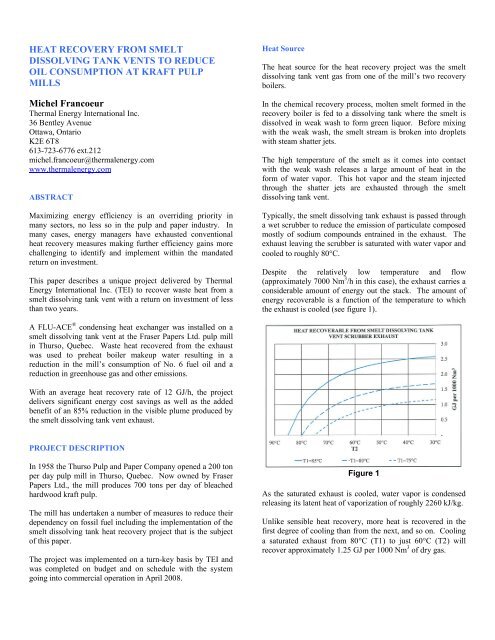
Despite the relatively low temperature and flow<br />
(approximately 7000 Nm 3 /h in this case), the exhaust carries a<br />
considerable amount of energy out the stack. The amount of<br />
energy recoverable is a function of the temperature to which<br />
the exhaust is cooled (see figure 1).<br />
Figure 1<br />
As the saturated exhaust is cooled, water vapor is condensed<br />
releasing its latent heat of vaporization of roughly 2260 kJ/kg.<br />
Unlike sensible heat recovery, more heat is recovered in the<br />
first degree of cooling than <strong>from</strong> the next, and so on. Cooling<br />
a saturated exhaust <strong>from</strong> 80C (T1) to just 60C (T2) will<br />
recover approximately 1.25 GJ per 1000 Nm 3 of dry gas.
<strong>Heat</strong> Sink<br />
Any heat user below 60C could be considered for a smelt<br />
dissolving tank heat recovery application. These include:<br />
process makeup water;<br />
boiler makeup water;<br />
white water circuit;<br />
building / machine makeup air; and,<br />
boiler combustion air.<br />
In this case, boiler makeup water was chosen for its relatively<br />
low seasonal temperature profile of 35C to 55C. Also, the<br />
average flow of over 2000 L/min was sufficient to use all of<br />
the heat recoverable <strong>from</strong> the smelt dissolving tank vent.<br />
The boiler makeup water was heated through a secondary<br />
plate and frame heat exchanger installed on the FLU-ACE ®<br />
water circuit (see figure 2).<br />
System Maintenance<br />
Figure 2<br />
The possibilities of corrosion and/or the formation of scale due<br />
to pH levels and the residual sodium salts in the scrubber<br />
exhaust were carefully considered in the design of the heat<br />
recovery system.<br />
An analysis of the anticipated water chemistry was done in<br />
consultation with Hercules, the mill’s chemical supplier.<br />
The results of the analysis pointed to a low risk of slow<br />
scaling in the system. Conservatively, allowances for manual<br />
and chemical cleaning of heat exchange surfaces were made.<br />
An inspection of the FLU-ACE ® internals was conducted after<br />
six months of operation and the wetted heat exchange surfaces<br />
showed no signs of fouling. Based on the operation of the<br />
system to date and periodic water sampling, it is anticipated<br />
that any maintenance (if required) can be accommodated<br />
during regular scheduled plant maintenance shutdowns.<br />
Based on this first inspection, regular packing cleaning may<br />
not be necessary at all.<br />
Installation<br />
All mechanical and electrical tie-in work was executed during<br />
the mill’s planned maintenance shutdown.<br />
The tie-in to the smelt dissolving tank scrubber exhaust was<br />
done by replacing a section of the existing stack with a<br />
prefabricated double-tee section. The new section was<br />
installed with an automated diverting damper between the<br />
inlet and outlet connections and two manual FLU-ACE ®<br />
isolation dampers.<br />
Similarly, a prefabricated section of pipe with diverting and<br />
isolation valves was installed in the boiler makeup water line<br />
downstream of the existing water softeners and upstream of<br />
the de-aerator.<br />
Due to the space restrictions associated with this retrofit<br />
project, the FLU-ACE ® heat recovery tower was fabricated<br />
and installed in several sections spanning the 6 th , 7 th and 8 th<br />
floors of the recovery boiler building.<br />
These floors and mezzanines provide access for maintenance<br />
around the sump area, diverting and isolation dampers, tower<br />
internals section and exhaust fan.<br />
The liquid-to-liquid heat exchanger was installed on the<br />
ground floor of the boiler plant alongside the new water<br />
circulating pumps.<br />
Instrumentation and major equipment were selected to meet<br />
the mill’s standard in order to facilitate maintenance and make<br />
use of existing spare parts inventories.<br />
Commercial Terms<br />
This project was implemented under TEI’s <strong>Thermal</strong> AUD<br />
(Alternate Utility Delivery) Program.<br />
Under this program, the equipment is owned and operated by<br />
TEI over a term of several years. Over the term of the<br />
agreement, the recovered heat is metered and charged on a<br />
$/GJ rate basis that provides a significant energy cost saving<br />
to the user.<br />
Under this program, the project delivers an immediate benefit<br />
to the user without having to spend any internal capital.<br />
RESULTS<br />
Operation and Performance<br />
The system was put into commercial operation on April 11 th<br />
2008 and in its first nine months of operation the system has<br />
operated reliably and to specification.
The smelt dissolving tank vent exhaust is being cooled to<br />
within 2C of the boiler makeup water temperature resulting in<br />
an average heat recovery rate of 12 GJ/h or 1.7 GJ per 1,000<br />
Nm 3 of exhaust.<br />
The system has operated with only the regular required<br />
maintenance associated with a circulating pump, exhaust fan,<br />
and instrumentation common to pulp mill operation.<br />
Conclusions<br />
Provided there is a liquid or air stream at or below 60C that<br />
can benefit <strong>from</strong> incremental heating, <strong>Thermal</strong> <strong>Energy</strong><br />
International Inc. can provide a heat recovery solution around<br />
the smelt dissolving tank vent exhaust.<br />
Fouling (corrosion and scaling) can be controlled and<br />
managed, if not eliminated.<br />
<strong>Heat</strong> recovery rates of up to 2.5 GJ per 1,000 Nm 3 of exhaust<br />
are achievable at a return on investment of less than two years.