Orifice Plates - Prisma Instruments
Orifice Plates - Prisma Instruments
Orifice Plates - Prisma Instruments

You also want an ePaper? Increase the reach of your titles
YUMPU automatically turns print PDFs into web optimized ePapers that Google loves.
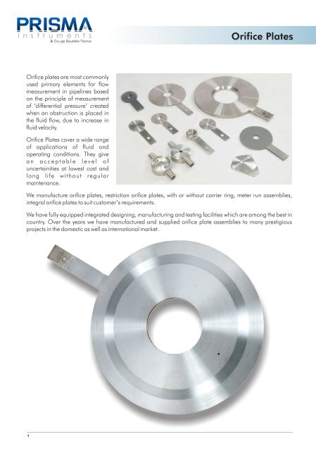
<strong>Orifice</strong> plates are most commonly<br />
used primary elements for flow<br />
measurement in pipelines based<br />
on the principle of measurement<br />
of ‘differential pressure’ created<br />
when an obstruction is placed in<br />
the fluid flow, due to increase in<br />
fluid velocity.<br />
<strong>Orifice</strong> <strong>Plates</strong> cover a wide range<br />
of applications of fluid and<br />
operating conditions. They give<br />
a n a c c e p t a b l e l e v e l o f<br />
uncertainities at lowest cost and<br />
long life without regular<br />
maintenance.<br />
<strong>Orifice</strong> <strong>Plates</strong><br />
We manufacture orifice plates, restriction orifice plates, with or without carrier ring, meter run assemblies,<br />
integral orifice plates to suit customer’s requirements.<br />
We have fully equipped integrated designing, manufacturing and testing facilities which are among the best in<br />
country. Over the years we have manufactured and supplied orifice plate assemblies to many prestigious<br />
projects in the domestic as well as international market.<br />
4
<strong>Orifice</strong> <strong>Plates</strong><br />
Specifications<br />
Design : Conforms to ISA RP 3.2 , DIN 1952 , BS 1042, ISO-5167<br />
Types : Square edge concentric, Quadrant edged, Conical entrance, Eccentric, Segmental<br />
Plate material : SS304 , SS316 , SS316L as standard. Hastelloy-C , Monel , PP , PVC , PTFE<br />
coated , etc. can be given on request.<br />
<strong>Orifice</strong> Bore : In accordance with ISO-5167, BS-1042, ASME MFC 3M, R.W.Miller,<br />
L.K.Spink, AGA-3<br />
Tab Plate : In the same material as plate & is welded to orifice plate. Tab plate integral to the<br />
<strong>Orifice</strong> plate (i.e. without welding) can also be offered as a special case.<br />
Vent / Drain : Vent or Drain holes are provided as per customer’s requirement. The diameter of the<br />
vent or drain holes are as per ISA RP 3.2<br />
Flange Union : Weld neck, Slip on, Threaded, Socket welded with RF or RTJ facing <strong>Orifice</strong><br />
flanges are in accordance with ANSI B16.36 with minimum flange rating of 300#<br />
for sizes up to 8” or male - female flanges in accordance with ANSI B16.5.<br />
Pressure Tappings : Corner tappings are recommended for sizes upto 1 ½”; Flange taps from 2" to 16" ;<br />
D – D/2 taps for higher sizes.<br />
Gasket : CAF as per IS: 2712 Gr 0/1 , SS spiral wound + CAF , SS spiral wound + Grafoil,<br />
SS spiral wound + PTFE are normally supplied as per process requirement. Other<br />
materials available on request.<br />
For RTJ flanges , the plate is fixed on the plate holder. The plate holder is in Soft Iron<br />
material & acts as a gasket .<br />
Studs / Nuts : ASTM A193 Gr.B7/A-194 Gr.2H as standard, Other material on request.<br />
Jack Screw : ASTM A193 Gr.B7/A-194 Gr.2H as standard, Other material on request.<br />
t 5
Types of <strong>Orifice</strong> <strong>Plates</strong><br />
Square Edged Concentric<br />
These are most commonly used for flow<br />
measurement. This has special features such as<br />
simple structures, high accuracy, and ease of<br />
installation & replacement. The orifice plates are<br />
correctly finished to the dimensions, surface<br />
roughness, and flatness to the applicable standard.<br />
These plates are recommended for clean liquids,<br />
gases & steam flow, when the Reynold number<br />
7<br />
ranges from 10000 to 10 .<br />
6<br />
Segmental<br />
Vent Hole<br />
Drain Hole<br />
Vent Hole<br />
(Optional)<br />
Segmental orifice plates are most<br />
useful where there are substantial<br />
entrained water or air and also if<br />
there are suspension in the fluids.<br />
This avoids build up in front of the<br />
orifice plate. The orifice hole is<br />
placed at the bottom for gas<br />
service and top for liquids.<br />
Eccentric<br />
The inlet edge of the bore of<br />
this orifice plate is rounded to<br />
a quarter circle. This orifice<br />
plate is usually used for viscous<br />
fluids & Reynolds number<br />
between 2000 to 10000.<br />
<strong>Orifice</strong> <strong>Plates</strong><br />
Vent Hole<br />
(Optional)<br />
Eccentricity<br />
For liquids containing solid particles that are likely<br />
to sediment or for vapors likely to deposit water<br />
condensate, this orifice plate is used with its<br />
eccentric bore bottom flush with the bottom of the<br />
piping inside surface so that the sedimentation of<br />
such inclusions are avoided. Likewise, for gases or<br />
vapors, it may be installed with its eccentric bore top<br />
flush with the ID of the piping to avoid stay of gas or<br />
vapor in its vicinity.<br />
Quadrant Edge Conical Entrance<br />
These conical entrance orifice<br />
plates are used for low Reynolds<br />
number in the range of 80 to<br />
2000 and give more constant or<br />
predictable discharge coefficient.<br />
At lower Reynolds numbers, the<br />
discharge coefficient of square<br />
edge orifice plate may change by<br />
as much as 30%. These are more<br />
usable for viscous service.
<strong>Orifice</strong> Assemblies<br />
Typical assemblies<br />
WNRF Flange<br />
<strong>Orifice</strong> Assembly with WNRF<br />
Flange & Flange Taps<br />
SORF Flange<br />
Pipe<br />
<strong>Orifice</strong> Plate<br />
25.4<br />
<strong>Orifice</strong> Plate<br />
<strong>Orifice</strong> Assembly with SORF<br />
Flange & Flange Taps<br />
ORIFICE PLATE WITH WELD<br />
NECK FLANGE UNION<br />
The weld neck flange is normally<br />
referred to as “ high Hub” flange. It is<br />
designed to transfer stresses to the<br />
pipe, thereby reducing high stress<br />
concentrations at the base of the<br />
flange. The pressure tappings are<br />
provided through the flangewhich arte<br />
at a distance of 1” from the face of the<br />
plate (shown in the drawing attached).<br />
Weld neck flanges are prefered where<br />
radiography on welding is involved.<br />
ORIFICE PLATE WITH SLIP ON FLANGE UNION<br />
The slip on flange has a low hub because the pipe slips into the flange prior to<br />
welding. It is welded both from inside and out to provide sufficient strength and<br />
prevent leakage. The slip on flanges are bored slightly larger than the OD of the<br />
matching pipe.<br />
ORIFICE PLATE WITH MALE-FEMALE CARRIER RING AND FLANGED UNION<br />
The construction is similar to the than 2”). Carrier rings are also assemblies are recommended<br />
above except male-female carrier available for bigger sizes on request. which employ upstream and<br />
ring is provided to facilitate pressure Carrier ring machined from single downstream straight lengths. The<br />
tapping through it (corner tapping). block is also offered in place of end connection in such case can be<br />
This construction is generally used male-female carrier. For better plain (suitable for welding) or<br />
for lower line sizes (normally less accuracy, honed meter run flanged.<br />
<strong>Orifice</strong> Plate with Carrier<br />
Ring & Flange Union<br />
Pipe<br />
SORF Flange<br />
<strong>Orifice</strong> Plate<br />
CARRIER RING<br />
7
8<br />
SIZE<br />
SAME AS SIZE 1/4" TO 78"<br />
SAME AS SCH<br />
SAME AS SCH<br />
SAME AS SCH<br />
SAME AS SCH<br />
SAME AS SCH<br />
SAME AS SCH<br />
SAME AS SCH<br />
SAME AS SCH<br />
SAME AS SCH<br />
SAME AS SCH<br />
WNF<br />
SOF<br />
SWF<br />
SCR<br />
RTJ<br />
LTG<br />
LJ<br />
SAME AS RATING<br />
SAME AS RATING<br />
SAME AS RATING<br />
SAME AS RATING<br />
SAME AS RATING<br />
SAME AS RATING<br />
FL<br />
RD<br />
CO<br />
PI<br />
NP<br />
BS<br />
SW<br />
A5<br />
F6<br />
F6L<br />
F4<br />
F4L<br />
F5<br />
F11<br />
F22<br />
SPECIFY<br />
PIPE SCH<br />
5<br />
10<br />
20<br />
40<br />
60<br />
80<br />
120<br />
160<br />
XS<br />
XXS<br />
FLANGE TYPE<br />
RATING<br />
WNRF<br />
SORF<br />
SWRF<br />
SCREWED<br />
WNRTJ<br />
WNLTG<br />
LAP JOINT<br />
150#<br />
300#<br />
600#<br />
900#<br />
1500#<br />
2500#<br />
TAPPING TYPE<br />
FLANGE<br />
RADIUS<br />
CORNER<br />
PIPE<br />
PROCESS CONNECTION<br />
NPT (F)<br />
BSP (F)<br />
SW<br />
FLANGE MATERIAL<br />
ASTM A105<br />
A182 F316<br />
A182 F316L<br />
A182 F304<br />
A182 F304<br />
A182 F5<br />
A182 F11<br />
A182 F22<br />
OTHER<br />
Ordering Guide<br />
<strong>Orifice</strong> Assembly<br />
CE<br />
HS<br />
HI<br />
NACE<br />
IBR<br />
H2<br />
O2<br />
WCAL<br />
B7<br />
B8<br />
B16<br />
B7M<br />
B8M<br />
SPECIAL<br />
CE<br />
H2S<br />
HIC<br />
NACE<br />
IBR<br />
H2 SERVICE<br />
O2 CLEANING<br />
WET CALLIBRATION<br />
STUD NUT / JACK SCREW<br />
6GR<br />
6CA<br />
4GR<br />
4CA<br />
OCT<br />
PT<br />
NEO<br />
BR<br />
SPECIFY<br />
6/ 6L<br />
4/ 4L<br />
MO<br />
HC<br />
PF<br />
PV<br />
PP<br />
SPECIFY<br />
SEC<br />
QEC<br />
ECC<br />
SEG<br />
COE<br />
RO<br />
SAME AS THK<br />
SAME AS THK<br />
SAME AS THK<br />
SAME AS THK<br />
SPECIFY<br />
A193 Gr. B7/ Gr.2H<br />
A193 Gr. B8/ Gr.8<br />
A193 Gr. B16/ Gr.16<br />
A193 Gr. B7M/ Gr.2HM<br />
A193 Gr. B8M/ Gr.8M<br />
GASKET<br />
PLATE MATERIAL<br />
PLATE TYPE<br />
SW SS316 + GRFL<br />
SW SS316 + CAF<br />
SW SS304 + GRFL<br />
SW SS304 + CAF<br />
OCTAL RING<br />
PTFE<br />
NEOPRENE<br />
BUTYL RUBBER<br />
OTHER<br />
SS316/ 316L<br />
SS304/ 304L<br />
MONEL<br />
HASTELLOY - C<br />
PTFE<br />
PVC<br />
POLY PROPYLENE<br />
OTHER<br />
PLATE THICKNESS<br />
SQUARE EDGE<br />
QUDRANT EDGE<br />
ECCENTRIC<br />
SEGMENTAL<br />
CONICAL ENTRANCE<br />
RESTRICTION<br />
3.18mm<br />
6.35mm<br />
9.52mm<br />
12.70mm<br />
OTHER<br />
Note: 1. Upto 6" size, flanges will be used of ANSI B16.36 and from 8" & above flanges will be used of ANSI B 16.5<br />
2. Drain hole for gas service & vent hole for liquid service will be provided as per requirement.<br />
3. Other than above information customer has to provide process data as on page no. 32<br />
4. Default process connection size is 1/2" other than this (e.g. 3/4" or 1"), please specify.<br />
5. If carrier ring is required, only carrier ring material should be provided extra to the above information.
<strong>Orifice</strong> Plate Assemblies with RTJ Holder<br />
The Plate Holder Assembly is a combination of plate<br />
holder and an orifice plate designed for ring tongue<br />
joint (RTJ) flanges. The plate holder has a function of<br />
holding the orifice plate and also a function as a<br />
gasket to prevent leakage of the process fluid. The<br />
plate holder has a oval or octagonal ring for<br />
mounting between ring tongue joint flanges. This<br />
metallic sealing system is applicable to a fluid of high<br />
temperature and high pressure. The pressure<br />
tapping system normally is of the flange tap type.<br />
<strong>Orifice</strong> plate is screwed to the plate holder. Generally<br />
the plate holder is of soft iron material. The <strong>Orifice</strong><br />
plate is available in standard material such as<br />
SS316, SS304, SS316L, Monel, Hastelloy-C, etc.<br />
Other materials are available on request. The plate<br />
holder along with the orifice plate can be also<br />
machined from one piece.<br />
RTJ holder material is selected so that the RTJ holder<br />
hardness is less than that of flange hardness.<br />
<strong>Orifice</strong> Plate<br />
Plate with Plate Holder<br />
mounted in between RTJ Flanges<br />
WNRTJ Flange Plate<br />
Plate Holder<br />
and Gasket<br />
Integral RTJ Integral RTJ <strong>Orifice</strong> Plate<br />
with Female Groove with RTJ Holder<br />
9<br />
Plate Holder
The restriction orifices are used for reducing<br />
fluid pressure and are designed somewhat<br />
different from the orifice plates that are used<br />
for measuring flow rates. They are designed to<br />
slip between the piping flanges.<br />
Restriction <strong>Orifice</strong><br />
While single restriction orifices are often sufficient to meet the requirements, there are<br />
situations where limitations arise due to process conditions making the single restriction<br />
orifices unacceptable. In such situations, use of multiple restriction in series is a better<br />
solution.<br />
The foremost consideration for the case of multiple restriction is the pressure drop. This<br />
applies whether or not the fluid is liquid or vapor/gas. Higher pressure drop implies higher<br />
velocities resulting in vibration and noise problems.<br />
The other consideration is not just about maximum permitted pressure drop and this is<br />
particularly for gas flow. If the process condition indicates that critical flow will occur with the<br />
use of single restriction plate, care should be exercised to avoid operating well beyond the<br />
critical pressure drop. Critical implies a pressure drop across the device exceeding 50 percent<br />
of the absolute upstream pressure at which point sonic velocity is reached.<br />
Construction of Multistage <strong>Orifice</strong> Assembly comprises of multiple restriction orifice<br />
plates separated by a distance of one pipe diameter and welded with the pipes in<br />
between them. End connection is either suitable for butt welding or with end<br />
flanges.<br />
10<br />
Multiple Restriction <strong>Orifice</strong> Assembly
Integral Meter Run Assembly<br />
Integral Flow <strong>Orifice</strong> Assembly is used when assembly cannot be used for process temperatures<br />
Differential Pressure Transmitter has to be directly above 120 Degrees Centigrade.<br />
mounted on the orifice assembly. This eliminates<br />
cost of installation of Differential Pressure<br />
Transmitter with impulse piping up to the orifice<br />
assembly. The transmitter is mounted on the orifice<br />
The assembly consists of a orifice plate between two<br />
integral blocks having corner taps. Generally meter<br />
run pipe is recommended with upstream length of<br />
750mm and downstream length of 250mm. The<br />
assembly through a 3/5 Valve H-type manifold.<br />
Available with line sizes of 2" & below. However due<br />
to process temperature limits of the transmitter, this<br />
DP Transmitter<br />
Integral Block<br />
pipes are welded to the blocks with end flanges.<br />
Manifold Valve<br />
Integral <strong>Orifice</strong> Assembly, Manifold valve, DP transmitter & end flanges<br />
11
Advantages of using Integral Meter run assembly:<br />
Use of an integral orifice flow meter will eliminate the three measurement inaccuracies<br />
recorded in small orifice line installations.<br />
The Integral <strong>Orifice</strong> honed body reduces ID uncertainty<br />
By inserting precision bored upstream and downstream sections of pipe, the velocity profile<br />
distortion due to pipe roughness is reduced.<br />
The self-centering design of the Integral <strong>Orifice</strong> Plate eliminates plate misalignment.<br />
Improves reliability and maintenance costs<br />
The integral orifice flow meter eliminates impulse lines, reducing leak points by over 50% and<br />
decrease start-up time due to the flexibility of numerous process connection options. The<br />
direct mount design minimizes line plugging by eliminating long lines, small-bore ports, and<br />
crevices while providing consistently reliable installations.<br />
Accuracy up to ±0. 5% of volumetric flow rate<br />
Integral manifold head allows direct mounting of DP transmitters<br />
Ideal fluid types: liquid, gas, and steam<br />
12<br />
End Flange<br />
DP Transmitter<br />
Manifold Valve<br />
Oval Flange<br />
Nipple<br />
Flange Union<br />
Integral Meter Run Assembly<br />
1 Mtr.<br />
Integral <strong>Orifice</strong> Assembly with<br />
flange union, manifold valve,<br />
DP transmitter & end flanges
Ordering Guide<br />
Integral Meter Run Assembly<br />
SIZE<br />
SAME AS SIZE 1/2" TO 2"<br />
SAME AS SCH<br />
SAME AS SCH<br />
SAME AS SCH<br />
SAME AS SCH<br />
SAME AS SCH<br />
6/ 6L<br />
4/ 4L<br />
SPECIFY<br />
A1B<br />
P4/ P4L<br />
P6/ P6L<br />
SPECIFY<br />
PT<br />
SPW<br />
SPECIFY<br />
PIPE SCH<br />
5<br />
10<br />
40<br />
80<br />
160<br />
PLATE MATERIAL<br />
SS316/ 316L<br />
SS304/ 304L<br />
OTHER<br />
PIPE MATERIAL<br />
GASKET<br />
A 106 Gr.B<br />
TP304/ 304L<br />
TP316/ 316L<br />
OTHER<br />
PTFE<br />
SPIRAL WND<br />
OTHER<br />
Note: 1. Use the end flange details as described in orifice ordering information.<br />
2. Other than above information customer has to provide process data as on page no. 32<br />
3. If manifold valve is required then please provide detail specifications for the same.<br />
CE<br />
HS<br />
HI<br />
NACE<br />
PWHT<br />
H2<br />
O2<br />
WCAL<br />
SPECIFY<br />
MVRQ<br />
MVNRQ<br />
KFRQ<br />
KFNRQ<br />
IA5<br />
I6/ I6L<br />
I4/ I4L<br />
SPECIFY<br />
SPECIAL<br />
MANIFOLD VALVE<br />
CE<br />
H2S<br />
HIC<br />
NACE<br />
PWHT<br />
H2 SERVICE<br />
O2 CLEANING<br />
WET CALLIBRATION<br />
OTHER<br />
REQUIRED<br />
NOT REQUIRED<br />
KIDNEY FLANGE<br />
REQUIRED<br />
NOT REQUIRED<br />
INT BODY MATERIAL<br />
13<br />
ASTM A105<br />
F316/ 316L<br />
F304/ 304L<br />
OTHER
Meter runs are supplied as a complete unit of<br />
normally 1M length to ensure the necessary<br />
straight pipe length to achieve highest possible<br />
efficiency.<br />
These are available with line sizes mostly below<br />
50mm with corner tap.<br />
These are used for the measurement of small flow<br />
rates precisely where high accuracy of flow rates is<br />
required.<br />
Types of Meter Runs:<br />
1. <strong>Orifice</strong> Flange union with Meter -run.<br />
2. <strong>Orifice</strong> flange union with Carrier ring &<br />
Meter –run.<br />
Generally Meter-run pipe is recommended with<br />
upstream length of 750mm and downstream<br />
length of 250mm.<br />
Meter runs sizes above 50mm are also available<br />
as per the customers or process requirements.<br />
MOC: <strong>Orifice</strong> Plate in SS 316, SS 304 & other on<br />
request.<br />
End Connection: Socket Weld, Screwed and<br />
Flanged ends with meter run piping suitable to<br />
ANSI, IS & DIN flanges<br />
14<br />
Meter Runs<br />
X<br />
X