A certified reference material for the scratch test - Estudo Geral
A certified reference material for the scratch test - Estudo Geral
A certified reference material for the scratch test - Estudo Geral

You also want an ePaper? Increase the reach of your titles
YUMPU automatically turns print PDFs into web optimized ePapers that Google loves.
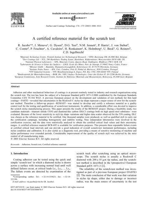
Surface and Coatings Technology 174 –175 (2003) 1008–1013<br />
A <strong>certified</strong> <strong>reference</strong> <strong>material</strong> <strong>for</strong> <strong>the</strong> <strong>scratch</strong> <strong>test</strong><br />
a, a b b c c d<br />
R. Jacobs *, J. Meneve , G. Dyson , D.G. Teer , N.M. Jennett , P. Harris , J. von Stebut ,<br />
d e f g g h h<br />
C. Comte , P. Feuchter , A. Cavaleiro , H. Ronkainen , K. Holmberg , U. Beck , G. Reiners ,<br />
C.D. Ingelbrechti aMaterials<br />
Technology Centre, Flemish Institute <strong>for</strong> Technological Research – VITO, Boeretang 200, B-2400 Mol, Belgium<br />
bTeer<br />
Coatings Ltd – TCL, 290 Hartlebury Trading Estate, Hartlebury, Kidderminster, Worcestershire DY10 4JB, UK<br />
cNational<br />
Physical Laboratory – NPL, Materials Centre, Queens Road, Teddington, Middlesex TW11 0LW, UK<br />
d Laboratoire de Science et Genie ´ des Surfaces – LSGS, Ecole des Mines, Parc de Saurupt, F-54042 Nancy Cedex, France<br />
eMossner ¨ Gmbh – Hamodia, ¨ Diamantwerkzeugfabrik, Kelterstrasse 82, D-75179 P<strong>for</strong>zheim, Germany<br />
fInstituto<br />
Pedro Nunes – IPN, Univ. Coimbra, Polo II, Pinhal de Marrocos, 3030 Coimbra, Portugal<br />
gVTT<br />
Industrial Systems – VTT, Metallimiehenkuja 6, Espoo, P.O. Box 1702, FIN-02044 VTT, Finland<br />
hBundesanstalt fur ¨ Material<strong>for</strong>schung – BAM, Div. VIII.2 Surface Technologies, Unter den Eichen 87, D-12200 Berlin, Germany<br />
iEuropean<br />
Commission, Joint Research Centre, Institute <strong>for</strong> Reference Materials and Measurements, Retieseweg, B-2440 Geel, Belgium<br />
Abstract<br />
Adhesion and o<strong>the</strong>r mechanical behaviour of coatings is at present routinely <strong>test</strong>ed in industry and research organisations using<br />
<strong>the</strong> <strong>scratch</strong> <strong>test</strong>. The <strong>test</strong> has been <strong>the</strong> subject of a European Standard prEN 1071-3:2000 established by <strong>the</strong> European Standards<br />
Committee CEN TC184 WG5. A previous European project on <strong>the</strong> development and validation of <strong>test</strong> methods <strong>for</strong> thin hard<br />
coatings—FASTE—revealed that uncertainties in <strong>the</strong> Rockwell C stylus tip shape represent a major source of error <strong>for</strong> <strong>the</strong> <strong>scratch</strong><strong>test</strong><br />
method. There<strong>for</strong>e a follow-up project—REMAST—was started to develop and certify a <strong>reference</strong> <strong>material</strong> as a quality<br />
control tool <strong>for</strong> <strong>the</strong> <strong>test</strong>ing and qualification of <strong>scratch</strong>-<strong>test</strong> instruments. In addition, a considerable ef<strong>for</strong>t was devoted to improve<br />
<strong>the</strong> <strong>scratch</strong> stylus manufacturing process. This paper presents <strong>the</strong> results of <strong>the</strong> REMAST project. During a feasibility study, two<br />
candidate <strong>material</strong>s—titanium nitride (TiN) and diamond-like carbon (DLC) coatings both on high speed steel substrates—were<br />
evaluated. Because of <strong>the</strong> lower sensitivity to styli tip shape variations and higher data scatter observed <strong>for</strong> <strong>the</strong> TiN coating, DLC<br />
was chosen as <strong>the</strong> <strong>reference</strong> <strong>material</strong> to be <strong>certified</strong>. One thousand samples were produced, as well as qualified styli to carry out<br />
<strong>the</strong> certification campaign, including homogeneity and stability <strong>test</strong>ing. Nine independent laboratories were involved in <strong>the</strong><br />
certification exercise, and <strong>the</strong> data were statistically analysed to obtain <strong>the</strong> <strong>certified</strong> critical load values and <strong>the</strong>ir uncertainty<br />
ranges. A <strong>certified</strong> <strong>reference</strong> <strong>material</strong> BCR-692 is available <strong>for</strong> verification purposes. This presents three repeatable failure events<br />
at <strong>certified</strong> critical load intervals and can provide a good indication of overall <strong>scratch</strong>-<strong>test</strong> instrument per<strong>for</strong>mance, including<br />
stylus condition and calibration. It is also useful as a diagnostic tool, providing a means of sensitive monitoring of machine and<br />
stylus per<strong>for</strong>mance over extended periods. Considerable improvement of <strong>the</strong> quality of <strong>scratch</strong> styli was achieved by <strong>the</strong> strict<br />
control of all manufacturing steps.<br />
2003 Elsevier Science B.V. All rights reserved.<br />
Keywords: Adhesion; Scratch <strong>test</strong>; Certified <strong>reference</strong> <strong>material</strong><br />
1. Introduction<br />
Coating adhesion can be <strong>test</strong>ed using <strong>the</strong> quick and<br />
simple ‘<strong>scratch</strong> <strong>test</strong>’ in which a diamond stylus is drawn<br />
across a surface with increasing normal load until well<br />
defined failures occur, at critical loads Lc , Lc ,«, Lc.<br />
1 2 n<br />
The failure events are detected by examination of <strong>the</strong><br />
*Corresponding author. Tel.: q32-14-335623; fax: q32-14-<br />
321186.<br />
E-mail address: ria.jacobs@vito.be (R. Jacobs).<br />
0257-8972/03/$- see front matter 2003 Elsevier Science B.V. All rights reserved.<br />
doi:10.1016/S0257-8972Ž03.00470-5<br />
<strong>scratch</strong> track after <strong>scratch</strong>ing using an optical microscope.<br />
The <strong>scratch</strong> stylus is usually a Rockwell C<br />
diamond with 200"10 mm tip radius, and <strong>the</strong> <strong>scratch</strong><strong>test</strong><br />
method is described in <strong>the</strong> (prospective) European<br />
Standard prEN 1071-3 w1x.<br />
The reliability of <strong>the</strong> <strong>scratch</strong>-<strong>test</strong> method was investigated<br />
as part of a previous European project (FASTE)<br />
w2x. The main conclusion of that work was that variation<br />
in stylus tip shape, ei<strong>the</strong>r due to damage or incorrect<br />
radius, was <strong>the</strong> main source of uncertainty in <strong>the</strong> <strong>test</strong>
R. Jacobs et al. / Surface and Coatings Technology 174 –175 (2003) 1008–1013<br />
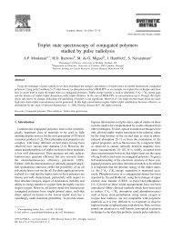
Fig. 1. Failure events associated with (a) Lc ; (b) Lc and (c) Lc (S.D., <strong>scratch</strong> direction).<br />
1 2 3<br />
method. The REMAST project described here w3x was<br />
<strong>the</strong>re<strong>for</strong>e set up with <strong>the</strong> objective of developing and<br />
certifying a ‘real world’ <strong>reference</strong> <strong>material</strong> <strong>for</strong> <strong>the</strong><br />
verification of <strong>the</strong> proper functioning of <strong>scratch</strong>-<strong>test</strong><br />
instruments by detecting deviations in stylus tip shape<br />
and errors in load or displacement calibrations or o<strong>the</strong>r<br />
instrument malfunctions. Secondary objectives were<br />
improvements in stylus manufacturing and characterisation<br />
methods, because FASTE had shown that many<br />
styli in use deviated significantly from those specified<br />
w4x <strong>for</strong> <strong>the</strong> <strong>scratch</strong> <strong>test</strong>ing method.<br />
2. Feasibility study and selection of candidate<br />
<strong>material</strong><br />
Two candidate coating types, diamond-like carbon<br />
(DLC) and TiN, both on high speed steel substrates,<br />
were selected <strong>for</strong> <strong>the</strong> feasibility study. TiN is a very<br />
widely used and established coating type while DLC<br />
coatings represent an important emerging technology.<br />
1009<br />
Scratch <strong>test</strong> styli were ground according to ISO specifications<br />
w4x.<br />
Three <strong>scratch</strong> <strong>test</strong> failure events were identified <strong>for</strong><br />
DLC (Fig. 1): <strong>for</strong>ward chevron cracks at <strong>the</strong> borders of<br />
<strong>the</strong> <strong>scratch</strong> track (Lc ), <strong>for</strong>ward chevron cracks at <strong>the</strong><br />
1<br />
borders of <strong>the</strong> <strong>scratch</strong> track accompanied by interfacial<br />
spallation (Lc ) and gross interfacial shell-shaped spal-<br />
2<br />
lation (Lc ). Four failure events were identified <strong>for</strong> TiN<br />
3<br />
coatings: longitudinal cracks at <strong>the</strong> track edges (Lc ),<br />
1<br />
semicircular coating cracks inside <strong>the</strong> <strong>scratch</strong> tracks<br />
(Lc ), cohesive chipping at <strong>the</strong> tracks edges (Lc ) and<br />
2 3<br />
spallation at <strong>the</strong> track edges (Lc ).<br />
4<br />
Homogeneity and stability <strong>test</strong>ing, completed with<br />
data on stylus wear, allowed a comparison of <strong>the</strong> two<br />
candidate coatings.<br />
Extensive homogeneity <strong>test</strong>ing was per<strong>for</strong>med to<br />
investigate potential differences within samples and<br />
between samples originating from different locations in<br />
<strong>the</strong> reactor or different coating deposition batches. The<br />
DLC samples showed lower scatter in critical loads
1010 R. Jacobs et al. / Surface and Coatings Technology 174 –175 (2003) 1008–1013<br />
compared to <strong>the</strong> TiN samples, indicating better homogeneity<br />
or more easily detected failure events. Chemical<br />
heterogeneity was studied by XPS, Auger and GD-OES.<br />
No significant heterogeneity was detected, nei<strong>the</strong>r <strong>for</strong><br />
DLC nor TiN.<br />
A series of accelerated degradation <strong>test</strong>s was carried<br />
out to determine stability during cycled exposure to high<br />
and low temperature. In addition, medium-term stability<br />
<strong>test</strong>ing after storage in laboratory air <strong>for</strong> 6 months was<br />
carried out. No evidence of instability was detected <strong>for</strong><br />
both coating types.<br />
Wear experiments revealed that <strong>the</strong> stylus suffered<br />
from significant wear when <strong>scratch</strong>ing <strong>the</strong> TiN coated<br />
sample after only 50 <strong>scratch</strong>es, while <strong>the</strong> expected<br />
lifetime of <strong>the</strong> stylus against DLC is over 400 <strong>scratch</strong>es.<br />
The most important factor taken into account was <strong>the</strong><br />
sensitivity of critical load to tip radius R relative to <strong>the</strong><br />
standard deviation of <strong>the</strong> data (DLcy(DRs)). The DLC<br />
was much superior in this respect, <strong>for</strong> all critical loads.<br />
However, <strong>the</strong> load range <strong>for</strong> DLC (up to approximately<br />
35 N) was half that of <strong>the</strong> TiN (up to 65 N)<br />
resulting in a smaller probe depth (4–6 mm), but this<br />
was considered sufficient <strong>for</strong> <strong>the</strong> evaluation of stylus<br />
shape, especially bearing in mind that ‘multi-mode’<br />
<strong>scratch</strong> <strong>test</strong>ing, now being developed w5x and likely to<br />
become <strong>the</strong> standard method in <strong>scratch</strong> <strong>test</strong>ing, will use<br />
lower loads than those generally used in current practice.<br />
On <strong>the</strong> basis of <strong>the</strong> above considerations DLC was<br />
selected as <strong>the</strong> coating to be used <strong>for</strong> <strong>the</strong> <strong>reference</strong><br />
<strong>material</strong>.<br />
3. Reference <strong>material</strong> and stylus production<br />
3.1. Production of <strong>the</strong> <strong>reference</strong> <strong>material</strong><br />
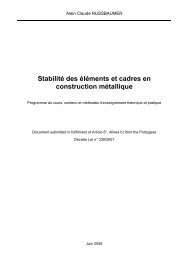
Eleven batches of PACVD DLC coated steel coupons<br />
3 30=30=5 mm of Bohler ¨ S790 powder metallurgy<br />
steel were prepared using <strong>the</strong> same method as in <strong>the</strong><br />
feasibility study. Fig. 2 shows <strong>the</strong> <strong>reference</strong> <strong>material</strong>.<br />
Specimens were randomly selected <strong>for</strong> fur<strong>the</strong>r <strong>test</strong>ing<br />
and certification purposes.<br />
3.2. Production of qualified styli<br />
It was essential <strong>for</strong> <strong>the</strong> certification exercise to use<br />
styli con<strong>for</strong>ming to <strong>the</strong> specifications <strong>for</strong> Rockwell C<br />
indenters w4x in order to reduce as far as possible<br />
variability in measured critical load values due to stylus<br />
irregularities or damage. There<strong>for</strong>e, improved positioning<br />
techniques were used during stylus manufacturing,<br />
combined with <strong>the</strong> selection of appropriate wheels <strong>for</strong><br />
preliminary grinding and polishing steps. Moreover,<br />
crystal orientations were checked by Laue diffraction<br />
be<strong>for</strong>e grinding. Tip radii and geometry were determined<br />
by an optical contour technique, knife-edge profilometry,<br />
interferometry and Twymann-Green interferometry. It<br />
Fig. 2. The <strong>reference</strong> <strong>material</strong> BCR-692.<br />
was found that <strong>the</strong> stylus tips often showed ‘nodes’ or<br />
local irregularities, with <strong>the</strong> consequence that stylus<br />
radius values depended on <strong>the</strong> tip area examined. Styli<br />
were allocated to individual laboratories <strong>for</strong> fur<strong>the</strong>r<br />
<strong>test</strong>ing and certification purposes.<br />
4. Certification of <strong>the</strong> <strong>reference</strong> <strong>material</strong><br />
4.1. Certified values and uncertainties<br />
The <strong>reference</strong> <strong>material</strong> was defined by a <strong>certified</strong><br />
critical load value (CV) and uncertainty (U c)<br />
<strong>for</strong> each<br />
<strong>scratch</strong> <strong>test</strong> failure. The <strong>certified</strong> value <strong>for</strong> each critical<br />
load is <strong>the</strong> mean of means of <strong>the</strong> sets of data obtained<br />
in <strong>the</strong> certification exercise, giving equal weight to each<br />
laboratory. The expanded uncertainty is calculated<br />
according to <strong>the</strong> method given in ISO 35 w6x:<br />
Ž .<br />
2 2 2 2 1y2<br />
c c bb bs ws<br />
U s"k sypqu qu qu , (1)<br />
where s is <strong>the</strong> standard deviation of <strong>the</strong> set means of<br />
c<br />
<strong>the</strong> certification data, p is number of accepted sets, u ,<br />
bb<br />
u and u are uncertainty components (as standard<br />
bs ws<br />
errors) related with heterogeneity (between-batches u ,<br />
bb<br />
between-samples u and within-samples u ) and k is a<br />
bs ws<br />
coverage factor.<br />
The uncertainty calculated above represents <strong>the</strong> variation<br />
in <strong>the</strong> critical load expected from <strong>material</strong> heterogeneity<br />
and <strong>the</strong> average measurement uncertainty of <strong>the</strong><br />
certification instruments. However, <strong>the</strong> exact critical load<br />
that an individual laboratory will obtain will be systematically<br />
offset from <strong>the</strong> <strong>certified</strong> mean value due to<br />
<strong>the</strong> specific instrument and stylus being used. The<br />
distribution of offsets arising from stylus effects (u )<br />
ss<br />
was estimated from a stylus sensitivity study. Linear<br />
regression techniques were used to determine <strong>the</strong> distribution<br />
of offsets arising from <strong>the</strong> use of different types<br />
of machines in <strong>the</strong> certification campaign. Note that all
R. Jacobs et al. / Surface and Coatings Technology 174 –175 (2003) 1008–1013<br />
Table 1<br />
Certified values (CV), uncertainties (U c),<br />
and uncertainty components<br />
(N)<br />
u bb u bs u ws s c p u ss u l CV U c<br />
Lc 1 0.40 0.49 0.55 1.72 18 1.05 0.8 13.6 "1.9<br />
Lc 2 0.44 0.49 0.53 2.31 18 2.26 1.11 17.0 "2.0<br />
Lc 3 0.8 0.81 1.30 1.78 14 1.34 2.11 28 "4<br />
The terms u and u have not been included in <strong>the</strong> calculation of<br />
ss l<br />
U . A coverage factor ks2 has been applied.<br />
c<br />
of <strong>the</strong> certification instruments met <strong>the</strong> requirements of<br />
prEN 1071-3 in terms of operation and calibration, but<br />
produced different critical load values, which are<br />
assumed to be as a result of differences in mechanism<br />
or compliance. This component (u ) was estimated from<br />
l<br />
<strong>the</strong> complete set of certification and control data made<br />
by a control lab with <strong>the</strong> same stylus as <strong>the</strong> participating<br />
lab.<br />
The decision to exclude <strong>the</strong> stylus (u ) and machine<br />
ss<br />
(u ) effects from <strong>the</strong> <strong>certified</strong> range is based on <strong>the</strong> fact<br />
l<br />
that <strong>the</strong>se are <strong>test</strong>-related ra<strong>the</strong>r than <strong>material</strong>-related<br />
factors, ra<strong>the</strong>r less well defined than <strong>the</strong> <strong>material</strong> properties,<br />
and may well change in future due to improvements<br />
in machine per<strong>for</strong>mance and stylus production or<br />
to redefinition of <strong>the</strong> range of acceptable styli. The<br />
<strong>certified</strong> range, based on <strong>the</strong> <strong>material</strong>s’ properties only,<br />
will not change. The terms u and u <strong>the</strong>re<strong>for</strong>e do not<br />
ss l<br />
appear in Eq. (1) above.<br />
4.2. Homogeneity of <strong>the</strong> <strong>reference</strong> <strong>material</strong><br />
An extensive homogeneity study was carried out in<br />
which 6 samples from each of <strong>the</strong> deposition batches<br />
were <strong>test</strong>ed (5 <strong>scratch</strong>es per sample). A parallel study<br />
was carried out <strong>test</strong>ing 3 samples from each batch (10<br />
<strong>scratch</strong>es per sample) <strong>for</strong> a more detailed examination<br />
of <strong>the</strong> ‘within-sample’ effect. Two-way ANOVA was<br />
<strong>the</strong>n carried out <strong>for</strong> each data set (33 samples and 66<br />
samples) to estimate <strong>the</strong> three uncertainty components<br />
(as standard uncertainties): between-batches u ,<br />
bb<br />
between-samples u and within-samples u <strong>for</strong> each<br />
bs ws<br />
failure event (Table 1). The real within-sample effect,<br />
cannot of course be separated from <strong>the</strong> natural scatter<br />
of <strong>the</strong> method (repeatability), which also makes a<br />
contribution to u .<br />
ws<br />
4.3. Certification data and control data<br />
The nine laboratories participating in <strong>the</strong> certification<br />
campaign used three different types of instrument (CSM<br />
Reve<strong>test</strong>, VTT Industrial Systems, Teer Coatings Ltd).<br />
The instrument calibration procedures, consistent with<br />
<strong>the</strong> requirements of prEN 1071-3, included verification<br />
of sample planarity, load and load rate, horizontal<br />
displacement and displacement rate. Each laboratory<br />
was supplied with 2 samples selected randomly from<br />
1011<br />
<strong>the</strong> entire production and one of <strong>the</strong> qualified styli. After<br />
calibration, each laboratory made 40 <strong>scratch</strong>es on each<br />
of <strong>the</strong> 2 samples with a load rate of 100 Nymin, starting<br />
load 5 N, maximum load 45 N and displacement rate<br />
of 10 mmymin. Critical loads Lc , Lc , Lc correspond-<br />
1 2 3<br />
ing to <strong>the</strong> well-defined failure events were corrected <strong>for</strong><br />
each of <strong>the</strong> calibration factors, and are used <strong>for</strong> calculation<br />
of <strong>the</strong> <strong>certified</strong> values, as given in Table 1.<br />
In addition, <strong>the</strong> control laboratory carried out a fur<strong>the</strong>r<br />
5 <strong>scratch</strong>es on each of <strong>the</strong> samples supplied to <strong>the</strong><br />
participants using, in each case, <strong>the</strong> same stylus used by<br />
<strong>the</strong> respective participant and ano<strong>the</strong>r 5 <strong>scratch</strong>es using<br />
a single ‘control stylus’. For each critical load, <strong>the</strong><br />
complete set of certification data and control data L is<br />
ijk<br />
modeled in terms of a <strong>reference</strong> value m, laboratoryy<br />
machine, stylus and sample offsets (L , R and S ,<br />
i j k<br />
respectively) and random measurement error e :<br />
ijk<br />
Lc smqL qR qS qe . (2)<br />
ijk i j k ijk<br />
under <strong>the</strong> assumptions that <strong>the</strong> sums of <strong>the</strong> off-sets<br />
2<br />
E(L i)sE(R j)sE(S k)sE(e ijk)s0, var(e ijk)ss<br />
, with<br />
2 s an (unknown) constant, and eijk independent. A<br />
regression analysis was carried out and <strong>the</strong> distribution<br />
of offsets from <strong>the</strong> regression fitting were evaluated.<br />
The standard deviation of <strong>the</strong> laboratory offsets distribution<br />
is an estimate of u l (Table 1). Note that this<br />
uncertainty component includes contributions both from<br />
<strong>the</strong> variations in <strong>the</strong> machines and variations in lab<br />
per<strong>for</strong>mance and <strong>the</strong>se two cannot be separated.<br />
4.4. Stylus sensitivity data<br />
A specific stylus sensitivity <strong>test</strong> was also carried out<br />
by <strong>the</strong> control laboratory, taking eight styli with radii in<br />
<strong>the</strong> range (200"10) mm, as required by ISO 6508-2<br />
w4x and making 9 <strong>scratch</strong>es with each one on a single<br />
sample. The only sources of variation in <strong>the</strong> results of<br />
this study are (a) <strong>the</strong> different styli and (b) scatter<br />
related to <strong>the</strong> precision of <strong>the</strong> <strong>test</strong>ing or to small<br />
differences in <strong>the</strong> coating across <strong>the</strong> single specimen<br />
used. These two components can be separated by a oneway<br />
ANOVA, allowing <strong>the</strong> distribution of critical load<br />
values arising from stylus effects u to be estimated. It<br />
ss<br />
was found that Lc appears to be more sensitive to<br />
2<br />
stylus radius (higher u ) than <strong>the</strong> o<strong>the</strong>r critical loads.<br />
ss<br />
Table 1 shows that <strong>the</strong> largest component of uncer-<br />
tainty <strong>for</strong> Lc and Lc is <strong>the</strong> stylus-related term u ,<br />
1 2 ss<br />
which confirms <strong>the</strong> high sensitivity of <strong>the</strong> <strong>test</strong> to stylus<br />
effects as observed in <strong>the</strong> FASTE program w2x. It should<br />
be remembered, of course, that <strong>the</strong> DLC coating was<br />
chosen specifically <strong>for</strong> its high sensitivity to stylus<br />
radius. Instrumentylaboratory effects (<strong>the</strong> u term) also<br />
l<br />
play a major role.
1012 R. Jacobs et al. / Surface and Coatings Technology 174 –175 (2003) 1008–1013<br />
5. Use of <strong>the</strong> <strong>certified</strong> <strong>reference</strong> <strong>material</strong> and <strong>the</strong><br />
‘Good Practice Guide’<br />
The <strong>certified</strong> <strong>reference</strong> <strong>material</strong> (CRM) can be used<br />
<strong>for</strong> two main purposes: (1) <strong>for</strong> verification of (calibrated)<br />
<strong>scratch</strong>-<strong>test</strong> instruments, giving a good indication of<br />
overall instrument per<strong>for</strong>mance and (2) <strong>for</strong> establishing<br />
control charts <strong>for</strong> monitoring instrument per<strong>for</strong>mance<br />
(including stylus) over an extended period. Clear and<br />
efficient instructions to potential users of <strong>the</strong> CRM are<br />
found in <strong>the</strong> ‘Good Practice Guide’ w7x.<br />
5.1. Verification<br />
The <strong>certified</strong> ranges, as calculated in Eq. (1), give to<br />
a first approximation, <strong>the</strong> ranges within which 95% of<br />
critical loads should fall when <strong>test</strong>ing a specimen on an<br />
average machine with an average stylus of those used<br />
in <strong>the</strong> certification campaign. However, it is apparent<br />
that certain specific combinations of machine, stylus<br />
and sample may produce sets of critical loads that lie<br />
outside <strong>the</strong> <strong>certified</strong> range. A user will want to verify<br />
one particular type of (calibrated) <strong>test</strong> machine fitted<br />
with any stylus con<strong>for</strong>ming to ISO 6508-2, possibly at<br />
<strong>the</strong> extreme edge of <strong>the</strong> allowable range of radii. To<br />
achieve this, <strong>the</strong> user is required to <strong>scratch</strong> one of <strong>the</strong><br />
<strong>reference</strong> samples, using <strong>the</strong> machine being examined,<br />
calculate (<strong>for</strong> each failure event) a critical load value<br />
and compare it with a range of critical loads or ‘verification<br />
range’ specified <strong>for</strong> <strong>the</strong> CRM, which includes an<br />
allowance <strong>for</strong> <strong>the</strong> effects of machine and stylus. Clearly,<br />
<strong>for</strong> <strong>the</strong> specified verification range to be tolerant to <strong>the</strong><br />
use of different types of machines with different styli,<br />
it is larger than <strong>the</strong> <strong>certified</strong> range, U above. This is<br />
c<br />
achieved by <strong>the</strong> inclusion of <strong>the</strong> instrument and stylus<br />
offsets as estimated by u and u . The use of specific<br />
l ss<br />
components of <strong>the</strong> verification range is described more<br />
fully in <strong>the</strong> Good Practice Guide.<br />
In general <strong>the</strong> user is required to make 5 <strong>scratch</strong>es<br />
according to <strong>the</strong> instructions <strong>for</strong> use. The user should<br />
ensure that <strong>the</strong> repeatability of hisyher results (<strong>the</strong><br />
standard deviation of <strong>the</strong> five values <strong>for</strong> each critical<br />
load) are similar to <strong>the</strong> u values measured during <strong>the</strong><br />
ws<br />
CRM-692 certification (Table 1) representative of an<br />
instrument of good per<strong>for</strong>mance. If statistical compari-<br />
son of each of <strong>the</strong> critical loads measured (Lc Lc and<br />
1, 2<br />
Lc ), results in <strong>the</strong> mean of each set of five and <strong>the</strong><br />
3<br />
standard deviations fall within <strong>the</strong> ranges given in <strong>the</strong><br />
Good Practice Guide, <strong>the</strong>n this is a good indication that<br />
<strong>the</strong> instrument is functioning well. If this is not <strong>the</strong> case,<br />
<strong>the</strong>n <strong>the</strong> user should more carefully check <strong>the</strong> instrument<br />
components, particularly <strong>the</strong> stylus, and <strong>the</strong> calibration.<br />
The verification is, however, a statistical process at a<br />
confidence level less than 100%. It is possible that <strong>the</strong><br />
instrument and stylus may have significant, but counteracting<br />
defects, that keep <strong>the</strong> measured critical load<br />
values within <strong>the</strong> <strong>certified</strong> ranges. It is also possible that<br />
a combination of extreme values of (individually acceptable)<br />
offsets combine to push <strong>the</strong> results systematically<br />
outside <strong>the</strong> verification range. The use of <strong>the</strong> <strong>reference</strong><br />
<strong>material</strong> <strong>for</strong> verification as described below is <strong>the</strong>re<strong>for</strong>e<br />
not a 100% guarantee that <strong>the</strong> <strong>scratch</strong>-<strong>test</strong> instrument is<br />
operating in an optimum way, (but is roughly a 95%<br />
guarantee at <strong>the</strong> 95% confidence level). For <strong>the</strong>se<br />
reasons, <strong>the</strong> <strong>reference</strong> <strong>material</strong> cannot be used to calibrate<br />
<strong>the</strong> <strong>scratch</strong> <strong>test</strong>er.<br />
5.2. Monitoring<br />
The <strong>reference</strong> sample can provide a sensitive monitor<br />
of instrument per<strong>for</strong>mance over time (control chart). To<br />
do this, <strong>the</strong> user should carry out <strong>the</strong> steps given in <strong>the</strong><br />
instructions <strong>for</strong> use and monitor <strong>the</strong> evolution of mean<br />
critical loads measured and <strong>the</strong> standard deviations. This<br />
procedure only has value provided <strong>the</strong> same <strong>reference</strong><br />
sample and stylus are used <strong>for</strong> <strong>the</strong> duration of <strong>the</strong><br />
monitoring. The frequency of <strong>the</strong> monitor measurements<br />
depends on <strong>the</strong> o<strong>the</strong>r uses of <strong>the</strong> instrument being <strong>test</strong>ed,<br />
bearing in mind that <strong>the</strong> expected stylus lifetime on <strong>the</strong><br />
BCR-692 DLC coatings is approximately 400 <strong>scratch</strong>es,<br />
and is likely to be less on higher friction coatings and<br />
with higher loads.<br />
6. Conclusions<br />
A CRM BCR-692 is available <strong>for</strong> verification and<br />
monitoring purposes. The <strong>reference</strong> samples are<br />
3<br />
30=30=5 mm steel coupons coated with a DLC<br />
coating, distributed in a reusable plastic box containing<br />
desiccant. The CRM presents three repeatable failure<br />
events at <strong>certified</strong> critical load intervals and can provide<br />
a good indication of overall per<strong>for</strong>mance, including<br />
stylus condition and calibration. It is also useful as a<br />
diagnostic tool, providing a means of sensitive monitoring<br />
of machine and stylus per<strong>for</strong>mance over extended<br />
periods. Considerable improvement of <strong>the</strong> quality of <strong>the</strong><br />
used <strong>scratch</strong> styli was achieved by <strong>the</strong> strict control of<br />
all manufacturing steps.<br />
References<br />
w1x European Standard prEN1071-3:2000:E, Advanced technical<br />
ceramics—methods of <strong>test</strong> <strong>for</strong> ceramic coatings—Part 3: determination<br />
of adhesion and o<strong>the</strong>r mechanical failure modes by a<br />
<strong>scratch</strong> <strong>test</strong>, CEN Management Centre, Stassartstraat 36, B-<br />
1050 Brussels, Belgium.<br />
w2x J. Meneve, et al., Scratch adhesion <strong>test</strong>ing of coated surfaces—<br />
challenges and new directions, K.L. Mittal (Ed.) VSP International<br />
Science Publishers, Zeist, The Ne<strong>the</strong>rlands, Adhesion<br />
Measurement of Films and Coatings, vol. 2, 2001, pp. 79–<br />
106.<br />
w3x European Commission—Standards, Measurements and Testing<br />
Program, Project ‘A Certified Reference Material <strong>for</strong> <strong>the</strong><br />
Scratch Test—REMAST’, contract SMT4-CT98y2238, completed<br />
31y12y2001.
R. Jacobs et al. / Surface and Coatings Technology 174 –175 (2003) 1008–1013<br />
w4x Standard EN ISO 6508-2:1999, Metallic <strong>material</strong>s—Rockwell<br />
hardness <strong>test</strong>—Part 2: verification and calibration of <strong>test</strong>ing<br />
instruments (scales A, B, C, D, E, F, G, H, K, N, T).<br />
w5x European Commission—Standards, Measurements and Testing<br />
Program, Project ‘Multimode Scratch Testing (MMST): Extension<br />
of Operation Modes and Update of Instrumentation’,<br />
contract SMT4-CT97y2150, completed 2001.<br />
1013<br />
w6x ISO document REMCOyWG1N41(Draft Guide 35, Certification<br />
of Reference Materials—General and statistical principles),<br />
ISO, Geneva, Switzerland, February 2002.<br />
w7x N.M. Jennett, S. Owen-Jones, NPL Measurement Good Practice<br />
Guide No. 54 ‘The Scratch Test: Calibration, Validation<br />
and <strong>the</strong> use of a Certified Reference Material’, NPL Materials<br />
Centre.