How Does the FMC (FPGA Mezzanine Card) Standard Measure up ...
How Does the FMC (FPGA Mezzanine Card) Standard Measure up ...
How Does the FMC (FPGA Mezzanine Card) Standard Measure up ...

You also want an ePaper? Increase the reach of your titles
YUMPU automatically turns print PDFs into web optimized ePapers that Google loves.
Page 1<br />
Te c h n o l o g y W h i t e P a p e r<br />
<strong>How</strong> <strong>Does</strong> <strong>the</strong> <strong>FMC</strong> (<strong>FPGA</strong> <strong>Mezzanine</strong> <strong>Card</strong>) <strong>Standard</strong> <strong>Measure</strong> <strong>up</strong> Against<br />
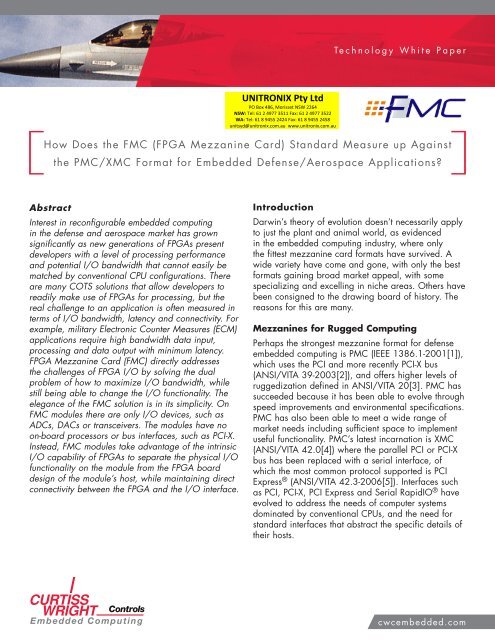
Abstract<br />
<strong>the</strong> PMC/XMC Format for Embedded Defense/Aerospace Applications?<br />
Interest in reconfigurable embedded computing<br />
in <strong>the</strong> defense and aerospace market has grown<br />
significantly as new generations of <strong>FPGA</strong>s present<br />
developers with a level of processing performance<br />
and potential I/O bandwidth that cannot easily be<br />
matched by conventional CPU configurations. There<br />
are many COTS solutions that allow developers to<br />
readily make use of <strong>FPGA</strong>s for processing, but <strong>the</strong><br />
real challenge to an application is often measured in<br />
terms of I/O bandwidth, latency and connectivity. For<br />
example, military Electronic Counter <strong>Measure</strong>s (ECM)<br />
applications require high bandwidth data input,<br />
processing and data output with minimum latency.<br />
<strong>FPGA</strong> <strong>Mezzanine</strong> <strong>Card</strong> (<strong>FMC</strong>) directly addresses<br />
<strong>the</strong> challenges of <strong>FPGA</strong> I/O by solving <strong>the</strong> dual<br />
problem of how to maximize I/O bandwidth, while<br />
still being able to change <strong>the</strong> I/O functionality. The<br />
elegance of <strong>the</strong> <strong>FMC</strong> solution is in its simplicity. On<br />
<strong>FMC</strong> modules <strong>the</strong>re are only I/O devices, such as<br />
ADCs, DACs or transceivers. The modules have no<br />
on-board processors or bus interfaces, such as PCI-X.<br />
Instead, <strong>FMC</strong> modules take advantage of <strong>the</strong> intrinsic<br />
I/O capability of <strong>FPGA</strong>s to separate <strong>the</strong> physical I/O<br />
functionality on <strong>the</strong> module from <strong>the</strong> <strong>FPGA</strong> board<br />
design of <strong>the</strong> module’s host, while maintaining direct<br />
connectivity between <strong>the</strong> <strong>FPGA</strong> and <strong>the</strong> I/O interface.<br />
Introduction<br />
Darwin’s <strong>the</strong>ory of evolution doesn’t necessarily apply<br />
to just <strong>the</strong> plant and animal world, as evidenced<br />
in <strong>the</strong> embedded computing industry, where only<br />
<strong>the</strong> fittest mezzanine card formats have survived. A<br />
wide variety have come and gone, with only <strong>the</strong> best<br />
formats gaining broad market appeal, with some<br />
specializing and excelling in niche areas. O<strong>the</strong>rs have<br />
been consigned to <strong>the</strong> drawing board of history. The<br />
reasons for this are many.<br />
<strong>Mezzanine</strong>s for Rugged Computing<br />
Perhaps <strong>the</strong> strongest mezzanine format for defense<br />
embedded computing is PMC (IEEE 1386.1-2001[1]),<br />
which uses <strong>the</strong> PCI and more recently PCI-X bus<br />
(ANSI/VITA 39-2003[2]), and offers higher levels of<br />
ruggedization defined in ANSI/VITA 20[3]. PMC has<br />
succeeded because it has been able to evolve through<br />
speed improvements and environmental specifications.<br />
PMC has also been able to meet a wide range of<br />
market needs including sufficient space to implement<br />
useful functionality. PMC’s latest incarnation is XMC<br />
(ANSI/VITA 42.0[4]) where <strong>the</strong> parallel PCI or PCI-X<br />
bus has been replaced with a serial interface, of<br />
which <strong>the</strong> most common protocol s<strong>up</strong>ported is PCI<br />
Express ® (ANSI/VITA 42.3-2006[5]). Interfaces such<br />
as PCI, PCI-X, PCI Express and Serial RapidIO ® have<br />
evolved to address <strong>the</strong> needs of computer systems<br />
dominated by conventional CPUs, and <strong>the</strong> need for<br />
standard interfaces that abstract <strong>the</strong> specific details of<br />
<strong>the</strong>ir hosts.<br />
cwcembedded.com
<strong>How</strong>ever, as <strong>the</strong> performance barriers are pushed<br />
back, some applications look toward <strong>FPGA</strong>s as<br />
<strong>the</strong> only practical way of achieving <strong>the</strong> necessary<br />
throughput, which could be beyond <strong>the</strong> capabilities of<br />
PMC or XMC. <strong>FPGA</strong>s can also be used to implement<br />
<strong>the</strong> necessary interfaces, so advantage can be made<br />
out of <strong>the</strong> direct co<strong>up</strong>ling of processing performance<br />
and I/O bandwidth. This applies very well to<br />
applications such as Electronic Counter <strong>Measure</strong>s<br />
(ECM), which can require latencies and bandwidth<br />
exceeding <strong>the</strong> <strong>the</strong>oretical capabilities of PCI Express<br />
(2Gbytes/sec using a x8 interface for PCI Express,<br />
Generation 1). PCI Express or PCI-X latency can be in<br />
<strong>the</strong> order of 1-2µS.<br />
<strong>FPGA</strong> <strong>Mezzanine</strong> <strong>Card</strong>s (<strong>FMC</strong>)<br />
<strong>FMC</strong> (ANSI/VITA 57.1-2008[6]) is aimed at solutions<br />
that require <strong>the</strong> benefits of an <strong>FPGA</strong>. This standard is<br />
showing a lot of promise in terms of longevity, as it<br />
does not compete with PMC/XMC – <strong>the</strong> recognized<br />
mezzanine leader for rugged computing – but ra<strong>the</strong>r<br />
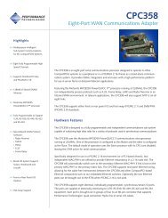
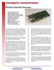
solves a problem for high-end applications (Figure<br />
1 shows a typical <strong>FMC</strong> module). In fact, <strong>the</strong> <strong>FMC</strong><br />
specification leverages some of <strong>the</strong> goodness of <strong>the</strong><br />
PMC and XMC specifications. The alternative for using<br />
<strong>FMC</strong> for high bandwidth, low latency data throughput<br />
is not to use mezzanines at all, but a monolithic PCB,<br />
a route that would lose <strong>the</strong> advantage of flexibility.<br />
Page 2<br />
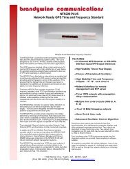
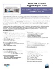
Figure 2: Summary of <strong>FMC</strong> connectivity<br />
Power S<strong>up</strong>ply<br />
Parallel or<br />
High-speed Serial I/O<br />
Device(s)<br />
Analog, Digital, Fiber,<br />
Video, <strong>FPGA</strong>/CPU,<br />
Memory, etc.<br />
Figure 1: Typical <strong>FMC</strong> Module (Curtiss-Wright<br />
<strong>FMC</strong>-516 ADC [8])<br />
<strong>Mezzanine</strong> cards for <strong>FPGA</strong>-based solutions are not<br />
new, but <strong>the</strong>y are invariably based on a proprietary<br />
standard which means users are locked into a<br />
particular vendor, and <strong>the</strong> evolution of <strong>the</strong> standard<br />
is not subject to peer review. The <strong>FMC</strong> standard<br />
has been ratified for three years now, so it is worth<br />
reviewing how successful <strong>the</strong> <strong>FMC</strong> specification has<br />
become. But first, it would be useful to review what<br />
<strong>the</strong> <strong>FMC</strong> specification entails. The general connectivity<br />
is outlined below in Figure 2 and includes a large<br />
number of parallel and serial connections directly to a<br />
host based <strong>FPGA</strong>.<br />
<strong>FMC</strong> (VITA 57) Connector<br />
Power (12V, 5V, Vadj),<br />
JTAG, I2C, Clocks<br />
High-speed Serial Connectivity<br />
Up to 10 MGT pairs<br />
Parallel Connectivity<br />
HPC: Up to 160/80 (SE/Diff pairs)<br />
or<br />
LPC: Up to 68/34 (SE/Diff pairs)<br />
Host <strong>FPGA</strong> Interface<br />
cwcembedded.com
The purpose of <strong>the</strong> <strong>FMC</strong> specification is to allow<br />
(usually) one <strong>FPGA</strong> on a host card to connect directly<br />
with <strong>the</strong> I/O devices on <strong>the</strong> mezzanine module – just<br />
as if <strong>the</strong> device were on <strong>the</strong> host board. Busses like<br />
PCI-X are redundant and would get in <strong>the</strong> way of <strong>the</strong><br />
<strong>FPGA</strong> and its I/O devices. This intimacy means <strong>the</strong><br />
interface can be optimal and savings can be made in<br />
real estate, cost and power, while boosting bandwidth<br />
and reducing latency.<br />
An <strong>FMC</strong> is similar in height and width to a PMC,<br />
but around half <strong>the</strong> length. The reduced width,<br />
compared with PMC or XMC, allows <strong>up</strong> to three<br />
<strong>FMC</strong>s to be fitted to a 6U host. The <strong>FMC</strong> specification<br />
has a default stacking height of 10mm, but permits<br />
a stacking height down to 8.5mm for low profile<br />
solutions.<br />
The majority of <strong>FMC</strong> host/carriers use 3U/6UVPX,<br />
VXS and AMC formats but <strong>the</strong>re are also PCI Express<br />
solutions such as <strong>the</strong> Xilinx ® ML605 Virtex ® -6<br />
evaluation card[7].<br />
The <strong>FMC</strong> specification provides for a large number<br />
of differential connections – <strong>up</strong> to 80 pairs or 160<br />
single-ended signals – to s<strong>up</strong>port high speed parallel<br />
interfaces between <strong>the</strong> <strong>FPGA</strong> and I/O devices. There<br />
are also a number of serial connections (<strong>up</strong> to ten<br />
pairs) suitable for Multi-Gigabit Transceivers (MGTs)<br />
operating <strong>up</strong> to 10Gb/s. <strong>FMC</strong> modules and hosts<br />
s<strong>up</strong>port two connector options; a Low Pin Count (LPC)<br />
160 pin connector or High Pin Count (HPC) 400 pin<br />
connector. The majority of <strong>FMC</strong> solutions are likely to<br />
use <strong>the</strong> HPC variant.<br />
Although aimed at I/O, <strong>FMC</strong> can be used for any<br />
function that might connect to an <strong>FPGA</strong> including<br />
DSPs, memory or even ano<strong>the</strong>r <strong>FPGA</strong>.<br />
Connectivity<br />
Connectivity for <strong>FMC</strong> modules is unusual in that only<br />
<strong>the</strong> <strong>up</strong>per limit of active connections is defined, as<br />
opposed to <strong>the</strong> number of active connections. This<br />
means that host carriers need not provide <strong>the</strong> same<br />
number of <strong>FPGA</strong> signals as ano<strong>the</strong>r host. This matters<br />
only in defining a given host’s ability to s<strong>up</strong>port<br />
certain <strong>FMC</strong> modules. To fully populate an HPC<br />
Page 3<br />
solution may require a large <strong>FPGA</strong>, so reduced pin-out<br />
offers cost sensitivity. This is something to be aware of,<br />
but <strong>the</strong> specification defines <strong>the</strong> signals to populate <strong>the</strong><br />
LPC or HPC connector starting at a given position and<br />
add to <strong>the</strong> connector in a given sequence, such that<br />
if two hosts provide x signals, <strong>the</strong>y will use <strong>the</strong> same<br />
connector pins and be compatible.<br />
Power S<strong>up</strong>ply<br />
For power s<strong>up</strong>ply requirements, <strong>the</strong> <strong>FMC</strong> specification<br />
employs a useful trick, at least for <strong>the</strong> <strong>FMC</strong>: <strong>the</strong><br />
host detects what <strong>the</strong> <strong>FMC</strong>’s power should be on its<br />
primary power rail and provides it. This is achieved<br />
through <strong>the</strong> host interrogating <strong>the</strong> <strong>FMC</strong>’s E2PROM,<br />
co<strong>up</strong>led with an adjustable power s<strong>up</strong>ply. The benefit<br />
to <strong>the</strong> <strong>FMC</strong> is a simplified power requirement, <strong>the</strong>reby<br />
freeing <strong>up</strong> valuable real estate for more I/O on <strong>the</strong><br />
<strong>FMC</strong>.<br />
Usable Printed Wafer Board (PWB) Real<br />
Estate<br />
Although occ<strong>up</strong>ying around half <strong>the</strong> PWB area of an<br />
XMC, <strong>the</strong> <strong>FMC</strong> can sometimes achieve greater I/O<br />
functionality, most notably for rugged applications.<br />
If <strong>the</strong> solution requires a large <strong>FPGA</strong> and if <strong>the</strong> XMC<br />
module complies with <strong>the</strong> VITA 20 specification, <strong>the</strong>re<br />
are restrictions as to where <strong>the</strong> <strong>FPGA</strong> can be located.<br />
In turn, this may limit <strong>the</strong> available area to fit <strong>the</strong> I/O<br />
devices. Consider an actual example with a pair of<br />
designs using <strong>the</strong> same I/O devices for a rugged<br />
application; one using an XMC format card and<br />
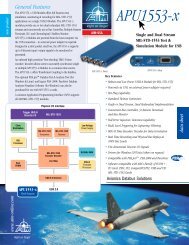
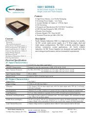
one using an <strong>FMC</strong> format card (Figure 3). Since <strong>the</strong><br />
rugged XMC specification requires an area across <strong>the</strong><br />
middle of <strong>the</strong> board to mate <strong>up</strong> with a host stiffening<br />
bar (which doubles as a primary <strong>the</strong>rmal interface<br />
on conduction-cooled variants), a large <strong>FPGA</strong> (for<br />
example 35x35mm) invariably needs to be fitted<br />
to <strong>the</strong> area of <strong>the</strong> circuit board closest to <strong>the</strong> front<br />
panel, just where <strong>the</strong> design would want to fit <strong>the</strong><br />
I/O devices. The useful space in which to fit <strong>the</strong> I/O<br />
devices is perhaps a quarter of <strong>the</strong> overall real estate<br />
of <strong>the</strong> XMC and not very efficient.<br />
In comparison, <strong>the</strong> <strong>FMC</strong>, though around half <strong>the</strong> size<br />
of <strong>the</strong> XMC, has a far greater real estate area for<br />
<strong>the</strong> I/O devices. In this example, <strong>the</strong> <strong>FMC</strong> is able to<br />
s<strong>up</strong>port two ADCs for two 3GS/s channels compared<br />
cwcembedded.com
to <strong>the</strong> single channel of <strong>the</strong> XMC. Of course an XMC<br />
using a smaller <strong>FPGA</strong>, or not restricted by <strong>the</strong> rugged<br />
XMC specification, may not be affected to such an<br />
extent, provided it still has a sufficient number of I/O<br />
connections to <strong>the</strong> devices. An <strong>FMC</strong> may be smaller,<br />
but it may still be able to s<strong>up</strong>port greater functionality<br />
than its larger XMC equivalent.<br />
Figure 3: Rugged XMC with large <strong>FPGA</strong> real estate<br />
example comparison with an <strong>FMC</strong><br />
Page 4<br />
Cooling<br />
Cooling rugged <strong>FPGA</strong>-based XMC cards can be<br />
a significant challenge as such boards can easily<br />
exceed 20W power dissipation. Typical rugged aircooled<br />
specifications for such cards define <strong>up</strong>per<br />
air-inlet temperatures of 70°C and conduction-cooled<br />
cold walls of 85°C. Making a mezzanine work within<br />
this environment with much lower power levels is<br />
already difficult. To compound this, XMC hosts often<br />
have two XMC sites. Consider <strong>the</strong> size and orientation<br />
of an XMC. When plugged onto a 3U host card,<br />
such as 3U VPX, <strong>the</strong> XMC covers <strong>the</strong> majority of<br />
host’s real estate which means, if <strong>the</strong>re are any hot<br />
devices on <strong>the</strong> host, <strong>the</strong>y are under <strong>the</strong> XMC. This is<br />
not ideal and can seriously affect cooling. The XMC<br />
mezzanine’s devices face down onto <strong>the</strong> host, not <strong>the</strong><br />
outside, placing <strong>the</strong> heat generating devices opposite<br />
those on <strong>the</strong> host and compound <strong>the</strong> cooling problem<br />
fur<strong>the</strong>r. To cool <strong>the</strong> XMC, <strong>the</strong> air needs to be squeezed<br />
between <strong>the</strong> host and mezzanine which can be a<br />
very small cross section, thus limiting <strong>the</strong> volume of air<br />
available to cool <strong>the</strong> assembly. Conduction cooling is<br />
less difficult but having all <strong>the</strong> heat generators in one<br />
plane is still a problem as <strong>the</strong>re may be hot spots.<br />
A 6U solution is not really any better; some of <strong>the</strong><br />
host’s real estate is not covered by mezzanines, but<br />
<strong>the</strong> <strong>the</strong>rmal paths to ei<strong>the</strong>r <strong>the</strong> cooling air inlet or cold<br />
wall interface are longer.<br />
Cooling is ano<strong>the</strong>r advantage for <strong>FMC</strong> based designs.<br />
An <strong>FMC</strong>, being smaller than an XMC, ensures that<br />
a larger amount of space on <strong>the</strong> host carrier is not<br />
covered by <strong>the</strong> mezzanine itself. Appropriate <strong>FMC</strong><br />
host design allows for suitable heat sinks to be<br />
implemented in <strong>the</strong> areas not restricted by mezzanine<br />
placement. S<strong>up</strong>erior cooling with ei<strong>the</strong>r greater airflow<br />
or greater heat sink cross sectional areas may<br />
be <strong>the</strong> factor that determines whe<strong>the</strong>r <strong>the</strong> solution is<br />
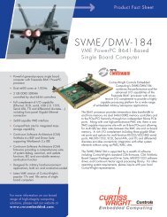
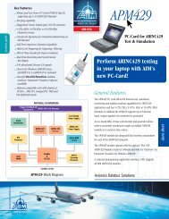
viable. In addition, as <strong>the</strong> <strong>FMC</strong> has no <strong>FPGA</strong>, only<br />
I/O devices, <strong>the</strong> <strong>FMC</strong> will be easier to cool as well –<br />
especially if <strong>the</strong> devices are not above a host’s <strong>the</strong>rmal<br />
hot spot (see Figure 4). The <strong>FMC</strong> specification limits<br />
<strong>the</strong> power dissipation of a single width module to<br />
10W.<br />
cwcembedded.com
Figure 4: 6U VPX <strong>FMC</strong> host with two <strong>FMC</strong> sites (and<br />
4x <strong>FPGA</strong>s)<br />
Key Benefits of <strong>FMC</strong> Compared to PMC/<br />
XMC<br />
Latency<br />
In determining which applications best suit an <strong>FMC</strong><br />
approach, <strong>the</strong> decision really hinges on whe<strong>the</strong>r <strong>the</strong>re<br />
is a benefit from using an <strong>FPGA</strong>. Latency is very low<br />
for <strong>FMC</strong>s. If an <strong>FMC</strong> s<strong>up</strong>ports both input and output,<br />
<strong>the</strong>n a solution can be realized in which one or more<br />
analog signals are digitized and read directly and<br />
processed by an <strong>FPGA</strong>, with <strong>the</strong> data <strong>the</strong>n transmitted<br />
back out through <strong>the</strong> same <strong>FMC</strong>. In this case no<br />
busses, not even between <strong>FPGA</strong>s, are required. The<br />
only delay is <strong>the</strong> <strong>FPGA</strong> processing which can be<br />
as low as a few nanoseconds. This type of solution<br />
is ideal for an application like Electronic Counter<br />
<strong>Measure</strong>s (ECM) and Electronic S<strong>up</strong>port <strong>Measure</strong>s<br />
(ESM) where processing response time is critical.<br />
Page 5<br />
Bandwidth<br />
XMCs might get around <strong>the</strong> bandwidth problem,<br />
compared with <strong>FMC</strong>s, through decimation or using<br />
newer generation serial interfaces operating at ever<br />
higher speeds. <strong>How</strong>ever, some applications may<br />
not be able to tolerate this reduction in data off <strong>the</strong><br />
mezzanine. Beam-forming applications may fall<br />
into this category where high bandwidth data, from<br />
potentially a large number of channels, must be<br />
shared between processing elements. Therefore, high<br />
bandwidth beam-forming is ano<strong>the</strong>r good application<br />
area for <strong>FMC</strong> technology because it would not suffer<br />
from data reduction problems.<br />
Simplicity<br />
<strong>FMC</strong>s by nature promise a faster development<br />
turnaround cycle, through lower complexity and<br />
a focus on <strong>the</strong> I/O itself within <strong>the</strong> design. This<br />
makes <strong>FMC</strong>s a good choice for system <strong>up</strong>grades<br />
as newer, faster and high resolution devices come<br />
onto <strong>the</strong> market. This is an advantage for Software<br />
Defined Radio (SDR) applications. There is a great<br />
deal of flexibility afforded by implementing different<br />
modulation and coding schemes which can be<br />
performed in a common <strong>FPGA</strong> host. Additional<br />
flexibility results from being able to <strong>up</strong>grade to new<br />
higher resolution ADCs as <strong>the</strong>y become available,<br />
without <strong>the</strong> need to develop complex interface<br />
structures and new power s<strong>up</strong>plies. <strong>FMC</strong>s and <strong>FPGA</strong><br />
processing make an ideal platform for a wide range<br />
of digital receivers.<br />
Flexibility<br />
RADAR has a thirst for increasing resolution and<br />
bandwidths, and benefits from direct RF digitization<br />
for coherent sampling. Lower bandwidth solutions<br />
require IF stages and I/Q sampling which introduces<br />
noise. <strong>FMC</strong> provides <strong>the</strong> easiest format to <strong>up</strong>grade<br />
<strong>the</strong> platform as new faster ADCs become available.<br />
Direct sampling of <strong>up</strong> to X-band frequencies, with<br />
appropriate digitizers, means that applications such<br />
as marine, ATC, wea<strong>the</strong>r and surveillance RADAR are<br />
well within <strong>the</strong> capabilities of <strong>FMC</strong> bandwidth. Faster<br />
ADCs are continually being developed so <strong>up</strong>grading<br />
is quick and easy.<br />
cwcembedded.com
Customization<br />
If <strong>the</strong> appropriate <strong>FMC</strong> function does not exist, it is<br />
now easier for customers to design <strong>the</strong>ir own cards<br />
to fit on a third party <strong>FMC</strong> host and more easily track<br />
new technology, such as higher resolution ADCs as<br />
<strong>the</strong>y become available. The conceptual simplicity of<br />
<strong>FMC</strong> makes this approach more viable and reduces<br />
system risk.<br />
See Figure 5 for example applications mapping onto<br />
different latency and bandwidth requirements.<br />
Limitations<br />
Finite Connectivity<br />
No mezzanine specification is perfect because its<br />
target markets are usually varied, and <strong>the</strong>refore a<br />
compromise. If <strong>the</strong> compromises are few, <strong>the</strong>n <strong>the</strong>se<br />
imperfections can be overlooked. S<strong>up</strong>porting <strong>up</strong> to 80<br />
differential signals, it is easy to conceive of parallel<br />
interfaces providing data throughputs in excess of<br />
10GB/s and largely limited only by <strong>the</strong> host <strong>FPGA</strong>’s<br />
capabilities. <strong>How</strong>ever, although 80 differential<br />
signals represent significant connectivity, it is finite.<br />
A monolithic design, not using a mezzanine, could<br />
provide more than 80 <strong>FPGA</strong> pairs to connect to <strong>the</strong><br />
devices on <strong>the</strong> <strong>FMC</strong>. The practicality of <strong>FMC</strong>s is down<br />
to <strong>the</strong> host <strong>FPGA</strong> and I/O devices. An example is a<br />
3.6GS/s 12bit ADC, which exists today and might<br />
use 1:4 multiplexer to allow it to be interfaced to an<br />
<strong>FPGA</strong>. Such a device would require 48 LVDS pairs,<br />
probably clocked at 450MHz DDR. This would use<br />
more than half of <strong>the</strong> <strong>FMC</strong>’s connectivity for parallel<br />
connections for <strong>the</strong> data path alone, on top of which<br />
control signals would be needed. In this example only<br />
a single ADC device could be implemented on an<br />
<strong>FMC</strong> even though <strong>the</strong>re may be sufficient space and<br />
power budget to fit on a second part. <strong>How</strong>ever, by<br />
comparison, <strong>the</strong> performance bandwidth for <strong>FMC</strong>s<br />
over XMCs is considerable.<br />
Page 6<br />
Front Panel I/O<br />
<strong>FMC</strong> is a front panel only format, unlike XMC and<br />
PMC which define user I/O signals that might be<br />
routed to a backplane for convenience. <strong>How</strong>ever, this<br />
is rarely used for analog signals where noise might<br />
be introduced through such routing. Mechanically,<br />
<strong>the</strong> <strong>FMC</strong> front panel width is slightly narrower than its<br />
XMC counterpart, leaving less room for connectors.<br />
<strong>FPGA</strong> Centric<br />
By its very definition, <strong>FMC</strong> requires an <strong>FPGA</strong>. This<br />
means <strong>the</strong> <strong>FMC</strong> will never achieve <strong>the</strong> universal<br />
appeal of PMC or XMC, but for applications that<br />
require such levels of performance as provided by an<br />
<strong>FPGA</strong>, this is of minor consideration. Today, <strong>the</strong>re are<br />
relative few <strong>FMC</strong>s and <strong>FMC</strong> host carriers, where PMC<br />
and XMC have built <strong>up</strong> an extensive portfolio number<br />
in <strong>the</strong> 100s or even 1000s with proven track records.<br />
Cross-Vendor Compatibility<br />
By definition, software and HDL for <strong>FMC</strong>s is defined<br />
by <strong>the</strong> host. And because <strong>the</strong> <strong>FMC</strong> is controlled by<br />
an <strong>FPGA</strong>, <strong>the</strong>re is no real concept of a driver. So<br />
although <strong>FMC</strong>s from different 3 rd parties will fit toge<strong>the</strong>r<br />
electronically and mechanically, <strong>the</strong>re will be differences<br />
in <strong>the</strong> host’s environment leading to incompatibility.<br />
<strong>How</strong>ever, within <strong>the</strong> <strong>FPGA</strong> world, electrical and<br />
mechanical compatibility are of primary performance.<br />
HDL is often user specific and often not an issue.<br />
<strong>FMC</strong> Market Traction<br />
The <strong>FMC</strong> format is gaining momentum. There are<br />
already more than fifteen vendors providing <strong>FMC</strong><br />
modules, host or complete combinations. The majority<br />
of <strong>FMC</strong> solutions on <strong>the</strong> market today are high speed<br />
analog input or output with good coverage of channel<br />
density, resolution and ruggedization levels. This is not<br />
surprising because this is an area that requires raw<br />
bandwidth and <strong>FPGA</strong> processing. In addition, <strong>the</strong>re<br />
are now approaching a hundred products covering<br />
functionality such as tuners, digital I/O, fiber-optics,<br />
10GE<strong>the</strong>rnet and even <strong>FPGA</strong> co-processors. There<br />
is even product s<strong>up</strong>porting system busses such as<br />
1553. Analog input products include solutions <strong>up</strong> to<br />
250MS/s 16-bit for high resolution, and 5GS/s (10b)<br />
for high speed capability.<br />
cwcembedded.com
© Copyright 2011, Curtiss-Wright Controls<br />
All Rights Reserved. MKT-WP-<strong>FMC</strong>-052611v1<br />
Summary<br />
The choice of which mezzanine format is best<br />
for rugged embedded computing solutions will<br />
ultimately be down to issues such as application<br />
details, perception of risk, development timeline and<br />
personal preference. The baseline for choosing which<br />
mezzanine is most suitable for certain applications is<br />
how it compares with a monolithic board (i.e. a single<br />
PWB with all functionality onboard). A monolithic card<br />
usually provides <strong>the</strong> best technical solution because it<br />
does not have <strong>the</strong> restrictions imposed by segmenting<br />
<strong>the</strong> design, such as number of connector I/O pins to<br />
<strong>the</strong> mezzanine.<br />
While not absolute, Table 1 below provides a first<br />
cut assessment as to which technology scores best<br />
against different parameters. <strong>How</strong>ever, differences in<br />
<strong>the</strong> requirement from one application to ano<strong>the</strong>r may<br />
affect <strong>the</strong>se conclusions.<br />
Table 1: Relative comparison of mezzanine<br />
capabilities<br />
PMC XMC <strong>FMC</strong> Monolithic<br />
Bandwidth a aa aaa aaa<br />
Latency a a aaa aaa<br />
Installed base of<br />
users<br />
Time to design new<br />
board<br />
Power dissipation,<br />
ease of cooling<br />
Note: (aaa best)<br />
Page 7<br />
aaa aa a aa<br />
aa aa aaa a<br />
a a aa aaa<br />
Figure 5: <strong>How</strong> typical applications map onto<br />
bandwidth and latency requirements<br />
<strong>FMC</strong> Continues to Evolve<br />
Although <strong>FMC</strong> is now a published standard, <strong>the</strong>re are<br />
some parallel specifications in development within <strong>the</strong><br />
VME Industrial Trade Association (VITA). These deal with<br />
abstractions to simplify integration into systems such as<br />
<strong>FPGA</strong> driver concepts. When ready, <strong>the</strong>se additional<br />
standards will streng<strong>the</strong>n some of <strong>the</strong> perceived weakness<br />
with <strong>FMC</strong>. <strong>FMC</strong> is ready now as an electro-mechanical<br />
solution that will serve a wide range of applications now.<br />
Conclusion<br />
<strong>FMC</strong>s promise to do for <strong>FPGA</strong> based solutions what PMC<br />
and XMC did for embedded CPU based systems. <strong>How</strong>ever,<br />
<strong>FMC</strong> is not really competing with PMC or XMC, but actually<br />
complements it, particularly for high bandwidth, low latency<br />
applications.<br />
References<br />
[1] IEEE 1386.1-2001 <strong>Standard</strong> Physical and Environmental Layers for PCI<br />
<strong>Mezzanine</strong> <strong>Card</strong>s<br />
[2] ANSI/VITA 39-2003: American National <strong>Standard</strong> for PCI-X Auxiliary<br />
<strong>Standard</strong> for PMCs and Processor PMCs.<br />
[3] ANSI/VITA 20 (R2005): American National <strong>Standard</strong> for Conduction<br />
Cooled PMC<br />
[4] ANSI/VITA 42.0-2008: STANDARD FOR VITA 42.0 XMC<br />
[5] ANSI/VITA 42.3-2006: American National <strong>Standard</strong> for XMC PCI<br />
Express Protocol Layer <strong>Standard</strong><br />
[6] ANSI/VITA 57.1:-2008: American National <strong>Standard</strong> for <strong>FPGA</strong><br />
<strong>Mezzanine</strong> <strong>Card</strong> (<strong>FMC</strong>) <strong>Standard</strong><br />
[7] Xilinx ML605 Virtex-6 evaluation card: www.xilinx.com<br />
[8] Curtiss-Wright Controls Embedded Computing web site<br />
www.cwcembedded.com<br />
All o<strong>the</strong>r brands and names are property of <strong>the</strong>ir respective owners.<br />
cwcembedded.com