Conduit Bending Basics (Iron - Klein Tools
Conduit Bending Basics (Iron - Klein Tools
Conduit Bending Basics (Iron - Klein Tools

Create successful ePaper yourself
Turn your PDF publications into a flip-book with our unique Google optimized e-Paper software.
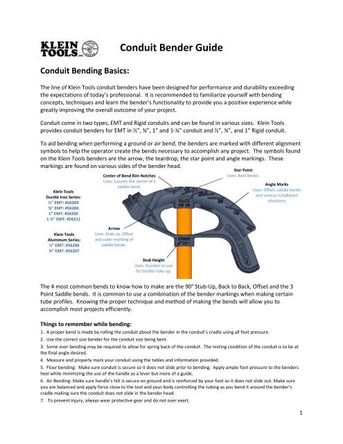
<strong>Conduit</strong> <strong>Bending</strong> <strong>Basics</strong>:<br />
Arrow<br />
Uses: Stub-up, Offset<br />
and outer marking of<br />
saddle bends.<br />
<strong>Conduit</strong> Bender Guide<br />
The line of <strong>Klein</strong> <strong>Tools</strong> conduit benders have been designed for performance and durability exceeding<br />
the expectations of today’s professional. It is recommended to familiarize yourself with bending<br />
concepts, techniques and learn the bender’s functionality to provide you a positive experience while<br />
greatly improving the overall outcome of your project.<br />
<strong>Conduit</strong> come in two types, EMT and Rigid conduits and can be found in various sizes. <strong>Klein</strong> <strong>Tools</strong><br />
provides conduit benders for EMT in ½”, ¾”, 1” and 1-¼” conduit and ½”, ¾”, and 1” Rigid conduit.<br />
To aid bending when performing a ground or air bend, the benders are marked with different alignment<br />
symbols to help the operator create the bends necessary to accomplish any project. The symbols found<br />
on the <strong>Klein</strong> <strong>Tools</strong> benders are the arrow, the teardrop, the star point and angle markings. These<br />
markings are found on various sides of the bender head.<br />
<strong>Klein</strong> <strong>Tools</strong><br />
Ductile <strong>Iron</strong> Series:<br />
½” EMT: #56203<br />
¾” EMT: #56204<br />
1” EMT: #56205<br />
1-¼” EMT: #56211<br />
<strong>Klein</strong> <strong>Tools</strong><br />
Aluminum Series:<br />
½” EMT: #56206<br />
¾” EMT: #56207<br />
Center of Bend Rim Notches<br />
Uses: Locates the center of a<br />
saddle bend.<br />
Stub Height<br />
Uses: Number to use<br />
for bender take-up.<br />
Star Point<br />
Uses: Back bends.<br />
Angle Marks<br />
Uses: Offset, saddle bends<br />
and various installation<br />
situations<br />
The 4 most common bends to know how to make are the 90° Stub-Up, Back to Back, Offset and the 3<br />
Point Saddle bends. It is common to use a combination of the bender markings when making certain<br />
tube profiles. Knowing the proper technique and method of making the bends will allow you to<br />
accomplish most projects efficiently.<br />
Things to remember while bending:<br />
1. A proper bend is made by rolling the conduit about the bender in the conduit’s cradle using all foot pressure.<br />
2. Use the correct size bender for the conduit size being bent.<br />
3. Some over bending may be required to allow for spring back of the conduit. The resting condition of the conduit is to be at<br />
the final angle desired.<br />
4. Measure and properly mark your conduit using the tables and information provided.<br />
5. Floor bending: Make sure conduit is secure so it does not slide prior to bending. Apply ample foot pressure to the benders<br />
heel while minimizing the use of the handle as a lever but more of a guide.<br />
6. Air <strong>Bending</strong>: Make sure handle’s hilt is secure on ground and is reinforced by your foot so it does not slide out. Make sure<br />
you are balanced and apply force close to the tool and your body controlling the tubing as you bend it around the bender’s<br />
cradle making sure the conduit does not slide in the bender head.<br />
7. To prevent injury, always wear protective gear and do not over exert.<br />
1
90° Stub-Up Bend:<br />
The stub bend is made by bending a piece of conduit into an L shape or 90° bend by placing the free end<br />
(short end) of the tube to a predetermined length as indicated in the diagram below. This is the most<br />
common bend and is a building block for other bends. Common uses for this bend are: Running conduit<br />
into electrical boxes, running conduit up or down walls, running conduit into walls through floors and<br />
ceilings and making inner and outer corner turns.<br />
Bender Take Up Table<br />
90° Stub-Up Bend<br />
<strong>Conduit</strong><br />
Size<br />
Stub<br />
Height<br />
Amount to subtract<br />
from Measurement<br />
½” EMT 5”<br />
¾” EMT 6”<br />
and ½” Rigid<br />
1” EMT 8”<br />
and ¾” Rigid<br />
1-¼” EMT 11”<br />
and 1” Rigid<br />
1. Determine the overall free end height of the conduit you want after the bend.<br />
2. From the overall free height, subtract the stub height listed in the Bender Take-Up Table for the<br />
conduit size you are bending. <strong>Klein</strong> <strong>Tools</strong> has provided the correct stub height on each bender head.<br />
3. On the conduit, measure from the free end to be bent up the calculated number and mark the<br />
conduit.<br />
As an example, to bend 3/4” EMT conduit have a free end height<br />
of 8.5”, the table indicates to subtract 6” from the 8.5” which<br />
leave 2.5” from the end to bend up to make the mark. Tip:<br />
Advanced benders can lay a tape measure next to the conduit and perform the<br />
bending operations if the bend does not call for high degree of accuracy.<br />
4. Always use the proper size conduit bender for the conduit size being<br />
bent. The conduit will not bend properly and/or will be damaged if a<br />
mismatch of bender and conduit size is used. Place the bender onto the<br />
tubing with the hook pointed towards the free end to be bent upwards.<br />
Make sure the conduit is resting properly in the bender’s hook and<br />
lineup the arrow symbol with the mark you placed on the tubing.<br />
2
5. Keeping the conduit flat, apply ample foot pressure to the bender’s heel minimizing the use of<br />
the handle as a lever, rolling up the free end into the 90° position checking the degree with a<br />
level. When done properly the free end will be at the desired height and the arrow will be at<br />
the stub height as indicated.<br />
In some installations there will be a need to cut down the<br />
unbent side of the conduit to another desired length to fit<br />
the installation. Use a tube cutter for smooth precise<br />
cutting and burr removal to ensure the safety of the<br />
electrical wiring when pulled through. A hacksaw can be<br />
substituted as long as the tubing’s cut edge is prepared<br />
properly.<br />
<strong>Klein</strong> <strong>Tools</strong> Tube Cutter: #88975 & 88977<br />
<strong>Klein</strong> <strong>Tools</strong> Hacksaw: #701-10, 701 -12 &701 -S<br />
<strong>Klein</strong> <strong>Tools</strong> Level: #931-6RE & 931-7RE<br />
3
Back to Back Bends:<br />
The back to back bend is the next style of bend that is needed while running electrical conduit. In reality<br />
the concept is formulated by the need to know the distance from the back edge of a 90° bend to a fixed<br />
point down the conduit to mark for other bend operations to meet the installation requirement. As you<br />
will see it builds on the 90° stub bend and when done the most common use of this bend will look like<br />
an elongated U.<br />
You will need to know this bend method when you want to fit conduit between two parallel surfaces<br />
such as two walls or joists while keeping the U’s outer edges of the legs touching the two surfaces. This<br />
allows for proper anchoring and a nice clean appearance.<br />
2. The first bend for the back to back bend is the 90°<br />
stub-up bend. Follow the steps from the 90° Stub-<br />
Up section to create the ideal bend for the<br />
connection on the first side.<br />
3. From the back edge of the 90° stub-up bend,<br />
measure the distance found in step 1 and make<br />
your mark on the conduit.<br />
1. Determine the distance between<br />
the two parallel surfaces to get the<br />
dimension for back to back bend.<br />
4. Place the bender on the conduit with the bender’s hook facing the free end of the tube to be<br />
bent opposite the original bend side. Make sure the conduit is resting properly in the bender’s<br />
cradle and lineup the Star Point Symbol with the mark you placed on the tubing.<br />
4
5. Keeping the conduit flat, apply ample foot pressure to the bender’s heel, with minimal use of<br />
the handle as a lever, rolling up the free end into the 90° position checking the degree with a<br />
level. It is very important to keep the first 90° bend in the same plane as the new bend. If not<br />
the two legs of the U will be skewed and will not produce the desired shape. If this happens,<br />
some correcting can be done to properly align the legs depending on how out of shape they are.<br />
When the bend is done properly the conduit will lay flat and will fit inside the two surfaces<br />
measured.<br />
In some installations there will be a need to cut down the unbent side of the conduit to another desired length to fit the installation. Use a tube<br />
cutter for smooth precise cutting and burr removal to ensure the safety of the electrical wiring when pulled through. A hacksaw can be<br />
substituted as long as the tubing’s cut edge is prepared properly.<br />
<strong>Klein</strong> <strong>Tools</strong> Tube Cutter: #88975 & 88977<br />
<strong>Klein</strong> <strong>Tools</strong> Hacksaw: #701-10, 701 -12 &701 -S<br />
<strong>Klein</strong> <strong>Tools</strong> Level: #931-6RE & 931-7RE<br />
If the back to back distance is short (a tight U) so the bender has problems fitting to make the<br />
second bend, you may compensate by subtracting the stub height from the measured distance to fit<br />
the gap then follow step 3 to mark the calculated number on the conduit. But this time you would<br />
put the bender on the conduit with the hook facing the first bend and line up the Arrow Symbol as<br />
demonstrated in the Stub-Up section, step 5, with the conduit mark and proceed to make the bend<br />
as in step 5 rolling up the previously bent end up into the 90° position giving you the desired<br />
dimension. Caution should be taken when creating the second bend. With this technique the first bend will be coming at<br />
the operator as the second bend is made.<br />
5
Offset Bends:<br />
An offset bend is a style of bend that is built independently of the 90° stub and the Back to Back<br />
bend and is an important bend to know when running conduit. It is common to shift the conduit a<br />
certain distance while continuing to run parallel in the same direction as the pre-shift portion of the<br />
conduit. There are many situations that call for an offset bend. The most common uses of this bend<br />
are: staggered joists, running tight on a wall and offset into an electrical box and changes in<br />
elevation.<br />
Offset Formula Table<br />
Angle of Constant Shrink Per<br />
Bend Multiplier Inch of Offset<br />
10° X 10° 6 1/16 = .063<br />
22½° X<br />
22½°<br />
2.6 3/16 = .188<br />
30° X 30° 2.0 1/4 = .250<br />
45° X 45° 1.4 3/8 = .375<br />
60° X 60° 1.2 1/2 = .500<br />
1. Determine/measure the offset distance necessary to clear the obstacle and how far away the<br />
offset will need to be bent from the end of the conduit.<br />
2. Decide what angle you wish to make the offset bend and determine the proper values from the<br />
Offset Formula Table. Calculate the proper values to mark on the conduit to clear the obstacle<br />
and fit in the gap measured.<br />
Offset Formula Table<br />
Angle of Constant Shrink Per<br />
Bend Multiplier Inch of Offset<br />
45° X 45° 1.4 3/8 = .375<br />
As an example, the offset distance of the obstacle is 6” and<br />
the distance to obstacle is 20”. The installation allows for<br />
a 45° X 45° offset bend. Note: The choice of degree is<br />
usually the installer’s choice and most of the time the<br />
installation location will determine what degree will fit.<br />
6
3. From the table use the 45° X 45° offset row for the values to calculate the series of markings<br />
necessary to make the proper bend. To find out where to place the first mark on the conduit,<br />
multiply the measured Offset Distance to clear the obstacle by the tables Shrink/Inch that will<br />
occur to the conduit after all the bends are made due to that offset distance or:<br />
(Offset Distance) X (Shrink/Inch) = Total Shrink.<br />
Example: 6” X .375 = 2.25” of total shrink.<br />
This value is then added to the measured Distance to Obstacle number or:<br />
(Distance to Obstacle) + (Total Shrink) = First Mark Distance.<br />
Example: 20” + 2.25” = 22.25” to make first mark.<br />
To calculate the second mark needed on the conduit, multiply the measured Offset Distance by<br />
the Constant Multiplier of the table or:<br />
(Offset Distance) X (Constant Multiplier) = Second Mark Distance (Distance between Marks).<br />
Example: 6” X 1.4 = 8.4” between 1 st & 2 nd mark.<br />
This calculated value is how far apart to make your marks from each other on the conduit and<br />
where to make your 45° bends.<br />
4. Using the technique to align the<br />
bender on the conduit as<br />
described under the Stub-Up<br />
Section 5, Place the bender on<br />
the conduit with the hook<br />
facing away from the second<br />
mark and line up the Arrow<br />
Symbol up with the first mark.<br />
7
6. Keeping the bender and conduit together flip the<br />
two parts upside down and put the bender’s handle<br />
hilt on the floor, balancing the conduit in the air,<br />
allow the conduit to rotate 180° in the cradle. Slide<br />
the conduit down so the first bend is moving away<br />
from the bender head, aligning the second mark as<br />
outlined before using the Arrow Symbols (See Stub-<br />
Up section, note 5).<br />
5. Keeping the conduit flat, apply ample foot<br />
pressure to the bender’s heel minimizing the use<br />
of the handle as a lever, smoothly rolling up the<br />
free end until the 45° mark is reached. When<br />
done properly the free end will be at a 45° angle<br />
from the original plane.<br />
Note: Some over bending may be required to allow for<br />
spring back of the conduit. The resting condition of the<br />
conduit is to be at the final angle desired.<br />
7. The second bend of the offset is<br />
accomplished by performing an air-bend. Make<br />
sure the handle hilt is secure on ground and is<br />
reinforced by your foot so it does not slide out.<br />
Make sure you are balanced and apply force close<br />
to the tool and your body controlling the tubing as<br />
you bend it around the bender’s cradle. Bend the<br />
free end until the 45° mark is reached.<br />
It is very important to keep the first 45° bend in the same plane as the new bend will be. If not, the two<br />
legs of the offset will be skewed and will not produce the desired shape. If this happens, some<br />
correcting can be done to properly align the legs depending on how out of shape they are. When the<br />
bend is done properly the conduit will lay flat and fit inside the measured distance to and clear the<br />
obstacle.<br />
In some installations there will be a need to cut down<br />
the unbent side of the conduit to another desired<br />
length to fit the installation. Use a tube cutter for<br />
smooth precise cutting and burr removal to ensure the<br />
safety of the electrical wiring when pulled through. A<br />
hacksaw can be substituted as long as the tubing’s cut<br />
edge is prepared properly.<br />
<strong>Klein</strong> <strong>Tools</strong> Tube Cutter: #88975 & 88977<br />
<strong>Klein</strong> <strong>Tools</strong> Hacksaw: #701-10, 701 -12 &701 -S<br />
8
Three Point Saddle Bend:<br />
The three point saddle bend is a variant of the offset bend since it is an offset bend that returns to the<br />
original in-line run after clearing an obstacle. This bend is intended to bridge over obstacles such as<br />
existing conduit or plumbing running perpendicular to the intended conduit installation.<br />
1. Determine/measure the offset distance necessary to clear the obstacle and how far away the<br />
saddle bend will need to be from the edge of the conduit. Unlike the offset bend you must<br />
measure to the center of the obstacle to bridge over.<br />
2. Choose the angle that will be used for the center bend. The other two return bends will be 1/2<br />
the center angle chosen. If the center angle is 45°, the two return bends will be 22.5°. Use the<br />
table to calculate the distance between bends and how much shrink is to occur to the conduit<br />
due to the bends.<br />
Degree of<br />
Bend:<br />
3 Point Saddle Bend Table<br />
45° Center<br />
Bend<br />
60° Center<br />
Bend<br />
22.5° Return Bends<br />
Obstruction Shrink Distance off<br />
Height Amount Center Mark<br />
Every inch Add: 3/16” 2-1/2” 1/4” 2”<br />
1” 3/16” 2-1/2” 1/4” 2”<br />
2” 3/8” 5” 1/2” 4”<br />
3” 9/16” 7-1/2” 3/4” 6”<br />
4” 3/4” 10” 1” 8”<br />
5” 15/16” 12-1/2” 1-1/4” 10”<br />
6” 1-1/8” 15” 1-1/2” 12”<br />
30° Return Bends<br />
Shrink Distance off<br />
Amount Center Mark<br />
Example: As an example, the offset<br />
distance of an obstacle is 2” and the<br />
distance to obstacle’s center point is 20”.<br />
The installation allows for a 45° saddle<br />
bend. Note: The choice of degree is usually<br />
the installer’s choice and most of the time<br />
the installation location will determine what<br />
degree will fit.<br />
3. Calculate the value needed to place your first mark on the conduit. This number is determined<br />
by the Measured Distance to Center Point of the obstacle plus the Shrink from the 3 Point<br />
Saddle Bend Table that will occur.<br />
(Measured Distance to Center Point) + (Shrink) = Center Mark<br />
Example: 20” + 3/8” = 20-3/8”<br />
9
4. Using the Distance off Center Mark values found in the table to clear a 2” obstacle, simply mark<br />
that distance from the center line in both directions or subtract this number from the center<br />
mark value for the first return bend mark and add that number to the center mark value to<br />
obtain the second return bend mark distance.<br />
5. Mark the conduit accordingly.<br />
6. Place the bender on the conduit and<br />
position the appropriate Center of<br />
Bend Rim Notch on the center mark in<br />
the orientation shown.<br />
(Center Mark) – (Distance off Center Mark) = 1 st Return Bend Mark<br />
Example: (20-3/8”) – 5” = 15-3/8”<br />
(Center Mark) + (Distance off Center Mark) = 2 nd Return Bend Mark<br />
60°<br />
Example: (20-3/8”) + 5” = 25-3/8”<br />
45°<br />
30°<br />
10
7. Keeping the conduit flat, apply ample foot<br />
pressure to the bender’s heel minimizing the<br />
use of the handle as a lever, smoothly rolling<br />
up the free end until the 45° mark is reached.<br />
Note: Some over bending may be required to allow for spring<br />
back of the conduit. The resting condition of the conduit is to<br />
be at the final angle desired.<br />
8. Keeping the bender and conduit together, flip<br />
the two parts upside down and put the bender’s<br />
handle hilt on the floor, balancing the conduit in the<br />
air, allow the conduit to rotate 180° in the cradle.<br />
Slide the conduit down so the first bend is moving<br />
away from the bender head, aligning the 1 st return<br />
bend mark with the Arrow Symbol (See Stub-Up<br />
section, note 5).<br />
Note: Some over bending may be required to allow for spring back of the conduit. The resting condition of the<br />
conduit is to be at the final angle desired.<br />
9. The second bend of the saddle bend is<br />
accomplished by performing an air-bend.<br />
Make sure handle hilt is secure on ground<br />
and is reinforced by your foot so it does<br />
not slide out. Make sure you are<br />
balanced and apply force close to the tool<br />
and your body controlling the tubing as<br />
you bend it around the bender’s cradle.<br />
Bend the free end until the 22.5° mark is<br />
reached.<br />
11
11. The last bend of the saddle bend<br />
is made again by performing an airbend.<br />
Make sure handle hilt is secure<br />
on ground and is reinforced by your foot<br />
so it does not slide out. Make sure you<br />
are balanced and apply force close to<br />
the tool and your body controlling the<br />
tubing as you bend it around the<br />
bender’s cradle. Bend the free end until<br />
the 22.5° mark is reached.<br />
10. Remove bender and place it back on the<br />
conduit on the other side of the center bend with the<br />
hook facing the center bend as before aligning Arrow<br />
Symbol (See Stub-Up section, note 5). On the 2 nd<br />
return bend mark.<br />
Note: Some over bending may be required to allow for spring back<br />
of the conduit. The resting condition of the conduit is to be at the<br />
final angle desired<br />
It is very important to keep all the bends in the same plane. If not, the offset will be skewed and will<br />
not produce the desired shape. If this happens some correcting can be done to properly align the legs<br />
depending on how out of shape they are. When the bend is done properly the conduit will lay flat and<br />
will fit the measured distance to obstacle, clear the object and return to the original line continuing the<br />
run as desired.<br />
In some installations there will be a need to cut down the unbent side of the conduit to another desired length to fit the installation. Use a tube<br />
cutter for smooth precise cutting and burr removal to ensure the safety of the electrical wiring when pulled through. A hacksaw can be<br />
substituted as long as the tubing’s cut edge is prepared properly.<br />
<strong>Klein</strong> <strong>Tools</strong> Tube Cutter: #88975 & 88977<br />
<strong>Klein</strong> <strong>Tools</strong> Hacksaw: #701-10, 701 -12 &701 -S<br />
12