HILT 9000 Handheld Inductive Loop Tester - Athens Technical ...
HILT 9000 Handheld Inductive Loop Tester - Athens Technical ...
HILT 9000 Handheld Inductive Loop Tester - Athens Technical ...

Create successful ePaper yourself
Turn your PDF publications into a flip-book with our unique Google optimized e-Paper software.
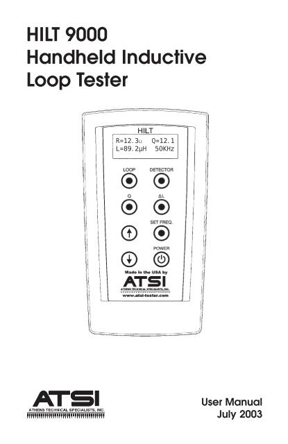
<strong>HILT</strong> <strong>9000</strong><br />
<strong>Handheld</strong> <strong>Inductive</strong><br />
<strong>Loop</strong> <strong>Tester</strong><br />
R=12.3Ω Q=12.1<br />
L=89.2µH 50KHz<br />
User Manual<br />
July 2003
<strong>HILT</strong> <strong>9000</strong> - <strong>Inductive</strong> <strong>Loop</strong> <strong>Tester</strong><br />
Table of Contents<br />
Receiving Your Shipment......................................................... 2<br />
Packaging................................................................................ 2<br />
Description ............................................................................. 3<br />
Overview of <strong>HILT</strong> <strong>9000</strong> Controls .............................................. 5<br />
Function Controls ................................................................... 5<br />
Power ................................................................................ 5<br />
<strong>Loop</strong> .................................................................................. 5<br />
Q ................................................................................................................ 6<br />
Set Frequency, Arrows ....................................................... 7<br />
∆L ...................................................................................... 7<br />
Detector............................................................................. 8<br />
Function Controls Summary ................................................... 9<br />
Overview of Traffic <strong>Loop</strong> Detection Systems ............................ 9<br />
Battery Replacement ............................................................. 11<br />
Commonly Asked Questions.................................................. 12<br />
Repair and Calibration .......................................................... 13<br />
<strong>Technical</strong> and Sales Assistance ............................................. 14<br />
Limited Warranty .................................................................. 16<br />
Warranty Repair .................................................................... 16<br />
1
2 www.atsi-tester.com<br />
Warnings<br />
These safety warning are provided to ensure the safety of<br />
personnel and proper operation of the tester.<br />
• The tester must not be operated beyond its specified<br />
operating range.<br />
• Safety is the responsibility of the operator.<br />
Receiving your Shipment<br />
Upon receiving your shipment, be sure that the contents are<br />
consistent with the packing list. Notify your distributor or factory<br />
of any missing items. If the equipment appears to be damaged,<br />
file a claim immediately with the carrier and notify your the<br />
factory at once, giving a detailed description of any damage.<br />
Save the damaged packing container to substantiate your claim.<br />
Packaging<br />
The <strong>HILT</strong> <strong>9000</strong> <strong>Inductive</strong> <strong>Loop</strong> <strong>Tester</strong> is shipped with a hard<br />
carrying case, one set of test leads with clips, two 9V batteries<br />
(installed), and a user manual. Depending on whether you<br />
purchased the <strong>HILT</strong> <strong>9000</strong> only or the complete <strong>Loop</strong> Test Kit, you<br />
may have additional items included.
<strong>HILT</strong> <strong>9000</strong> - <strong>Inductive</strong> <strong>Loop</strong> <strong>Tester</strong><br />
General Description<br />
The <strong>HILT</strong>-<strong>9000</strong> is designed to measure characteristics of an<br />
inductive loop at different frequencies; measure working<br />
parameters of the loop system; as well as simulate the detector<br />
by measuring the change of inductance. The measurement<br />
modes can be easily switched by pressing corresponding buttons<br />
on the keypad.<br />
The following tests can be run to verify the condition of the loop:<br />
Where,<br />
• R, L, and Q of the loop<br />
• Operating parameters of the loop system: operating mode,<br />
frequency (f OP ), and peak-to-peak voltage (V PP )<br />
• Change of inductance of the loop (∆L/L)<br />
Q = quality factor (dimensionless)<br />
L = inductance (µH)<br />
R DC = DC resistance (Ω)<br />
f OP = operating frequency (KHz)<br />
V PP = peak-to-peak voltage (V)<br />
The tester offers a user-selectable frequency at which Q and L<br />
are measured. At power-up, the frequency is pre-set to 50KHz<br />
and can be easily changed from 20KHz to 80KHz range using the<br />
keypad.<br />
An inductance change (∆L/L) can be measured to assess the real<br />
life behavior of the loop. In this mode the tester displays the<br />
current value of the inductance change and the maximum<br />
observed change which can be reset by pressing a button on the<br />
keypad.<br />
When the loop is connected to a detector, the tester can measure<br />
the oscillating frequency and peak-to-peak voltage of the signal.<br />
In addition, the tester detects the operating mode and indicates if<br />
it is a continuous (single channel) or scanning (for most multichannel<br />
detectors).<br />
The tester has a 16 by 2-character LCD for presenting the<br />
measured values to the user. The control keypad has 7 command<br />
buttons and one Power On/Off button. The tester requires two<br />
standard 9V alkaline batteries. To extend the life of the batteries,<br />
the tester shuts off automatically after 30 seconds of non-use.<br />
3
4 www.atsi-tester.com<br />
Overview of <strong>HILT</strong> <strong>9000</strong> Controls<br />
1. LOOP: Measures R DC , L, and<br />
Q. If Q>15, use Q pushbutton<br />
to obtain actual value.<br />
2. Q: Measures high Q values<br />
(when Q is >15).<br />
3. Used in SET FREQ mode to<br />
increase frequency by 1KHz.<br />
4. Used in SET FREQ mode to<br />
decrease frequency by 1KHz.<br />
5. POWER: Turns unit On/Off.<br />
Ready: 100%<br />
Select Function<br />
Figure 1<br />
6. SET FREQ: Selects operating<br />
frequency to measure L & Q.<br />
7. ∆L: Measures change of<br />
inductance.<br />
8. DETECTOR: Measures<br />
operating parameters of the<br />
loop system: V P-P , Oscillating<br />
frequency, and mode.<br />
9. Input: Color coded input<br />
connectors.
<strong>HILT</strong> <strong>9000</strong> - <strong>Inductive</strong> <strong>Loop</strong> <strong>Tester</strong><br />
Function Controls<br />
Power<br />
Press the POWER push-button to turn the tester on and off. The<br />
tester performs an initial self-test to verify that the internal<br />
circuit is working. After the self-test is complete, the tester shows<br />
the current battery level and the message: Ready: Select<br />
Function. If the battery is low, a message Replace Battery will<br />
be displayed.<br />
Press and hold the POWER push-button during power-up to<br />
display the serial number of the unit and the version of the<br />
firmware as show in Figure 2. Release<br />
the push-button to return to normal<br />
operation.<br />
The unit can be turned off at any time<br />
by pressing the POWER button. The<br />
tester shuts off automatically after 30<br />
seconds of non-use.<br />
<strong>Loop</strong><br />
ATTENTION<br />
<strong>HILT</strong>-<strong>9000</strong> #1234<br />
Self-test v.1.0<br />
Figure 2<br />
• Disconnect the detector from the loop before running<br />
this test.<br />
• DO NOT switch to a different test while the measurements<br />
are being generated for the current test. Only<br />
after the results of the current test are displayed can<br />
a different test be performed.<br />
Connect the test leads to the loop. Press the LOOP push-button<br />
to begin the test. After the measurement is complete, the tester<br />
displays the results as shown in Figure 3 on the next page. Note<br />
that the frequency at which L and Q were measured is also<br />
displayed.<br />
5
6 www.atsi-tester.com<br />
The LOOP test can measure a maximum<br />
Q of 15. If Q is greater than 15<br />
the tester displays Q>15. To measure<br />
the actual value, press the Q button on<br />
the keypad to run a separate Q test.<br />
The default frequency at which the<br />
LOOP and Q tests run is 50 KHz. It can<br />
be changed to any value within the<br />
range from 20 KHz to 80 KHz with 1<br />
KHz increment.<br />
Quality (Q)<br />
ATTENTION<br />
• Disconnect the detector from the loop before running<br />
this test.<br />
• DO NOT switch to a different test while the measurements<br />
are being generated for the current test. Only<br />
after the results of the current test are displayed can<br />
a different test be performed.<br />
Connect the test leads to the loop. This test requires several<br />
seconds to run during which the tester will measure Q at<br />
some arbitrary frequency and calculate Q for a user-selected<br />
frequency. If a user-selected frequency is not entered prior to<br />
pressing Q, the default 50KHz setting<br />
will be used. Refer to the Set<br />
Frequency section on page 7 for<br />
full instructions to enter a different<br />
frequency.<br />
Both Q results will be presented on the<br />
display as shown in Figure 4. The<br />
calculated value is shown on the<br />
second line and indicated with an *.<br />
R=12.3Ω Q=12.1<br />
L=89.2µH 50KHz<br />
Figure 3<br />
Q=12.1 @40.5KHz<br />
* Q=14.9 @50.0KHz<br />
Figure 4
<strong>HILT</strong> <strong>9000</strong> - <strong>Inductive</strong> <strong>Loop</strong> <strong>Tester</strong><br />
, , Set Frequency<br />
When the tester is powered, the test frequency is automatically<br />
set to 50 KHz. The frequency can be changed to any value<br />
between 20 KHz and 80 KHz with 1 KHz resolution. To set a<br />
different frequency press the SET<br />
FREQ push-button to view the frequency<br />
adjustment display as show in<br />
Figure 5. Use the or push-button to<br />
increase or decrease the frequency by<br />
1KHz. Pressing and holding or <br />
button will automatically increase/<br />
decrease the value.<br />
Change of Inductance<br />
ATTENTION<br />
• Disconnect the detector from the loop before running<br />
this test.<br />
• Prior to measuring the operating parameters of the loop<br />
system, press the DETECTOR push-button and verify<br />
the tester displays the “No Signal” message. Once this<br />
message is received the detector can be reconnected to<br />
the loop.<br />
In this mode, the tester simulates a detector by measuring a<br />
relative change of the inductance and displaying the results.<br />
Connect the test leads to the loop and<br />
press ∆L button on the keypad. The<br />
display will appear as shown in Figure<br />
6. The top line indicates the current<br />
change of the inductance and the<br />
bottom line indicates the maximum<br />
recorded change of inductance. To<br />
reset the maximum value press the ∆L<br />
button.<br />
Test @ frequency<br />
F=50 KHz<br />
Figure 5<br />
dL/L= 0.127%<br />
max= 3.378%<br />
Figure 6<br />
7
8 www.atsi-tester.com<br />
If there is bad connection, the tester<br />
displays a message as shown in Figure<br />
7. Make sure that the test leads are<br />
properly connected. If the leads are<br />
connected to the loop and the message<br />
is still present, it means that Q of the<br />
loop is too low to generate the oscillation<br />
or the inductance is out of range.<br />
This can be verified by performing the<br />
LOOP test.<br />
In this mode, the the tester will shut off automatically after 45<br />
seconds if no buttons are pressed.<br />
Detector<br />
ATTENTION<br />
• Verify the <strong>Loop</strong> is connected to detection system before<br />
running this test.<br />
• Disconnect the detector from the loop before running a<br />
LOOP, Q, or ∆L test.<br />
The purpose of this test is to measure<br />
the operating parameters of the<br />
working loop while it is connected to<br />
the detector.<br />
Connect the test leads to the loop and<br />
press the DETECTOR push-button.<br />
During this test the measurements are<br />
constantly updated displaying the type<br />
of the operating mode, peak-to-peak<br />
voltage, and the operating frequency as<br />
show in Figure 8. If the signal is not<br />
present or signal is weak, the tester<br />
displays “No Signal” message as show<br />
in Figure 9.<br />
In this mode, the the tester will shut<br />
off automatically after 45 seconds if no<br />
buttons are pressed.<br />
dL/L:<br />
No loop found<br />
Figure 7<br />
Scan. mode:<br />
7.4V @F=34.1KHz<br />
Figure 8<br />
No signal<br />
-.-V @F=--.-KHz<br />
Figure 9
<strong>HILT</strong> <strong>9000</strong> - <strong>Inductive</strong> <strong>Loop</strong> <strong>Tester</strong><br />
Function Controls Summary<br />
BUTTON DESCRIPTION COMMENTS<br />
LOOP Used to measure L, Q, and R DC<br />
of the loop. Q is measured up<br />
to 15. If Q>15, use Q button to<br />
obtain the actual value of Q<br />
Q Used to measure high Q<br />
values (when Q is >15)<br />
∆L Used to measure change of<br />
inductance<br />
DETECTOR Used to measure operating<br />
parameters of the loop<br />
system: V P-P , Oscillating<br />
Frequency, and Mode<br />
SET FREQ. Used to select operating<br />
frequency to measure L and Q<br />
and Used in SET FREQ mode to<br />
increase and decrease<br />
frequency in 1KHz steps.<br />
POWER Used to turn the unit on and<br />
off.<br />
The loop must be<br />
disconnected from the<br />
system to run this test<br />
The loop must be<br />
disconnected from the<br />
system to run this test<br />
The loop must be<br />
disconnected from the<br />
system to run this test<br />
The loop must be<br />
connected from the<br />
system to run this test<br />
The tester can be<br />
turned off at any time<br />
during or after a test<br />
9
10 www.atsi-tester.com<br />
Overview of Traffic <strong>Loop</strong> Detection Systems<br />
The inductive loop represents the most commonly used method<br />
to detect vehicles. The inductive loop is simply a coil of wires<br />
embedded into the pavement and can be characterized by several<br />
parameters, L (inductance), Q (quality factor), R (active resistance,<br />
measured using AC signal), and R DC (DC resistance).<br />
These parameters are affected by the type of pavement, number<br />
of turns in the loop, type of wire, length and type of the lead-in<br />
cable, shape and dimension of the loop, and presence of any<br />
objects near the loop.<br />
A detector is connected to the loop and is used to measure the<br />
AC characteristics of the loop and change of those. A part of the<br />
circuitry in the detector and the loop creates an oscillating<br />
circuit. The oscillating frequency of this circuit depends on the<br />
parameters of the loop and the parameters of the detector. When<br />
a vehicle or other metallic mass is located above the loop almost<br />
all of the characteristics (except DC resistance R DC ) are altered.<br />
This change causes the oscillating frequency to drift which in<br />
turn is detected by the detector.<br />
Unfortunately, the deterioration of the loop begins virtually from<br />
the moment of installation. There appear to be two basic mechanisms<br />
for loop degradation, mechanical and chemical. Under<br />
daily and seasonal temperature variations, the pavement is<br />
constantly flexing. To this may be added the pounding of heavy<br />
vehicles, particularly at the approaches to signalized intersections<br />
where loops are often located. These mechanical factors<br />
cause flexure of the wires comprising the loop, especially at the<br />
juncture between pavement and berm, leading initially to fine<br />
cracks in the insulation, and perhaps ultimately to actual<br />
breakage of the wires. After insulation failure occurs (fine cracks<br />
or breakage), there is a path for water intrusion. While water<br />
itself is a poor conductor, its conductivity is greatly increased by<br />
the highly ionic de-icing salts which saturate the berm and all<br />
cracks and fissures of the pavement. Aside from the ground<br />
leakage which results, these highly active solutions can actually<br />
erode the copper conductors by displacement, aided by electrolysis<br />
of even the small potentials of the wire to ground. Lead-in<br />
wires are also vulnerable, especially on long pulls through<br />
conduit, because of the high probability of minor insulation<br />
failures due to chafing and stretching during installation.
<strong>HILT</strong> <strong>9000</strong> - <strong>Inductive</strong> <strong>Loop</strong> <strong>Tester</strong><br />
To guarantee a reliable oscillation in the loop system the quality<br />
factor (Q) of the loop with the lead-in wires should be above some<br />
value, determined by the amplifiers inside the detector. Deterioration<br />
of the loop and lead-in wires reduces Q and eventually<br />
prevents the system from oscillating even with a known good<br />
detector.<br />
Battery replacement<br />
NEVER OPEN THE BATTERY COMPARTMENT<br />
WHILE THE <strong>HILT</strong>-<strong>9000</strong> POWER IS ON.<br />
The battery indicator (in percentage format) on the LCD indicates<br />
when the batteries in the <strong>HILT</strong>-<strong>9000</strong> require replacement. There<br />
are two 9V alkaline batteries in the <strong>HILT</strong>. Recommended replacement<br />
type is Alkaline (IEC 6LF22, 6LR61 or NEDA 1604A).<br />
To replace the batteries, you will need to open the battery cover<br />
on the backside of the tester. Lay the tester face-down on a flat<br />
table, making sure that there is nothing underneath the tester<br />
that can accidentally turn the tester on. Remove the two Phillips<br />
head screws that secure the battery cover. The battery cover can<br />
then be removed and access to the batteries obtained. Installation<br />
is the reverse of this procedure.<br />
All other types of services needed for the <strong>HILT</strong>-<strong>9000</strong> should only<br />
be performed by an ATSI factory technician. Any attempt at<br />
servicing the tester yourself or by someone other than a ATSI<br />
technician will void the factory warranty. See the Warranty<br />
statement at the end of this manual for full details.<br />
11
12 www.atsi-tester.com<br />
Commonly Asked Questions<br />
Q. Why do I have to disconnect the detector from the loop before<br />
running a <strong>Loop</strong>, Q, or ∆∆∆∆∆L test?<br />
A. During <strong>Loop</strong>, Q, and ∆L test, the tester is applying its own<br />
signal to the loop. The tester verifies there is no signal on the<br />
loop before running these tests. However, with a scanning<br />
detector connected to the loop, there are time intervals during<br />
which the loop does not have a signal applied. If the verification<br />
occurs during that time interval, the <strong>HILT</strong> will not “see” that<br />
there is another source of voltage connected to the loop and will<br />
begin the actual test. Presence of another voltage on the loop will<br />
result with incorrect measurements or potentially damage the<br />
tester.<br />
Q. When I run a Q test, why are there two results shown?<br />
A. The quality factor Q depends not only on the parameters of<br />
the loop but also the frequency of the measuring signal. During<br />
a Q test, the tester measures Q at a natural resonant frequency,<br />
which depends not only on the parameters of the loop but also<br />
those of the tester and it will not be the same as the userselected<br />
frequency. The Q measurement for the natural resonant<br />
frequency is displayed on the first line. The Q for the userselected<br />
frequency is calculated and is displayed on the second<br />
line.<br />
Q. Is an adapter available to plug into the detector rack that will<br />
allow testing from the detector’s connection points?<br />
A. Yes. Call your distributor or the factory for pricing and<br />
availability.
<strong>HILT</strong> <strong>9000</strong> - <strong>Inductive</strong> <strong>Loop</strong> <strong>Tester</strong><br />
Repair and Calibration<br />
To ensure that your instrument meets factory specifications, we<br />
recommend that it be returned to our factory at one-year<br />
intervals for calibration service. In addition to calibration of the<br />
test parameters, this service includes replacement of batteries<br />
and firmware updates. Please contact the factory for price and<br />
scheduling information on this service.<br />
Request a Return Merchandise Form by phone or by fax from<br />
our Service Department (or complete the form on our website at<br />
www.atsi-tester.com), then return the tester along with the<br />
completed RM Form. Return the tester, postage or shipment<br />
pre-paid to:<br />
ATSI<br />
8157 US Route 50 • <strong>Athens</strong>, OH 45701<br />
(740) 592-2874<br />
(740) 594-2875 - Fax<br />
service@atsi-tester.com<br />
Caution: To protect yourself against in-transit loss, we recommend<br />
you insure your returned materials.<br />
The <strong>HILT</strong>-<strong>9000</strong> is sold with a one-year limited warranty to the<br />
original purchaser, as defined by the limited warranty on the<br />
inside back cover of this manual. No other warranties, expressed<br />
or implied, apply to the <strong>HILT</strong>-<strong>9000</strong> or associated components.<br />
After the first year, ATSI will continue to provide repairs to the<br />
tester on a parts-plus-labor basis. A phone call describing the<br />
problem may allow ATSI to make a nonbinding estimate of repair<br />
costs, but the surest approach is to send back the tester for a<br />
comprehensive evaluation and a binding repair estimate.<br />
13
14 www.atsi-tester.com<br />
<strong>Technical</strong> and Sales Assistance<br />
If you are experiencing any technical problems, or require any<br />
assistance with the proper operation or application of your<br />
tester, please call, fax, or e-mail our technical support staff:<br />
ATSI<br />
8157 US Route 50 • <strong>Athens</strong>, OH 45701<br />
(740) 592-2984<br />
(740) 594-2875 - Fax<br />
service@atsi-tester.com<br />
NOTES
<strong>HILT</strong> <strong>9000</strong> - <strong>Inductive</strong> <strong>Loop</strong> <strong>Tester</strong><br />
-- This page left blank --<br />
15
16 www.atsi-tester.com<br />
Limited Warranty<br />
The <strong>HILT</strong> <strong>9000</strong> (“Product”), distributed by <strong>Athens</strong> <strong>Technical</strong> Specialists, Inc.<br />
(ATSI), is warranted to the original purchaser (“Purchaser”) to be free of<br />
defects in materials and workmanship for a period of one year from the<br />
purchase date stated on the invoice. Within this period, in the event of a<br />
defect, malfunction, or other failure of the product while in the custody of<br />
the purchaser, ATSI will remedy the defect or cause of failure without<br />
charge to the Purchaser. Purchaser’s sole remedy is restoration of product<br />
operation. ATSI accepts no liability for incidental or related expenses. Under<br />
no circumstances will ATSI’s liability exceed the purchase price for items<br />
claimed to be defective.<br />
This Limited Warranty does not extend to any Product that has been<br />
damaged or rendered defective (a) as a result of accident, misuse, or abuse:<br />
(b) by modification of the product: or (3) as a result of service by anyone<br />
other than ATSI.<br />
EXCEPT AS EXPRESSLY SET FORTH IN THIS WARRANTY, ATSI MAKES NO<br />
OTHER WARRANTIES, EXPRESS OR IMPLIED, INCLUDING ANY IMPLIED<br />
WARRANTIES OF MERCHANTABILITY AND FITNESS FOR A PARTICULAR<br />
PURPOSE. ATSI EXPRESSLY DISCLAIMS ALL WARRANTIES NOT STATED<br />
IN THIS LIMITED WARRANTY.ANY IMPLIED WARRANTIES THAT MAY BE<br />
IMPOSED BY LAW ARE LIMITED TO THE TERMS OF THIS EXPRESS<br />
LIMITED WARRANTY.<br />
YOU CAN NOW REGISTER ONLINE AT:<br />
www.atsi-tester.com<br />
Warranty Repair<br />
What you must do to return the tester for Warranty Repair:<br />
Request a Return Merchandise Form by phone or by fax from our Service<br />
Department (or complete the form on our website at www.atsi-tester.com),<br />
then return the tester along with the completed RM Form. Return the<br />
tester, postage or shipment pre-paid to:<br />
ATSI<br />
8157 US Route 50<br />
<strong>Athens</strong>, OH 45701<br />
(740) 592-2874<br />
(740) 594-2875 - Fax<br />
service@atsi-tester.com<br />
Caution: To protect yourself against in-transit loss, we recommend you<br />
insure your returned materials.