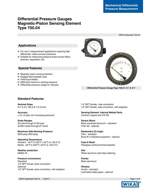
Differential Pressure Gauges Magnetic-Piston Sensing Element ...
Differential Pressure Gauges Magnetic-Piston Sensing Element ...
Differential Pressure Gauges Magnetic-Piston Sensing Element ...

Create successful ePaper yourself
Turn your PDF publications into a flip-book with our unique Google optimized e-Paper software.
<strong>Differential</strong> <strong>Pressure</strong> <strong>Gauges</strong><br />
<strong>Magnetic</strong>-<strong>Piston</strong> <strong>Sensing</strong> <strong>Element</strong><br />
Type 700.04<br />
Applications<br />
For use in measurement applications requiring high<br />
differential / static process pressures.<br />
Suitable for measuring pressure drops across filters,<br />
strainers, separators, etc.<br />
Special Features<br />
<strong>Magnetic</strong> piston sensing element<br />
Rugged thermoplastic case<br />
Field liquid fillable<br />
6000 psid maximum working pressure<br />
<strong>Differential</strong> pressure ranges to 100 psid<br />
Standard Features<br />
Mechanical <strong>Differential</strong><br />
<strong>Pressure</strong> Measurement<br />
WIKA Datasheet 700.04<br />
<strong>Differential</strong> <strong>Pressure</strong> Gauge Type 700.04 2½” & 4½”<br />
Nominal Sizes 1/4” NPT female, side connection<br />
2½” & 4½” (63.5 & 114.3 mm) 1/2” NPT female, side connection, with adapters<br />
Accuracy <strong>Sensing</strong> <strong>Element</strong>, Internal Wetted Parts<br />
± 2% of span (on increasing pressure) Ceramic magnet and 316 SS<br />
Scale Ranges Sensor Block<br />
0/5 psid through 0/100 psid Black anodized aluminum - standard<br />
(0/350 mbard through 0/7 bard) 316L SS - optional<br />
Maximum Safe Working <strong>Pressure</strong> Elastomers (O-rings)<br />
6000 psig (400 barg) Viton - standard<br />
Buna N or Ethylene propylene - optional<br />
Operating Temperature<br />
Ambient: -40°F to 200°F (-40°C to +93.3°C) Case & Bezel<br />
Media: -40°F to 200°F (-40°C to +93.3°C) Fiberglass reinforced thermoplastic<br />
Weather protection Dial<br />
NEMA 4X White aluminum with black lettering<br />
<strong>Pressure</strong> connections Pointer<br />
Standard: Black aluminum<br />
1/4” NPT female, back connection<br />
Optional: Window<br />
1/2” NPT female, back connection, with adapters Acrylic - standard<br />
Laminated safety glass - optional<br />
WIKA Datasheet 700.04 · 12/2011 Page 1 of 6<br />
R
Dial Case filling Order Options (min. order may apply)<br />
Glycerine - (changes to Model 703.04) Bidirectional reading<br />
Silicone - 1000 CST (changes to Model 703.04) Red drag pointer<br />
(no other case fills approved) Special connections<br />
Wall or pipe mounting kit<br />
Warranty Other pressure scales<br />
Seven (7) years limited Alarm contact switches<br />
Optional Wall Mounting/Pipe Mounting Bracket<br />
P/N 50994353<br />
Wall Mounting Configuration 1 Pipe Mounting Configuration<br />
Optional side connection shown<br />
Wall Mount/Pipe Mount Dimensions<br />
Size<br />
A B C<br />
2½” mm 71.1 203.2 70<br />
in 2.80 8.0 2.76<br />
Standard back connection shown<br />
Notes:<br />
1) Order optional end connections if standard back connections interfere with wall, or order standoff blocks to space from wall, as<br />
application requires.<br />
Wall & Pipe Mounting:<br />
The 700.04 can be configured with either a back mount sensor housing or a side mount sensor housing. The installation of the<br />
sensor housings must be done at the factory, as they are not field modification items.<br />
2.5” and 4.5” gauges<br />
Wall mount<br />
Rear connections will pose a problem for wall mounting unless the bracket & gauge assembly is held off of the wall in some<br />
fashion. A ½” aluminum standoff block is available to alleviate this problem. Customers can add the number of blocks required to<br />
adjust the installation to their particular application. Optional side connections will not experience this problem and will not require<br />
the standoff blocks.<br />
Pipe mount<br />
Like the wall mount application, the rear connections will pose a problem for pipe mounting unless the bracket & gauge assembly<br />
is held off of the pipe in some fashion. A stainless steel offset plate is is available to alleviate this problem. The plate is U-bolted to<br />
the pipe and after the gauge and bracket assembly is bolted to the plate, the plate will hold the gauge away from the pipe so that<br />
any connection can be applied. Optional side connections will not experience this problem and will not require the offset bracket.<br />
Page 2 of 6 WIKA Datasheet 700.04 · 12/2011
Optional Mounting Accessories<br />
Standoff Block<br />
part number: 50027611<br />
Used to hold wall mounting bracket away from the wall<br />
in order to access the rear gauge connections.<br />
Pipe Mounting Offset Plate<br />
part number: 50027620<br />
Used to hold pipe mounting bracket away from pipe in<br />
order to access rear gauge connections.<br />
WIKA Datasheet 700.04 · 12/2011 Page 3 of 6
Size<br />
øA C D E F G H K L M N S<br />
2½” mm 76 23.5 83.2 12.8 109 56.7 5.7 1.2 25.4 41.9 54 3.2<br />
in 2.99 0.92 3.28 0.50 4.29 2.23 0.22 0.05 1.0 1.65 2.13 0.13<br />
Size<br />
øA C D E G K L M N S<br />
4½” mm 132.4 28.8 157.7 37.3 62 25.7 25.4 45.1 54 2.9<br />
in 5.21 1.13 6.21 1.47 2.44 1.01 1.00 1.77 2.13 0.12<br />
P = PANEL CUTOUT<br />
B = BOLT CIRCLE<br />
Panel Cut-out Dimensions<br />
Size<br />
B J P<br />
2½” mm 89.6 4.7 76.8<br />
in 3.53 0.185 3.02<br />
4½” mm 143.4 4.7 133.4<br />
5.64 0.185 5.25<br />
Page 4 of 6 WIKA Datasheet 700.04 · 12/2011
Notes: Panel Mounting<br />
2.5”<br />
Surface mount<br />
The 2.5” gauge cannot be surface mounted in a panel due to the size of the sensor housing.<br />
Rear mount<br />
Must be a dry gauge with no drag pointer in order to rear mount in a panel. Do not loosen the screws of a filled<br />
gauge or leakage will result.<br />
Remove bezel screws (dry gauge) to relax any deformation of the bezel and insert the bezel into the panel cutout.<br />
Connect the gauge case to the bezel again from the rear and secure with the original screws inserted from the front<br />
of the panel, screwing into the case behind the panel.<br />
4.5”<br />
Surface mount<br />
Surface mounting can be done with either dry gauges or filled gauges.<br />
The 700.04 is provided with mounting studs for panel mounting in the surface-mount configuration. After making<br />
the proper cutout, install the studs in the rear of the gauge, install the gauge from the front of the panel and secure<br />
with the nuts provided with the gauge.<br />
Rear mount<br />
Must be a dry gauge with no drag pointer in order to rear mount in a panel. Do not loosen the screws of a filled<br />
gauge or leakage will result.<br />
Remove bezel screws (dry gauge) to relax any deformation of the bezel and insert the bezel into the panel cutout.<br />
Connect the gauge case to the bezel again from the rear and secure with the original screws inserted from the front<br />
of the panel, screwing into the case behind the panel.<br />
700.04 Weights<br />
Aluminum Dry Filled<br />
2.5” 0.6345 lbs. 0.7090 lbs.<br />
4.5” 1.6275 lbs. 2.0260 lbs.<br />
Stainless Dry Filled<br />
2.5” 1.3630 lbs. 1.4545 lbs.<br />
4.5” 1.6765 lbs. 2.0265 lbs.<br />
WIKA Datasheet 700.04 · 12/2011 Page 5 of 6
Operating and Installation Instructions<br />
Gauge Inspection: Gauge Mounting:<br />
Please read the product specifications label attached to the The 700.04 Series gauge is supplied, standard, for panel<br />
gauge body to insure that this gauge is the same one specified mounting. When installing the 2.5” dial gauge into the panel,<br />
for the particular application as it applies to dial size, materials remove the four (4) bezel screws, mount the gauge from back<br />
of construction, working pressure, differential pressure, etc. to front through the panel, then reinstall the four (4) bezel<br />
Inspect for any shipping damage and, if discovered, report it screws through the panel and into the bezel, securing the<br />
immediately. gauge to the panel. When installing the 4.5” dial gauge, install<br />
the four (4) threaded studs into the back of the dial case,<br />
Product Design Features: mount the gauge from front to back through the panel and<br />
The WIKA Type 700.04 Series is a magnetically coupled dif- secure the gauge to the back of the panel by tightening the<br />
ferential pressure gauge. The internal piston/magnet assem- locking nuts to the threaded studs. Optional pipe mount kits or<br />
bly travels linearly in a very close tolerance bore. A second wall mount kits (see back) are available. (Note: 2 1/2” gauge<br />
magnet attached to the pointer, tracks this movement. Thus cannot be panel mounted if case is liquid filled.)<br />
the pointer indicates the differential pressure on the dial. By<br />
design, there is a small flow-by of media within the sensor Gauge Connections:<br />
body, across the piston/magnet from side to side. The flow-by Supplied, standard, with (2) x ¼” FNPT back connections and<br />
rate across the piston will not exceed 25 SCFH of air at 100 are clearly indicated with Hi (+) and Lo (-). Optional connec-<br />
PSID at ambient conditions. Due to this design, both sides tion sizes and/or end connections are available.<br />
must see continuous flow to indicate differential pressure.<br />
IMPORTANT: The 700.04 series is not suitable for static pres- Troubleshooting:<br />
sure applications (i.e. level measurement) and cannot be used If the gauge is not indicating differential pressure, check to<br />
with diaphragm seals. insure that both the high (+) and low (-) connections have<br />
been properly installed. Check to insure that there is pressure<br />
to the high (+) side of the gauge and that there is differential<br />
pressure across the device being monitored by the<br />
Type 700.04 Series. If the gauge is being used together with a<br />
Measuring system diagram three-valve manifold, check to insure that the high (+) and low<br />
(-) valves are in the open position and the equalizer valve is in<br />
the closed position.<br />
Range<br />
Spring<br />
Rotary<br />
Magnet<br />
<strong>Piston</strong><br />
Magnet<br />
0<br />
1<br />
Low High<br />
2<br />
3<br />
4<br />
Switch<br />
Pointer<br />
Note: For more information about the optional Reed Switches, please refer to WIKA’s Switch Addendum.<br />
Ordering information<br />
<strong>Pressure</strong> gauge model / Nominal size / Scale range / Size of connection / Optional extras required Specifications and dimensions given in this leaflet represent the state of engineering at the<br />
time of printing. Modifications may take place and materials specified may be replaced by others without prior notice.<br />
Page 6 of 6 WIKA Datasheet 700.04 · 12/2011<br />
WIKA Instrument Corporation<br />
1000 Wiegand Boulevard<br />
Lawrenceville, GA 30043-5868<br />
Tel: 888-WIKA-USA • 770-513-8200<br />
Fax: 770-338-5118<br />
E-Mail: info@wika.com<br />
www.wika.com<br />
R