Spillway Gates Rehabilitation 1169 USACE EMSWORTH DAM ...
Spillway Gates Rehabilitation 1169 USACE EMSWORTH DAM ...
Spillway Gates Rehabilitation 1169 USACE EMSWORTH DAM ...

Create successful ePaper yourself
Turn your PDF publications into a flip-book with our unique Google optimized e-Paper software.
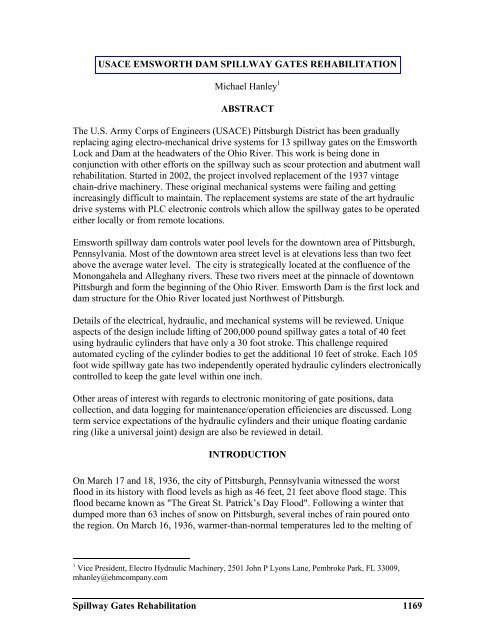
<strong>USACE</strong> <strong>EMSWORTH</strong> <strong>DAM</strong> SPILLWAY GATES REHABILITATION<br />
Michael Hanley 1<br />
ABSTRACT<br />
The U.S. Army Corps of Engineers (<strong>USACE</strong>) Pittsburgh District has been gradually<br />
replacing aging electro-mechanical drive systems for 13 spillway gates on the Emsworth<br />
Lock and Dam at the headwaters of the Ohio River. This work is being done in<br />
conjunction with other efforts on the spillway such as scour protection and abutment wall<br />
rehabilitation. Started in 2002, the project involved replacement of the 1937 vintage<br />
chain-drive machinery. These original mechanical systems were failing and getting<br />
increasingly difficult to maintain. The replacement systems are state of the art hydraulic<br />
drive systems with PLC electronic controls which allow the spillway gates to be operated<br />
either locally or from remote locations.<br />
Emsworth spillway dam controls water pool levels for the downtown area of Pittsburgh,<br />
Pennsylvania. Most of the downtown area street level is at elevations less than two feet<br />
above the average water level. The city is strategically located at the confluence of the<br />
Monongahela and Alleghany rivers. These two rivers meet at the pinnacle of downtown<br />
Pittsburgh and form the beginning of the Ohio River. Emsworth Dam is the first lock and<br />
dam structure for the Ohio River located just Northwest of Pittsburgh.<br />
Details of the electrical, hydraulic, and mechanical systems will be reviewed. Unique<br />
aspects of the design include lifting of 200,000 pound spillway gates a total of 40 feet<br />
using hydraulic cylinders that have only a 30 foot stroke. This challenge required<br />
automated cycling of the cylinder bodies to get the additional 10 feet of stroke. Each 105<br />
foot wide spillway gate has two independently operated hydraulic cylinders electronically<br />
controlled to keep the gate level within one inch.<br />
Other areas of interest with regards to electronic monitoring of gate positions, data<br />
collection, and data logging for maintenance/operation efficiencies are discussed. Long<br />
term service expectations of the hydraulic cylinders and their unique floating cardanic<br />
ring (like a universal joint) design are also be reviewed in detail.<br />
INTRODUCTION<br />
On March 17 and 18, 1936, the city of Pittsburgh, Pennsylvania witnessed the worst<br />
flood in its history with flood levels as high as 46 feet, 21 feet above flood stage. This<br />
flood became known as "The Great St. Patrick’s Day Flood". Following a winter that<br />
dumped more than 63 inches of snow on Pittsburgh, several inches of rain poured onto<br />
the region. On March 16, 1936, warmer-than-normal temperatures led to the melting of<br />
1<br />
Vice President, Electro Hydraulic Machinery, 2501 John P Lyons Lane, Pembroke Park, FL 33009,<br />
mhanley@ehmcompany.com<br />
<strong>Spillway</strong> <strong>Gates</strong> <strong>Rehabilitation</strong> <strong>1169</strong>
snow and ice on the upper Allegheny and Monongahela rivers. These rivers and their<br />
tributaries were already over their banks and were threatening the city of Pittsburgh.<br />
On March 17, 1936 the waters reached flood stage of 25 feet. Heavy rains overnight<br />
caused the waters to rise quickly, and on March 18, the water peaked at approximately 46<br />
feet, 21 feet above flood stage. Five days later, on March 21, the water finally receded to<br />
24 feet.<br />
Figure 1. Pittsburgh 1936 “St. Patrick’s Day” flood<br />
The aftermath to the city was devastating. About 100,000 buildings were destroyed and<br />
the damage was estimated at about $250 million (or, roughly, $3 billion in 2006 dollars).<br />
Sixty five percent of the downtown business district had been under water. The waters<br />
rose so high that people were rescued by rowboat from the second and third floors of<br />
Downtown buildings. The flood killed more than 60 people and injured 500. The<br />
devastation shaped today's flood control programs. According to the U.S. Army Corps of<br />
Engineers, the Flood Control Act of 1936 has saved almost $11 billion in flood damage.<br />
Since the act was passed, the Army Corps of Engineers has built 16 dams and reservoirs<br />
in the region and completed more than 40 flood-control projects.<br />
The Emsworth <strong>Spillway</strong> Dam is a strategic water control structure for protection of lives<br />
and commerce in the Pittsburgh area. The spillway controls water pool levels for the city<br />
which is located at the confluence of the Monongahela and Alleghany rivers. These two<br />
rivers meet at the pinnacle of downtown Pittsburgh and form the beginning of the Ohio<br />
River. The river then flows to the Emsworth Dam which is the first lock and dam<br />
structure for the Ohio River located just Northwest of Pittsburgh (Figure 2 below).<br />
1170 Innovative Dam and Levee Design and Construction
Figure 2. Emsworth Lock and Dam Main Channel<br />
This particular rehabilitation on the Emsworth Main channel spillway started in 2009<br />
with scheduled completion in 2013 is expected to cost $53M. The scour protection<br />
portion of the project is considerable with the removal of existing jerry stone rocks and<br />
replacement with large grout bags. The grout bag work is being done with divers as water<br />
levels and weather will allow. Other work includes rehabilitation of the west abutment<br />
wall. This required placement of several 48” pipe piles drilled down to rock then king<br />
piles and sheet piles all formed together to stabilize the abutment wall.<br />
Scour protection had to be completed at each gate prior to the installation of new gates.<br />
With the scour protection in place, the contractor could move ahead to replace existing<br />
gates with steel truss girder type spillway gate, new seals, and new hydraulic hoist<br />
machinery. As part of the new hoist machinery package, the contractor fabricated a large<br />
steel machinery base for the hoist system and as the base for a new heavy duty machinery<br />
house complete with lights, heat, and windows. These gate houses provide the operators a<br />
secure spot for local gate operation and ample space for future maintenance of the gate<br />
hoist machinery drive systems.<br />
GATE HOIST MACHINERY DRIVE SYSTEMS<br />
The 13 steel spillway gates are fabricated in a truss type construction. Five gates are<br />
located on the back channel of Neville Island and eight main channel gates are integrated<br />
with the navigational lock structure from Neville Island to the mainland. Each gate is 9<br />
feet wide x 12 feet tall x 105feet long weighing approximately 198,000 pounds.<br />
<strong>Spillway</strong> <strong>Gates</strong> <strong>Rehabilitation</strong> 1171
Figure 3. <strong>Spillway</strong> gate<br />
The original gate drive systems were electro-mechanical chain drive system that powered<br />
the gates since 1937. In recent years, the old systems started failing and became harder to<br />
repair. Operation of the gates required several crew and was dangerous work during<br />
inclement weather conditions. With the constant changes in gate openings through any<br />
given day on a 24 hour basis, the operating costs had grown exponentially. The Army<br />
Corps started looking for a more modern and cost effective solution.<br />
Figure 4. Electromechanical chain-drive system<br />
In 2002 the Corps installed a prototype hydraulic drive system on Gate 6 of the Main<br />
Channel. Success of this test project led the Corps to rehabilitate all five Back Channel<br />
gates in 2005. Operation and maintenance of the five Back Channel gates was an<br />
immediate success and the stage was set to complete the project. In 2009, a contract was<br />
issued for the rehabilitation of the eight Main Channel gates including the retirement of<br />
gate 6 prototype.<br />
1172 Innovative Dam and Levee Design and Construction
Each gate hydraulic drive system is comprised of two completely independent hydraulic<br />
cylinders 320mm bore, 160mm rod, and 30 foot stroke. The two cylinders must raise and<br />
lower the gate level within1.5 inches across 105 feet. The new gates still use existing<br />
roller tracks that allow significant lateral gate movement. Therefore the cylinder drive<br />
had to be capable of swinging in several planes at once.<br />
Figure 5. Gate lift hydraulic cylinder<br />
One very unique aspect of the hydraulic drive design is the capability to raise the gate a<br />
total of 40 feet with 30 foot stroke hydraulic cylinders. The Corps used a custom made<br />
cylinder with trunnion pin mountings in two locations. This dual pin design allows for the<br />
entire cylinder to be lifted by itself to the secondary trunnion location for the additional<br />
10 feet of required gate travel. A typical gate is lifted 29 feet where it is rested on<br />
dogging beams which are hydraulically extended underneath each side of the gate.<br />
Lifting cylinder trunnion pins are then released from the upper cylinder trunnion position<br />
such that the cylinder can now be pushed upward to the secondary or lower trunnion<br />
position. Once located in the secondary trunnion position the cylinder trunnion pins are<br />
reinserted with hydraulic cylinders and the lifting cylinder is ready to raise the gate an<br />
additional 11 feet. Now that the total 40 feet of gate movement has been accomplished<br />
the gate is rested on hooks that are automatically extended and the gate lowered into the<br />
hooks for storage as required. Figure 6 shows the progression of these steps with the<br />
hydraulic cylinders pushed through the roof at final extension.<br />
<strong>Spillway</strong> <strong>Gates</strong> <strong>Rehabilitation</strong> 1173
Figure 6. Progression of spillway gate lift sequence<br />
Another unique aspect of the drive design is the ability of the hydraulic cylinder to swing<br />
back and forth as it travels. This is accomplished using a Cardanic Ring type mount<br />
(similar to a universal joint) for the main lift cylinder. This ring allows the cylinder to<br />
move in two directions at once. When used in conjunction with a spherical bearing at the<br />
piston rod connection to the gate, the system becomes very flexible and does not side<br />
load the cylinder rod in any way.<br />
Also incorporated into this cardanic ring is the ability to release the trunnion pins for the<br />
extension of the cylinder body through the roof as described above. The removable<br />
trunnion pins are retracted at the proper sequence of operation and then reinserted via<br />
small hydraulic cylinders on each side of the cardanic ring. Figure 7 shows the main lift<br />
cylinder located inside the cardanic ring with the smaller trunnion pin cylinders.<br />
Figure 7. Main lift cylinder in cardanic ring with trunnion pin cylinders<br />
1174 Innovative Dam and Levee Design and Construction
One final feature of the hydraulic cylinders is the ceramic coated piston rods. A ceramic<br />
rod coating was chosen for three reasons; corrosion protection, rod tensile strength, and<br />
the ability to use the piston rod as a position sensing device. Corrosion protection of the<br />
steel piston rod around a constantly wet atmosphere is important without question.<br />
Getting a rod coating that will outperform chrome plating was of even greater importance<br />
due to the high costs of removing and refurbishing a hydraulic cylinder in this<br />
application.<br />
This ceramic rod coating is anticipated to perform for greater than 50 years. Normal<br />
practice to achieve the same life would be to use stainless steel piston rods. Using a<br />
ceramic rod coating that will outlast conventional chrome plating means the piston rod<br />
can be fabricated from high strength steel instead of stainless material. Using a higher<br />
tensile strength steel for holding the gate, the rod diameter can be smaller producing the<br />
benefits of a smaller bore and power source, etc.<br />
Another aspect of the ceramic rod coating is the ability to use the cylinder rod as a gate<br />
position sensor. The steel piston rod can be machined with serrations that can be covered<br />
by the relatively thick ceramic coating. Since the ceramic material is non magnetic, a<br />
proximity sensor can “read” these rod serrations through the ceramic layer and interpret<br />
them into cylinder rod position. The accuracy and repeatability are amazingly good down<br />
to 0.06 inch. This type of gate position sensing was preferred over external attachments to<br />
the gate that would require more maintenance.<br />
The hydraulic oil supply system is a relatively simple and low horsepower hydraulic<br />
power unit (HPU) that uses common gear pumps. The HPU has multiple redundancies<br />
with dual electric motors and double hydraulic gear pumps. The HPU units are assembled<br />
with stainless steel piping and situated in climate controlled rooms with ample room for<br />
service. Considering the low duty cycle and limited complexity, these units are expected<br />
to last in excess of 50 years just like the lift cylinders.<br />
Figure 9. Hydraulic power units<br />
<strong>Spillway</strong> <strong>Gates</strong> <strong>Rehabilitation</strong> 1175
GATE CONTROL SYSTEMS<br />
Each gate has an industrial grade programmable logic control PLC system that provides<br />
operator control and maintenance troubleshooting assistance. In addition to the automated<br />
PLC control of each gate there is a relay based emergency manual control system. The<br />
Corps is using modern PLC automation and fiber optics to safely control all 13 gates<br />
from remote locations. There is an operator interface touch screen located at each gate<br />
that provides not only local control and gate condition but information about the status of<br />
all gates in the system.<br />
Figure 8. Operators touch screen<br />
The PLC monitors cylinder position and will not allow a gate to move out of level within<br />
1.5 inch across the 105 foot width of the gate. Getting gates askew in the piers was a<br />
serious problem for the old system. Changes in multiple gate positions are made several<br />
times a day from remote locations with confidence that the gate is being moved safely.<br />
The system is constantly checking the status of limit switches, gate position, direction of<br />
travel, and HPU condition. Using automation technology in this way allows a single<br />
operator to lift a gate automatically to the 40 foot level and setting it securely on the<br />
resting hooks. This operation, as described earlier in this article, requires setting the gate<br />
on dogging beams, disconnecting trunnion pins, pushing the cylinder body through the<br />
roof, reconnecting trunnion pins, and setting the gate onto hooks. All of these functions<br />
are powered by the hydraulic system and monitored by the controls. The control system<br />
sends commands to simple proportional hydraulic valves that provide ramping and<br />
inching capability. This advanced control allows the operator to rest a typical 200,000<br />
pound gate down on a set of hooks 40 feet in the air without the slightest bump.<br />
1176 Innovative Dam and Levee Design and Construction
CONCLUSION<br />
The project is still under construction but is scheduled for completion by mid-year 2013.<br />
The five Back Channel gates have been operational for several years now and many of<br />
the Main Channel gates are also working. Operations managers have embraced the new<br />
hydraulic cylinder based gate hoist drive system and are anxious to have all gates running<br />
with such efficiency. They have found the new system trouble free and easy to maintain.<br />
It appears the 75 year old structure is ready for the next 75 years.<br />
ACKNOWLEDGEMENTS<br />
There have been many key players in the realization of this project over many years time.<br />
Unable to list all of them but several key players are listed below.<br />
Dave Buchini – <strong>USACE</strong> Pittsburgh District – Hydraulic Design<br />
David.Buchini@usace.army.mil<br />
Ron Gadomski – <strong>USACE</strong> Pittsburgh District – Electrical Design<br />
Ronald.R.Gadomski@usace.army.mil<br />
Stephen Hanley – Electro Hydraulic Machinery Company<br />
shanley@ehmcompany.com<br />
Omar Dume – Electro Hydraulic Machinery Company<br />
odume@ehmcompany.com<br />
Dennis Olson – J. B. Fay Construction Company<br />
dolson@jbfayco.com<br />
Keith Kingsbury – Eaton Hydraulics<br />
KeithRKingsbury@Eaton.com<br />
Jos Van Gompel – Eaton Hydraulics – Cylinder Division - Eindhoven, Netherlands<br />
JosvanGompel@Eaton.com<br />
Vince Smith – Eaton Hydraulics– Cylinder Division – Decatur, Alabama<br />
VinceSmith@Eaton.com<br />
A.Palakrishna – Eaton Hydraulics– Engineering – Pune, India<br />
APalakrishna@Eaton.com<br />
<strong>Spillway</strong> <strong>Gates</strong> <strong>Rehabilitation</strong> 1177