Hotchkiss Revolving Cannon.pdf - Forgotten Weapons
Hotchkiss Revolving Cannon.pdf - Forgotten Weapons
Hotchkiss Revolving Cannon.pdf - Forgotten Weapons
You also want an ePaper? Increase the reach of your titles
YUMPU automatically turns print PDFs into web optimized ePapers that Google loves.
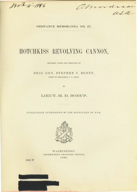
NOTE.<br />
This description of the <strong>Hotchkiss</strong> revolving cannon pertains to the<br />
Army types, but a brief notice of the naval guns appears in tlte Appendix.<br />
1. 1<br />
he breech mechanism of the 1.85-in
11<br />
face, thus forming an iriclined plane, by which the c .. u-tridgeR, as they travel<br />
on it, are gradually forced into the barrels from the point they have been<br />
left by the loading-piston. Directly below the shaft-bearing is the recess<br />
containing two holes for the recoil-plateN'.<br />
On the under sifle of the breech and in the front half a passage 1s<br />
formed through which the withdrawn ca:;cs are expelled. A small chq,nnel,<br />
2', Fig. 1, Plate III, leads obliquely from the firing-pin close behind the<br />
recoil-plate; through it the point of the pin can drop out, in case it iK accidentally<br />
broken.<br />
Towards the rear is the bed for the head of the elevating-screw, aml<br />
around it are tapped holes for the assembling-screws of the cover-plate. (See<br />
Fig. J, Plate VI.)<br />
On the upper face, to the left and front, is the loa
16<br />
TilE IGllTS.<br />
The rear sight.-rrhe rear sigltt (Plate V) cun::;i t::; of tho tem, slide,<br />
and ·upport. The ·tem, uitahly graduated, is a traigbt piece of bra .·, tho<br />
cro s-section being triangular with rounded corn •rs. The slide i' a , mall<br />
box placed on the head of the stem, and capable of being moved perpendicularly<br />
to it by mean, of a crew working in a. nut in it encl. This<br />
screw terminates on the right in a milled head, and on the left in a journal<br />
wlticlt revolves in the left end of the box. The shape of thi enJ. i · fini8hed<br />
to corre. ponc1 to tlte other. 1\vo Ret- crews pas· through it into an<br />
annular O'l'Oove in the journal. By thi · device the screw is only withdrawn<br />
from the l>Ox when the set- crew are renewed. A plate is fa. tened<br />
to the upper side of the b x, and Ita the ighting-notch and graduation on<br />
it top and rear faces, respectively.<br />
The support i · a lm1s. casting fastened to the rear of the right frame<br />
bar, and is piercerl with a canal for the tern. A. top- crew, bearing ao·ainst<br />
a flat 'pring, sen-eH to retain the stem at the desired elevation. The downward<br />
tra,·el1s limited by a should r below the heaL! of the stem. T l1e ·topscrew<br />
iu prevente 1 from being accidentally lo t by having a retainino·<br />
.·boulder on its inner end. The screw is originally in e1ted tltrouglt the<br />
chn.nnel formed in the prolongation of it bell. The head i · ·ubscq uentl.>'<br />
fa ·tenecl to the screw.<br />
shown in Fig. 7.<br />
The rece in which the retaining :;houlder lies i ·<br />
The front sight.-The front sight is a piece of steel divided into a<br />
thren,ded ba e, a.n n.nnular shoulder, a.nd a hexagonal .tern, terminating ill<br />
a cone. The latter i::; ronghenecl to prevent glare. The position of tlti:<br />
sight varic , it hein
18<br />
rrJ1is brake is used both £ r firino· and trav ling, and in the latter case<br />
ba the ad vantage of not requiring a top page of the carriage to a
tie in it ·imilar to the no e of tbe projectile, the top being bored corre<br />
sponding-ly. Owing to the tep a.rrangeme11t the Leads of the cartridge<br />
project above the cover in a similar manner so as to come readily to tl1e<br />
hand.<br />
THE FLANK-DEFENSE GUN.<br />
The flank-defen e gun i de igned as a defensive weapon to effectually<br />
cover the clitcbes and approaclte of permanent fortification , and to offer<br />
a.n effective obstruction to the siege operations of an enemy.<br />
rrhe theory of this piece i given in Ordna11ce Notes, No. 178, a tran -<br />
lation from the French, by Lieutenant (now Captain) Birnie. 'I'he following<br />
is a brief abstract of the principle of con. truction :<br />
"If we fire from a rifled gun tube a projectile ca e inclo ing a number<br />
of similar balb arranged in layers, ·o that the center of g-ravity of each<br />
ball is equally distant from the axial line of the case, and arrange the case<br />
to take the rifling and to remain intact during its passage through the tube,<br />
but to open when it leaves the tnbe, then the ball will spread in a sheaf<br />
like surface, or gm·be, of which t.he angle at the ummit will depend upon<br />
the twist of the rifling and the O'eneral forrn upon the cnrvature of the indi<br />
vidual trajectories of the balls. \Ve can hence calculate the element of<br />
the /}erbe."<br />
* * * "By properly calculating the twi ·t of the rifling of the<br />
second tube, the .r;erues of ball may be delivered o tlmt the dangerous<br />
zones of the two will be joined"<br />
"By succe"ively briugitw to the ·nnw position a series of ri:A.ell tubes<br />
arranged to give dangerous zones succe· ively interior to and joining each<br />
other, we can form a continuon dangerous zone." * * *<br />
"rrhe llotcltkiss revol v.ing cannou practically realize· this conception;<br />
it lnt ·five tubes which occupy, ucce ::;ively, exactly tlte same po ·ition at<br />
the moment of firing. rrhe ditch is searched from the point * * *<br />
w l1icb correspond. to the tube giving the oTeatest di persion, by rifling tlte<br />
tube::; with a twi t separately cal ulated for each, an l by giving the piece<br />
an in lination dependent upon th l1eig·ht * * * of the line of fire of<br />
the caponiere."
37<br />
the receiver by turning the handle backwards. Generally this cartridge is<br />
so tightly wedged in that it cannot be withdrawn by the hand or the screwdriver.<br />
In that event it is driven out by the rammer, the case removed,<br />
and the service continued.<br />
(k) If the stoppage of the turning has any cause other than those mentioned,<br />
which is not immediately recognized, the firing-pin and ammunition<br />
are removed, and the gun thoroughly gone over.<br />
In the first place, the proper position of the barrels in the disks is to De<br />
examined to ascertain if the lines on the barrels are opposite those on the<br />
rear disk. If no essential deviation is found here, then a search is to be<br />
made to see whether the revolution is obstructed by any little bur, which<br />
has formed on the butt-plate, either through the rubbing of the firing-pin<br />
or by defects in the cartridge-head. rro ascertai11 this a thin plate is put<br />
between the butt-plates and rear disk. Generally burs are effaced by the<br />
action of the cartridges themselves, but sometimes they produce no effect<br />
on them. When this is the case, the group of barrels must be separated<br />
from the breech, and the obstructions cleared away by the armorer, who<br />
must not remove any metal from the butt-plate.<br />
In addition, the movement may be impeded through injury to the<br />
meebanism in consequence of insufficient care in putting together the worm<br />
and pin wheel the mainspring and fiting-pin or extractor-crank and link<br />
The damaged parts are to be well oiled, and the crank turned to see if the<br />
difficulty cannot be oLviated by the mutual rubbing of the various members.<br />
If this is not sufficient the armorer must attend to the matter. The<br />
use of sharp instruments is prohibited.<br />
If the examination should reveal a deviation between the lines on any<br />
of the barrels and the corresponding ones on the rear disk, it shows that<br />
the barrel in question no longer occupies its proper position. This is of<br />
importance ouly when the space between the barrel and butt-plate has been<br />
diminished to such an extent that the extractor-hooks are ground by the rotation,<br />
or the ·cartridge-head strikes the plate before it is in the firing position.<br />
In this case the repairs needed are of a more serious nature, since, in general,<br />
the disks will have to be repl aced by new ones.
38<br />
Any screwing of the barrels is forbidden, except when it is noticed<br />
that the arinding of the extractor-hooks is beeoming so considerable that<br />
the further use of the gun is endangered. Only rarely hould a loosened<br />
barrel be screwed back into the disk.<br />
Finally, in order that no interruption should occur in the firing, the<br />
feed-trough should always be supplied with ammunition and the crank<br />
turned with perfect uniformity. The habitual rate is thirty revolutions per<br />
minute, which may be increa ed to 'ixty in exceptional cases. Whenever<br />
the gunner at the crank experiences any difficulty in turning, he should<br />
promptly stop, and the cause sear bed for, which will probably be found in<br />
one of the foregoing.<br />
UNLOADING.<br />
After the order is given to cease fire, the cartridges remaining in the<br />
barrels must not be discharged, but the gun is to be unloaded in the followmg<br />
way:<br />
Open the breech-door and let it down carefully; that is, care should<br />
be taken that it does not fall down. rrake out the firing-pin and turn the<br />
group of barrels back by mean of the crank, bringing the loaded barrels<br />
successively in front of the loading-trough, where the cartridges are<br />
removed. This is done either with the fingers or else by putting the end<br />
of the screw-driver between the cartridge-head and the barrel, and pushing<br />
the cartridge into the trough. Should it fit the barrel too closely, the rammer<br />
is inserted in the barrel from the muzzle, and the cartridge carefully<br />
driven out. In this case, in order to avoid any chance of injury occurring<br />
to the gunners, a light rope is fa tened to that pmt of the staff projecting<br />
from the muzzle, the end of the rope being in the hands of tlte necessary<br />
men, who then haul back on the line.<br />
It is strictly forbidden to unload the piece with the extractor while<br />
turning the crank, because by so doing the case i easily torn from the projectile,<br />
or at least loosened, and the cartridge rendered useless.<br />
M.A.NAGEM}]NT AFTER FIRING.<br />
After firing, the gun, as a rule, can be clean eu without eli mounting<br />
the mechanism, because the cartridges when properly fabricated allow no
39<br />
escape of gas to the rear, and hence fouling of the parts in the breech can<br />
occur but to a small extent. In this case, the barrels are carefully and<br />
thoroughly washed with soap and water, dried, and oiled with a flannel<br />
rag. The gun should be elevated, and the barrels be brought successively<br />
in front of the ejector-hole and then washed, in order to prevent any water<br />
entering the breech and fouling the mechanism. The latter is thoroughly<br />
wiped throughout with cotton waste and oiled, the crank being turned to<br />
aid the operation. On the exterior the barrels are washed with fresh water<br />
and dried.<br />
After long use the entire piece should be thoroughly cleaned.<br />
The interior.-(a) The barrels.-Having dismounted the breech mechanism,<br />
depress the gun so that the water will escape through the muzzle,<br />
bring each barrel successively in front of the loading-trough, close its rear<br />
end by a wooden plug (kept in the equipment-chest) surrounded by a<br />
greased rag, wet the sponge, introduce it in the muzzle, and continue until<br />
the water issues in as clear a state as it enters. Dry the bore with rags<br />
placed on the end of the staff.<br />
(b) The mechanism.-Wash and dry, successively, with the greatest<br />
care those parts of the mechanism which have been fouled dw·ing the firing,<br />
viz, the point of the firing-pin, the extractor-hooks, link, and rack, the cogwheel,<br />
the loading-piston and rack, the extractor-crank. Wash and dry the<br />
exterior of the worm. Clean the worm-shaft, the mainspring, and button<br />
with dry rags. '1\·eat in the same way such parts of the interior of the<br />
breech as are not varnished, particularly the channels of the firing-pin<br />
and loading-piston; the latter with a wiper-brush covered with cloth.<br />
crew-holes, bearings for the worm-shaft, breech-door hinge, pin and channel<br />
of the button must be similarly cleaned. Those portions of the breech<br />
from which the varnish has disappeared should be given a coating in the<br />
manner described below.<br />
The exterio'r.-The entire piece may be washed and dried, and those<br />
parts which are not varnished or lacquered (the barrels, for example) should<br />
be oiled. 'l,he butt-plate and entire front face of the breech can be cleaned<br />
by a rag wrapped around a flat copper strip, and put between the breech<br />
and rear disk.
46<br />
flanged casting bolted to the rail of the deck or a pedestal similarly secured<br />
to the deck. This piece with it fork can be shifted from one carriage to the<br />
other. There are two clamp provided, one for locking the pivot and the<br />
other the trunnions (see Plate XV).<br />
For land service the carriage resemble the Army one in size and<br />
weight, but the trunnion-saddle i replaced by the pivot- ocket, o that the<br />
gun with it fork can be tran ferred to it. The elevating apparatus is also<br />
modified, and the limber is arranged for hand draft.<br />
The I 85-inch gun.-lts w io·ht being too great for hand draft, thi,<br />
piece ha n0 laud-carriage. For u eon hip the mount· ar imilar to those<br />
tor the 1.45-inch gun, viz, the rail and the deck mount. The latter i called<br />
the ''crinoline carriage," from its hape.<br />
The boat-carriage is of a peculiar type, consi ting of a heavy bed-plate,<br />
mounted on rollers for fore and aft tnw r e; and ltaving a pivot-bolt at each<br />
end and a lm·a·e pivot in the center. On this central pivot is mounted a<br />
gun-carriage, whose rear end is arranged with tran. verse gear which connects<br />
with its bed-plate. This carriage also ha eleva.ting-o·ear.<br />
The 2.1-inch gun.-Thi piece has but one carriage, that for the deck,<br />
the boat, land, and rail mounts beino- omitted. It consists (Plate XXII) of<br />
heavy circular bed-plate provided with bolt-holes for securing to deck.<br />
The central part is rai::;eu all(l fa tened to another disk, the curved stu-face<br />
of which is provided with teeth. 1 1 he t p carriage i compo ed of two trapezoidal-shaped<br />
bracket:;, comtected by transoms, and furnished with the usual<br />
elevatino· apparatus. The pivot, which j central, pa :;es through the bed,<br />
the carriage being non-recoil. The traversing handle is on the left. It is<br />
connected by bevel-wheel to the worm-shaft, pas. ing through the brackets.<br />
The worm-thread gears in the teeth on the upper plate.<br />
guns.<br />
THE EQUIPMENTS.<br />
1 1 hese do not differ e eHtially fr m those snpplied with the Army


