Roundway Bearings Installation Instructions - Thomson
Roundway Bearings Installation Instructions - Thomson
Roundway Bearings Installation Instructions - Thomson

Create successful ePaper yourself
Turn your PDF publications into a flip-book with our unique Google optimized e-Paper software.
3<br />
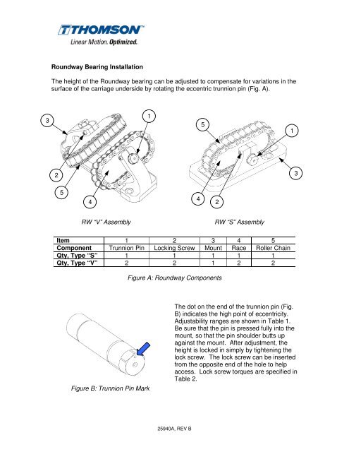
<strong>Roundway</strong> Bearing <strong>Installation</strong><br />
The height of the <strong>Roundway</strong> bearing can be adjusted to compensate for variations in the<br />
surface of the carriage underside by rotating the eccentric trunnion pin (Fig. A).<br />
2<br />
5<br />
4<br />
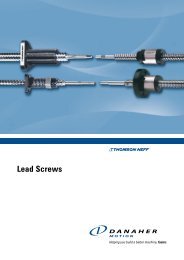
RW “V” Assembly<br />
Item 1 2 3 4 5<br />
Component Trunnion Pin Locking Screw Mount Race Roller Chain<br />
Qty, Type “S” 1 1 1 1 1<br />
Qty, Type “V” 2 2 1 2 2<br />
Figure B: Trunnion Pin Mark<br />
1<br />
Figure A: <strong>Roundway</strong> Components<br />
The dot on the end of the trunnion pin (Fig.<br />
B) indicates the high point of eccentricity.<br />
Adjustability ranges are shown in Table 1.<br />
Be sure that the pin is pressed fully into the<br />
mount, so that the pin shoulder butts up<br />
against the mount. After adjustment, the<br />
height is locked in simply by tightening the<br />
lock screw. The lock screw can be inserted<br />
from the opposite end of the hole to help<br />
access. Lock screw torques are specified in<br />
Table 2.<br />
25940A, REV B<br />
4<br />
5<br />
2<br />
RW “S” Assembly<br />
1<br />
3
Assembly Size 16 24 32 48 64<br />
“S” Type Adjustability (in.) +/- .020 +/- .020 +/- .020 +/- .040 +/- .040<br />
“V” Type Adjustability (in.) +/- .015 +/- .015 +/- .015 +/- .030 +/- .030<br />
Table 1: <strong>Roundway</strong> Adjustability Ranges<br />
Assembly Size 16 24 32 48 64<br />
Screw Thread 10-32 10-32 1/4-20 3/8-16 7/16-14<br />
Seating Torque (in-lbs) 60 60 100 350 580<br />
<strong>Roundway</strong> Bearing Preloading<br />
Table 2: Locking Screw Seating Torques<br />
The eccentric trunnion pins provide a simple means for preloading <strong>Roundway</strong> bearings<br />
in those applications where no play can be tolerated. However, preloading should be<br />
applied only to give the required rigidity. Excessive preloading will cause unnecessary<br />
friction and wear.<br />
A suggested procedure is to align the bearings to the point that all rollers circulate<br />
continuously as they are moved. This is a line-to-line fit. Next, gradually increase the<br />
preload until the desired rigidity is achieved. This is determined by applying the external<br />
load and measuring the deflection with an indicator. While increasing the preload,<br />
measure or feel the rolling friction. A sudden increase in friction indicates excessive<br />
preloading.<br />
While the <strong>Roundway</strong> bearing is self-aligning in all directions, care should be taken when<br />
installing the bearings and shafting. Excessive variations in running parallelism can lead<br />
to additional preloading of the bearings.<br />
Lubrication<br />
The <strong>Roundway</strong> bearings should be lubricated to increase the bearing life and minimize<br />
corrosion of the bearing surfaces. Grease lubrication is usually recommended for<br />
<strong>Roundway</strong> bearings, as grease will provide adequate lubrication and sealing is<br />
simplified. The choice of the grease to use for a specific application should be based on<br />
conditions of temperature, speed and nature of the environment.<br />
It is recommended that you lubricate the <strong>Roundway</strong> bearing prior to installation and<br />
periodically during operation to assure that the bearing does not run dry.<br />
25940A, REV B