Transmission Chain catalogue
Transmission Chain catalogue
Transmission Chain catalogue

Create successful ePaper yourself
Turn your PDF publications into a flip-book with our unique Google optimized e-Paper software.
Roll-Ring®<br />
Self Adjusting <strong>Chain</strong> Tensioner<br />
Case study: chocolate production<br />
A major chocolate manufacturer was<br />
experiencing serious problems with short<br />
chain life on a main production line and also<br />
had chain tensioning problems, due to the<br />
inaccessibility of the chain drives. Firstly, the<br />
short chain life (4-5 weeks) was overcome<br />
when the Renold Engineer recommended a<br />
change to nickel plated chains, which led to a<br />
new chain life of more than twelve months.<br />
Secondly, regular downtime due to the failure<br />
of the previous chains was extended through<br />
the fitting of chain tensioners and their<br />
ongoing adjustments over time. With a time<br />
sensitive maintenance policy, the chocolate<br />
manufacturer looked for a solution to speed<br />
up the tensioning of the replacement chain<br />
and Roll-Ring® provided that simple solution.<br />
The new Renold chain had to be adjusted to be<br />
near their ideal centres when fitted, and when<br />
the maximum compression was reached the<br />
Roll-Ring® was fitted by hand within seconds.<br />
No further adjustments had to be carried out<br />
due to the flexibility of the Roll-Ring® design<br />
and all future chain extension is automatically<br />
taken up during the chain’s life. With a large<br />
reduction in equipment downtime for tensioning<br />
adjustment, the chocolate manufacturer now<br />
enjoys significant time savings, cost savings<br />
and peace of mind.<br />
Roll-Ring® chain<br />
tensioners in one<br />
of our test rigs<br />
• Saving of maintenance time for<br />
tension adjustments<br />
• Simple installation<br />
• Effective dampening<br />
• Unique solution<br />
The new principle<br />
The principle of the Roll-Ring® chain tensioner<br />
is based on two simple phenomena:<br />
• The elastic ring engages with the chain<br />
drive strands and rolls between them in<br />
a pre-stressed condition taking up the<br />
shape of an ellipse<br />
• The constantly opposing movements of the<br />
load and slack strands cancel each other out,<br />
thereby holding the Roll-Ring® in position<br />
Installation and maintenance<br />
Roll-Ring® chain tensioners are maintenance<br />
free and can be fitted to a wide variety of<br />
chain drives with no installation down time.<br />
The requirement is that:<br />
• There is a working space with a gap between<br />
the chain strands which is smaller than the<br />
reference diameter of the chain tensioner<br />
• There is a sufficient gap between the chain<br />
drive sprockets<br />
We recommend that the chain tensioner is<br />
positioned between two chain strands such<br />
Roll-Ring® chain<br />
tensioners are<br />
re-cyclable<br />
Renold <strong>Transmission</strong> <strong>Chain</strong> Catalogue I 65<br />
that there is at least one chain pitch between<br />
the Roll-Ring® and the smallest sprocket.<br />
The Roll-Ring® can also be positioned just as<br />
effectively outside this recommended area,<br />
as long as it is sufficiently prestressed. In this<br />
case, practical trial and error are recommended.<br />
Roll-Ring® chain tensioners can be used in line<br />
within the same chain strand, or parallel with<br />
each other in multi-strand chain drives.<br />
Please note that triplex chain drives only<br />
require two Roll-Rings® positioned on the<br />
outer strands.<br />
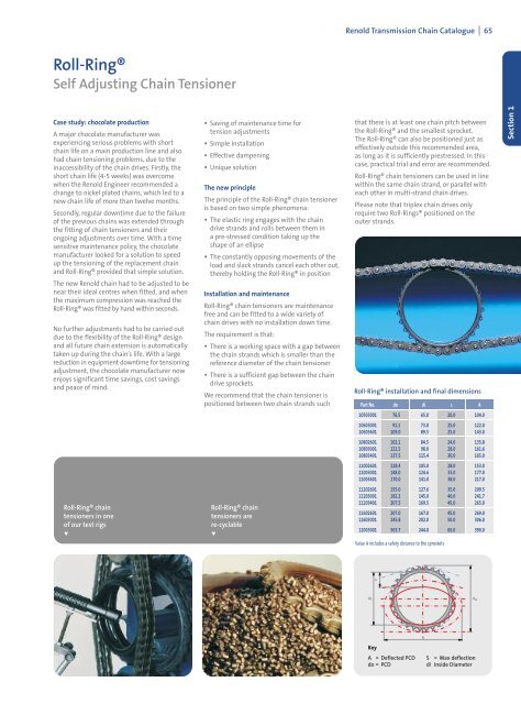
Roll-Ring® installation and final dimensions<br />
Part No. do di s A<br />
10503001 76.5 65.0 20.0 104.0<br />
10603001 91.1 73.0 25.0 122.0<br />
10603601 109.0 89.5 25.0 143.0<br />
10802601 102.1 84.5 24.0 135.8<br />
10803001 121.5 98.0 28.0 161.6<br />
10803401 137.5 115.4 30.0 165.0<br />
11002601 128.4 105.0 28.0 153.0<br />
11003001 148.0 124.6 33.0 177.0<br />
11003401 170.0 141.0 38.0 217.0<br />
11202601 155.0 127.6 35.0 209.5<br />
11203001 182.2 145.0 40.0 241.7<br />
11203401 207.5 169.5 45.0 265.0<br />
11602601 207.0 167.0 45.0 269.0<br />
11603001 245.8 202.0 50.0 306.0<br />
12003001 303.7 244.0 60.0 390.0<br />
Value A includes a safety distance to the sprockets<br />
Key<br />
A = Deflected PCD<br />
do = PCD<br />
S = Max deflection<br />
di Inside Diameter<br />
Section 1