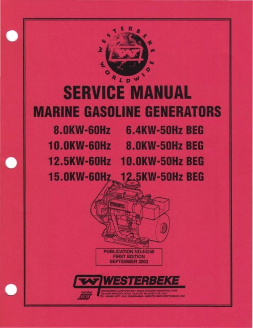
service manual 44240 8.0, 10.0, 12.5 and 15.0 - Westerbeke
service manual 44240 8.0, 10.0, 12.5 and 15.0 - Westerbeke
service manual 44240 8.0, 10.0, 12.5 and 15.0 - Westerbeke

Create successful ePaper yourself
Turn your PDF publications into a flip-book with our unique Google optimized e-Paper software.
Gasoline with an ETHANOL content<br />
higher than 10% (E10) is not allowed<br />
<strong>and</strong> may void warranty.<br />
Engines & Generators
)<br />
)<br />
)
HOW TO DETERMINE ENGINE OVERHAUL PERIOD<br />
Cause of Low Compression<br />
Generally, the time at which an engine should be overhauled<br />
is detennined by various conditions such as lowered engine<br />
power output, decreased compression pressure, <strong>and</strong> increased<br />
fuel <strong>and</strong> oil consumption. The lowered engine power output<br />
is not necessarily due to trouble with the engine itself, but is<br />
sometimes caused by wom plugs or fueVcarburetor<br />
problems .. The decrease in compression pressure is caused<br />
by many factors. It is, therefore, necessary to detennine a<br />
cause or causes on the basis of data produced by periodic<br />
inspection <strong>and</strong> maintenance. Oil analysis on a seasonal basis<br />
is a good means of monitoring engine internal wear. When<br />
caused by wom cylinders or piston rings, the following<br />
symptoms will occur:<br />
1 Low engine power output<br />
2 Increased fuel consumption<br />
3 Increased oil consumption<br />
4 Hard engine starting<br />
5 Noisy engine operation<br />
These symptoms often appear together. Symptoms 2 <strong>and</strong> 4<br />
can result also from carburetor performance or worn plugs.<br />
They are caused also by defective electrical devices such as<br />
the battery, alternator or starter. Therefore it is desirable to<br />
judge the optimum engine overhaul time by the lowered<br />
compression pressure caused by worn cylinders <strong>and</strong> pistons<br />
plus increased oil consumption. Satisfactory combustion is<br />
obtained only under sufficient compression pressure. If an<br />
engine lacks compression pressure, incomplete combustion<br />
of fuel will take place even if other parts of the engine are<br />
operating properly. To detennine the period of engine<br />
overhaul, it is important to measure the engine compression<br />
pressure regularly. At the same time, the engine speed at<br />
which the measurement of compression pressure is made<br />
should be checked because the compression pressure varies<br />
with engine rpm. The engine rpm can be measured at the<br />
front end of the crankshaft.<br />
When the decrease of compression pressure reaches the<br />
repair limit, the engine must be overhauled.<br />
The engine requires overhaul when oil consumption is high,<br />
blow-by evident, <strong>and</strong> compression valves are at minimum or<br />
below.<br />
TESTING FOR OVERHAUL<br />
NOTE: Make cenain the engines valve clearances are<br />
properly adjusted. An incorrect valve clearance can cause<br />
symptoms that might, incorrectly, suggest an engine<br />
overhaul (cylinder misfire, white smoke, noise, etc).<br />
Before preparing for an engine overhaul, adjust the valve<br />
clearances to the correct specification. install a new cover<br />
gasket <strong>and</strong> test the engine.<br />
DISASSEMBLY<br />
-..v: WESTERBEKE<br />
Engines & Generators<br />
3<br />
NOTE: Before disassembly <strong>and</strong> cleaning, carefully check<br />
for defects which cannot be found after disassembly <strong>and</strong><br />
cleaning.<br />
• All disassembled parts should be carefully arranged in<br />
the order of reassembly. Mark or label the parts as<br />
needed to insure proper mating <strong>and</strong> reassembly in the<br />
proper directions <strong>and</strong> positions.<br />
• If the disassembly procedure is complex requiring many<br />
parts to be disassembled, the parts should be disassembled<br />
in a way that will allow them to be efficiently reassembled<br />
without any change in the engine's extemal appearance or<br />
its performance.<br />
• Do not remove or disassemble parts that require no<br />
disassembly.<br />
• Carefully inspect each parts after removal for damage,<br />
deformation, <strong>and</strong> other problems.<br />
• Carefully check gaskets, packings <strong>and</strong> oil seals, even if<br />
checking is not specified. Replace with new ones if defective.<br />
• Be careful not to damage the disassembled parts. Keep the<br />
parts clean.<br />
• Use the proper tools. Apply oil when necessary. Take<br />
special care to keep the fuel system parts free from the<br />
intrusion of dust <strong>and</strong> dirt.
The following engine troubleshooting guide may be helpful in<br />
detennining if a complete or partial overhaul is necessary.<br />
Insomclen! Power InsuHlclen! Compression<br />
Compression leakage from valve seat<br />
Seized valve stem<br />
Weak or broken valve spring<br />
Burned cylinder head gasket<br />
Cracked or distorted cylinder head<br />
Sticking, damaged, or worn piston<br />
ring<br />
Cracked or worn piston<br />
TROUBLESHOOTING GUIDE<br />
Malfunction of Fuel System<br />
Malfunction ollgnllion System<br />
Excessive 011 Consumption 011 Worklng Up<br />
Worn or sUcking piston ring or piston<br />
ring groove<br />
Worn plslon or cylinder<br />
011 Worklng Down<br />
Bad valve seal<br />
Worn valve stem or guide<br />
011 Leakage<br />
Dlfllcull starting Malfunction 01 Englne-relaled<br />
Components<br />
Burned valve<br />
Worn pislon, plslon ring, or cylinder<br />
Burned cylinder head gasket<br />
Mallunctlon 01 Fuel System<br />
Mallunction of Electrical System<br />
Abnonnal Combusllon Mallunction of Engine-mlaled<br />
Components<br />
SUcking or burned valve<br />
Weak or broken valve spring<br />
Carbon accumulated in<br />
combusllon chamber<br />
Malfuncllon 01 Fuel Syslem<br />
Mallunctlon ollgnillon Syslem<br />
Poor Idling Mallunctlon of Englne-mlaled<br />
Components<br />
Poor valve-to-valve seal contact<br />
Failure of cylinder head gasket<br />
Malfunction of Fuel Syslem<br />
Malfunction of Ignition<br />
System<br />
Engine Noise Crankshaft or bearing mlaled<br />
parts .<br />
Excessive main bearing oil clearance<br />
Main bearing seized or heat damaged<br />
Excessive crankshaft end play<br />
Excessive connecting rod bearing oil<br />
clearance<br />
Connecting rod bearing seized or hea<br />
damaged<br />
Piston mlaled parts<br />
Worn Cylinder<br />
Worn piston or piston pin<br />
Seized plstpn<br />
Damaged piston ring<br />
Bent Connecting Rod<br />
Malfuncllon ollgnilion Syslem<br />
Valve or timing relaled parts<br />
Malfunction of HLA *<br />
Broken valve spring<br />
Excessive clearance between valve<br />
stem <strong>and</strong> guide<br />
InsuHlcient lubrication of rocker arm<br />
Others<br />
Malfunction of water pump bearing<br />
Malfunction of attemator bearing<br />
Malfunction of timing belt tensioner<br />
Engine Misfires Poor quality fuel.<br />
Incorrect timing.<br />
Dirty flame arrester.<br />
Cracked distributor cap.<br />
Faulty Ignnlon wires.<br />
Spark plugs are worn.<br />
High exhaust back-pressure.<br />
Valve clearances are incorrect.<br />
Engine Backfires Spark plug wires are connected<br />
wrong.<br />
Incorrect timing.<br />
Engine is flootiad.<br />
Dirty flame arrester.<br />
Cracked distributor cap.<br />
High exhaust back-pressure.<br />
Choke Is stuck closed.<br />
* Tapet noise may occur if the engine is not operated for a<br />
period of time. Tapet noise should stop within J 0 minutes<br />
after operating the engine.<br />
Engln"s. & Generators<br />
4
TROUBLESHOOTING GUIDE<br />
Engine Overheats Coolant loss. Pressure test cooling<br />
system.<br />
Faulty raw water pump impeller.<br />
Belts are loose or broken.<br />
Raw water pump worn.<br />
Faulty thermostat.<br />
Heat exchanger is clogged.<br />
Collapsed hose.<br />
Low 011 Pressure Low oil level.<br />
Faulty oil pressure sender<br />
Wrong SAE type oil in the engine.<br />
Faulty gauge<br />
Wrong type oil filter.<br />
Relief valve is stuck.<br />
Faulty oil pump.<br />
Faulty engine bearings.<br />
Starting Battery Loose alternator drive belt<br />
Faulty battery voltage regulator.<br />
Connections to the alternator are loose<br />
or faulty.<br />
Faulty alternator.<br />
No excitation to the regulator<br />
High 011 Pressure Faulty sender or gauge<br />
Di';% oil or wrong SAE type oil in the<br />
eng ne.<br />
Relief valve is stuck.<br />
Blue Exhaust Smoke Lube oil is diluted.<br />
Discharge from the Engine High lube oil level.<br />
Crankcase breather hose is clogged.<br />
Valves are worn or adjusted<br />
incorrectly.<br />
Piston rings are worn or unseated.<br />
Black exhaust smoke Dirty flame arrester.<br />
Discharge from the Engine Faulty carburetor.<br />
Idle mixture jet too rich.<br />
Accelerator diaphragm leaking.<br />
Valves are worn or incorrectly<br />
adjusted.<br />
Lube oil is diluted.<br />
Piston rings are worn or unseated.<br />
NOTE: The engines control system (electrical system) is<br />
protected by a 20 Ampere <strong>manual</strong> reset circuit breaker<br />
located just outboard of the starter motor.<br />
-..v- WESTERBEKE<br />
Englnes'& Generators<br />
5
DISASSEMBLY AND ASSEMBLY PROCEDURES<br />
DISASSEMBLY<br />
• Before disassembly <strong>and</strong> cleaning, carefully check for<br />
defects which cannot be found after disassembly <strong>and</strong><br />
cleaning.<br />
• Drain water, fuel <strong>and</strong> oil before disassembly.<br />
• Clean or wash the engine exterior.<br />
• Do not remove or disassemble parts.<br />
• Perform disassembly in a proper order using proper tools.<br />
Keep disassembled parts in order. Apply oil when<br />
necessary. Take special care to keep the fuel system parts<br />
from intrusion of dust <strong>and</strong> dirt.<br />
• Parts must be restored to their respective components from<br />
which they were removed at disassembly. This means that all<br />
parts must be set aside separately in groups, each IIllIIked for<br />
its component, so that the same combination or set can be<br />
reproduced at assembly.<br />
• Pay attention to marks on assemblies, components <strong>and</strong><br />
parts for their positions or directions. Put on marks, if<br />
necessary, to aid assembly ..<br />
• Carefully check each part or component for any sign of<br />
faulty condition during removal or cleaning. The part will<br />
tell you how it acted or what was abnormal about it more<br />
accurately dm!ng removal or cleaning.<br />
ASSEMBLY<br />
• Wash aU parts, except for oil seals, O-rings,<strong>and</strong> rubber<br />
gaskets with cleaning solvent <strong>and</strong> dry them with air<br />
pressure .<br />
• Always use tools that are in good condition <strong>and</strong> be sure<br />
you underst<strong>and</strong> how to use them before performing any<br />
job.<br />
• Use only good quality lubricants. Be sure to apply a coat<br />
of oil, grease or sealant to parts as specified ..<br />
• Be sure to use a torque wrench to tighten parts for which<br />
torques are specified.<br />
• When the engine is assembled,install new gaskets <strong>and</strong><br />
O-rings.<br />
TORQUING DATA<br />
Parts of the engine use plastic region tightening bolts. The<br />
tightening procedure for these is different from that of<br />
conventional bolts <strong>and</strong> is described in this <strong>manual</strong>, Note that<br />
plastic region tightening bolts have fixed <strong>service</strong> limitS.<br />
These limits are indicated in this <strong>manual</strong> <strong>and</strong> must be strictly<br />
observed.<br />
• Plastic region tightening bolts are used for the following<br />
applications:<br />
1. Cylinder head bolts<br />
2. Connecting rod cap bolts<br />
• The tightening procedure is basically as follows: After<br />
tightening a bolt to the specified torque, tighten it by a<br />
further 90" + 90" or by a further 90-100". The exact<br />
tightening procedure differs depending on the bolt <strong>and</strong> is<br />
described where it applies in this <strong>manual</strong>.<br />
".. WESTERBEKE<br />
Engines & Generators<br />
8<br />
GASKET INFORMATION<br />
The engine has several areas where form-in-place RTV<br />
silicone gaskets are used such as LOCTITE 598 or GE<br />
RTV 100. To ensure that the gasket fully serves its pmpose,<br />
it is necessary to observe some precaution when applying the<br />
gasket. Bead size, continuity <strong>and</strong> location are very important.<br />
Too thin a bead could cause leaks <strong>and</strong> too thick a bead could<br />
be squeezed out of location causing blocking or narrowing of<br />
the fluid feed lines. To eliminate the possibility of leaks from<br />
a joint, it is necessary to apply the gasket evenly without a<br />
break while observing the correct bead size.<br />
The gasket material used in the engine is a room temperature<br />
vulcanization (RTV) type <strong>and</strong> is supplied in a l40z (400<br />
gram) applicator/tube. The RTV hardens as it reacts with the<br />
moisture in the atmospheric air <strong>and</strong> can be used for sealing<br />
both engine oil <strong>and</strong> coolant assemblies.<br />
Disassembly<br />
The parts assembled with the silicone can be easily<br />
disassembled without use of a special method. In some cases,<br />
however, the sealant between the joined surfaces may have<br />
to be broken by lightly striking with a mallet or similar tool.<br />
A flat <strong>and</strong> thin gasket scraper may be lightly hammered<br />
in between the joined surfaces. In this case, care must be<br />
taken to prevent damage to the joined surfaces. For removal<br />
of the oil pan, use a special "oil pan remover".<br />
Surface Preparation<br />
Thoroughly remove all substances deposited on the gasket<br />
application surfaces using a gasket scraper or wire brush.<br />
Check to ensure that the surfaces to which the silicone gasket<br />
is to be applied is flat. make sure that there are no oils,<br />
greases <strong>and</strong> foreign substances deposited on the application<br />
surfaces. Do not forget to remove the old sealant that<br />
remains in the bolt holes.<br />
Form-in-place Gasket Application<br />
When assembling parts with the silicone gasket, you must<br />
observe some precautions but the procedures are very simple<br />
as in the case of a conventional precut gasket.<br />
The applied gasket bead should be the specified size <strong>and</strong><br />
without breaks. Be sure to encircle the bolt hole circumference<br />
with a completely continuous bead. The gasket material<br />
can be wiped away unless it has hardened. While the gasket<br />
is still moist, mount the parts in position. When the parts are<br />
mounted, make sure that the gasket is applied to the required<br />
area only. Do not apply oil or water to the sealing locations<br />
or start the engine until a sufficient amount of time has<br />
passed after installation is completed.<br />
The gasket application procedure may vary on different<br />
areas. Observe the procedure described in the text when<br />
applying the gasket silicone <strong>and</strong> follow the directions on the<br />
applicator/tube.
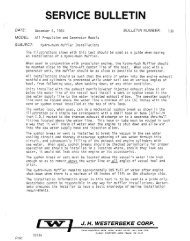
ANGULAR NUT AND BOLT TIGHTENING METHOD<br />
1. Carefully wash the nuts <strong>and</strong> bolts to remove all oil <strong>and</strong><br />
grease.<br />
2. Apply a coat of molybdenum disulfide grease to the<br />
threads <strong>and</strong> setting faces of the nuts <strong>and</strong> bolts.<br />
3. Tighten the nuts <strong>and</strong> bolts to the specified torque (snug<br />
torque) with a torque wrench.<br />
CENTER LINE<br />
LINE<br />
-"--:).l<br />
C D<br />
4. Draw a line (A-B) across the center of each bolt.<br />
5. Draw another line (C-D) on the face of each of the parts<br />
to be clamped. This line should be an extension of the<br />
line (A-B).<br />
COINCIDING LINE<br />
G<br />
6. Draw another line (F-G) on the face of each of the parts<br />
to be clamped. This line will be in the direction of the<br />
specified angle (Q) across the center (E) of the nut or<br />
bolt.<br />
7. Use a socket wrench to tighten each nut or bolt to the<br />
point where the line (A-B) is aligned with the line (F-G).<br />
Example: Specified Angle <strong>and</strong> Tightening Rotation<br />
A 3D· 1/12 of a tum<br />
B 60· 1I6 of a tum<br />
C 90· 1I4 of a tum<br />
D 180· 1I2 of a tum<br />
E 360· One full tum<br />
NEW TIGHTENING METHOD USING PLASTIC REGION TIGHTENING BOLTS<br />
Parts of the engine use plastic region tightening bolts. The<br />
tightening procedure for these is different from that of conventional<br />
bolts <strong>and</strong> is described in this <strong>manual</strong>.<br />
NOTE: The plastic region tightening bolts have fixed <strong>service</strong><br />
limits. These limits are indicated where they occur in this<br />
<strong>manual</strong> <strong>and</strong> must be strictly observed.<br />
Plastic region tightening bolts are used for the following<br />
applications:<br />
1. Cylinder Head Bolts<br />
2. Connecting Rod Cap Bolts<br />
The tightening procedure is as follows:<br />
After tightening a bolt to the specified torque, tighten it by a<br />
further 90· + 90· or by a further 90" to 100·. The exact<br />
tightening procedure differs depending on the bolt <strong>and</strong> is<br />
described as it occurs in this <strong>manual</strong>.<br />
Engines & Generators<br />
9
COOLANT PUMP<br />
ENGINE/GENERATOR DISASSEMBLY<br />
EXHAUST<br />
ELBOW<br />
..-v' WESTERBEKE<br />
Engines & Genera/ors<br />
14<br />
THERMOSTAT<br />
ASSEMBLY<br />
CARBURETOR<br />
EXHAUST MANIFOLD
ENGINE-DISASSEMBLY, INSPECTION AND ASSEMBLY<br />
FRONT OIL SEAL CASE INSTALLATION<br />
APPLY A 3MM<br />
BEAD OF F1P GASKET_ • . UJ'-"<br />
FRONT OIL SEAL INSTALLATION<br />
Apply engine oil to the 01 sea! lip, then push the oil· seal<br />
along the guide by h<strong>and</strong> until it touches the front case. Tap<br />
the oil seal into place using the special tool.<br />
-SPECIAL<br />
TOOL<br />
OIL PAN<br />
-..v- WESTERBEKE<br />
Engines & Generators<br />
21<br />
OIL PAN INSTALLATION<br />
APPLY A 4MM BEAD<br />
OF GASKET<br />
Before insLalling the oil pan, inspect the oil pan drain hose<br />
<strong>and</strong> fittings for cracks <strong>and</strong> wear, replace if necessary.<br />
Clean the mating surfaces of the cylinder block <strong>and</strong> oil pan.<br />
Apply a 4mm bead of fonn·in-place gasket to the outer<br />
circumference of the oil pan flange.<br />
INSTALL A NEW OIL FILTER<br />
Screw the oil filter in until the sealing gasket contacts the<br />
front case, then tighten 3/4 turn.<br />
SPIN·ON<br />
OIL FILTER.<br />
SEALING GASKET<br />
APPLY CLEAN OIL<br />
WHEN ASSEMBLING
)<br />
,<br />
)<br />
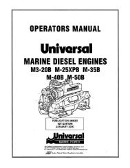
REMOVING THE COOLANT PUMP<br />
1. Loosen the belt guards thumbscrews <strong>and</strong> remove the<br />
engine's belt guard from its brackets at the front of the<br />
engine.<br />
2. Ease the belt tension by releasing the raw water pump<br />
, <strong>and</strong> remove the engine drive belt (on carburetor models it<br />
, will be necessary to remove the governor belt).<br />
3. Unscrew the bolts thai hold the pump to the engine <strong>and</strong><br />
remove the coolant pump.<br />
PULLEY?<br />
COOLANT PUMP<br />
COOLANT CIRCULATING PUMP<br />
IMPELLER<br />
INSPECTION<br />
Carefully check the pump body <strong>and</strong> impeller for cracks <strong>and</strong><br />
damage. Inspect the weep holes for signs of water leakage<br />
<strong>and</strong> rust that would indicate a faulty seal. the pulley should<br />
turn the shaft (<strong>and</strong> impeller) smoothly, without noise or sluggish<br />
rotation <strong>and</strong> the pulley edges should be smooth <strong>and</strong><br />
undamaged.<br />
APPLY A 3MM BEAD<br />
DFGASKET<br />
WATER PUMP INSTALLATION<br />
Apply a 3mm bead of form-in-place gasket to the mounting<br />
surface.<br />
Tighten the mounting bolts a little<br />
at a time.<br />
TORQUE AT 13Nm (9,59 H·lb)<br />
Engines & Generators<br />
28
FAN<br />
HOUSING<br />
EXCITER<br />
TERMINAL<br />
SENSING<br />
TERMINAL<br />
GROUND<br />
TERMINALE<br />
TESTING THE OUTPUT CIRCUIT<br />
WESTERBEKE 51 A MANDO ALTERNATOR<br />
DISASSEMBLY AND TESTING<br />
REAR HOUSING<br />
Y-j'iRMlliALB<br />
1. Connect the positive voltmeter lead to the output<br />
terminal B <strong>and</strong> connect the negative lead to the ground<br />
terminal E on the alternator.<br />
2. Wiggle the engine wiring harness while observing the<br />
voltmeter. The meter should indicate the approximate<br />
battery voltage, <strong>and</strong> should not vary. If no reading is<br />
obtained, or if the reading varies, check the alternator<br />
output circuit for loose or dirty connections or<br />
damaged wiring.<br />
NOTE: Prior to any alterno.tor testing, illSpect the entire<br />
alterno.tor system wiring for defects. Check all cont!ectiollS<br />
for tightness <strong>and</strong> cleanliness, panicularly battery cable<br />
clamps <strong>and</strong> battery terminals. IllSpectthe alternator drive<br />
belt for excessive wear <strong>and</strong> replace if necessary. Also adjust<br />
for proper belttellSion.<br />
p<br />
A WARNING: A failed alternator can become very<br />
hot. Do not touch until the alternator has cooled down.<br />
A WARNING Before starting the engine, make<br />
certain that everyone is clear of moving parts! Keep<br />
away from sheaves <strong>and</strong> belts during test procedures.<br />
A WARNING Multimeters <strong>and</strong> DC Circuits<br />
DC <strong>and</strong> AC circuits are otter mixed together in marine<br />
applications. Always disconnect shore power cords,<br />
isolate DC <strong>and</strong> AC converters <strong>and</strong> shut down generators<br />
before performing DC testing. No AC tests should be<br />
made without proper knowledge of AC circuits.<br />
REFER TO THE<br />
WIRING DIAGRAMS FOR THE ABOVE<br />
WIRING HARNESS CONNECTIONS<br />
TESTING THE EXCITATION CIRCUIT<br />
1. Connect the positive (+)'voltmeter lead to the excitation<br />
terminal R on the alternator <strong>and</strong> the negative (-) lead to<br />
the ground terminal E on the alternator.<br />
2. Turn the ignition switch to the on position <strong>and</strong> note the<br />
voltmeter reading. The reading should be 1.3 to 2.5<br />
volts (see illustration).<br />
3. If the reading is between .75 <strong>and</strong> 1.1 volts, the<br />
rotor field circuit probably is shorted or grounded.<br />
Disassemble the alternator <strong>and</strong> test the rotor as<br />
described under CLEAN AND TEST ALTERNATOR<br />
COMPONENTS in this section.<br />
4. If the reading is between 6.0 <strong>and</strong> 7.0 volts, the rotor<br />
field circuit probably is open. Remove the regulator<br />
<strong>and</strong> inspect it for worn brushes or dirty slip rings.<br />
Replace the brushes if they are less than I14in. (6 mm)<br />
long. If the brushes <strong>and</strong> slip rings are in good condition,<br />
disassemble the alternator <strong>and</strong> test the rotor, as<br />
outlined under CLEAN AND TEST ALTERNATOR<br />
COMPONENTS in this section.<br />
Engines & Generators<br />
43
)<br />
)<br />
SUP b,U',."'"<br />
TEsnNG THE ROTOR<br />
ASSEMBLE ALTERNATOR<br />
MANDO ALTERNATOR SERVICE<br />
FINGERS<br />
1. Carefully press the front bearing into the front housing,<br />
pushing against the bearing's outer race using a bearing<br />
driver. Lock the bearing in place with screws.<br />
TORQUE: 25 - 351b-in (2.B - 4.0 Nm)<br />
OUTER<br />
IIACf<br />
FRONT BEARING ASSEMBLY<br />
ASSEMBLING THE BEARINGS<br />
HOUSING<br />
BEARING LOCKING<br />
SCREWS<br />
FRONT BEARING<br />
2. Place the rotor (pulley end up) on the bed of an arbor<br />
press, on two steel blocks.<br />
3. Press the front housing <strong>and</strong> bearing assembly down<br />
onto the rotor shaft. Press against the bearing's inner<br />
race only, using a sleeve driver. Take care to insure that<br />
the rotor leads clear the steel blocks.<br />
SLEEVE DRIVER<br />
ROTOR<br />
FRONT HOUSING AND<br />
BEARING ASSEMBLY<br />
INSTALLING THE FRONT HOUSING ON THE ROTOR ASSEMBLY<br />
4. Install the rectifier assembly into the rear housing.<br />
5. Insert the Phillips screw <strong>and</strong> tighten it.<br />
RECTIFIER<br />
ASSEMBLY<br />
6. Assemble the front <strong>and</strong> rear housings as follows:<br />
Engines & Generators<br />
48<br />
a. Put the stator winding in the front housing with the<br />
stator leads away from the front housing <strong>and</strong> the<br />
notches in the stator laminations aligned with the<br />
four through-bolt holes in the housing.<br />
b. Align the scribe marks you made in the stator, <strong>and</strong><br />
front <strong>and</strong> rear housings during disassembly.<br />
c. Slip the rear housing into place over the rotor shaft.<br />
Align the mounting holes <strong>and</strong> put the stator leads<br />
through the holes at the top of the rear housing.<br />
d. Install the four bolts <strong>and</strong> tighten them.<br />
TORQUE: 35 - 65/b-tt (4.0 - 7.3 Nm)<br />
NOTE: If the front housing is new, the through-bolt<br />
will not be tapped.
DESCRIPTIDN<br />
TIuJ .fllrte, can be roughly divided into the following sections:<br />
• A motor section which generates a drive power.<br />
• An overrunning clutch section which transmits an armature<br />
torque, preventing motor overrun after starting.<br />
• A switch section (solenoid) which is operated when actuating<br />
the overrunning clutch through a lever <strong>and</strong> which<br />
supplies load current to the motor.<br />
The starter is a new type, small, light-weight <strong>and</strong> is called a<br />
high-speed internal-reduction starter. The pinion shaft is separate<br />
from the motor shaft; the pinion slides only on the pinion<br />
shaft. A reduction gear is installed between the motor<br />
shaft <strong>and</strong> a pinion shaft. The pinion sliding part is not<br />
exposed outside the starter so that the pinion may slide<br />
smoothly without becoming fouled with dust <strong>and</strong> grease. The<br />
motor shaft is supported at both ends on ball bearings. The<br />
lever mechanism, switch <strong>and</strong>. overrunning clutch inner circuit<br />
are identical to conventional ones.<br />
ADJUSTMENT AND REPAIR<br />
If any abnormality is found by the following tests, the starter<br />
should be disassembled <strong>and</strong> repaired.<br />
Pinion Gap Insp.ection<br />
I. Connect a battery (12V) between the starter terminal S<br />
<strong>and</strong> the starter body, <strong>and</strong> the pinion drive should rotate out<br />
<strong>and</strong> stop.<br />
A CAonON: Never apply batt8/'f w/tage for ollBr 10<br />
SBconds continuously.<br />
2. Lightly push the pinion back <strong>and</strong> measure the retom<br />
stroke (called pinion gap).<br />
3. If the piniOli gap is not within the st<strong>and</strong>ard range, (0;5 to<br />
2.0 mm), adjust it by mcreasing or decreasing the number<br />
of shims on the solenoid. The gap is decreased as the<br />
number of shims increases.<br />
GENTLYPUSH<br />
BACK<br />
0.5 - 2.0 mm<br />
PINION GAP<br />
STARTER MOTOR<br />
No·Load Test<br />
1. C'onnect the ammeter, voltmeter, <strong>and</strong> battery to the starter<br />
as illustrated.<br />
2. When the switch is closed, the pinion must protrude <strong>and</strong><br />
. the starter must run smoothly (at 3000 rpm or more). If<br />
the current or starter speed is out of specification, disassemble<br />
the starter <strong>and</strong> repair it.<br />
AMMETER<br />
.-----------1 BATIERY<br />
A CAonON: IIss thiC/C wires as much as possible <strong>and</strong><br />
tighten ellBry terminal S8t:urely. This Is a solenoid shlfttype<br />
startar which makss a rotating sound lOUder than<br />
that of a dlrect·drlllB type statter. When det,ctlng<br />
statter rotation at the pinion tip, be careful not to come<br />
In contact with the pinion gear when It protrudss.<br />
SOLENOID<br />
Perform the following tests. If any test resnlt is not<br />
satisfactory, replace the solenoid assembly.<br />
1. Inspect the solenoid for continnity between terminals<br />
(+) <strong>and</strong> (-) <strong>and</strong> between terminals S <strong>and</strong> the body <strong>and</strong><br />
M <strong>and</strong> the body. There should be no continuity found<br />
between terminals S <strong>and</strong> M. Continuity will be found<br />
between terminals S <strong>and</strong> the body <strong>and</strong> terminal M <strong>and</strong><br />
the body.<br />
Engines & Generators<br />
50<br />
MUlTIMETER<br />
NOTE: Disconnect the wire from terminal M.<br />
2. Connect a battery to the solenoid's terminal S for (+)<br />
<strong>and</strong> M for (-). Have a switch in the + lead <strong>and</strong> close it.<br />
The pinion drive should extend fully out.<br />
A CAUTION: 00 not apply battery current for more<br />
than 10 SBconds when testing the solenOid.
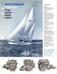
GENERATOR DISASSEMBLY<br />
The generator layout should be studied carefully before<br />
disassembly.<br />
1. Remove terminal box cover. Disconnect the wire leads<br />
from the generator. If necessary, disassemble the voltage<br />
regulator support (if the Automatic Voltage Regulator is<br />
. mounted in the terminal box) <strong>and</strong> the box complete.<br />
2. Disconnect the voltage regulator leads <strong>and</strong> the leads<br />
from the exciter stator F + <strong>and</strong> F - to the voltage<br />
regulator.<br />
3. Remove the fastening bolts to the generator <strong>and</strong><br />
disassemble the generator from the prime mover by<br />
disconnecting the adapter housing <strong>and</strong> the coupling<br />
disc from the flywheel.<br />
4. Remove the protective cover on the exciter side <strong>and</strong><br />
loosen the bolts on the bearing shield. remove it from<br />
the housing by pulling it back.<br />
FLYWHEEL AND BELL<br />
HOUSING ASSEMBLY<br />
(TYPICAL)<br />
COVER HEAD BOLTS<br />
5mm ALLEN HEAD<br />
(COVER REMOVAL BOLTS)<br />
(8mm X 1.25)<br />
EXCITER<br />
ROTOR<br />
COLISEUM GENERATOR<br />
-.&IY: WESTERBEKE<br />
Engines & Generators<br />
60<br />
5. Remove the rotor horizontally through the flange end of<br />
the generator.<br />
6. When the rotating rectifier is to be removed, the bearing<br />
should be pulled out first.<br />
NOTES: During the transport of the single bearing generator,<br />
the rotor of the generator should be fixed to the housing with<br />
the coupling disc on the Jlange.<br />
Closed type bearings are used on this series of generators.<br />
During the dismantling, be careful not to damage the<br />
protective cover rings.<br />
To prevent damage to the rotor <strong>and</strong> stator windings while<br />
removing the rotor, place cardboard between the packnges<br />
<strong>and</strong> remove the rotor by pulling it out gently.<br />
START MOTOR<br />
DRIVE<br />
DISC
METRIC CONVERSIONS.<br />
INCHES TO MILLIMETERS MILLIMETERS TO INCHES<br />
Inches mm Inches mm mm Inches mm Inches<br />
1 25.40 15 381.00 1 0.0394 15 0.5906<br />
2 50,80 20 50<strong>8.0</strong>0 2 0.0787 20 0.7874<br />
3 76.20 25 635.00 3 0.1181 25 0.9843<br />
4 101.60 30 762.00 4 0.1575 30 1.1811<br />
5 127.00 35 889.00 5 0.1969 35 1.3780<br />
10 254.00 40 1016.00 10 0.3937 40 1.5748<br />
10·MILLIMETERS = 1 CENTIMETER, 100 CENTIMETERS = 1 METER = 39.37 INCHES (3.3 FEET)<br />
INCHES TO METERS METERS TO INCHES<br />
Inches Meters Inches Meters Meters Inches Meters Inches<br />
1 0.0254 7 0.1778 0.1 3.937 0.7 27.559<br />
2 0.0508 8 0.2032 0.2 7.874 0.8 31.496<br />
3 0.0762 9 0.2286 0.3 11.811 0.9 35.433<br />
4 0.1016 10 0.2540 0.4 15.748 1.0 39.370<br />
5 0.1270 11 0.2794 0.5 19.685 1.1 43.307<br />
6 0.1524 12 0.3048 0.6 23.622 1.2 47.244<br />
TO CONVERT METERS TO CENTIMETERS, MOVE DECIMAL POINT TWO PLACES TO THE RIGHT<br />
YARDS TO METERS METERS TO YARDS<br />
Yards Meters Yards Meters Meters Yards Meters Yards<br />
1 0.91440 6 5.48640 1 1.09361 6 6.56168<br />
2 1.82880 7 6.40080 2 2.18723 7 7.65529<br />
3 2.74320 8 7.31520 3 3.28084 8 8.74891<br />
4 3.65760 9 8.22960 4 4.37445 9 9.84252<br />
5 4.57200 10 9.14400 5 5.46807 10 10.93614<br />
MOVE DECIMAL POINT FOR HIGHER VALUES - e.g. 6,000 METERS = 6,561.68 YARDS<br />
POUNDS TO KILOGRAMS KILOGRAMS TO POUNDS<br />
Ib kg Ib kg kg Ib kg Ib<br />
1 0.454 6 2.722 1 2.205 6 13.228<br />
2 0.907 7 3.175 2 4.409 7 15.432<br />
3 1.361 8 3.629 3 6.614 8 17.637<br />
4 1.814 9 4.082 4 8.818 9 19.842<br />
5 2.268 10 4.536 5 11.023 10 22.046<br />
GALLONS TO LITERS LITERS TO GALLONS<br />
Gallons Liters Gallons Liters Liters Gallons Liters Gallons<br />
1 3.79 10 37.86 1 0.26 60 15.66<br />
2 7.57 20 75.71 2 0.53 90 23.n<br />
3 11.36 30 113.57 5 1.32 120 31.32<br />
4 15.14 40 151.42 10 2.64 150 39.62<br />
5 18.93 50 189.28 20 5.28 180 47.54<br />
PINTS TO LITERS LITERS TO PINTS<br />
Pints Liters Pints Liters Liters Pints Liters Pints<br />
1 0.47 6 2.84 1 2.11 6 12.68<br />
2 0.95 7 3.31 2 4.23 7 14.79<br />
3 1.42 8 3.79 3 6.34 8 16.91<br />
4 1.89 9 4.26 4 8.45 9 19.02<br />
5 2.37 10 4.73 5 10.57 10 21.13<br />
TEMPERATURE<br />
32 40 50 60 70 75 85 95 105 140 175 212 of<br />
I I I I I I I I I I I I<br />
I I I I I I I I I I I I<br />
0 5 10 15 20 25 30 35 40 60 80 100 °C<br />
,.yo WESTERBEKE<br />
Engines & Generators<br />
66
STANDARD AND METRIC CONVERSION DATA<br />
LENGTH-DISTANCE<br />
Inches (in) x 25.4 = Millimeters (mm) x.0394 = Inches<br />
Feet (II) x .305 = Meters (m) x 3.281 = Feet<br />
Miles x 1.609 = Kilometers (km) x .0621 = Miles<br />
,.<br />
DISTANCE EQUIVALENTS<br />
1 Degree of Latilude = 60 Nm = 111.120 km<br />
1 Minute of Latitude = 1 Nm = 1.852 km<br />
VOLUME<br />
Cubic Inches (in') x 16.387 = Cubic Centimeters x .061 =in'<br />
Imperial Pints (IMP pt) x .568 = Liters (L) x 1.76 = IMP pt<br />
Imperial Quarts (IMP qt) x 1.137 = Liters (L) x.88 = IMP qt<br />
Imperial Gallons (IMP gal) x 4.546 = Liters (L) x .22 = IMP gal<br />
Imperial Quarts (IMP qt) x 1.201 = US Quarts (US qt) x .833 = IMP qt<br />
Imperial Gallons (IMP gal) x 1.201 = US Gallons (US gal) x .833 = IMP gal<br />
Fluid Ounces'x 29.573 = Milliliters x .034 = Ounces<br />
US Pints (US pt) x .473 = Liters(L) x 2.113 = Pints<br />
'US Quarts (US qt) x .946 = Liters (L) x 1.057 = Quarts<br />
US Gallons (US gal) x 3.785 = Liters (L) x .264 = Gallons<br />
MASS-WEIGHT<br />
Ounces (oz) x 28.35 = Grams (g) x .035 = Ounces<br />
Pounds (Ib) x .454 = Kilograms (kg) x 2.205 = Pounds<br />
PRESSURE<br />
Pounds Per Sq In (psi) x 6.895 = Kilopascals (kPa) x .145 = psi<br />
Inches of Mercury (Hg) x .4912 = psi x 2.036 = Hg<br />
Inches of Mercury (Hg) x 3.377 = Kiiopascals'(kPa) x .2961 = Hg<br />
Inches of Water (H20) x .07355 = Inches of Mercury x 13.783 = H20<br />
Inches of Water (HID) x .03613 = psi x 27.684 = H20<br />
Inches of Water (H20) x .248 = Kilopascals (kPa) x 4.026 = H20<br />
TORQUE<br />
Pounds-Force Inches (In-Ib) x .113 = Newton Meters (Nm) x 8.85 =in-Ib<br />
Pounds-Force Feet (II-Ib) x 1.356 = Newton Meters (Nm) x .738 = II-Ib<br />
VELOCITY<br />
- Miles Per Hour (MPH) x 1.609 = Kilometers Per Hour (KPH) x .621 = MPH<br />
POWER<br />
Horsepower (Hp) x .745 = Kilowatts (Kw) x 1.34 = MPH<br />
FUEL CONSUMPTION<br />
Miles Per Hour IMP (MPG) x .354 = Kilometers Per Liter (Km/L)<br />
Kilometers Per Liter (Km/L) x 2.352 = IMP MPG<br />
Miles Per Gallons US (MPG) x .425 = Kilometers Per Liter (Km/L)<br />
Kilometers Per Liler (Km/L) x 2.352 = US MPG<br />
TEMPERATURE<br />
Degree Fahrenheit (OF) = (OC X 1.8) + 32<br />
Degree Celsius ("C) = (OF - 32) x .56<br />
UQUIO WEIGHTS<br />
Diesel 011 = 1 US gallon = 7.13 Ibs<br />
Fresh Water = 1 US gallon = 8.33 Ibs<br />
Gasoline = 1 US gallon = 6.1 Ibs<br />
Salt Water = 1 US gallon = 8.56 Ibs<br />
..v: WESTERSEKE<br />
Eng/nIlS & Generators<br />
67
CRANKSHAFT OIL SEAL INSTALLER<br />
For installing the front oil seal<br />
MD 998305<br />
SPECIAL TOOLS<br />
NOTE: These special tools are available from your local Mitsubishi Automotive Dealer.<br />
CRANKSHAFT REAR OIL SEAL INSTALLER<br />
For installing the rear oil seal. '---.<br />
MD 998011<br />
PUSH ROD AND PIN SET GUIDE<br />
Used to pUll-out <strong>and</strong> press in<br />
the piston pin,<br />
MD 999584<br />
PIN<br />
For supporting the sprocket when<br />
the camshaft sprocket is loosened<br />
or tightened,<br />
MD 998715<br />
END YOKE HOLDER<br />
For supporting the sprocket when<br />
the camshaft sprocket is loosened<br />
or lightened.<br />
MD 990767<br />
VALVE STEM SEAL INSTALLER<br />
MD998760<br />
OIL PAN GASKET CUTTER<br />
For removing the oil pan to<br />
break the oil pan seal.<br />
MD 998727<br />
VALVE SPRING COMPRESSOR<br />
MD 998772<br />
PISTON PIN SET TOOL<br />
For press tiffing piston pins<br />
MD 998780<br />
GUIDE 0<br />
For removing <strong>and</strong> pressing<br />
piston pins<br />
MD 991659<br />
VALVE SPRING COMPRESSOR<br />
For removing <strong>and</strong> installing the<br />
valve springs.<br />
,,!D 998735<br />
Engines & Generators<br />
68
Alternator Specifications ................... .49<br />
Alternator Troubleshooting .................. 31<br />
Alternator-Disassembly <strong>and</strong> Testing ........ .43-49<br />
Assembly & Disassembly Procedures ........... 8<br />
Bearing Cap ............................. 27<br />
Bearing-Connecting Rod .................... 25<br />
Belt Timing .............................. 10<br />
Bolt Tightening Methods ..................... 9<br />
Bolts-Cylinder Head ....................... 19<br />
Boring Cylinders .......................... 26<br />
Camshaft . . . . . . . . . . . . . . . . . . . . . . . . . ....... 15<br />
Carburetor . . . . . . . . . . . . . . . ............... .41<br />
Coliseum Generator ....................... 52<br />
Compression Testing ....................... 44<br />
Connecting Rod .......................... 24<br />
Connecting Rod Cap Nut ................... 25<br />
Control Panel-Generator ................... .55<br />
Coolant Circulating Pump . . . . ............... 28<br />
Crankshaft ............................... 24<br />
Crankshaft Bearings ...................... 25a<br />
Crankshaft Pin . . . . . . . . . . . ................. 23<br />
Cylinder Block .......................... .26<br />
Cylinder Head . . . . . . . . . . . . . . . . ............ 16<br />
Cylinder Head Bolts ....................... 19 .<br />
Disassembly & Assembly Procedures ........... 8<br />
Distributor ............................... 29<br />
Drive Belt Adjustments .................... .40<br />
Engine Disassembly ....................... 13<br />
Engine Specifications ..... .................. 2<br />
Exterior Assemblies & Disassemblies .......... 13<br />
Front Oil Seal ............................ 21<br />
Generator Internal Wiring ................... 56<br />
Generator Schematic ....................... 33<br />
Generator Troubleshooting .................. 54<br />
Generator Wiring Diagram .................. 34<br />
Generator-Coliseum ....................... 52<br />
Generator-Exploded View ................... 60<br />
Governor ............................... .42<br />
Igniter-Testing ........................... .30<br />
Ignition Tuning .......................... .39<br />
Metric Conversions ..................... 65-67<br />
Oil Pan ................................. 20<br />
Oil Pressure .............................. 38<br />
Oil Pump ................................ 20<br />
Oil Seal-Front ............................ 21<br />
Oil Seal-Rear ............................ 27<br />
INDEX<br />
Piston Rings .....,...................... .22<br />
Pump-Coolant . . . . . . . . . . . . . . . . . . . . . . . . . . . .28<br />
Pump-Oil ............................... 20<br />
Rear Oil Seal ............................. 27<br />
Regulator-Voltage ......................... 56<br />
Rings-Piston ...................... ...... .22<br />
Rocker Arms ............................ .15<br />
Rocker Cover ....................... ..... 19<br />
Rod-Connecting ......................... .24<br />
Schematic-Generators ..................... .33<br />
Sealants <strong>and</strong> Lubricants ..................... 64<br />
Service Specifications ...................... 61<br />
Shutdown Switches ....................... 6-7<br />
Spark Plugs ............................. .40<br />
Special Tools ............................. 68<br />
Specifications-Alternator ................... .49<br />
Specifications-Engine ...................... .2<br />
Specifications-Torque .................... 63-66<br />
St<strong>and</strong>ards <strong>and</strong> Limits ....................... 61<br />
Starter Motor-Disassembly .................. 51<br />
Starter Motor-Testing ...................... 50<br />
Switches-Shutdown ....................... 6-7<br />
Testing Oil Pressure ...................... .38<br />
Testing the Igniter . . . . . . . . . . . . . . . . . . ...... .30<br />
Timing Belt . . . . . . . . . . . . . . . . . . . . . . . . . ..... 10<br />
Tools-Special ............................ 68<br />
Torque Specifications .................... 63-66<br />
Troubleshooting Guide-Engine ............... .4<br />
Troubleshooting-Alternator .................. 31<br />
Troubleshooting-Generator ................. .53<br />
Valve Clearance ......................... .39<br />
Valves, Valve Springs <strong>and</strong> Guides ............ .17<br />
Voltage Regulator ......................... 56<br />
Wiring Diagram-Generator .................. 34<br />
Wiring Diagram-Remote Panel .............. .35<br />
Wiring Diagram-Remote Start ............ .36-37<br />
Engines & Genera/ors<br />
69