Design, Manufacturing, and Testing of an Improved Watertight Door ...
Design, Manufacturing, and Testing of an Improved Watertight Door ...
Design, Manufacturing, and Testing of an Improved Watertight Door ...

Create successful ePaper yourself
Turn your PDF publications into a flip-book with our unique Google optimized e-Paper software.
<strong>Design</strong>, <strong>M<strong>an</strong>ufacturing</strong>, <strong><strong>an</strong>d</strong> <strong>Testing</strong> <strong>of</strong> <strong>an</strong> <strong>Improved</strong> <strong>Watertight</strong> <strong>Door</strong><br />
94 &2010 #4<br />
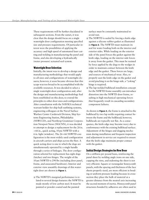
These requirements will be further elucidated in<br />
subsequent sections. From the outset, it was<br />
clear that the design should focus on a single<br />
watertight door configuration meeting specified<br />
size <strong><strong>an</strong>d</strong> pressure requirements. Of particular interest<br />
were the possibilities <strong>of</strong> applying the<br />
accuracy <strong><strong>an</strong>d</strong> high speed <strong>of</strong> automated laser cutting<br />
<strong><strong>an</strong>d</strong> welding in m<strong>an</strong>ufacturing the p<strong>an</strong>el <strong><strong>an</strong>d</strong><br />
frame, <strong><strong>an</strong>d</strong> also developing a hydraulically<br />
(water pressure) actuated seal system.<br />
<strong>Watertight</strong> <strong>Door</strong> Selection<br />
Initially, the intent was to develop a design <strong><strong>an</strong>d</strong><br />
m<strong>an</strong>ufacturing methodology that would apply<br />
to all sizes <strong><strong>an</strong>d</strong> configurations <strong>of</strong> watertight closures;<br />
however, it soon became obvious that this<br />
scope was too broad to be accomplished with the<br />
available resources. It was decided to select a<br />
single watertight door configuration <strong><strong>an</strong>d</strong>, after<br />
the design <strong><strong>an</strong>d</strong> m<strong>an</strong>ufacturing methodology had<br />
been established on this door, to extend the<br />
principles to other door sizes <strong><strong>an</strong>d</strong> configurations.<br />
After consultation with the NAVSEA technical<br />
warr<strong>an</strong>t holder for ship hull outfitting systems,<br />
engineering colleagues at the Naval Surface<br />
Warfare Center Carderock Division, Ship Systems<br />
Engineering Station, Philadelphia<br />
(NSWCCD), <strong><strong>an</strong>d</strong> Northrop Grumm<strong>an</strong> Corporation<br />
Newport News (NGCNN), it was decided<br />
to attempt to design a replacement for the 26 in.<br />
66 in., quick acting, 10 psi NSWTD with a<br />
6 in. light (window). The 26 66 NSWTD configuration<br />
is the most widely used configuration<br />
in aircraft carriers <strong><strong>an</strong>d</strong> ships across the fleet. A<br />
quick acting door is one in which the dogs are<br />
simult<strong>an</strong>eously operated by a single h<strong><strong>an</strong>d</strong>le<br />
through a series <strong>of</strong> linkages. The door configuration<br />
selected for replacement has eight dogs<br />
(latches) <strong><strong>an</strong>d</strong> two hinges. The weight <strong>of</strong> the<br />
10 psi NSWTD is 290 lbs (including door p<strong>an</strong>el,<br />
frame, <strong><strong>an</strong>d</strong> associated hardware). Interior <strong><strong>an</strong>d</strong><br />
exterior view assembly drawings <strong>of</strong> this watertight<br />
door are shown in Figure 1.<br />
& The NSWTD’s marginal perform<strong>an</strong>ce is related<br />
to several design features: the NSWTD is<br />
made mostly <strong>of</strong> low carbon steel. It must be<br />
painted or powder coated <strong><strong>an</strong>d</strong> the painted<br />
surface must be const<strong>an</strong>tly maintained to<br />
avoid rust.<br />
& The NSWTD is sealed by forcing a knife edge<br />
against a silicone rubber gasket as illustrated<br />
in Figure 2. The NSWTD must maintain its<br />
seal for water loading both on the interior <strong><strong>an</strong>d</strong><br />
exterior sides. While loading on the exterior<br />
side <strong>of</strong> the p<strong>an</strong>el forces the gasket against the<br />
knife edge, loading on the interior side forces<br />
it away from the gasket. This must be resisted<br />
by force applied by the dogs to the wedges in<br />
order to maintain contact between the knife<br />
edge <strong><strong>an</strong>d</strong> the gasket. These forces are large,<br />
<strong><strong>an</strong>d</strong> sources <strong>of</strong> mech<strong>an</strong>ical wear. Also, to<br />
properly seat the knife edge on the gasket <strong><strong>an</strong>d</strong><br />
avoid pinching it on the hinge side, a ‘‘yoking’’<br />
hinge is required.<br />
& The lap-welded bulkhead installation concept<br />
for the NSWTD frame assembly c<strong>an</strong> introduce<br />
distortion into the NSWTD door frame, resulting<br />
in high mech<strong>an</strong>ical operating forces<br />
that frequently result in cascading secondary<br />
component failures.<br />
As shown in Figure 3, the frame is attached to the<br />
bulkhead by two lap welds requiring contact between<br />
the frame <strong><strong>an</strong>d</strong> the bulkhead; however,<br />
bulkheads are typically not flat. As a consequence,<br />
the knife edge may become wavy due to<br />
conform<strong>an</strong>ce with the existing bulkhead surface.<br />
Adjustment <strong>of</strong> the hinges <strong><strong>an</strong>d</strong> dogging mech<strong>an</strong>ism<br />
during installation <strong><strong>an</strong>d</strong> frequent inspection<br />
<strong><strong>an</strong>d</strong> adjustment in-service are required to ensure<br />
that the knife edge maintains proper contact<br />
with the gasket.<br />
Initial <strong>Design</strong> Strategies forNew<strong>Door</strong><br />
On a stiffness per pound basis, reinforcing the<br />
p<strong>an</strong>el sheet by welding <strong>an</strong>gle irons on one side,<br />
cupping the rims, <strong><strong>an</strong>d</strong> indenting the sheet is not<br />
very efficient. Square or rect<strong>an</strong>gular honeycomb<br />
p<strong>an</strong>els, with the spacing <strong><strong>an</strong>d</strong> thickness <strong>of</strong> the face<br />
sheets properly sized, are more efficient in bending<br />
or uniform pressure loading because in crosssection<br />
they place the bulk <strong>of</strong> material at a<br />
greater dist<strong>an</strong>ce from the neutral axis increasing<br />
the second moment <strong>of</strong> inertia. Honeycomb p<strong>an</strong>el<br />
structures bonded by adhesives are <strong>of</strong>ten used in<br />
NAVAL ENGINEERS JOURNAL