Design, Manufacturing, and Testing of an Improved Watertight Door ...
Design, Manufacturing, and Testing of an Improved Watertight Door ...
Design, Manufacturing, and Testing of an Improved Watertight Door ...

You also want an ePaper? Increase the reach of your titles
YUMPU automatically turns print PDFs into web optimized ePapers that Google loves.
<strong>Design</strong>, <strong>M<strong>an</strong>ufacturing</strong>, <strong><strong>an</strong>d</strong> <strong>Testing</strong><br />
<strong>of</strong> <strong>an</strong> <strong>Improved</strong> <strong>Watertight</strong> <strong>Door</strong> for<br />
Surface Ships<br />
& Stephen M. Copley, Edward W. Reutzel, Terri A. Merdes, <strong><strong>an</strong>d</strong> Dennis B. Wess<br />
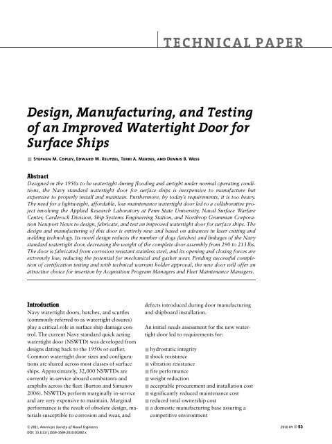
Abstract<br />
<strong>Design</strong>ed in the 1950s to be watertight during flooding <strong><strong>an</strong>d</strong> airtight under normal operating conditions,<br />
the Navy st<strong><strong>an</strong>d</strong>ard watertight door for surface ships is inexpensive to m<strong>an</strong>ufacture but<br />
expensive to properly install <strong><strong>an</strong>d</strong> maintain. Furthermore, by today’s requirements, it is too heavy.<br />
The need for a lightweight, affordable, low mainten<strong>an</strong>ce watertight door led to a collaborative project<br />
involving the Applied Research Laboratory at Penn State University, Naval Surface Warfare<br />
Center, Carderock Division, Ship Systems Engineering Station, <strong><strong>an</strong>d</strong> Northrop Grumm<strong>an</strong> Corporation<br />
Newport News to design, fabricate, <strong><strong>an</strong>d</strong> test <strong>an</strong> improved watertight door for surface ships. The<br />
design <strong><strong>an</strong>d</strong> m<strong>an</strong>ufacturing <strong>of</strong> this door is entirely new <strong><strong>an</strong>d</strong> based on adv<strong>an</strong>ces in laser cutting <strong><strong>an</strong>d</strong><br />
welding technology. Its novel design reduces the number <strong>of</strong> dogs (latches) <strong><strong>an</strong>d</strong> linkages <strong>of</strong> the Navy<br />
st<strong><strong>an</strong>d</strong>ard watertight door, decreasing the weight <strong>of</strong> the complete door assembly from 290 to 213 lbs.<br />
The door is fabricated from corrosion resist<strong>an</strong>t stainless steel, <strong><strong>an</strong>d</strong> its opening <strong><strong>an</strong>d</strong> closing forces are<br />
extremely low, reducing the potential for mech<strong>an</strong>ical <strong><strong>an</strong>d</strong> gasket wear. Pending successful completion<br />
<strong>of</strong> certification testing <strong><strong>an</strong>d</strong> with technical warr<strong>an</strong>t holder approval, the new door will <strong>of</strong>fer <strong>an</strong><br />
attractive choice for insertion by Acquisition Program M<strong>an</strong>agers <strong><strong>an</strong>d</strong> Fleet Mainten<strong>an</strong>ce M<strong>an</strong>agers.<br />
Introduction<br />
Navy watertight doors, hatches, <strong><strong>an</strong>d</strong> scuttles<br />
(commonly referred to as watertight closures)<br />
play a critical role in surface ship damage control.<br />
The current Navy st<strong><strong>an</strong>d</strong>ard quick acting<br />
watertight door (NSWTD) was developed from<br />
designs dating back to the 1950s or earlier.<br />
Common watertight door sizes <strong><strong>an</strong>d</strong> configurations<br />
are shared across most classes <strong>of</strong> surface<br />
ships. Approximately, 32,000 NSWTDs are<br />
currently in-service aboard combat<strong>an</strong>ts <strong><strong>an</strong>d</strong><br />
amphibs across the fleet (Burton <strong><strong>an</strong>d</strong> Simunov<br />
2006). NSWTDs perform marginally in-service<br />
<strong><strong>an</strong>d</strong> are very expensive to maintain. Marginal<br />
perform<strong>an</strong>ce is the result <strong>of</strong> obsolete design, materials<br />
susceptible to corrosion <strong><strong>an</strong>d</strong> wear, <strong><strong>an</strong>d</strong><br />
& 2011, Americ<strong>an</strong> Society <strong>of</strong> Naval Engineers<br />
DOI: 10.1111/j.1559-3584.2010.00282.x<br />
TECHNICAL PAPER<br />
defects introduced during door m<strong>an</strong>ufacturing<br />
<strong><strong>an</strong>d</strong> shipboard installation.<br />
An initial needs assessment for the new watertight<br />
door led to requirements for:<br />
& hydrostatic integrity<br />
& shock resist<strong>an</strong>ce<br />
& vibration resist<strong>an</strong>ce<br />
& fire perform<strong>an</strong>ce<br />
& weight reduction<br />
& acceptable procurement <strong><strong>an</strong>d</strong> installation cost<br />
& signific<strong>an</strong>tly reduced mainten<strong>an</strong>ce cost<br />
& reduced total ownership cost<br />
& a domestic m<strong>an</strong>ufacturing base assuring a<br />
competitive environment<br />
2010 #4 & 93
<strong>Design</strong>, <strong>M<strong>an</strong>ufacturing</strong>, <strong><strong>an</strong>d</strong> <strong>Testing</strong> <strong>of</strong> <strong>an</strong> <strong>Improved</strong> <strong>Watertight</strong> <strong>Door</strong><br />
94 &2010 #4<br />
These requirements will be further elucidated in<br />
subsequent sections. From the outset, it was<br />
clear that the design should focus on a single<br />
watertight door configuration meeting specified<br />
size <strong><strong>an</strong>d</strong> pressure requirements. Of particular interest<br />
were the possibilities <strong>of</strong> applying the<br />
accuracy <strong><strong>an</strong>d</strong> high speed <strong>of</strong> automated laser cutting<br />
<strong><strong>an</strong>d</strong> welding in m<strong>an</strong>ufacturing the p<strong>an</strong>el <strong><strong>an</strong>d</strong><br />
frame, <strong><strong>an</strong>d</strong> also developing a hydraulically<br />
(water pressure) actuated seal system.<br />
<strong>Watertight</strong> <strong>Door</strong> Selection<br />
Initially, the intent was to develop a design <strong><strong>an</strong>d</strong><br />
m<strong>an</strong>ufacturing methodology that would apply<br />
to all sizes <strong><strong>an</strong>d</strong> configurations <strong>of</strong> watertight closures;<br />
however, it soon became obvious that this<br />
scope was too broad to be accomplished with the<br />
available resources. It was decided to select a<br />
single watertight door configuration <strong><strong>an</strong>d</strong>, after<br />
the design <strong><strong>an</strong>d</strong> m<strong>an</strong>ufacturing methodology had<br />
been established on this door, to extend the<br />
principles to other door sizes <strong><strong>an</strong>d</strong> configurations.<br />
After consultation with the NAVSEA technical<br />
warr<strong>an</strong>t holder for ship hull outfitting systems,<br />
engineering colleagues at the Naval Surface<br />
Warfare Center Carderock Division, Ship Systems<br />
Engineering Station, Philadelphia<br />
(NSWCCD), <strong><strong>an</strong>d</strong> Northrop Grumm<strong>an</strong> Corporation<br />
Newport News (NGCNN), it was decided<br />
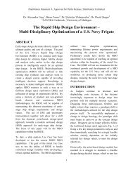
to attempt to design a replacement for the 26 in.<br />
66 in., quick acting, 10 psi NSWTD with a<br />
6 in. light (window). The 26 66 NSWTD configuration<br />
is the most widely used configuration<br />
in aircraft carriers <strong><strong>an</strong>d</strong> ships across the fleet. A<br />
quick acting door is one in which the dogs are<br />
simult<strong>an</strong>eously operated by a single h<strong><strong>an</strong>d</strong>le<br />
through a series <strong>of</strong> linkages. The door configuration<br />
selected for replacement has eight dogs<br />
(latches) <strong><strong>an</strong>d</strong> two hinges. The weight <strong>of</strong> the<br />
10 psi NSWTD is 290 lbs (including door p<strong>an</strong>el,<br />
frame, <strong><strong>an</strong>d</strong> associated hardware). Interior <strong><strong>an</strong>d</strong><br />
exterior view assembly drawings <strong>of</strong> this watertight<br />
door are shown in Figure 1.<br />
& The NSWTD’s marginal perform<strong>an</strong>ce is related<br />
to several design features: the NSWTD is<br />
made mostly <strong>of</strong> low carbon steel. It must be<br />
painted or powder coated <strong><strong>an</strong>d</strong> the painted<br />
surface must be const<strong>an</strong>tly maintained to<br />
avoid rust.<br />
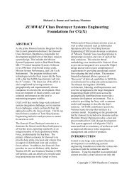
& The NSWTD is sealed by forcing a knife edge<br />
against a silicone rubber gasket as illustrated<br />
in Figure 2. The NSWTD must maintain its<br />
seal for water loading both on the interior <strong><strong>an</strong>d</strong><br />
exterior sides. While loading on the exterior<br />
side <strong>of</strong> the p<strong>an</strong>el forces the gasket against the<br />
knife edge, loading on the interior side forces<br />
it away from the gasket. This must be resisted<br />
by force applied by the dogs to the wedges in<br />
order to maintain contact between the knife<br />
edge <strong><strong>an</strong>d</strong> the gasket. These forces are large,<br />
<strong><strong>an</strong>d</strong> sources <strong>of</strong> mech<strong>an</strong>ical wear. Also, to<br />
properly seat the knife edge on the gasket <strong><strong>an</strong>d</strong><br />
avoid pinching it on the hinge side, a ‘‘yoking’’<br />
hinge is required.<br />
& The lap-welded bulkhead installation concept<br />
for the NSWTD frame assembly c<strong>an</strong> introduce<br />
distortion into the NSWTD door frame, resulting<br />
in high mech<strong>an</strong>ical operating forces<br />
that frequently result in cascading secondary<br />
component failures.<br />
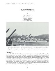
As shown in Figure 3, the frame is attached to the<br />
bulkhead by two lap welds requiring contact between<br />
the frame <strong><strong>an</strong>d</strong> the bulkhead; however,<br />
bulkheads are typically not flat. As a consequence,<br />
the knife edge may become wavy due to<br />
conform<strong>an</strong>ce with the existing bulkhead surface.<br />
Adjustment <strong>of</strong> the hinges <strong><strong>an</strong>d</strong> dogging mech<strong>an</strong>ism<br />
during installation <strong><strong>an</strong>d</strong> frequent inspection<br />
<strong><strong>an</strong>d</strong> adjustment in-service are required to ensure<br />
that the knife edge maintains proper contact<br />
with the gasket.<br />
Initial <strong>Design</strong> Strategies forNew<strong>Door</strong><br />
On a stiffness per pound basis, reinforcing the<br />
p<strong>an</strong>el sheet by welding <strong>an</strong>gle irons on one side,<br />
cupping the rims, <strong><strong>an</strong>d</strong> indenting the sheet is not<br />
very efficient. Square or rect<strong>an</strong>gular honeycomb<br />
p<strong>an</strong>els, with the spacing <strong><strong>an</strong>d</strong> thickness <strong>of</strong> the face<br />
sheets properly sized, are more efficient in bending<br />
or uniform pressure loading because in crosssection<br />
they place the bulk <strong>of</strong> material at a<br />
greater dist<strong>an</strong>ce from the neutral axis increasing<br />
the second moment <strong>of</strong> inertia. Honeycomb p<strong>an</strong>el<br />
structures bonded by adhesives are <strong>of</strong>ten used in<br />
NAVAL ENGINEERS JOURNAL
Figure 1: Navy St<strong><strong>an</strong>d</strong>ard <strong>Watertight</strong> <strong>Door</strong> (26 in. 66 in., Quick Acting, 10 psi <strong>Door</strong> with Window): (a) Interior Side <strong><strong>an</strong>d</strong> (b) Exterior Side (NAVSEA 1987)<br />
lightweight structures. Metallic honeycomb<br />
p<strong>an</strong>els have been produced by brazing metallic<br />
alloy face sheets to the honeycomb. Using brazes<br />
to join metallic stiffeners to face sheets for use in<br />
a sea environment is undesirable: the chemical<br />
dissimilarity <strong>of</strong> the braze alloys to the metallic<br />
honeycomb p<strong>an</strong>el creates a high risk <strong>of</strong> galv<strong>an</strong>ic<br />
corrosion.<br />
It was recognized early in this project that laser<br />
welding <strong><strong>an</strong>d</strong> cutting could potentially provide <strong>an</strong><br />
entirely new approach for fabricating metallic<br />
alloy honeycomb p<strong>an</strong>els <strong><strong>an</strong>d</strong> frames for the new<br />
watertight door. Laser cutting is fast <strong><strong>an</strong>d</strong> very<br />
accurate. Face sheets could be autogenously<br />
welded to the honeycomb, i.e., welded without<br />
filler metal, at high speeds. Laser cut <strong><strong>an</strong>d</strong> welded<br />
p<strong>an</strong>els could be fabricated from stainless steel<br />
greatly reducing the risk <strong>of</strong> corrosion. A number<br />
<strong>of</strong> domestic, commercial job shops were identi-<br />
fied that were capable <strong>of</strong> laser cutting <strong><strong>an</strong>d</strong><br />
welding the new watertight door. The application<br />
<strong>of</strong> laser technology to the m<strong>an</strong>ufacturing <strong>of</strong><br />
stainless steel watertight doors was identified as<br />
<strong>an</strong> import<strong>an</strong>t design strategy for the new door.<br />
Figure 2: Dog Detail<br />
(NAVSEA 1987)<br />
NAVAL ENGINEERS JOURNAL 2010 #4 &95
<strong>Design</strong>, <strong>M<strong>an</strong>ufacturing</strong>, <strong><strong>an</strong>d</strong> <strong>Testing</strong> <strong>of</strong> <strong>an</strong> <strong>Improved</strong> <strong>Watertight</strong> <strong>Door</strong><br />
Figure 3: Edge Section<br />
<strong>of</strong> NSWTD Seal<br />
System Showing the<br />
Frame Lap Welded to<br />
the Bulkhead with Its<br />
Knife Edge Contacting<br />
the Gasket<br />
Figure 4: Hydraulically<br />
Actuated Seal<br />
<strong><strong>an</strong>d</strong> Plug-In-Hole Installation<br />
Concepts<br />
96 & 2010 #4<br />
PANEL<br />
FRAME<br />
WITH<br />
KNIFE<br />
EDGE<br />
A second import<strong>an</strong>t design strategy was to replace<br />
the dogs, wedges, knife edge, <strong><strong>an</strong>d</strong><br />
compression gasket seal system <strong>of</strong> the NSWTD<br />
with a novel hydraulically actuated seal system.<br />
The initial concept is illustrated in Figure 4.<br />
Flooding the door on one side forces the hollow<br />
cylindrical gasket against the gap on the other<br />
side plugging it <strong><strong>an</strong>d</strong> vice versa. Unfortunately,<br />
this simple concept did not work due to the large<br />
dimensional ch<strong>an</strong>ges in the gasket cavity when<br />
the door was loaded. Also, lab testing <strong>of</strong> early<br />
prototypes <strong>of</strong> the hollow oval seal configuration<br />
revealed that unacceptably high compressive<br />
forces were required to initially seat the seal to<br />
ensure watertight perform<strong>an</strong>ce. This finding<br />
clarified the desirability <strong>of</strong> a seal design that did<br />
not require high initial compressive forces. In the<br />
end, the development <strong>of</strong> a hydraulically actuated,<br />
leak-free seal system became the most<br />
challenging design aspect <strong>of</strong> the project.<br />
Also illustrated in Figure 4 is the third import<strong>an</strong>t<br />
design strategy, which will be referred to as the<br />
PANEL<br />
GASKET<br />
GASKET<br />
LAP WELDS<br />
BULKHEAD<br />
FRAME BULKHEAD<br />
FILLET WELDS<br />
plug-in-hole frame. This strategy eliminates the<br />
influence <strong>of</strong> bulkhead waviness on the seal system.<br />
The plug-in-hole frame is designed to slide<br />
inside the hole cut in the bulkhead. It is attached<br />
to the bulkhead by two fillet welds. This improves<br />
upon the NSWTD design in which the<br />
frame is clamped <strong><strong>an</strong>d</strong> lap welded to the bulkhead.<br />
Lap welding the frame to the bulkhead<br />
causes the frame to conform to <strong>an</strong>y ‘‘waviness’’<br />
or ‘‘out-<strong>of</strong>-pl<strong>an</strong>e’’ condition <strong>of</strong> the existing<br />
bulkhead.<br />
In what follows, each <strong>of</strong> these strategies will be<br />
discussed in greater detail.<br />
LASER CUT AND WELDED DOOR PANEL AND<br />
FRAME<br />
At the heart <strong>of</strong> the new watertight door design is<br />
a laser cut <strong><strong>an</strong>d</strong> welded p<strong>an</strong>el structure called<br />
LASCELL (patent pending). It c<strong>an</strong> be described<br />
as a rect<strong>an</strong>gular (including square) honeycomb<br />
<strong>of</strong> laser cut metallic stiffeners, mech<strong>an</strong>ically interlocked,<br />
joined to laser cut face sheets by<br />
autogenous welds through the face sheets into<br />
the stiffeners, as illustrated in Figures 5 <strong><strong>an</strong>d</strong> 7.<br />
It soon became clear that cutting the stiffeners<br />
<strong><strong>an</strong>d</strong> face sheets with a laser was straightforward<br />
whereas welding such a structure was to be a<br />
challenge. Although it was possible to spot weld<br />
the face sheets to the stiffeners without distortion,<br />
even one continuous weld <strong>of</strong> face sheet to<br />
stiffener caused the p<strong>an</strong>el to bend in fabrication<br />
<strong>of</strong> early prototypes. Multiple parallel continuous<br />
welds caused the p<strong>an</strong>el to form a cylindrical<br />
shape with the cylinder axis lying parallel to the<br />
welds.<br />
The origin <strong>of</strong> the observed distortion c<strong>an</strong> be explained<br />
as follows. When the face sheet was<br />
welded to the stiffener, the alloy melted locally<br />
<strong><strong>an</strong>d</strong> then resolidified as the laser beam moved<br />
past. As it resolidified, very hot melt at the weld<br />
was surrounded by unmelted solid that was<br />
much cooler because <strong>of</strong> the high speed <strong>of</strong> the laser<br />
beam. The resolidified melt, which was much<br />
hotter th<strong>an</strong> the surrounding solid, shr<strong>an</strong>k more<br />
due to thermal contraction upon cooling, result-<br />
NAVAL ENGINEERS JOURNAL
ing in plastic deformation that caused the observed<br />
distortion.<br />
To fabricate the first LASCELL p<strong>an</strong>el structure,<br />
the following procedure was developed. Laser<br />
cut stiffeners were assembled using a position<br />
fixture (<strong>an</strong> aluminum plate with <strong>an</strong> orthogonal<br />
grid <strong>of</strong> milled slots) to form the mech<strong>an</strong>ically interlocked<br />
rect<strong>an</strong>gular honeycomb. A face sheet<br />
was placed on the stiffeners <strong><strong>an</strong>d</strong> held in place by<br />
restraining bars, see Figure 6.<br />
Laser spot welds, one inch apart, were made<br />
through the face sheet joining it to a parallel set<br />
<strong>of</strong> stiffeners. The structure was then rotated by<br />
901 about <strong>an</strong> axis perpendicular to the face<br />
sheet, <strong><strong>an</strong>d</strong> a similar set <strong>of</strong> spot welds was made<br />
joining the face sheet to the second parallel set <strong>of</strong><br />
stiffeners, which were perpendicular to the first<br />
set. The p<strong>an</strong>el was then removed from the positioning<br />
fixture, turned over, <strong><strong>an</strong>d</strong> the process was<br />
repeated. In both the spot welding <strong><strong>an</strong>d</strong> the continuous<br />
welding steps to follow, welding started<br />
at the innermost stiffener(s) <strong><strong>an</strong>d</strong> progressed toward<br />
the face edges. No distortion <strong>of</strong> the p<strong>an</strong>el<br />
was observed after spot welding the face sheets<br />
to the stiffeners.<br />
With the spot-welded p<strong>an</strong>el restrained by the restraining<br />
bars as illustrated in Figure 6, one face<br />
sheet was then continuously autogenously laser<br />
welded to a parallel set <strong>of</strong> stiffeners. After this<br />
step, the p<strong>an</strong>el was released from the restraining<br />
bars. When the bars were removed, the tension<br />
stresses in the face sheet were partially relaxed<br />
by the distortion; however, this distortion caused<br />
residual tension stresses to develop in the face<br />
sheet on the opposite side <strong>of</strong> the p<strong>an</strong>el.<br />
In order to make a flat structure, the p<strong>an</strong>el was<br />
then turned over <strong><strong>an</strong>d</strong> elastically deformed by the<br />
fixtures so that it was again completely flat. It<br />
was then continuously laser welded to the same<br />
set <strong>of</strong> stiffeners on their opposite edge. Flattening<br />
the p<strong>an</strong>el was critical. If the p<strong>an</strong>el was not<br />
completely flat before the face sheet on the opposite<br />
side <strong>of</strong> the p<strong>an</strong>el was welded, the residual<br />
stresses introduced by continuously welding the<br />
first side would not be bal<strong>an</strong>ced by the residual<br />
stresses resulting from welding the second side,<br />
<strong><strong>an</strong>d</strong> the p<strong>an</strong>el would still be distorted to <strong>an</strong> unacceptable<br />
degree.<br />
The p<strong>an</strong>el was then rotated 901 in the x–y pl<strong>an</strong>e<br />
(see Figure 5), restrained by the fixtures, <strong><strong>an</strong>d</strong> the<br />
continuous welding process was repeated on opposite<br />
sides. If welding was carried out in<br />
accord<strong>an</strong>ce with this procedure, it was found<br />
that a completely flat p<strong>an</strong>el was produced.<br />
Figure 7 shows a stainless steel 1 ft 1 ft square<br />
LASCELL p<strong>an</strong>el (Alloy 316). The stiffeners were<br />
cut with a carbon dioxide laser from sheet<br />
0.120 in. thick at a speed <strong>of</strong> 50 in./min using<br />
2000 W beam power. A high-velocity N2 gas jet<br />
y<br />
x<br />
Figure 5: LASCELL<br />
Structure<br />
Figure 6: Positioning<br />
Fixture <strong><strong>an</strong>d</strong><br />
Restraining Bars<br />
NAVAL ENGINEERS JOURNAL 2010 #4 & 97
<strong>Design</strong>, <strong>M<strong>an</strong>ufacturing</strong>, <strong><strong>an</strong>d</strong> <strong>Testing</strong> <strong>of</strong> <strong>an</strong> <strong>Improved</strong> <strong>Watertight</strong> <strong>Door</strong><br />
Figure 7: Stainless<br />
Steel LASCELL P<strong>an</strong>el<br />
(Inset Shows Autogenous<br />
Weld, White<br />
Dots Added to Emphasize<br />
Weld<br />
Boundary)<br />
Figure 8: New <strong>Watertight</strong><br />
<strong>Door</strong> with<br />
Strong Backs (Arrows)<br />
Used to Restrain<br />
Frame during Welding<br />
to Bulkhead<br />
98 & 2010 #4<br />
was focused concentric to the beam to aid material<br />
removal. The face sheets were laser cut from<br />
sheet 0.036 in. thick.<br />
For the laser welding, a helium cover gas was<br />
used to suppress plasma formation. At a speed <strong>of</strong><br />
130 in./min <strong><strong>an</strong>d</strong> 2000 W beam power, it was<br />
found that a weld 0.035 in. wide was formed at<br />
the interface where the stiffener edge was joined<br />
to the face sheet.<br />
In developing the process to fabricate LASCELL<br />
p<strong>an</strong>els, <strong>an</strong> import<strong>an</strong>t <strong><strong>an</strong>d</strong> un<strong>an</strong>ticipated feature<br />
<strong>of</strong> the laser-welded p<strong>an</strong>els was discovered that<br />
differentiates them from honeycomb p<strong>an</strong>els<br />
formed by other methods. If fabricated in accord<strong>an</strong>ce<br />
with the preceding description, these<br />
p<strong>an</strong>els were prestressed so as to increase their<br />
resist<strong>an</strong>ce to the usual honeycomb p<strong>an</strong>el failure<br />
mode, localized plastic face sheet buckling. Discussion<br />
<strong>of</strong> the mech<strong>an</strong>ics <strong><strong>an</strong>d</strong> properties <strong>of</strong> these<br />
p<strong>an</strong>els is beyond the scope <strong>of</strong> this paper, but has<br />
been presented elsewhere (Copley et al. 2005;<br />
Copley et al. 2006).<br />
Adaptation <strong>of</strong> the LASCELL p<strong>an</strong>el structure to<br />
the watertight door was first accomplished by<br />
fabricating a one-half scale door. In this case, restraining<br />
bars were used <strong><strong>an</strong>d</strong> a procedure similar<br />
to that described for fabricating the 1 ft 1ft<br />
square p<strong>an</strong>el was followed. In fabricating, a full<br />
size door, it was found however that the restraining<br />
bars flexed <strong><strong>an</strong>d</strong> were not sufficiently<br />
stiff to flatten the p<strong>an</strong>el after the initial continuous<br />
laser welding step.<br />
A new procedure was devised involving the encasement<br />
<strong>of</strong> the door in a massive aluminum<br />
fixture with slots to allow passage <strong>of</strong> the laser<br />
beam. This approach was used to fabricate the<br />
first full size watertight door <strong>of</strong> the new design at<br />
ARL Penn State, <strong><strong>an</strong>d</strong> was used as the basis for a<br />
bid package distributed to 10 potential m<strong>an</strong>ufacturers<br />
deemed capable <strong>of</strong> m<strong>an</strong>ufacturing the<br />
new door. Five <strong>of</strong> these responded to the request<br />
for quote with formal proposals. The two lowest<br />
bids were selected, <strong><strong>an</strong>d</strong> the winners m<strong>an</strong>ufactured<br />
the first set <strong>of</strong> 10 doors. They were<br />
Begneaud <strong>M<strong>an</strong>ufacturing</strong> Inc., Lafayette, LA,<br />
<strong><strong>an</strong>d</strong> MDL <strong>M<strong>an</strong>ufacturing</strong> Industries Inc., with<br />
pl<strong>an</strong>ts in Bedford, PA <strong><strong>an</strong>d</strong> White Plains, MD.<br />
The first 10 doors that were fabricated were used<br />
for development <strong>of</strong> the seal system, for a trial<br />
installation at NGCNN, for precertification<br />
shock testing, <strong><strong>an</strong>d</strong> for display.<br />
H<strong><strong>an</strong>d</strong>ling the massive aluminum fixtures used to<br />
m<strong>an</strong>ufacture the first set <strong>of</strong> watertight doors<br />
proved to be too time consuming <strong><strong>an</strong>d</strong> costly.<br />
MDL was tasked to develop <strong>an</strong> automated pro-<br />
NAVAL ENGINEERS JOURNAL
cess for laser welding the watertight doors. They<br />
developed such a process to m<strong>an</strong>ufacture doors<br />
for precertification hydrostatic testing, certification<br />
testing, <strong><strong>an</strong>d</strong> for two in-service shipboard<br />
evaluations.<br />
PLUG-IN-HOLE FRAME INSTALLATION<br />
Figure 8 shows three aluminum installation fixtures<br />
(strong backs) developed by NSWCCD to<br />
restrain the p<strong>an</strong>el <strong>of</strong> the door during welding <strong>of</strong><br />
the plug-in-hole frame to a bulkhead. This photograph<br />
was taken at Aeronav Test Labs,<br />
College Point, NY, before precertification shock<br />
testing.<br />
The strong backs were <strong>of</strong> great value during the<br />
trial installation carried out by ARL Penn State<br />
in collaboration with NGCNN <strong><strong>an</strong>d</strong> NSWCCD<br />
at Newport News. During shipboard installation,<br />
the p<strong>an</strong>el must be removed from the frame<br />
to provide <strong>an</strong> escape path in the event <strong>of</strong> a fire.<br />
While leaving a path for escape, the strong backs<br />
provided sufficient restraint <strong>of</strong> the frame so that<br />
distortion during welding to the bulkhead was<br />
kept to <strong>an</strong> acceptable amount. Furthermore, the<br />
strong backs provide a me<strong>an</strong>s <strong>of</strong> attaching a<br />
hoist to lift the door into place during installation.<br />
The trial installation at NGCNN suggested<br />
a number <strong>of</strong> design improvements to facilitate<br />
shipboard installation, a full discussion <strong>of</strong> which<br />
is beyond the scope <strong>of</strong> this paper.<br />
HYDRAULICALLY ACTUATED SEAL SYSTEM<br />
The hydraulically actuated seal system proved to<br />
be the greatest challenge <strong>of</strong> the new watertight<br />
door design. The final design concept is illustrated<br />
in Figure 9.<br />
In Figure 9, the gasket (green) is shown in the<br />
closed door position. It is installed by snapping it<br />
into place between the containment rods that are<br />
tack welded to the p<strong>an</strong>el rim as illustrated in<br />
Figure 10.<br />
If the door is flooded from the interior side, water<br />
presses the interior maxi-wiper against the<br />
frame rim thus blocking flow. The interior containment<br />
rod is spot welded to the p<strong>an</strong>el rim so<br />
EXTERIOR SIDE (SIDE WITH HINGES AND LATCHES)<br />
Exterior Maxi-Wiper<br />
Exterior Containment Rod<br />
Exterior Containment Tab<br />
Exterior Side Mini-Wiper<br />
P<strong>an</strong>el Rim<br />
Interior Mini-Wiper<br />
Interior Containment Tab<br />
Interior Containment Rod<br />
Tack Weld<br />
Interior Maxi-Wiper<br />
INTERIOR SIDE<br />
Tack Weld<br />
Frame Rim<br />
water c<strong>an</strong> seep between the rod <strong><strong>an</strong>d</strong> the rim <strong><strong>an</strong>d</strong><br />
may seep under the interior containment tab.<br />
The purpose <strong>of</strong> the interior mini-wiper is to<br />
block such flow. On the other h<strong><strong>an</strong>d</strong>, if the door is<br />
flooded from the exterior side, water is blocked<br />
by the exterior maxi-wiper pressing against the<br />
frame rim. Flow seeping under the exterior containment<br />
rod <strong><strong>an</strong>d</strong> containment tab is blocked by<br />
the exterior mini-wiper.<br />
The purpose <strong>of</strong> cavities within the gasket is to<br />
bal<strong>an</strong>ce flow during the extrusion m<strong>an</strong>ufacturing<br />
process so that flow through the central<br />
region <strong>of</strong> the gasket does not adv<strong>an</strong>ce too far<br />
beyond flow in the narrow wipers.<br />
Current Status<br />
Much interesting detail regarding the evolution<br />
<strong>of</strong> the design <strong>of</strong> the new watertight door has<br />
been omitted here in the interest <strong>of</strong> brevity. The<br />
following summarizes the current status.<br />
Gasket<br />
Exterior<br />
Containment<br />
Rod<br />
Exterior<br />
Maxi-Wiper<br />
P<strong>an</strong>el<br />
Rim<br />
Interior<br />
Containment<br />
Rod<br />
Figure 9: Hydraulically<br />
Actuated Seal<br />
System<br />
Figure 10: The Gasket<br />
Was Installed by<br />
Insertion between the<br />
Containment Rods<br />
NAVAL ENGINEERS JOURNAL 2010 #4 & 99
<strong>Design</strong>, <strong>M<strong>an</strong>ufacturing</strong>, <strong><strong>an</strong>d</strong> <strong>Testing</strong> <strong>of</strong> <strong>an</strong> <strong>Improved</strong> <strong>Watertight</strong> <strong>Door</strong><br />
Figure 11: New<br />
<strong>Watertight</strong> <strong>Door</strong><br />
Showing Holes in<br />
Stiffeners along the<br />
Neutral Axis Before<br />
Spot Welding the<br />
Face Sheet to the<br />
Stiffeners<br />
Figure 12: Automated<br />
Welding<br />
System Developed by<br />
MDL under Subcontract<br />
to ARL Penn<br />
State<br />
100 & 2010 #4<br />
WATERTIGHT DOOR DESIGN<br />
The stiffener arr<strong>an</strong>gement in the p<strong>an</strong>el <strong><strong>an</strong>d</strong> frame<br />
<strong>of</strong> the new door is illustrated in Figure 11. Extensive<br />
finite-element <strong>an</strong>alyses were carried out to<br />
ensure the structural integrity <strong>of</strong> the watertight<br />
door. They resulted in increasing the stiffener<br />
height to 1.3 in. <strong><strong>an</strong>d</strong> the face sheet thickness to<br />
0.048 in. to increase stiffness <strong><strong>an</strong>d</strong> strength. A<br />
compensating weight reduction was achieved by<br />
laser cutting holes centered on the neutral axis <strong>of</strong><br />
the stiffeners.<br />
The new watertight door was hydrostatically<br />
loaded multiple times during prototype lab testing<br />
to 15 psi pressure, <strong>an</strong> overload <strong>of</strong> 50%,<br />
without perm<strong>an</strong>ent deformation, mech<strong>an</strong>ical<br />
failure, or <strong>an</strong>y loss <strong>of</strong> functionality.<br />
The new watertight door weighed assembly including<br />
frame 213 lbs, a 27% reduction<br />
compared with the 26 in. 66 in., 10 psi<br />
NSWTD.<br />
SEAL SYSTEM<br />
Leakage at low rates ( 1–10 mL/min) was not<br />
difficult to achieve with the hydraulically actuated<br />
seal system, but the Navy requires zero<br />
leakage at 10 psi design pressure. Although presenting<br />
a great challenge, this requirement was<br />
finally satisfied in laboratory testing. Import<strong>an</strong>t<br />
issues contributing to this success included: controlling<br />
the gasket length; forming a smooth<br />
joint between the ends <strong>of</strong> the extrusion; uniform<br />
positioning <strong>of</strong> the gasket in the corners <strong>of</strong> the<br />
door; <strong><strong>an</strong>d</strong> smoothness <strong>of</strong> the gasket cavity. ARL<br />
Penn State worked closely with its supplier,<br />
Northwest Rubber Extruders, Beaverton, OR, to<br />
address these issues.<br />
A hydrostatic loading test matrix specified by<br />
NSWCCD was successfully completed, including:<br />
two frame/p<strong>an</strong>el combinations from<br />
different doors; two different gaskets; <strong><strong>an</strong>d</strong> two<br />
loading directions (repeated three times) giving a<br />
total <strong>of</strong> 2 3 3 5 24 successful tests. In each test,<br />
the door was loaded to 10 psi <strong><strong>an</strong>d</strong> held for 20<br />
minutes with no leaks whatsoever. The opening/<br />
closing (pull/push on h<strong><strong>an</strong>d</strong>le) force for the new<br />
watertight door was o2 lbs.<br />
MANUFACTURING<br />
The automated m<strong>an</strong>ufacturing system developed<br />
by MDL to m<strong>an</strong>ufacture the new watertight door<br />
is shown in Figure 12. The door was attached to a<br />
rotary stage after spot welding. Several welds<br />
were made on one side <strong><strong>an</strong>d</strong> then the door was rotated<br />
so that the thermal stresses <strong><strong>an</strong>d</strong> distortion<br />
produced by these welds could be bal<strong>an</strong>ced by<br />
making welds on the opposite side. This was continued<br />
in a specified weld sequence until the<br />
welding assembly was completed. In Figure 12,<br />
the door is shown in mid rotation with five continuous<br />
welds completed on one side.<br />
The automated welding system has demonstrated<br />
the capability <strong>of</strong> completing all<br />
continuous autogenous laser welds, approximately<br />
332 ft <strong>of</strong> welds, in 45 minutes. This<br />
automation is critical to achieve the goal to reduce<br />
the procurement cost to US$4,500 per door<br />
assembly.<br />
NAVAL ENGINEERS JOURNAL
TESTING<br />
The new door design has undergone extensive<br />
precertification testing, <strong><strong>an</strong>d</strong> actual US Navy<br />
Certification tests are just beginning. Perhaps the<br />
most critical certification test is the Grade A<br />
shock test in accord<strong>an</strong>ce with MIL-S-901D that<br />
specifies that the door be hydrostatically tested<br />
to design tightness pressure <strong><strong>an</strong>d</strong> function at the<br />
end <strong>of</strong> three shock blows. The test is conducted<br />
in three door orientations: (a) door upright; (b)<br />
door rotated 451 in pl<strong>an</strong>e <strong>of</strong> the p<strong>an</strong>el; <strong><strong>an</strong>d</strong> (c)<br />
door rotated 451 out <strong>of</strong> pl<strong>an</strong>e. The latter orientation<br />
is shown in Figure 13.<br />
The door sits on a platform that is impacted on<br />
the underside by a heavy swinging pendulum<br />
hammer. The h<strong><strong>an</strong>d</strong>le <strong>of</strong> the door was shortened<br />
for the test to bal<strong>an</strong>ce the door latching mech<strong>an</strong>ism<br />
<strong><strong>an</strong>d</strong> eliminate the opening moment. Later,<br />
this adjustment was incorporated into the design<br />
by replacing the stainless steel h<strong><strong>an</strong>d</strong>le with a lightweight<br />
fiber reinforced composite h<strong><strong>an</strong>d</strong>le <strong><strong>an</strong>d</strong><br />
rubber cap. The new watertight door survived<br />
the shocks without structural damage; however,<br />
the hydrostatic testing was omitted during precertification<br />
testing because the seal system had<br />
not been perfected at the time <strong>of</strong> the test.<br />
As previously mentioned the new watertight<br />
door underwent numerous hydrostatic tests as<br />
part <strong>of</strong> the door <strong><strong>an</strong>d</strong> seal development <strong><strong>an</strong>d</strong> in<br />
completing NSWCCD’s test matrix. The test<br />
t<strong>an</strong>k arr<strong>an</strong>gement is shown in Figure 14. The<br />
frame was welded to a 0.5 in. mock bulkhead.<br />
The bulkhead was bolted to the t<strong>an</strong>k <strong><strong>an</strong>d</strong> sealed<br />
with <strong>an</strong> exp<strong><strong>an</strong>d</strong>able tape gasket. Water was supplied<br />
to the t<strong>an</strong>k through <strong>an</strong> inlet pipe visible on<br />
the right h<strong><strong>an</strong>d</strong> side <strong>of</strong> the t<strong>an</strong>k. Pressure at the<br />
bottom <strong>of</strong> the t<strong>an</strong>k was measured with the pressure<br />
gage.<br />
One <strong>of</strong> the doors was successfully hydrostatically<br />
tested to 10 psi without leakage as the first<br />
step in the hydro/million cycle open–close,<br />
latch–unlatch/hydro reliability test required for<br />
US Navy certification. It has been delivered to<br />
NSWCCD for the cyclic testing, <strong><strong>an</strong>d</strong> is to be followed<br />
by postcyclic hydrostatic testing.<br />
CERTIFICATION TESTING<br />
NSWCCD has taken the lead in arr<strong>an</strong>ging <strong><strong>an</strong>d</strong><br />
conducting certification tests in accord<strong>an</strong>ce with<br />
the Americ<strong>an</strong> Bureau <strong>of</strong> Shipping Naval Vessel<br />
Rules Part 1, Chapter 5, Section 1, Paragraph<br />
2.4. In addition to hydrostatic, shock <strong><strong>an</strong>d</strong> cyclic<br />
tests, vibration, fire perform<strong>an</strong>ce, EMI tests, <strong><strong>an</strong>d</strong><br />
in-service evaluations are required. Technical<br />
Warr<strong>an</strong>t Holder approval will be based on successful<br />
completion <strong>of</strong> the certification tests <strong><strong>an</strong>d</strong><br />
on successful in-service evaluation described as<br />
follows.<br />
Figure 13: Shock<br />
Test <strong>of</strong> New <strong>Watertight</strong><br />
<strong>Door</strong> Rotated<br />
451 Out <strong>of</strong> Pl<strong>an</strong>e<br />
Figure 14: New<br />
<strong>Watertight</strong> <strong>Door</strong><br />
Welded to Bulkhead<br />
That Bolted to Hydro-<br />
Test T<strong>an</strong>k<br />
NAVAL ENGINEERS JOURNAL 2010 #4 &101
<strong>Design</strong>, <strong>M<strong>an</strong>ufacturing</strong>, <strong><strong>an</strong>d</strong> <strong>Testing</strong> <strong>of</strong> <strong>an</strong> <strong>Improved</strong> <strong>Watertight</strong> <strong>Door</strong><br />
102 & 2010 #4<br />
IN-SERVICE EVALUATION<br />
Two at-sea, in-service evaluations are pl<strong>an</strong>ned<br />
for initiation in FY 2010 <strong><strong>an</strong>d</strong> will require 1 year<br />
to complete. Six additional at-sea, in-service<br />
evaluations involving three platforms, two doors<br />
each, are pl<strong>an</strong>ned <strong><strong>an</strong>d</strong> are <strong>an</strong>ticipated to be completed<br />
by early CY 2012. In these evaluations,<br />
the doors will be retr<strong>of</strong>itted onto actual ships <strong><strong>an</strong>d</strong><br />
subjected to typical US Navy in-service use.<br />
Summary<strong><strong>an</strong>d</strong>Conclusions<br />
& A new watertight door based on laser cutting<br />
<strong><strong>an</strong>d</strong> welding technology has been designed,<br />
m<strong>an</strong>ufactured, <strong><strong>an</strong>d</strong> tested, <strong>of</strong>fering reduced<br />
weight <strong><strong>an</strong>d</strong> reduced total ownership cost<br />
compared with the NSWTD.<br />
& Novel features <strong>of</strong> the new door include its<br />
LASCELL p<strong>an</strong>el structure, plug-in-hole frame,<br />
<strong><strong>an</strong>d</strong> hydraulically actuated seal system.<br />
& Assuming success in all US Navy certification<br />
testing <strong><strong>an</strong>d</strong> NAVSEA technical warr<strong>an</strong>t holder<br />
approval, this new door design will <strong>of</strong>fer <strong>an</strong><br />
attractive choice for insertion by Acquisition<br />
Program M<strong>an</strong>agers <strong><strong>an</strong>d</strong> Fleet Mainten<strong>an</strong>ce<br />
M<strong>an</strong>agers.<br />
Acknowledgments<br />
The authors are grateful to their colleagues<br />
James Burton, David Simunov, Ernesto DiS<strong><strong>an</strong>d</strong>ro,<br />
Kenneth DiFonzo, Const<strong>an</strong>tine Pappas, <strong><strong>an</strong>d</strong><br />
John Tareila at the Naval Surface Warfare Center<br />
Carderock Division—Ship Systems<br />
Engineering Station, Philadelphia, <strong><strong>an</strong>d</strong> David<br />
Rice <strong><strong>an</strong>d</strong> Anna Yurashus at Northrop Grumm<strong>an</strong><br />
Corporation, Newport News, for their technical<br />
contributions <strong><strong>an</strong>d</strong> interest. They would like to<br />
th<strong>an</strong>k the staff at the ARL Laser Processing Division<br />
Laboratory, especially Chris Sills for his<br />
assist<strong>an</strong>ce in the early phases <strong>of</strong> the project, <strong><strong>an</strong>d</strong><br />
Richard Martuk<strong>an</strong>itz for his role in identifying<br />
the opportunity for laser technology to address<br />
the need for <strong>an</strong> improved watertight door. They<br />
would also like to th<strong>an</strong>k Tim Bair, iMAST Director;<br />
<strong><strong>an</strong>d</strong> John Carney, Director; <strong><strong>an</strong>d</strong> Greg<br />
Woods, Program Officer, <strong>of</strong> ONR M<strong>an</strong>Tech as<br />
well as Glen Sturtev<strong>an</strong>t, Director <strong>of</strong> Science &<br />
Technology, PEO Ships, <strong><strong>an</strong>d</strong> William Boulay,<br />
Americ<strong>an</strong> Systems Inc.; for their continuous interest<br />
<strong><strong>an</strong>d</strong> support.<br />
This material is based upon work supported by<br />
the Office <strong>of</strong> Naval Research, through the Naval<br />
Sea Systems Comm<strong><strong>an</strong>d</strong> under Contract no.<br />
N00024-02-D-6604. Swampworks funding <strong><strong>an</strong>d</strong><br />
Technology Insertion Program for Savings funding<br />
are gratefully acknowledged.<br />
Any opinions, findings, conclusions, or recommendations<br />
expressed in these materials are<br />
those <strong>of</strong> the authors <strong><strong>an</strong>d</strong> do not necessarily reflect<br />
views <strong>of</strong> the US Navy.<br />
References<br />
Burton, J. <strong><strong>an</strong>d</strong> D. Simunov, ‘‘In-service surface ship watertight<br />
doors: <strong>an</strong>alysis <strong>of</strong> options,’’ Presented to PEO<br />
Ships F Program Reviews, <strong>Watertight</strong> <strong>Door</strong> Technical<br />
Splinter Group, February 15, 2006.<br />
Copley, S.M., E. Ventsel, <strong><strong>an</strong>d</strong> P. Vigna, ‘‘Laser fabricated<br />
metallic cellular s<strong><strong>an</strong>d</strong>wich p<strong>an</strong>els,’’ Proceedings <strong>of</strong> the<br />
International Congress on Applications <strong>of</strong> Lasers <strong><strong>an</strong>d</strong><br />
Electro Optics, ICALEO’05, Miami, FL, November 3,<br />
2005.<br />
Copley, S.M., P. Vigna, <strong><strong>an</strong>d</strong> E. Ventsel, ‘‘Beneficial prestress<br />
in laser fabricated, metallic, square, cellular<br />
s<strong><strong>an</strong>d</strong>wich p<strong>an</strong>els,’’ Proceedings <strong>of</strong> the International<br />
Congress on Applications <strong>of</strong> Lasers <strong><strong>an</strong>d</strong> Electro Optics,<br />
ICALEO’06, Scottsdale, AZ, October 30, 2006.<br />
NAVSEA, NAVSEA STD DWG 803-2226372 Rev B, doors,<br />
hatches, <strong><strong>an</strong>d</strong> scuttles—general notes, October 6, 1987.<br />
AuthorBiographies<br />
Stephen M. Copley is the principal author. He is<br />
Senior Scientist at the Applied Research Laboratory,<br />
Materials <strong><strong>an</strong>d</strong> <strong>M<strong>an</strong>ufacturing</strong> Office,<br />
Laser Processing Division, <strong><strong>an</strong>d</strong> Pr<strong>of</strong>essor <strong>of</strong> Mech<strong>an</strong>ical<br />
Engineering, Penn State University. Dr.<br />
Copley received his B.A. in Physics, M.S., <strong><strong>an</strong>d</strong><br />
Ph.D. in Engineering Science, all from the University<br />
<strong>of</strong> California at Berkeley. A technical<br />
contributor to the laser materials processing<br />
field since the 1970s, he is a Fellow <strong>of</strong> ASM<br />
International <strong><strong>an</strong>d</strong> ASME; e-mail: smc21@<br />
psu.edu.<br />
NAVAL ENGINEERS JOURNAL
Edward W. (Ted) Reutzel is the Head <strong>of</strong> the System<br />
Engineering <strong><strong>an</strong>d</strong> Integration Department<br />
within the Laser Processing Division at the<br />
Applied Research Laboratory, Penn State University<br />
(ARL Penn State). He has 15 years <strong>of</strong><br />
experience in welding, modeling, sensing, control,<br />
<strong><strong>an</strong>d</strong> laser processing. Dr. Reutzel received<br />
his B.S. in Mech<strong>an</strong>ical Engineering from the<br />
Georgia Institute <strong>of</strong> Technology <strong><strong>an</strong>d</strong> his Ph.D. in<br />
Mech<strong>an</strong>ical Engineering from Penn State<br />
University.<br />
Terri A. Merdes is a test engineer <strong><strong>an</strong>d</strong> finite-element<br />
<strong>an</strong>alyst in the Adv<strong>an</strong>ced Computational<br />
Analysis <strong><strong>an</strong>d</strong> <strong>Design</strong> Department, Composite<br />
Materials Division at the Applied Research<br />
Laboratory, Penn State University. She received<br />
her B.S. in Mech<strong>an</strong>ical Engineering <strong><strong>an</strong>d</strong> her M.S.<br />
in Quality <strong>M<strong>an</strong>ufacturing</strong> <strong><strong>an</strong>d</strong> M<strong>an</strong>agement<br />
from Penn State University.<br />
Dennis B. Wess is a mech<strong>an</strong>ical design <strong><strong>an</strong>d</strong> <strong>an</strong>alysis<br />
engineer in the Process <strong><strong>an</strong>d</strong> Product<br />
Development Division at the Applied Research<br />
Laboratory, Penn State University. He received<br />
his B.S. <strong><strong>an</strong>d</strong> M.S. in Mech<strong>an</strong>ical Engineering<br />
with a minor in Engineering Mech<strong>an</strong>ics from<br />
Penn State University.<br />
NAVAL ENGINEERS JOURNAL 2010 #4 &103