Pocket Fits and Clearances Guide - NSK Europe
Pocket Fits and Clearances Guide - NSK Europe
Pocket Fits and Clearances Guide - NSK Europe

Create successful ePaper yourself
Turn your PDF publications into a flip-book with our unique Google optimized e-Paper software.
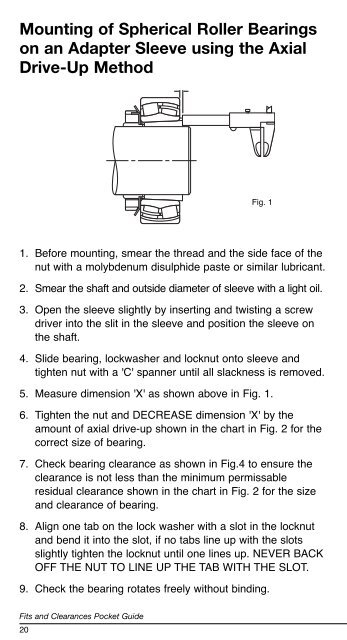
Mounting of Spherical Roller Bearings<br />
on an Adapter Sleeve using the Axial<br />
Drive-Up Method<br />
<strong>Fits</strong> <strong>and</strong> <strong>Clearances</strong> <strong>Pocket</strong> <strong>Guide</strong><br />
20<br />
Fig. 1<br />
1. Before mounting, smear the thread <strong>and</strong> the side face of the<br />
nut with a molybdenum disulphide paste or similar lubricant.<br />
2. Smear the shaft <strong>and</strong> outside diameter of sleeve with a light oil.<br />
3. Open the sleeve slightly by inserting <strong>and</strong> twisting a screw<br />
driver into the slit in the sleeve <strong>and</strong> position the sleeve on<br />
the shaft.<br />
4. Slide bearing, lockwasher <strong>and</strong> locknut onto sleeve <strong>and</strong><br />
tighten nut with a 'C' spanner until all slackness is removed.<br />
5. Measure dimension 'X' as shown above in Fig. 1.<br />
6. Tighten the nut <strong>and</strong> DECREASE dimension 'X' by the<br />
amount of axial drive-up shown in the chart in Fig. 2 for the<br />
correct size of bearing.<br />
7. Check bearing clearance as shown in Fig.4 to ensure the<br />
clearance is not less than the minimum permissable<br />
residual clearance shown in the chart in Fig. 2 for the size<br />
<strong>and</strong> clearance of bearing.<br />
8. Align one tab on the lock washer with a slot in the locknut<br />
<strong>and</strong> bend it into the slot, if no tabs line up with the slots<br />
slightly tighten the locknut until one lines up. NEVER BACK<br />
OFF THE NUT TO LINE UP THE TAB WITH THE SLOT.<br />
9. Check the bearing rotates freely without binding.<br />
Mounting of Spherical Roller Bearings with<br />
Adapter Sleeves<br />
Bearing Bore Reduction in Nominal Minimum Permissible<br />
Diameter mm Radial Clearance Axial Drive-Up tightening Residual Clearance<br />
angle<br />
1:12 taper<br />
over incl. min max min max nominal CN C3 C4<br />
30 40 0.025 0.030 0.40 0.45 100˚ 0.010 0.025 0.035<br />
40 50 0.030 0.035 0.45 0.55 120˚ 0.015 0.030 0.045<br />
50 65 0.030 0.035 0.45 0.55 90˚ 0.025 0.035 0.060<br />
65 80 0.040 0.045 0.60 0.70 120˚ 0.030 0.040 0.075<br />
80 100 0.045 0.055 0.70 0.85 140˚ 0.035 0.050 0.085<br />
100 120 0.050 0.060 0.75 0.90 0.045 0.065 0.110<br />
120 140 0.060 0.070 0.90 1.10 0.055 0.080 0.130<br />
140 160 0.065 0.080 1.00 1.30 0.060 0.100 0.150<br />
160 180 0.070 0.090 1.10 1.40 0.070 0.110 0.170<br />
180 200 0.080 0.100 1.30 1.60 0.070 0.110 0.190<br />
200 225 0.090 0.110 1.40 1.70 0.080 0.130 0.210<br />
225 250 0.100 0.120 1.60 1.90 0.090 0.140 0.230<br />
250 280 0.110 0.140 1.70 2.20 0.100 0.150 0.250<br />
280 315 0.120 0.150 1.90 2.40 0.110 0.160 0.280<br />
315 355 0.140 0.170 2.20 2.70 0.120 0.180 0.300<br />
355 400 0.150 0.190 2.40 3.00 0.130 0.200 0.330<br />
400 450 0.170 0.210 2.70 3.30 0.140 0.220 0.360<br />
450 500 0.190 0.240 3.00 3.70 0.160 0.240 0.390<br />
500 560 0.210 0.270 3.40 4.30 0.170 0.270 0.410<br />
560 630 0.230 0.300 3.70 4.80 0.200 0.310 0.460<br />
630 710 0.260 0.330 4.20 5.30 0.220 0.330 0.520<br />
710 800 0.280 0.370 4.50 5.90 0.240 0.390 0.590<br />
800 900 0.310 0.410 5.00 6.60 0.280 0.430 0.660<br />
900 1000 0.340 0.460 5.50 7.40 0.310 0.470 0.730<br />
1000 1120 0.370 0.500 5.90 8.00 0.360 0.530 0.800<br />
Fig. 2<br />
21