- Page 1 and 2: KX-TDA100 Model KX-TDA200 Thank you
- Page 3 and 4: System Components Table Other Cards
- Page 5 and 6: Important Safety Instructions SAFET
- Page 7 and 8: Precaution Keep the unit away from
- Page 9 and 10: The KX-TDA100E/KX-TDA200E, the KX-T
- Page 11 and 12: Precautions for Users in the United
- Page 13 and 14: Table of Contents 1 System Outline.
- Page 15 and 16: 3 Guide for the KX-TDA Maintenance
- Page 17 and 18: Section 1 System Outline This secti
- Page 19 and 20: Parallelled Telephone Features 1.1
- Page 21 and 22: 1.2.2 System Connection Diagram Tru
- Page 23 and 24: 1.2 Basic System Construction *1 Th
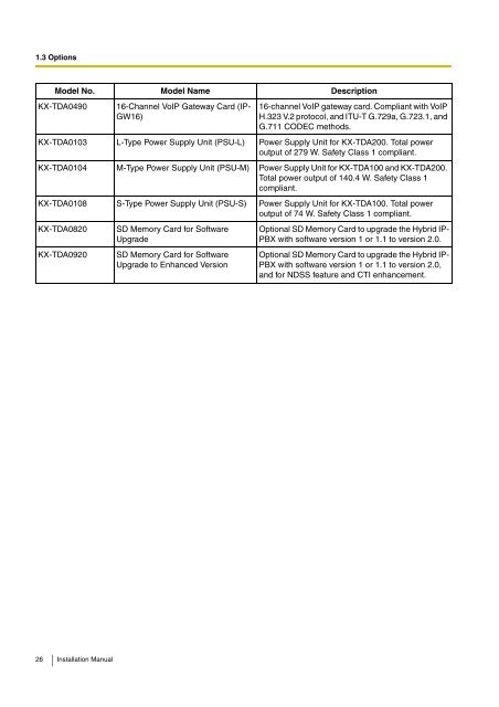
- Page 25: Model No. Model Name Description KX
- Page 29 and 30: 1.4.2 Characteristics Terminal Equi
- Page 31 and 32: 1.4 Specifications The following nu
- Page 33 and 34: Maximum Terminal Equipment 1.4 Spec
- Page 35 and 36: CS (1 unit) 4 PT-interface CS (1 un
- Page 37 and 38: Section 2 Installation This section
- Page 39 and 40: 2.1 Before Installation 3. Avoid us
- Page 41 and 42: 2.2.2 Names and Locations Inside Vi
- Page 43 and 44: Closing the Front Cover 2.2 Install
- Page 45 and 46: 2.2 Installation of the Hybrid IP-P
- Page 47 and 48: 2. Turn the 4 screws anticlockwise
- Page 49 and 50: 2.2.6 Backup Batteries Connection 2
- Page 51 and 52: 2.2 Installation of the Hybrid IP-P
- Page 53 and 54: Handling of the Cables 2.2 Installa
- Page 55 and 56: 2.2.8 Types of Connectors Connector
- Page 57 and 58: 2.2.9 Attaching a Ferrite Core A fe
- Page 59 and 60: 2.2.10 Fastening Amphenol Type Conn
- Page 61 and 62: 2.2.11 Wall Mounting (KX-TDA200) CA
- Page 63 and 64: 2.2.12 Wall Mounting (KX-TDA100) CA
- Page 65 and 66: 2.2.13 Floor Standing (KX-TDA200 On
- Page 67 and 68: Make sure that the surface behind t
- Page 69 and 70: Outside Installation Trunk 2.2 Inst
- Page 71 and 72: 2.3 Installation of the Main Proces
- Page 73 and 74: 2.3.2 MEC Card Function 2.3 Install
- Page 75 and 76: 2.4 Installation of the Trunk Cards
- Page 77 and 78:
2.4.2 DID8 Card Function 8-port DID
- Page 79 and 80:
2.4.3 CID/PAY8 Card Function 2.4 In
- Page 81 and 82:
2.4.5 E&M8 Card Function 8-port E &
- Page 83 and 84:
LED Indications Indication Colour D
- Page 85 and 86:
Pin Assignments RJ45 Connector for
- Page 87 and 88:
2.4.7 E1 Card Function 1-port E1 tr
- Page 89 and 90:
BNC (coaxial) Connector (RX) 1 2 LE
- Page 91 and 92:
Switch Settings Switch Type Usage a
- Page 93 and 94:
Maximum Cabling Distance of S0 Bus
- Page 95 and 96:
Switch Settings Switch Type Usage a
- Page 97 and 98:
Maximum Cabling Distance of Extensi
- Page 99 and 100:
Pin Assignments RJ45 Connector for
- Page 101 and 102:
2.4.11 IP-GW4 Card Function 2.4 Ins
- Page 103 and 104:
2.4.12 IP-GW4E Card Function 2.4 In
- Page 105 and 106:
2.4.13 IP-GW16 Card Function 2.4 In
- Page 107 and 108:
2.5 Installation of the Extension C
- Page 109 and 110:
2.5.2 DHLC8 Card Function 2.5 Insta
- Page 111 and 112:
LED Indications Indication Colour D
- Page 113 and 114:
Pin Assignments Amphenol Connector
- Page 115 and 116:
Pin Assignments Amphenol Connector
- Page 117 and 118:
Pin Assignments Amphenol Connector
- Page 119 and 120:
2.5.7 SLC16 and MSLC16 Cards Functi
- Page 121 and 122:
2.5.8 IP-EXT16 Card Function 2.5 In
- Page 123 and 124:
2.6 Installation of the Other Cards
- Page 125 and 126:
Pin Assignments 8-pin Terminal Bloc
- Page 127 and 128:
Pin Assignments 8-pin Terminal Bloc
- Page 129 and 130:
2.6.4 EIO4 Card Function 4-port ext
- Page 131 and 132:
Connection Diagram for External Sen
- Page 133 and 134:
2.6.6 MSG4 Card Function 4-channel
- Page 135 and 136:
LED Indications Indication Colour D
- Page 137 and 138:
2.7.2 Parallel Connection of the Ex
- Page 139 and 140:
2.7 Connection of Extensions 2.7.3
- Page 141 and 142:
With KX-T7600E Series DPT Using a M
- Page 143 and 144:
Connecting to a Master DPT To DLC8/
- Page 145 and 146:
2.8 Connection of DECT Portable Sta
- Page 147 and 148:
2.8.2 Procedure Overview 2.8 Connec
- Page 149 and 150:
2.8.3 Site Planning 2.8 Connection
- Page 151 and 152:
CS Coverage Area 2.8 Connection of
- Page 153 and 154:
2.8.4 Before Site Survey Use the KX
- Page 155 and 156:
1 2 3 4 Setting and Installing the
- Page 157 and 158:
2.8.5 Site Survey Using the KX-TCA2
- Page 159 and 160:
3. Repeat the steps 1 and 2 for oth
- Page 161 and 162:
2.8.6 After Site Survey 2.8 Connect
- Page 163 and 164:
Using a DHLC/DLC Card Refer to the
- Page 165 and 166:
2.8 Connection of DECT Portable Sta
- Page 167 and 168:
2.8 Connection of DECT Portable Sta
- Page 169 and 170:
PS Termination Confirm the followin
- Page 171 and 172:
2.8.8 Wall Mounting 2.8 Connection
- Page 173 and 174:
2.9 Connection of 2.4 GHz Portable
- Page 175 and 176:
2.9.2 Procedure Overview 2.9 Connec
- Page 177 and 178:
2.9.3 Site Planning 2.9 Connection
- Page 179 and 180:
CS Coverage Area 2.9 Connection of
- Page 181 and 182:
2.9.4 Before Site Survey Setting an
- Page 183 and 184:
2.9.5 Site Survey 2.9 Connection of
- Page 185 and 186:
2.9 Connection of 2.4 GHz Portable
- Page 187 and 188:
2.9.6 After Site Survey 2.9 Connect
- Page 189 and 190:
Using a DHLC/DLC Card Refer to the
- Page 191 and 192:
Registering the PS 2.9 Connection o
- Page 193 and 194:
Setting the System Lock 2.9 Connect
- Page 195 and 196:
PS Termination Confirm the followin
- Page 197 and 198:
Reference for Wall Mounting Please
- Page 199 and 200:
2.10 Connection of Doorphones, Door
- Page 201 and 202:
2.11 Connection of Peripherals 2.11
- Page 203 and 204:
For connecting a printer/PC with a
- Page 205 and 206:
2.12 Power Failure Connections 2.12
- Page 207 and 208:
Using BRI Card 2.12 Power Failure C
- Page 209 and 210:
2.13 Starting the Hybrid IP-PBX 2.1
- Page 211 and 212:
2.13 Starting the Hybrid IP-PBX To
- Page 213 and 214:
Section 3 Guide for the KX-TDA Main
- Page 215 and 216:
3.2 Connection 3.2.1 Connection Ser
- Page 217 and 218:
3.3 Installation of the KX-TDA Main
- Page 219 and 220:
3.3 Installation of the KX-TDA Main
- Page 221 and 222:
Section 4 Troubleshooting This sect
- Page 223 and 224:
PROBLEM PROBABLE CAUSE SOLUTION The
- Page 225 and 226:
(Continued from the previous page.)
- Page 227 and 228:
PROBLEM PROBABLE CAUSE SOLUTION PS
- Page 229 and 230:
4.1.5 Troubleshooting by Error Log
- Page 231 and 232:
List of Errors and Solutions 4.1 Tr
- Page 233 and 234:
Error Code Error Message PROBABLE C
- Page 235 and 236:
Error Code Error Message PROBABLE C
- Page 237 and 238:
Error Code Error Message PROBABLE C
- Page 239 and 240:
Error Code Error Message PROBABLE C
- Page 241 and 242:
Section 5 Appendix Installation Man
- Page 243 and 244:
5.1.2 Version 2.0 New Options Syste
- Page 245 and 246:
Index Installation Manual 245
- Page 247 and 248:
Installation of the Main Processing
- Page 249 and 250:
Index Installation Manual 249