

ericsson review - History of Ericsson - History of Ericsson
ericsson review - History of Ericsson - History of Ericsson
ericsson review - History of Ericsson - History of Ericsson

You also want an ePaper? Increase the reach of your titles
YUMPU automatically turns print PDFs into web optimized ePapers that Google loves.
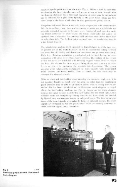
Fig. 3 X6558<br />
Interlocking machine with illuminated<br />
track diagram<br />
means <strong>of</strong> special point levers on the track, Fig. 2. When a track is made free<br />
for shunting the dwarf signals concerned are set at »out <strong>of</strong> use». In order that<br />
the shunting staff may know that local changing <strong>of</strong> points may be carried out,<br />
this is indicated by a pilot lamp lighting at the point lever. There are two<br />
other lamps at the lever which show in what position the points are set.<br />
The points and scotch blocks in the train roads are provided with electric motor<br />
drive in the ordinary way. Joint working points or points and scotch blocks are<br />
as a rule connected in pairs to the same lever. Points and track dogs for parking<br />
tracks connected to train tracks arc locked electrically but cannot be<br />
operated from a distance; the shunting staff therefore must throw these over<br />
to make them lock. The farthest point operated from the interlocking plant is<br />
-• km distant from it.<br />
The interlocking machine itself, supplied by Signalbolaget, is <strong>of</strong> the type now<br />
in general use on the State Railways. It has no mechanical locking between<br />
the levers but all locking and dependent movements are produced electrically-<br />
Each lever therefore constitutes a mechanical unit in itself having no other<br />
connection with other levers than electric circuits. The feature <strong>of</strong> the system<br />
is that the levers are furnished with blocking magnets which block or release<br />
the lever, the circuits for these magnets being drawn over contacts at other<br />
levers or relays for producing the requisite interdependence. The system<br />
provides great adaptability, particularly at large stations with complicated<br />
track systems and varied traffic. Thus, as stated, the train roads may be<br />
arranged for alternative roads.<br />
With an electrical interlocking plant covering an extensive track area it is<br />
not possible directly to watch over the area. In order that the interlocking<br />
plant attendant may be able at all times to follow what is taking place at the<br />
station this has been reproduced on an illuminated track diagram, arranged<br />
above the interlocking machine, see Fig. 3. Lamps on the track diagram<br />
indicate the signal pictures made by the main signals and the dwarf signals, also<br />
whether tracks are occupied by rolling stock or not. Free tracks are marked<br />
by lighted lamp and occupied tracks by unlighted lamps. The four signal pictures<br />
<strong>of</strong> the dwarf signals are marked by lamps <strong>of</strong> different colours. The main<br />
signals are indicated by red and green lamps which are directly connected in<br />
series with the signal lamps themselves.<br />
93


