Hydride Generation Atomic Absorption Spectroscopy Introduction
Hydride Generation Atomic Absorption Spectroscopy Introduction
Hydride Generation Atomic Absorption Spectroscopy Introduction

You also want an ePaper? Increase the reach of your titles
YUMPU automatically turns print PDFs into web optimized ePapers that Google loves.
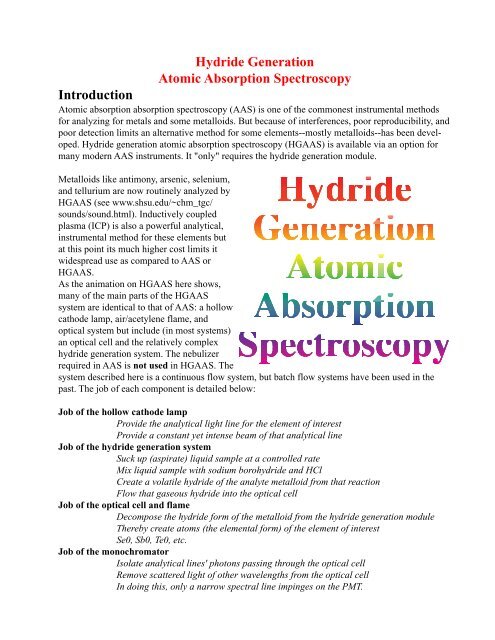
<strong>Hydride</strong> <strong>Generation</strong><br />
<strong>Atomic</strong> <strong>Absorption</strong> <strong>Spectroscopy</strong><br />
<strong>Introduction</strong><br />
<strong>Atomic</strong> absorption absorption spectroscopy (AAS) is one of the commonest instrumental methods<br />
for analyzing for metals and some metalloids. But because of interferences, poor reproducibility, and<br />
poor detection limits an alternative method for some elements--mostly metalloids--has been developed.<br />
<strong>Hydride</strong> generation atomic absorption spectroscopy (HGAAS) is available via an option for<br />
many modern AAS instruments. It "only" requires the hydride generation module.<br />
Metalloids like antimony, arsenic, selenium,<br />
and tellurium are now routinely analyzed by<br />
HGAAS (see www.shsu.edu/~chm_tgc/<br />
sounds/sound.html). Inductively coupled<br />
plasma (ICP) is also a powerful analytical,<br />
instrumental method for these elements but<br />
at this point its much higher cost limits it<br />
widespread use as compared to AAS or<br />
HGAAS.<br />
As the animation on HGAAS here shows,<br />
many of the main parts of the HGAAS<br />
system are identical to that of AAS: a hollow<br />
cathode lamp, air/acetylene flame, and<br />
optical system but include (in most systems)<br />
an optical cell and the relatively complex<br />
hydride generation system. The nebulizer<br />
required in AAS is not used in HGAAS. The<br />
system described here is a continuous flow system, but batch flow systems have been used in the<br />
past. The job of each component is detailed below:<br />
Job of the hollow cathode lamp<br />
Provide the analytical light line for the element of interest<br />
Provide a constant yet intense beam of that analytical line<br />
Job of the hydride generation system<br />
Suck up (aspirate) liquid sample at a controlled rate<br />
Mix liquid sample with sodium borohydride and HCl<br />
Create a volatile hydride of the analyte metalloid from that reaction<br />
Flow that gaseous hydride into the optical cell<br />
Job of the optical cell and flame<br />
Decompose the hydride form of the metalloid from the hydride generation module<br />
Thereby create atoms (the elemental form) of the element of interest<br />
Se0, Sb0, Te0, etc.<br />
Job of the monochromator<br />
Isolate analytical lines' photons passing through the optical cell<br />
Remove scattered light of other wavelengths from the optical cell<br />
In doing this, only a narrow spectral line impinges on the PMT.
Job of the photomultiplier tube (PMT)<br />
As the detector, the PMT determines the intensity of photons of the analytical line<br />
exiting the monochromator.<br />
The Hollow Cathode Lamp<br />
The hollow cathode lamp (HCL) uses a cathode made of the element of interest with a low internal<br />
pressure of an inert gas. A low electrical current (~ 10 mA) is imposed in such a way that the metal is<br />
excited and emits a few spectral lines characteristic of that element (for instance, Te 214.3 nm and a<br />
couple of other lines; Se 196 nm and other lines, etc.). The light is emitted directionally through the<br />
lamp's window, a window made of a glass transparent in the UV and visible wavelengths.<br />
<strong>Hydride</strong> <strong>Generation</strong> and Waste<br />
The reaction of many metalloid oxyanions with sodium borohydride and HCl produces a volatile<br />
hydride: H2Te, H2Se, H3As, H3Sb, etc. As with AAS, the oxidation state of the metalloid is crucial<br />
and care must be taken to produce the<br />
specific metalloid oxidation state before<br />
the sample is introduced into the hydride<br />
generation system.<br />
The time from reagent mixing and when<br />
the volatile hydride is separated from the<br />
liquid and sent to the optical cell is also<br />
important. The timing of that process is<br />
controlled by flowing reagents together<br />
using a peristaltic pump and tubing of<br />
specific lengths. After being mixed together<br />
the liquid mixture flows through a<br />
tube of a specific length (read this as a<br />
controlled reaction time) and is ultimately<br />
flowed into a gas/liquid separator where<br />
To optical cell<br />
heated in air/C2H4 flame<br />
0.35% 50%<br />
NaBH4 HCl<br />
<strong>Hydride</strong> generation reagents<br />
<strong>Hydride</strong> gas<br />
Peristaltic Pump<br />
Mixing/<br />
reaction<br />
coil<br />
<strong>Hydride</strong> Generator<br />
Gas/liquid<br />
separator<br />
the hydride and some gaseous hydrogen (produced by the NaBH4 + H2 reaction) bubble out and are<br />
purged (via a high purity inert gas) into the optical cell via a gas transfer line.<br />
Most of the reagents introduced into the system flow to a waste container, and since the acid content<br />
is very high, often approaching 50%, as with AAS, the waste container is glass and must be handled<br />
carefully and labeled well.<br />
The Optical Cell and Flame<br />
The optical cell is fused silica glass tube (transparent in the visible and UV wavelengths and thermally<br />
stable at high temperatures) through which the HCL's beam passes on the way to the monochromator<br />
and PMT. In some instruments it sits on top of the normal AAS air/acetylene flame. The<br />
gaseous, metalloidal hydride flows into the optical cell from the hydride generation module pushes<br />
by an inert purge gas. In the optical cell it decomposes into the elemental form which can absorb the<br />
HCL's beam.<br />
The Monochromator and PMT<br />
Tuned to a specific wavelength and with a specified slit width chosen, the monochromator isolates<br />
To<br />
waste
the hollow cathode lamp's analytical line. Since the basis for the HGAAS process, like AAS, is<br />
atomic ABSORPTION, the monochromator seeks to only allow the light not absorbed by the analyte<br />
atoms in the optical cell to reach the PMT. That is, before an analyte is aspirated, a measured signal<br />
is generated by the PMT as light<br />
from the HCL passes through the<br />
optical cell. When analyte atoms<br />
are present in the cell from<br />
hydride decomposition--while<br />
the sample is aspirated--some of<br />
that light is absorbed by those<br />
atoms (remember only volatile<br />
hydride gets to the optical cell<br />
and then only decomposed<br />
hydride produces the elemental<br />
form). This causes a decrease in<br />
PMT signal that is proportional<br />
to the amount of analyte. This<br />
last is true inside the linear range<br />
for that element using that slit<br />
Burner slot<br />
Top<br />
Air/C2H4<br />
flame<br />
Front<br />
Optical Cell<br />
Burner head<br />
<strong>Hydride</strong><br />
flows in<br />
here<br />
Optical Cell &<br />
Burner<br />
head<br />
Optical<br />
cell heated<br />
by<br />
air/C2H4<br />
flame<br />
Right side<br />
Flame<br />
and that analytical line. The signal is therefore a decrease in measure light: atomicabsorption spectroscopy.<br />
Acidic Content and Oxidation State of Samples and Standards<br />
The samples and standards are often prepared with duplicate acid concentrations to replicate the<br />
analyte's chemical matrix as closely as possible. In HGAAS, acid contents of samples and standards<br />
of 10% to 50% are common; this is much much higher than in normal AAS.<br />
The oxidation state of the analyte metalloid is important in HGAAS. For instance, HGAAS analysis<br />
of selenium requires the Se(IV) oxidation state (selenite). Se(VI), the more highly oxidized state of<br />
the element (selenate), responds erratically and non reproducibly in the system. Therefore, all selenium<br />
in Se calibration standards and Se containing samples must be in the Se(IV) form for analysis.<br />
This can be accomplished by oxidizing all Se in the sample to selenate using a strong oxidizer such<br />
as nitric acid or hydrogen peroxide (decomposing the excess oxidant) and then reducing the contained<br />
selenate to selenite with boiling HCl. After that reduction step, the final acid content is made<br />
up to the required content before the sample is introduced into the hydride generation module. The<br />
literature also suggests that the time from reduction to introduction into the hydride module is important:<br />
Shorter is best.<br />
Also important is the concentration of sodium borohydride and hydrochloric acid reagents feed into<br />
the hydride generation reaction vessel: optimization of this is important and may be different for<br />
different elements. Example concentrations are 0.35% NaBH4 and 50% HCl. Note that this acid<br />
content is not necessarily identical with the acid content of the samples and standards themselves.<br />
The reagent acid's content is aimed at producing a reproducible amount of hydride in the module.<br />
Double Beam Instruments<br />
The light from the HCL is split into two paths using a rotating mirror: one pathway passes through<br />
the optical cell and another around. Both beams are recombined in space so they both hit the PMT<br />
but separated in time. The beams alternate quickly back and forth along the two paths: one instant
the PMT beam is split by the rotating mirror and the sample beam passes through the cell and hits<br />
the PMT. The next instance, the HCL beam passes through a hole in the mirror and passes directly to<br />
the PMT without passing through the optical cell. The difference between these beams is the amount<br />
of light absorbed by atoms in the optical cell.<br />
The purpose of a double beam instrument is to help compensate for drift of the output of the hollow<br />
cathode lamp or PMT. If the HCL output drifts slowly the subtraction process described immediately<br />
above will correct for this because both beams will drift equally on the time scale of the analysis.<br />
Likewise if the PMT response changes the double beam arrangement take this into account.<br />
Ignition, Flame conditions, and Shut Down<br />
The process of lighting the AAS flame involves first putting the optical cell in place and connecting<br />
the hydride gas transfer line. Next the fuel and the oxidant are turned on and then the flame is lit<br />
with the instrument's auto ignition system (a small flame or red-hot glow plug). After only a few<br />
minutes the flame is stable. Deionized water or a dilute acid solution can be aspirated between<br />
samples (but experimentation is required to ascertain what produces the best reproducibility). An<br />
aqueous solution with<br />
Detector<br />
Monochromator<br />
0.35%<br />
NaBH4<br />
50%<br />
HCl<br />
Hollow cathode<br />
lamp (HCL)<br />
Volatile hydride<br />
Blank Std 1 Unk<br />
Std 2 Std 3<br />
the correct amount of<br />
acid and no analyte is<br />
often used as the blank.<br />
To stabilize the HGAAS<br />
system the acidic blank<br />
is often flowed through<br />
the sample inlet tube for<br />
5 or 10 minutes; although<br />
the longer this<br />
goes on, the more acidic<br />
waste is produced.<br />
Careful control of the<br />
fuel/air mixture is<br />
important because each<br />
element's response<br />
depends on successful<br />
decomposition of the volatile hydride in the heated optical cell. Remember that the flame's heat must<br />
break down the hydride and reproducibly create the elemental form of the analyte atom. Optimization<br />
is accomplished by aspirating a solution containing the element (with analyte content about that<br />
of the middle of the linear response range) and then adjusting the fuel/oxidant mix until the maximum<br />
light absorbance is achieved. Also the position of the burned head, optical cell, and sample<br />
uptake rate are similarly "tuned." Most computer controlled systems can save variable settings so<br />
that methods for different elements can be easily saved and reloaded.<br />
Shut down involves aspirating deionized water through all three inlet tubes (borohydride, acid, and<br />
sample inlets) for a short period and then closing the fuel off first. Most modern instruments control<br />
the ignition and shutdown procedures automatically. The plastic tubing that is stretched around the<br />
peristaltic pump head is loosened to length its lifetime. Finally the purge gas is turned off.<br />
These notes were written by Dr. Thomas G. Chasteen; Department of Chemistry, Sam Houston<br />
State University, Huntsville, Texas 77341. Copyright 2000.