cathodic protection monitoring via in-line inspection - PPSA, the ...
cathodic protection monitoring via in-line inspection - PPSA, the ...
cathodic protection monitoring via in-line inspection - PPSA, the ...

Create successful ePaper yourself
Turn your PDF publications into a flip-book with our unique Google optimized e-Paper software.
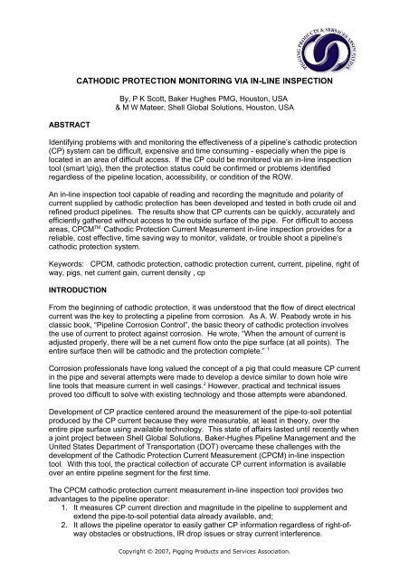
ABSTRACT<br />
CATHODIC PROTECTION MONITORING VIA IN-LINE INSPECTION<br />
By, P K Scott, Baker Hughes PMG, Houston, USA<br />
& M W Mateer, Shell Global Solutions, Houston, USA<br />
Identify<strong>in</strong>g problems with and <strong>monitor<strong>in</strong>g</strong> <strong>the</strong> effectiveness of a pipel<strong>in</strong>e’s <strong>cathodic</strong> <strong>protection</strong><br />
(CP) system can be difficult, expensive and time consum<strong>in</strong>g - especially when <strong>the</strong> pipe is<br />
located <strong>in</strong> an area of difficult access. If <strong>the</strong> CP could be monitored <strong>via</strong> an <strong>in</strong>-l<strong>in</strong>e <strong>in</strong>spection<br />
tool (smart \pig), <strong>the</strong>n <strong>the</strong> <strong>protection</strong> status could be confirmed or problems identified<br />
regardless of <strong>the</strong> pipel<strong>in</strong>e location, accessibility, or condition of <strong>the</strong> ROW.<br />
An <strong>in</strong>-l<strong>in</strong>e <strong>in</strong>spection tool capable of read<strong>in</strong>g and record<strong>in</strong>g <strong>the</strong> magnitude and polarity of<br />
current supplied by <strong>cathodic</strong> <strong>protection</strong> has been developed and tested <strong>in</strong> both crude oil and<br />
ref<strong>in</strong>ed product pipel<strong>in</strong>es. The results show that CP currents can be quickly, accurately and<br />
efficiently ga<strong>the</strong>red without access to <strong>the</strong> outside surface of <strong>the</strong> pipe. For difficult to access<br />
areas, CPCM TM Cathodic Protection Current Measurement <strong>in</strong>-l<strong>in</strong>e <strong>in</strong>spection provides for a<br />
reliable, cost effective, time sav<strong>in</strong>g way to monitor, validate, or trouble shoot a pipel<strong>in</strong>e’s<br />
<strong>cathodic</strong> <strong>protection</strong> system.<br />
Keywords: CPCM, <strong>cathodic</strong> <strong>protection</strong>, <strong>cathodic</strong> <strong>protection</strong> current, current, pipel<strong>in</strong>e, right of<br />
way, pigs, net current ga<strong>in</strong>, current density , cp<br />
INTRODUCTION<br />
From <strong>the</strong> beg<strong>in</strong>n<strong>in</strong>g of <strong>cathodic</strong> <strong>protection</strong>, it was understood that <strong>the</strong> flow of direct electrical<br />
current was <strong>the</strong> key to protect<strong>in</strong>g a pipel<strong>in</strong>e from corrosion. As A. W. Peabody wrote <strong>in</strong> his<br />
classic book, “Pipel<strong>in</strong>e Corrosion Control”, <strong>the</strong> basic <strong>the</strong>ory of <strong>cathodic</strong> <strong>protection</strong> <strong>in</strong>volves<br />
<strong>the</strong> use of current to protect aga<strong>in</strong>st corrosion. He wrote, “When <strong>the</strong> amount of current is<br />
adjusted properly, <strong>the</strong>re will be a net current flow onto <strong>the</strong> pipe surface (at all po<strong>in</strong>ts). The<br />
entire surface <strong>the</strong>n will be <strong>cathodic</strong> and <strong>the</strong> <strong>protection</strong> complete.” 1<br />
Corrosion professionals have long valued <strong>the</strong> concept of a pig that could measure CP current<br />
<strong>in</strong> <strong>the</strong> pipe and several attempts were made to develop a device similar to down hole wire<br />
l<strong>in</strong>e tools that measure current <strong>in</strong> well cas<strong>in</strong>gs. 2 However, practical and technical issues<br />
proved too difficult to solve with exist<strong>in</strong>g technology and those attempts were abandoned.<br />
Development of CP practice centered around <strong>the</strong> measurement of <strong>the</strong> pipe-to-soil potential<br />
produced by <strong>the</strong> CP current because <strong>the</strong>y were measurable, at least <strong>in</strong> <strong>the</strong>ory, over <strong>the</strong><br />
entire pipe surface us<strong>in</strong>g available technology. This state of affairs lasted until recently when<br />
a jo<strong>in</strong>t project between Shell Global Solutions, Baker-Hughes Pipel<strong>in</strong>e Management and <strong>the</strong><br />
United States Department of Transportation (DOT) overcame <strong>the</strong>se challenges with <strong>the</strong><br />
development of <strong>the</strong> Cathodic Protection Current Measurement (CPCM) <strong>in</strong>-l<strong>in</strong>e <strong>in</strong>spection<br />
tool. With this tool, <strong>the</strong> practical collection of accurate CP current <strong>in</strong>formation is available<br />
over an entire pipel<strong>in</strong>e segment for <strong>the</strong> first time.<br />
The CPCM <strong>cathodic</strong> <strong>protection</strong> current measurement <strong>in</strong>-l<strong>in</strong>e <strong>in</strong>spection tool provides two<br />
advantages to <strong>the</strong> pipel<strong>in</strong>e operator:<br />
1. It measures CP current direction and magnitude <strong>in</strong> <strong>the</strong> pipel<strong>in</strong>e to supplement and<br />
extend <strong>the</strong> pipe-to-soil potential data already available, and;<br />
2. It allows <strong>the</strong> pipel<strong>in</strong>e operator to easily ga<strong>the</strong>r CP <strong>in</strong>formation regardless of right-ofway<br />
obstacles or obstructions, IR drop issues or stray current <strong>in</strong>terference.<br />
Copyright © 2007, Pigg<strong>in</strong>g Products and Services Association.
While <strong>in</strong>terpretation of CPCM data cont<strong>in</strong>ues to be ref<strong>in</strong>ed, work to date has shown that <strong>the</strong><br />
tool generates much useful and accurate <strong>in</strong>formation – <strong>in</strong>formation that is unobta<strong>in</strong>able from<br />
a potential survey. The tools can quickly and accurately determ<strong>in</strong>e current density applied<br />
cont<strong>in</strong>uously along <strong>the</strong> pipel<strong>in</strong>e as well as <strong>the</strong> location and magnitude of current leav<strong>in</strong>g<br />
(rectifiers, bonds, anodes) or enter<strong>in</strong>g (bonds, shorts) by metallic connections.<br />
THE VALUE OF CURRENT MEASUREMENT<br />
Dur<strong>in</strong>g <strong>cathodic</strong> <strong>protection</strong>, steel is polarized by <strong>the</strong> effect of a flow of direct current, reduc<strong>in</strong>g<br />
<strong>the</strong> anodic area of <strong>the</strong> surface where corrosion occurs. If <strong>the</strong> current flow and polarization is<br />
great enough, <strong>the</strong> current will enter <strong>the</strong> steel at all po<strong>in</strong>ts, elim<strong>in</strong>at<strong>in</strong>g all local anodes and<br />
prevent<strong>in</strong>g corrosion. The relationship between current, potential and resistance is<br />
represented by <strong>the</strong> well-known equation E = IR. From this relationship, it is easy to illustrate<br />
that polarization and current density provide essentially equal <strong>in</strong>formation. Know<strong>in</strong>g <strong>the</strong><br />
value of one and <strong>the</strong> specific coat<strong>in</strong>g resistance at any po<strong>in</strong>t, it is possible to calculate <strong>the</strong><br />
o<strong>the</strong>r 3 .<br />
Based on this <strong>in</strong>formation, <strong>the</strong> current survey provided by <strong>the</strong> CPCM tool provides <strong>the</strong> same<br />
amount and type of <strong>in</strong>formation as a close <strong>in</strong>terval survey (CIS). The only advantage to <strong>the</strong><br />
potential survey is that well-established potential criteria are available to determ<strong>in</strong>e<br />
<strong>protection</strong>, while current density criteria are not.<br />
Development of suitable current density criteria to prove <strong>protection</strong> would certa<strong>in</strong>ly be<br />
beneficial and this project is currently planned. Used toge<strong>the</strong>r, current and potential<br />
measurements would allow for a complete characterization of <strong>the</strong> CP system and a complete<br />
understand<strong>in</strong>g of <strong>the</strong> performance of <strong>the</strong> coat<strong>in</strong>g system.<br />
BENEFITS TO CATHODIC PROTECTION CURRENT MONITORING<br />
While more work is needed to fully exploit all <strong>the</strong> capabilities of <strong>the</strong> <strong>in</strong>spection tool and <strong>the</strong><br />
result<strong>in</strong>g measurements, <strong>monitor<strong>in</strong>g</strong> CP current has a number of immediate practical<br />
advantages over external potential measurements:<br />
• Right-of-way access issues are elim<strong>in</strong>ated – Because <strong>the</strong> tool measures current<br />
from <strong>in</strong>side <strong>the</strong> pipe, access to <strong>the</strong> outside of <strong>the</strong> pipe is unnecessary. The pipel<strong>in</strong>e<br />
can be surveyed regardless of right-of-way condition or location. There is no need to<br />
deal with landowners, hire crews or boats, submit permits or even know <strong>the</strong> exact<br />
pipel<strong>in</strong>e location.<br />
• Stray current <strong>in</strong>terference is easily detected – Unlike potential data which requires<br />
<strong>in</strong>terpretation to f<strong>in</strong>d <strong>the</strong> presence of stray current <strong>in</strong>terference and can only guess at<br />
its magnitude or direction, current data clearly shows <strong>the</strong> exact location, magnitude<br />
and direction of unwanted current for external sources such as utilities, power l<strong>in</strong>es,<br />
DC rail or o<strong>the</strong>r CP systems.<br />
• IR drop is unimportant – IR voltage <strong>in</strong> <strong>the</strong> ground surround<strong>in</strong>g <strong>the</strong> pipe causes<br />
unwanted shifts <strong>in</strong> external potential measurements but has no impact on <strong>the</strong> current<br />
measurement. CPCM surveys do not require <strong>in</strong>terruption of CP systems. In fact,<br />
rectifiers should be <strong>in</strong> normal operational mode for best results.<br />
• Crowded right-of-ways are not problematic – The presence of o<strong>the</strong>r pipel<strong>in</strong>es <strong>in</strong><br />
close proximity <strong>in</strong> a s<strong>in</strong>gle right-of-way has no impact on current measurements.<br />
Only <strong>the</strong> current on <strong>the</strong> pipel<strong>in</strong>e be<strong>in</strong>g surveyed is measured, regardless of o<strong>the</strong>r<br />
pipel<strong>in</strong>es nearby.<br />
• Current data provides DCVG <strong>in</strong>formation <strong>in</strong> <strong>the</strong> same survey – Current density<br />
<strong>in</strong>formation duplicates <strong>the</strong> <strong>in</strong>formation produced by a DCVG survey, giv<strong>in</strong>g <strong>the</strong> effect<br />
of two surveys <strong>in</strong> a s<strong>in</strong>gle <strong>in</strong>spection. (CIS and DCVG)<br />
Page 2 of 7<br />
Copyright © 2007, Pigg<strong>in</strong>g Products and Services Association.
FIELD TRIALS<br />
Field Trial #1<br />
Field trials were performed <strong>in</strong> a 12.75” (324mm) 8 mile (12.9km) long ref<strong>in</strong>ed products<br />
pipel<strong>in</strong>e. This pipel<strong>in</strong>e was selected due to size, length, proximity to <strong>the</strong> <strong>in</strong>spection<br />
operations base and access to previous MFL (smart pig) data. (Fig. 1)<br />
A total of 5 Cathodic Protection Current Measurement test runs were performed on this<br />
pipel<strong>in</strong>e. The first three runs were used to ref<strong>in</strong>e <strong>the</strong> tool configuration and design, and <strong>the</strong><br />
last two runs tested <strong>the</strong> pipel<strong>in</strong>e’s <strong>cathodic</strong> <strong>protection</strong> system; first <strong>in</strong> a test mode, <strong>the</strong>n <strong>in</strong><br />
“normal” mode. Dur<strong>in</strong>g <strong>the</strong> test mode <strong>the</strong> <strong>cathodic</strong> <strong>protection</strong> rectifier and bonds were<br />
synchronously <strong>in</strong>terrupted and a sampl<strong>in</strong>g of <strong>the</strong> cas<strong>in</strong>gs and pipel<strong>in</strong>e cross<strong>in</strong>gs were bonded<br />
through an <strong>in</strong>terrupter us<strong>in</strong>g discern<strong>in</strong>g time schedules. An example of <strong>the</strong> data is shown <strong>in</strong><br />
Fig. 2.<br />
The pipel<strong>in</strong>e offered a challeng<strong>in</strong>g test due to <strong>the</strong> physical characteristics and features of <strong>the</strong><br />
pipel<strong>in</strong>e. Most of <strong>the</strong> features were due to <strong>the</strong> pipel<strong>in</strong>e age, service history and past repair<br />
methods. These features resulted <strong>in</strong> resistance changes to <strong>the</strong> pipe and consisted of<br />
numerous pipe changes and repair sleeves.<br />
All of <strong>the</strong>se features complicated <strong>the</strong> analysis but offered valuable <strong>in</strong>formation and<br />
experience <strong>in</strong> data <strong>in</strong>terpretation. Knowledge and experience were ga<strong>in</strong>ed with respect to<br />
<strong>the</strong> effect of <strong>the</strong> physical features <strong>in</strong>clud<strong>in</strong>g pipe types (i.e. seamless vs. bell & spigot) as well<br />
as wall thickness changes.<br />
One notable observation was that shock to <strong>the</strong> contact wheels provides a repeatable<br />
signature that can be filtered or used for alignment. The ILI MFL data proved to be vital <strong>in</strong><br />
this task and it became obvious that <strong>the</strong> <strong>in</strong>tegration of metal loss ILI and CP data adds<br />
<strong>in</strong>cremental value <strong>in</strong> tell<strong>in</strong>g <strong>the</strong> complete story of <strong>the</strong> status of a pipel<strong>in</strong>e (Fig. 3).<br />
The CPCM tool trial runs revealed that <strong>the</strong> pipel<strong>in</strong>e as orig<strong>in</strong>ally tested was <strong>in</strong> need of<br />
additional CP current. The test run allowed analysts to quantify <strong>the</strong> amount of current that<br />
was be<strong>in</strong>g received from <strong>the</strong> foreign rectifiers at ei<strong>the</strong>r end. The effects of add<strong>in</strong>g a rectifier,<br />
coat<strong>in</strong>g damage and areas of large current dra<strong>in</strong>s from shorts were also apparent.<br />
A rectifier and groundbed were <strong>in</strong>stalled prior to test runs #4 and #5. The additional current<br />
from <strong>the</strong> rectifier was captured dur<strong>in</strong>g <strong>the</strong> last two test runs and highlighted an area of bare<br />
pipe that was not visible before <strong>the</strong> additional current was applied. (Fig. 4)<br />
Field Trial #2<br />
A 12 <strong>in</strong>ch (324mm) crude oil pipel<strong>in</strong>e experienc<strong>in</strong>g sudden low potentials offered an<br />
opportunity for additional validation of <strong>the</strong> CPCM tool. The tool <strong>in</strong>formation ga<strong>in</strong>ed from this<br />
run identified <strong>the</strong> location of a shorted pipel<strong>in</strong>e caus<strong>in</strong>g low pipe-to-soil potentials. The short<br />
was subsequently removed and <strong>the</strong> pipe-to-soil potentials returned to <strong>the</strong>ir historical values<br />
(Fig 5).<br />
The data revealed <strong>the</strong> total current be<strong>in</strong>g applied to <strong>the</strong> pipel<strong>in</strong>e and <strong>the</strong> pattern of each<br />
current source. From this <strong>in</strong>formation one mislabeled rectifier negative was identified, an<br />
<strong>in</strong>sulator at an underwater tie-<strong>in</strong> was verified and <strong>the</strong> amount of current from <strong>the</strong> deliver<strong>in</strong>g<br />
and receiv<strong>in</strong>g stations was discerned.<br />
Page 3 of 7<br />
Copyright © 2007, Pigg<strong>in</strong>g Products and Services Association.
The tests conducted on this crude pipel<strong>in</strong>e revealed <strong>the</strong> importance of hav<strong>in</strong>g a “clean”<br />
pipel<strong>in</strong>e. There were areas of paraff<strong>in</strong> build-up that prevented <strong>the</strong> collection of usable data.<br />
The erratic voltage data collected <strong>in</strong> this area <strong>in</strong>dicated a lack of contact <strong>in</strong>tegrity. This poor<br />
contact was confirmed by <strong>the</strong> contact signal recorded dur<strong>in</strong>g <strong>the</strong> tool run. It was determ<strong>in</strong>ed<br />
that paraff<strong>in</strong> buildup on <strong>the</strong> pipe wall caused <strong>the</strong> contact wheels to experience lift off and<br />
large voltage sw<strong>in</strong>gs were recorded. It can be noted that even though some of <strong>the</strong> data was<br />
compromised due to <strong>in</strong>termittent contact loss <strong>the</strong> data was of value due to <strong>the</strong> cumulative<br />
nature of read<strong>in</strong>g current <strong>in</strong> <strong>the</strong> return path.<br />
CONCLUSIONS<br />
In conclusion, an <strong>in</strong>ternal <strong>in</strong>spection device that is able to read and record voltage drop<br />
caused by <strong>the</strong> flow of <strong>cathodic</strong> <strong>protection</strong> current has been developed and tested. In<br />
addition to current read<strong>in</strong>gs, <strong>the</strong> tool provides valuable <strong>in</strong>formation such as <strong>the</strong> location of<br />
bonds, shorts, rectifier current spread, and coat<strong>in</strong>g quality.<br />
The <strong>in</strong>spection technique is not affected by right-of-way conditions such as congestion,<br />
above-ground obstructions or <strong>the</strong> lack of test po<strong>in</strong>ts. The survey is equally effective whe<strong>the</strong>r<br />
<strong>the</strong> pipel<strong>in</strong>e traverses a body of water or under structures, or high traffic areas. The<br />
<strong>in</strong>spection is completed <strong>in</strong> a short time frame, reduc<strong>in</strong>g workload on personnel <strong>in</strong> comparison<br />
to o<strong>the</strong>r technologies while <strong>the</strong> CP systems are left <strong>in</strong> normal operat<strong>in</strong>g mode dur<strong>in</strong>g <strong>the</strong> test.<br />
Us<strong>in</strong>g a CPCM tool requires <strong>the</strong> ability of <strong>the</strong> pipel<strong>in</strong>e to accommodate an <strong>in</strong>-l<strong>in</strong>e <strong>in</strong>spection<br />
device (pig), sufficient cleanl<strong>in</strong>ess of <strong>the</strong> pipe wall, and a non-conductive medium such as<br />
br<strong>in</strong>e. Integration to ILI metal loss data provides maximum value. While acceptance of a<br />
current-ga<strong>in</strong> criteria is not currently listed <strong>in</strong> US DOT regulations or NACE RP-0169, both<br />
documents allow latitude for <strong>the</strong> operator <strong>in</strong> <strong>the</strong> use of any method as long as it provides at<br />
least <strong>the</strong> same level of assurance as those that are specifically listed 5 .<br />
REFERENCES<br />
1) Peabody, A.W., Control of Pipel<strong>in</strong>e Corrosion, p. 19, Houston: NACE, 1967<br />
2) Mark W. Mateer, Personal Communications<br />
3) nd<br />
Uhlig, Herbert H., Corrosion and Corrosion Control, 2 Edition, John Wiley & Sons,<br />
1971, page 219.<br />
4) Brasunas, Anton deS., Hamner, Norman E., NACE Basic Corrosion Course, p. 1-10<br />
NACE, 1970<br />
5) NACE International, RP0169-2002, Section 6, Houston: NACE, 2002.<br />
Page 4 of 7<br />
Copyright © 2007, Pigg<strong>in</strong>g Products and Services Association.
Figure 1 – CPCM Tool prior to test launch Figure 2 – Sample data from<br />
Test Run #4<br />
Figure 3 – Integration of MFL ILI and CPCM test data<br />
Page 5 of 7<br />
Copyright © 2007, Pigg<strong>in</strong>g Products and Services Association.
Figure 4 – Bare Pipe uncovered as a result of data<br />
Captured and analyzed dur<strong>in</strong>g <strong>the</strong> CPCM test run<br />
Page 6 of 7<br />
Copyright © 2007, Pigg<strong>in</strong>g Products and Services Association.
Figure 5- Pipe to soil potential before and after shorted pipe was removed<br />
Page 7 of 7<br />
Copyright © 2007, Pigg<strong>in</strong>g Products and Services Association.