

Spiral Retaining Rings & Wave Springs - Bearing Engineers, Inc.
Spiral Retaining Rings & Wave Springs - Bearing Engineers, Inc.
Spiral Retaining Rings & Wave Springs - Bearing Engineers, Inc.

You also want an ePaper? Increase the reach of your titles
YUMPU automatically turns print PDFs into web optimized ePapers that Google loves.
Engineering and Parts Catalog<br />
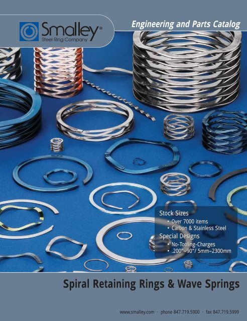
Stock Sizes<br />
• Over 7000 items<br />
• Carbon & Stainless Steel<br />
Special Designs<br />
• No-Tooling-Charges<br />
• .200"–90"/ 5mm–2300mm<br />
<strong>Spiral</strong> <strong>Retaining</strong> <strong>Rings</strong> & <strong>Wave</strong> <strong>Springs</strong><br />
www.smalley.com · phone 847.719.5900 · fax 847.719.5999
Copyright 2007 by<br />
Smalley Steel Ring Company<br />
Lake Zurich, IL 60047<br />
All rights reserved<br />
The following are trademarks of<br />
Smalley Steel Ring Company:<br />
Gap-Type, No-Tooling-Costs,<br />
No-Tooling-Charges, Overlap-Type.<br />
The following are registered<br />
trademarks of Smalley Steel Ring<br />
Company: All <strong>Springs</strong> Are Not<br />
Equal, Circular-Grain, Crest-to-<br />
Crest, Edgewound-Coiled, No Ears<br />
to Interfere, Quick Ship, Smalley,<br />
Spirawave, <strong>Wave</strong>Ring, Wavo.<br />
ABOUT SMALLEY<br />
ABOUT WAVE<br />
SPRINGS<br />
WAVE SPRINGS<br />
– FROM STOCK<br />
ABOUT RETAINING<br />
RINGS<br />
INTERNAL<br />
RETAINING RINGS<br />
– FROM STOCK<br />
EXTERNAL<br />
RETAINING RINGS<br />
– FROM STOCK<br />
ENGINEERING<br />
TABLE OF CONTENTS<br />
Smalley Steel Ring Company . . . . . . . . . . . . . . . . . . . . . . . . . . . 4-11<br />
General Spring Information / Comparitor . . . . . . . . . . . . . . . . 12-14<br />
Spring Applications . . . . . . . . . . . . . . . . . . . . . . . . . . . . . . . . . 15-17<br />
SERIES SPRING TYPE<br />
SSR Gap / Overlap Single Turn . . . . . . . . . . . . . . . . . 18-19<br />
SSR-N Narrow Single Turn . . . . . . . . . . . . . . . . . . . . . . . . . 20<br />
RW Wavo (Round Wire) Single Turn . . . . . . . . . . . . . . . 21<br />
SSB* <strong>Bearing</strong> Pre-Load Single Turn . . . . . . . . . . . . . . . 22-23<br />
<strong>Bearing</strong> Cross Reference Chart . . . . . . . . . . . . . . 24-25<br />
C / CS Crest-to-Crest / Shim Ends . . . . . . . . . . . . . . . . 26-31<br />
SSRS Shim . . . . . . . . . . . . . . . . . . . . . . . . . . . . . . . . . . . . 32<br />
Spring Tester / Fatigue Tester . . . . . . . . . . . . . . . . . . . . . . . . . . . . 33<br />
General Ring Information . . . . . . . . . . . . . . . . . . . . . . . . . . . . 34-35<br />
Ring Selection Guide / Ring Interchange Listing . . . . . . . . . . . 36-38<br />
Ring Applications . . . . . . . . . . . . . . . . . . . . . . . . . . . . . . . . . . 39-41<br />
Assembly / Removal Methods . . . . . . . . . . . . . . . . . . . . . . . . . 42-43<br />
SERIES RATING, RING TYPE<br />
VH Light Duty Single Turn, <strong>Spiral</strong> . . . . . . . . . . . . . . 44-45<br />
WH Medium Duty 2-Turn, <strong>Spiral</strong> . . . . . . . . . . . . . . . 46-48<br />
WHW <strong>Wave</strong>Ring, <strong>Spiral</strong> . . . . . . . . . . . . . . . . . . . . . . . . . . . 49<br />
WHT Medium Heavy Duty 2-Turn, <strong>Spiral</strong> . . . . . . . . . 50-51<br />
WHM Heavy Duty 2-Turn, <strong>Spiral</strong> . . . . . . . . . . . . . . . . . 52-53<br />
FHE Heavy Duty Single Turn, Snap . . . . . . . . . . . . . . 54-55<br />
VHM* Light Duty Single Turn, <strong>Spiral</strong> . . . . . . . . . . . . . . 56-57<br />
EH* Aerospace, <strong>Spiral</strong> . . . . . . . . . . . . . . . . . . . . . . . . 58-59<br />
DNH* DIN, <strong>Spiral</strong> . . . . . . . . . . . . . . . . . . . . . . . . . . . . 60-61<br />
FH* DIN, Snap . . . . . . . . . . . . . . . . . . . . . . . . . . . . . 62-63<br />
SERIES RATING, RING TYPE<br />
VS Light Duty Single Turn, <strong>Spiral</strong> . . . . . . . . . . . . . . 64-65<br />
WS Medium Duty 2-Turn, <strong>Spiral</strong> . . . . . . . . . . . . . . . 66-68<br />
WSW <strong>Wave</strong>Ring, <strong>Spiral</strong> . . . . . . . . . . . . . . . . . . . . . . . . . . . 69<br />
WST Medium Heavy Duty 2-Turn, <strong>Spiral</strong> . . . . . . . . . 70-71<br />
WSM Heavy Duty 2-Turn, <strong>Spiral</strong> . . . . . . . . . . . . . . . . . 72-73<br />
FSE Heavy Duty Single Turn, Snap . . . . . . . . . . . . . . 74-75<br />
VSM* Light Duty Single Turn, <strong>Spiral</strong> . . . . . . . . . . . . . . 76-77<br />
ES* Aerospace, <strong>Spiral</strong> . . . . . . . . . . . . . . . . . . . . . . . . 78-79<br />
DNS* DIN, <strong>Spiral</strong> . . . . . . . . . . . . . . . . . . . . . . . . . . . . 80-81<br />
FS* DIN, Snap . . . . . . . . . . . . . . . . . . . . . . . . . . . . . 82-83<br />
*Metric Series<br />
Special Designs . . . . . . . . . . . . . . . . . . . . . . . . . . . . . . . . . . . . . . . 84<br />
Introduction to Smalley Engineering . . . . . . . . . . . . . . . . . . . . . . 85<br />
Materials / Finishes . . . . . . . . . . . . . . . . . . . . . . . . . . . . . . . . . 86-90<br />
Spring Design . . . . . . . . . . . . . . . . . . . . . . . . . . . . . . . . . . . . . 91-95<br />
Ring Design . . . . . . . . . . . . . . . . . . . . . . . . . . . . . . . . . . . . . . 96-101<br />
Smalley Website . . . . . . . . . . . . . . . . . . . . . . . . . . . . . . . . . . 102-103<br />
Spring Checklist . . . . . . . . . . . . . . . . . . . . . . . . . . . . . . . . . . . . . 104<br />
Ring Checklist . . . . . . . . . . . . . . . . . . . . . . . . . . . . . . . . . . . . . . 105<br />
How to Order . . . . . . . . . . . . . . . . . . . . . . . . . . . . . . . . . . . 106-107<br />
Glossary . . . . . . . . . . . . . . . . . . . . . . . . . . . . . . . . . . . . . . . . 108-109
COMPANY PROFILE<br />
Founded in 1918 as a supplier of precision automotive piston<br />
rings, Smalley Steel Ring Company had many years of successful<br />
growth in an expanding marketplace. Having had a variety of<br />
products through out the years, it wasn’t until 1963, when present<br />
ownership began the development of products in the wire forming<br />
industry. <strong>Spiral</strong> <strong>Retaining</strong> <strong>Rings</strong> and <strong>Wave</strong> <strong>Springs</strong> emerged and<br />
Smalley developed into a reputable manufacturer of precision<br />
rings, springs & wire forms. But one thing never changed from<br />
years back, and that is our commitment to providing ever-higher<br />
levels of quality, performance, deliverability, and value to our<br />
customers. Today, Smalley<br />
“ One thing has never changed... and that is our commitment<br />
to providing ever-higher levels of quality, performance,<br />
deliverability, and value to our customers.”<br />
Steel Ring Company is a<br />
market leader in the<br />
industrial retaining ring and<br />
wave/compression spring<br />
business; a position we work<br />
hard to maintain and build<br />
upon.<br />
Every Smalley ring and<br />
spring is engineered and manufactured to the highest quality<br />
standards using skills and processes we have honed over three<br />
quarters of a century. Our obsession with quality, combined with<br />
our near-perfect record of on-time delivery, has earned us an<br />
approved supplier status with leading OEM manufacturers around<br />
the world. Due to the ceaseless demands we place upon ourselves,<br />
Smalley has won the coveted title of Preferred Source in the most<br />
demanding applications: automotive, agriculture, aerospace,<br />
electronics, appliance, and industrial.<br />
While we are understandably proud of the recognition we have<br />
received, ultimately, it is our products that set us apart. Unlike<br />
stamped rings and springs, which are die-stamped through the<br />
metal grain, our edgewound rings and springs have a<br />
circumferential metal grain structure that gives them<br />
exceptional strength, dimensional stability, and<br />
predictable performance characteristics.<br />
Finally, every Smalley ring and spring is backed by<br />
our continued support. We are constantly<br />
searching ways to expand and improve our<br />
Customer Service and Engineering/Technical<br />
Assistance. We welcome your comments and<br />
your design challenges. <strong>Engineers</strong> are available<br />
to help assist with any design questions.<br />
With regional offices in Europe, we are<br />
prepared to service our European customers.<br />
Smalley provides customized global supply<br />
chain solutions, to meet your<br />
WORLDWIDE manufacturing<br />
requirements, in Europe, Asia Pacific and<br />
the America's.<br />
Please call us at +1 847.719.5900 or visit<br />
our website today!<br />
4 WWW.SMALLEY.COM
PRODUCTS<br />
All of Smalley’s wave springs and retaining rings are manufactured with our unique<br />
edgewinding manufacturing process. This eliminates any tooling charges, greatly<br />
increases design flexibility and reduces leadtimes as dies do not have to be produced.<br />
WAVE SPRINGS<br />
<strong>Wave</strong> springs are precise flat wire compression<br />
springs that fit into assemblies that other springs<br />
cannot. Since the overall lengths and operating<br />
heights of wave springs are lower than those of<br />
conventional round wire springs, they will often<br />
reduce the size of an assembly by as much as 50%.<br />
Of course, this will also reduce the part weight<br />
and raw material cost of every spring produced.<br />
RETAINING RINGS<br />
GENERAL INFO<br />
Unlike die-stamped circlips / retaining rings, Smalley<br />
<strong>Spiral</strong> <strong>Retaining</strong> <strong>Rings</strong> and Snap <strong>Rings</strong> are coiled on edge<br />
to the exact diameter required. They have a uniform<br />
cross-section (or to use our terminology, No Ears To<br />
Interfere TM within an assembly) and are free of burrs.<br />
Smalley spiral retaining rings meet military and aerospace<br />
specifications and are found in thousands of mechanical<br />
products around the world.<br />
CALL SMALLEY AT 847.719.5900 5<br />
SMALLEY
RAW MATERIAL<br />
As we meet the increasing demand for more raw<br />
material sizes, the flat wire rolling mill operation in<br />
our plant continues to grow. Years ago, Smalley began<br />
a vertical integration that has evolved into the<br />
production of hundreds of material cross-sections in a<br />
wide variety of alloys.<br />
6 WWW.SMALLEY.COM
MANUFACTURING<br />
Edgewinding, also known as “The No-Tooling-Cost<br />
Process”, is our precision forming operation that coils<br />
pre-tempered flat wire on edge to create a near-perfect<br />
circle. (Visualize a Slinky ® , the coiled metal toy which<br />
has delighted generations of children.) Circular-Grain ®<br />
metallurgy gives our products strength and stability far<br />
superior to that of conventional retaining rings and<br />
wave washers which are simply stamped through the<br />
metal grain. Smalley edgewound products can be coiled<br />
to your exact specification in any diameter and with any<br />
number of turns (layers or coils), effectively eliminating<br />
material waste.<br />
PROTOTYPES<br />
Wire Flattening<br />
About the easiest way to test a theoretical design is to<br />
produce a working prototype – a task at which Smalley<br />
excels. A prime example is the development of a custom<br />
wave spring. We can adjust dimensions, by changing the<br />
number of waves and the number of turns, and trying<br />
different combinations of spring variables. Finally, we<br />
test for function, before production, so we know we<br />
have it right.<br />
Smalley-produced prototypes are also the most<br />
economical way to provide results on a trial-and-error<br />
basis. From one to a thousand pieces, we can produce,<br />
try, modify, and reproduce your design as often as<br />
necessary – all without special tooling costs.<br />
GENERAL INFO<br />
As flexible as it is precise, our edgewinding process<br />
accommodates your design changes without the need for<br />
additional tooling and die modifications. This facilitates your<br />
developmental work, allowing us to produce your lowquantity<br />
custom orders and your working prototypes quickly<br />
and economically. Even after your initial prototype is<br />
produced, or in mid-stream production, our edgewinding<br />
process allows us to alter your design or dimensions with<br />
simple machine adjustments or a change in raw material size.<br />
After the revised specifications are approved, we complete<br />
and document the final setup. Then, we quickly resume<br />
production of your order, whether it consists of one part or<br />
one million.<br />
Wire Mill<br />
Conventional Stamping Process<br />
Edgewinding Process<br />
CALL SMALLEY AT 847.719.5900 7<br />
SMALLEY
FINISHED PARTS<br />
WAREHOUSE<br />
Smalley maintains a substantial parts inventory of every cataloged/standard retaining<br />
ring and wave spring – in both carbon and stainless steel. We do this to meet our JIT<br />
deliveries as well as any immediate requirement that you may have. In the rare<br />
circumstance that our inventory runs low, we can quickly replenish any item overnight.<br />
In addition to our finished parts, we house a vast inventory of raw material sizes,<br />
stocked in thousands of pounds of flat wire. We are always ready to meet your needs<br />
for a quick turnaround in low to high quantities of existing or new designs.<br />
8 WWW.SMALLEY.COM
CUSTOMER SERVICE<br />
Smalley is dedicated to giving you the most positive, efficient, and economical service possible—<br />
each and every day. We continually train our staff on every important aspect of our business. We<br />
can split shipments to suit your “just-in-time” delivery requirements. We offer you lower prices<br />
for your annual higher-usage orders. Please contact us directly for complete details and ideas on<br />
how you can purchase economically.<br />
GENERAL SALES INFORMATION<br />
DESCRIPTION: The product descriptions in this catalog are intended to provide the user with<br />
practical information for application selection. Since it is not possible to include<br />
complete detail on all parts, please contact Smalley for any information not<br />
included in the description which may be critical for a specific application.<br />
QUOTATIONS: We will provide written or verbal quotations as requested.<br />
CALL SMALLEY AT 847.719.5900<br />
RETURNS: Parts not stocked which must be specially manufactured are not returnable<br />
except by special arrangement and will be subject to cancellation charges.<br />
Stocked parts may be returned for credit at a standard restocking charge<br />
(subject to condition). All returns of stocked parts must be made within 30<br />
days from date of receipt of material.<br />
DELIVERY: Parts carried in stock normally will be shipped within 48 hours after<br />
receipt of an order. Special parts are normally delivered in 3 weeks (if<br />
no special processes are required) or as previously arranged.<br />
CERTIFICATIONS: Standard Certificate of Conformance will be supplied at no charge.<br />
Material and other Certifications for plating, load, etc. will be furnished<br />
as quoted.<br />
TRANSPORTATION: As specified by the customer. In the absence of instructions, the shipping<br />
method will be selected by us. Insurance will be provided only at the customer’s<br />
request.<br />
TERMS: 1/10/NET 30 on open accounts. For consideration of an open account,<br />
customers are requested to supply banking information and at least 3<br />
commercial credit references.<br />
Go to www.smalley.com for Terms and Conditions, which apply.<br />
F.O.B.: Factory, Lake Zurich, Illinois, USA<br />
PACKAGING: <strong>Rings</strong> and springs 1 5 ⁄16" in diameter and under are bulk packaged. <strong>Rings</strong> and<br />
springs 1 3 ⁄8" and over in diameter are generally tube (coin) packaged in lengths<br />
10 to 18 inches.<br />
Smalley is the proud recipient of the<br />
GM Supplier of the Year Award.<br />
GENERAL INFO<br />
SMALLEY<br />
9
GENERAL INFO<br />
SMALLEY<br />
ENGINEERING & DESIGN ASSISTANCE<br />
Smalley’s engineering staff is always ready to address your<br />
application requirements. Usually, the sooner we are able to<br />
review what you need, the easier the solution will be. Please<br />
call us today.<br />
We invite you to draw upon our resources. Over the years,<br />
Smalley engineers have built an extensive library of over 5000<br />
applications while designing rings and springs in mechanical<br />
components and assemblies. In addition, we offer computeraided<br />
spring-design alternatives to meet your specifications.<br />
There are many more options that we would be pleased to<br />
review with you once your design criteria are established. We<br />
are ready to help you with the selection of a standard part<br />
from our vast inventory, or to modify a standard part to meet<br />
your exact needs.<br />
We are pleased to offer you additional step-by-step resources.<br />
The “Designing Specials” section of this catalog will help you<br />
determine basic retaining ring and wave spring specifications.<br />
We also invite you to try the design section on our website for<br />
step-by-step interactive design guidelines and options. As you<br />
can see, we are well-equipped to help you develop the best<br />
design solution possible, just as we have for thousands of other<br />
companies in diverse industries.<br />
NEED A SAMPLE?<br />
We offer free samples of any ring<br />
or spring found in our catalog.<br />
Inspection<br />
Department<br />
SPECIALS<br />
At Smalley, specials are standard. It’s easy to get a custom part<br />
from Smalley. With No-Tooling-Charges, die costs, or<br />
other fixture charges, we can manufacture a new ring or spring<br />
design in just two weeks or to meet your delivery schedules.<br />
Fast, precise, and economical — that’s how Smalley produces<br />
rings and springs, in short runs or high volumes. If you can’t<br />
find a standard part to meet your needs from the wide<br />
selection in our catalog, please contact our engineering<br />
department for immediate assistance with your special design<br />
requirements. And please note: Smalley <strong>Rings</strong> and <strong>Springs</strong> are<br />
available from .200" to 90" in diameter.<br />
CAD DOWNLOADS<br />
Visit our website for CAD downloads in 91 different formats.<br />
It’s easy to search and select a standard part for a quick upload<br />
to your computer.<br />
10 WWW.SMALLEY.COM
QUALITY ASSURANCE<br />
Smalley’s Total Quality Management philosophy dictates our<br />
commitment to quality and customer satisfaction. While this<br />
commitment has earned us official certification (ISO 9001,<br />
ISO/TS 16949 and AS 9100), quality assurance and customer<br />
satisfaction mean much more at Smalley. They are tradition,<br />
the very foundation upon which we have built our company.<br />
From the beginning, we have never lost sight of our goal: “to<br />
supply Smalley customers with uncompromising quality and<br />
service.”<br />
Smalley is committed to a quality policy that requires<br />
conformance to specification with controlled lot variation<br />
about the target, statistical quality control, defect prevention,<br />
and annual improvement in process and product. This is a<br />
company-wide commitment involving every Smalley<br />
employee. Each person works towards excellence, individually<br />
and cooperatively, to provide superior products and services.<br />
Our goal... to supply Smalley customers with<br />
uncompromising quality and service.<br />
“<br />
”<br />
A history of quality and strict compliance with military and<br />
aerospace standards has earned Smalley an approved supplier<br />
status with many leading original equipment manufacturers<br />
worldwide. Smalley has worked diligently to become their<br />
Preferred Source for spiral retaining rings and wave springs.<br />
In accordance with the requirements of ISO 9001,<br />
ISO/TS 16949 and AS 9100, we have established and are<br />
continuously improving our quality systems. Use of the<br />
latest technology, including statistical tools, has helped us<br />
achieve and maintain the world-class quality associated<br />
with the Smalley name for more than 40 years.<br />
Smalley uses statistical quality control tools to assure the<br />
capability and stability of our coiling process. To begin with,<br />
we identify common dimensions to monitor and special<br />
causes of variation in the product. Then, we collect and<br />
analyze data on these critical dimensions. We perform<br />
disciplined sampling and take measurements during in-line<br />
and final inspection, and yet again, during pre-shipping<br />
inspection.<br />
We make formal SQC in-house training programs mandatory<br />
for many Smalley employees involved with manufacturing.<br />
This training has noticeably developed quality awareness and<br />
responsibility at all levels. Our employees have a clear<br />
understanding of what is expected, a means of regulating their<br />
processes and checking their output, and statistical tools to<br />
determine when machine adjustments are required.<br />
Smalley’s machine capability studies help us identify sources of<br />
variation before they become a problem. We analyze the<br />
capabilities of all production machinery in primary and<br />
secondary operations, heat treating, and finishing. In addition,<br />
we follow our own meticulous procedures to determine the<br />
reproducibility and repeatability of our gauging systems.<br />
Due to the careful documentation of our quality, many<br />
Smalley customers have found that they can reduce or even<br />
eliminate their incoming inspections of our product. Many of<br />
our accounts have also revised their policy of dual sourcing<br />
and confidently rely on Smalley as their single source of<br />
retaining rings, wave springs, snap rings,<br />
expanders, and other wire forms.<br />
Defect prevention, or near-zero defects, is<br />
a key goal at Smalley. We use the latest<br />
automated inspection techniques to<br />
monitor production. As a result, we are<br />
constantly studying the causes of variation,<br />
improving upon and developing processes with capability<br />
indexes (Cpk) exceeding 1.33.<br />
Continuous improvement is an integral part of Smalley’s<br />
quality plan. We require each of our departments to design<br />
and implement projects to improve their respective systems.<br />
QUALITY POLICY<br />
Smalley has established and is continuously improving upon a<br />
program that is designed to meet the following objectives:<br />
• Total product conformance in terms of drawings,<br />
specifications and contractual requirements.<br />
• 100% on-time delivery performance.<br />
• Superior products with exceptional value.<br />
GENERAL INFO<br />
• Prompt, professional and courteous response in every facet<br />
of design, manufacturing, sales, and customer service.<br />
• Continued development and use of the latest technology.<br />
CALL SMALLEY AT 847.719.5900 11<br />
SMALLEY
WAVE SPRING INTRODUCTION<br />
SPRINGS<br />
ALL SPRINGS ARE NOT EQUAL ®<br />
Smalley <strong>Wave</strong> <strong>Springs</strong> offer the unique advantage of space savings when used to replace coil springs. By reducing spring<br />
operating height, wave springs also produce a decrease in the spring cavity. With a smaller assembly size and less<br />
material used in the manufacturing process, a cost savings is realized.<br />
<strong>Wave</strong> springs operate as load bearing devices. They take up play and compensate for dimensional variations within<br />
assemblies. A virtually unlimited range of forces can be produced whereby loads build either gradually or abruptly to<br />
reach a predetermined working height. This establishes a precise spring rate in which load is proportional to deflection.<br />
Functional requirements are necessary for both dynamic and static spring applications. Special performance<br />
characteristics are individually built into each spring to satisfy a variety of precise operating conditions. Typically, a wave<br />
spring will occupy an extremely small area for the amount of work it performs. The use of this product is demanded,<br />
but not limited to tight axial and radial space constraints.<br />
SMALLEY SPRING<br />
PRODUCT PERFORMANCE<br />
COIL SPRING<br />
With their smooth, circular coiled sinusoidal wave form, and rolled round edges of pre-tempered raw material,<br />
Smalley’s edgewound <strong>Wave</strong> <strong>Springs</strong> offer many advantages over die stamped products.<br />
Loads and spring rates are more accurate, more predictable, and may be toleranced better than 50 percent tighter<br />
than stampings. The force of a Smalley <strong>Wave</strong> Spring will increase at a uniform rate throughout most of its<br />
available deflection.<br />
By any criteria, Smalley <strong>Wave</strong> <strong>Springs</strong> offer their users higher dependability and better performance. Since they<br />
are produced from full hard, pre-tempered raw material, there is no risk of distorting the spring during a<br />
hardening heat treatment. By contrast, subsequent manufacturing procedures for stamped wavy washers can lead<br />
to problems such as fatigue cracking and inaccurate or inconsistent loading between springs. All told, the<br />
metallurgy, the mechanical properties and the uniform dimensional stability of the Smalley edgewound <strong>Wave</strong><br />
Spring provide a component for precision quality applications.<br />
12 WWW.SMALLEY.COM
WAVE SPRING TYPES<br />
GAP & OVERLAP TYPE<br />
Conventional Gap and Overlap Type <strong>Wave</strong> <strong>Springs</strong> are used in a wide<br />
variety of applications. For short deflections and low-medium forces,<br />
they function with precision and dependability.<br />
These two types of Smalley <strong>Wave</strong> <strong>Springs</strong> permit radial expansion or<br />
growth in diameter within a cavity, without the binding or hang-up<br />
normally associated with die stamped wave washers. Just as their terms<br />
imply, the gap type is split to retain a gap between the ends; while the<br />
overlap type has overlapping ends. Thus, the ends are free to move<br />
circumferentially as the spring outside diameter grows during<br />
compression.<br />
For example, the O.D. of a Gap Type <strong>Wave</strong> Spring would fit .020 loose<br />
per side in a bore. Its I.D. clears a shaft by .010 per side. As the spring<br />
is deflected, the O.D. and I.D. grow larger until the O.D. contacts the<br />
bore. Continued deflection causes the gap ends to move closer together<br />
while the O.D. presses against the bore. An Overlap Type <strong>Wave</strong> Spring<br />
permits this type of cycling action in a similar manner.<br />
WAVE SPRING INTRODUCTION<br />
CREST-TO-CREST ®<br />
Gap Type <strong>Wave</strong> <strong>Springs</strong><br />
Overlap Type <strong>Wave</strong> <strong>Springs</strong><br />
Crest-to-Crest <strong>Wave</strong> <strong>Springs</strong> are prestacked in series, decreasing the<br />
spring rate proportionally to the number of turns. Uses are typically<br />
applications requiring low-medium spring rates and large deflections<br />
with low-medium forces. Among major advantages, this design<br />
eliminates the need to keep the wave crests aligned. The need to use<br />
a key locating device, or to insert a shim between individual springs<br />
is not necessary. Because the spring is integrally formed, the wave<br />
peaks hold their configuration.<br />
As a replacement for helical compression springs, Crest-to-Crest<br />
springs can develop similar forces, yet occupy one-half ( 1 ⁄2) or less the<br />
axial space. This allows for strict space constraints. Crest-to-Crest<br />
<strong>Wave</strong> <strong>Springs</strong> will maintain the same force and load specifications of<br />
a conventional round wire spring, but with the advantages of<br />
resultant lowered and compacted operating heights, free heights, and<br />
solid heights.<br />
CALL SMALLEY AT 847.719.5900 13<br />
SPRINGS
WAVE SPRING INTRODUCTION<br />
SPRINGS<br />
WAVE SPRING TYPES (cont’d)<br />
CREST-TO-CREST ® WITH OPTIONAL SHIM ENDS<br />
Crest-to-Crest <strong>Wave</strong> <strong>Springs</strong> are also available with squared-shim ends. Shim ends<br />
provide a 360˚ contact surface when compared to the wave point contact of plain<br />
ends. The shim-ends under load, more evenly distribute the springs force upon<br />
adjacent components. This feature is similar to the concept of double-disc grinding<br />
springs for a flat surface. Shim ends have also been used to affix springs to mating<br />
components, as a flat locating surface that may be attached by various methods in<br />
the assembly.<br />
WAVO ®<br />
NESTED<br />
Wavo <strong>Springs</strong> are produced from round-section wire to provide<br />
higher loads while maintaining the accurate loading found in wave<br />
springs. As an alternative to Belleville <strong>Springs</strong>, the Wavo provides<br />
similar loads but with an accurate, predictable spring rate.<br />
Nested <strong>Wave</strong> <strong>Springs</strong> are pre-stacked in parallel from one<br />
continuous filament of flat wire. The need to stack individual<br />
springs for higher loads is no longer necessary. Nested springs<br />
result in a spring rate that increases proportionately to the<br />
number of turns. They can exert tremendous forces, yet maintain<br />
the precision of a circular-grain wave spring. In many<br />
applications, Nested <strong>Wave</strong> <strong>Springs</strong> replace Belleville <strong>Springs</strong>,<br />
particularly in cases where a high but accurate force is needed.<br />
LINEAR EXPANDERS<br />
Linear expanders are a continuous wave formed (marcelled)<br />
wire length produce from spring tempered materials. They<br />
act as a load bearing device having approximately the same<br />
load/deflection characteristics as a wave spring.<br />
Forces act axially or radially depending on the installed<br />
position. Axial pressure is obtained by lying the expander flat<br />
in a straight line. Circular wrapping the expander produces a<br />
radial force or outward pressure. Linear expanders are<br />
available cut to length or as a continuous coil, for the user to<br />
cut as needed.<br />
14 WWW.SMALLEY.COM
PRESSURE RELIEF VALVE<br />
An exact load applied to the top sealing plate was<br />
accomplished using a flat wire wave spring. Air pressure<br />
entering the top slots forces the plate away from the sealing<br />
surface providing the pressure relief mechanism.<br />
CLUTCH DRIVE<br />
Pressure on the round belt is produced by compressing<br />
the Wavo ® Spring thru the sheave halves. The top<br />
threaded cap rotates to adjust the Wavo compression.<br />
MULTI-TOOTH CUTTER<br />
A custom designed wave spring with locating tabs is contained in the housing.<br />
The spring applies a precise force to the two cutter halves, allowing them to<br />
oscillate but not rattle.<br />
WAVE SPRING APPLICATIONS<br />
FACE SEAL<br />
<strong>Wave</strong> spring applies pressure, to precisely load the carbon face against a<br />
mating surface, to properly seal fluids. The spring operates over a fixed<br />
working range and provides an exact force, unlike the stamped wavy<br />
washer it replaced which could not maintain the necessary spring rate.<br />
BAYONET CONNECTOR<br />
Overlap Type <strong>Wave</strong> Spring installed in an electronic connector assembly. As male<br />
and female components are rotated together into final assembly, the wave spring is<br />
compressed to its working height. In this position it exerts a constant force that<br />
locks both components together.<br />
CALL SMALLEY AT 847.719.5900 15<br />
SPRINGS
WAVE SPRING APPLICATIONS<br />
SPRINGS<br />
SLIP CLUTCH<br />
Clutch drives when the "V"-detents are in the "V"-slots. A Smalley <strong>Wave</strong><br />
Spring maintains pressure to hold this position. As torque is increased, the<br />
"V"-detents will ride up and out the "V"-slots, depressing the wave spring<br />
and developing the slip mechanism. When torque is decreased, the wave<br />
spring forces the "V"-detents firmly into the "V"-slots to drive again.<br />
FLOW VALVE<br />
As fluid pressure increases the Crest-to-Crest ® <strong>Wave</strong> Spring<br />
precisely controls the linear displacement of the piston, which<br />
positions the orifice for proper fluid flow.<br />
SPRINKLER VALVE<br />
With height restrictions accounted for, the Smalley Crest-to-Crest <strong>Wave</strong> Spring<br />
maintains constant pressure on the pop-up head, holding it firmly closed. In<br />
operation, water pressure releases the head by over-coming the spring's force.<br />
BEARING PRE-LOAD<br />
One of the most common wave spring applications world-wide is a bearing<br />
preload arrangement as illustrated. Having the proper load will often extend<br />
bearing life by lowering operating temperatures, reducing vibration,<br />
minimizing wear and providing for quieter & smoother performance.<br />
LOW VOLTAGE CONNECTOR<br />
A Bayonet Connector couples as the male end rotates and follows the groove<br />
contour in the female end. A 2-Turn Nested Spirawave <strong>Wave</strong> Spring provides the<br />
pre-load between the two halves. A 2-Turn Nested Spring was necessary, to develop<br />
a higher load in very tight radial and axial space.<br />
16 WWW.SMALLEY.COM
HIGH SPEED PUMP<br />
A Smalley Wavo ® Spring was specified to provide a higher preload (the<br />
force needed was greater than offered with a stock <strong>Wave</strong> Spring) to the<br />
tapered roller bearings. Also, the entire bearing/spindle arrangement is<br />
held in its housing by a spiral retaining ring.<br />
VIBRATION ISOLATOR<br />
Wavo <strong>Springs</strong> provide high force and a relatively large axial displacement,<br />
in limited space. The springs are arranged in series for additional travel.<br />
WAVE SPRING APPLICATIONS<br />
GEAR BOX DRIVE<br />
Designed in a plastic housing, this Smalley <strong>Wave</strong> Spring keeps constant<br />
pressure on a pinion gear, which is driven by a worm gear. The presence<br />
of vibration is greatly reduced by the spring. Also, the spring takes up<br />
tolerances that accumulate in the plastic non-critical components used<br />
in the box.<br />
QUICK DISCONNECT<br />
The sliding member of the disconnect is held in its forward / locked position<br />
against the retaining ring, by the Crest-to-Crest ® Spring. As the user slides the<br />
member in the opposite direction compressing the spring, the detent balls align with<br />
a groove and release.<br />
FLOATING GEAR<br />
Functioning in a contained bracket, a Crest-to-Crest <strong>Wave</strong> Spring loads<br />
a gear with light force allowing axial movement. The gear shown selfaligns<br />
with its mating gear during operation.<br />
CALL SMALLEY AT 847.719.5900 17<br />
SPRINGS
SSR SERIES STANDARD SECTION SPRINGS<br />
SPRINGS<br />
OVERLAP TYPE<br />
SSR-0050 to SSR-0162<br />
Product Dimensions<br />
THICKNESS<br />
All dimensions in inches<br />
unless otherwise specified.<br />
3 WAVE<br />
CLEARS SHAFT<br />
DIAMETER<br />
OPERATES IN BORE<br />
DIAMETER<br />
RADIAL<br />
WALL<br />
FREE<br />
HEIGHT<br />
LOAD AT<br />
WORK HEIGHT<br />
Stock Items in carbon steel and 17-7 PH/C stainless steel. <strong>Springs</strong> listed below are 3<br />
wave, Overlap Type.<br />
Smalley Part Operates in Clears Shaft Load Work Free Number Radial Spring<br />
Number 1, 4 Bore Diameter Diameter (lb) Height Height 2 of <strong>Wave</strong>s Thickness Wall Rate 2, 3<br />
SSR-0050 .500 .400 7 .050 .085 3 .008 .040 200<br />
SSR-0062 .625 .480 10 .050 .095 3 .010 .058 222<br />
SSR-0075 .750 .500 14 .062 .160 3 .010 .078 143<br />
SSR-0087 .875 .620 16 .062 .130 3 .012 .094 235<br />
SSR-0100 1.000 .780 18 .062 .160 3 .012 .094 184<br />
SSR-0112 1.125 .840 20 .078 .130 3 .016 .133 385<br />
SSR-0125 1.250 .960 22 .078 .150 3 .016 .133 306<br />
SSR-0137 1.375 1.090 24 .078 .190 3 .016 .133 214<br />
SSR-0150 1.500 1.170 26 .078 .170 3 .018 .143 283<br />
SSR-0162 1.625 1.310 28 .078 .200 3 .018 .143 230<br />
1 Add suffix “-S17” for 17-7 stainless steel.<br />
2 Reference dimension.<br />
3 Spring rate is measured in lb/in.<br />
4 See pages 106-107 for How to Order.<br />
SPECIALS SPECIALS SPECIALS SPECIALS<br />
ECONOMICAL & FAST<br />
SPECIALS ARE STANDARD<br />
18 WWW.SMALLEY.COM
Stock Items in carbon steel and 17-7 PH/C stainless steel. <strong>Springs</strong> listed below are<br />
4 waves and up, Gap Type.<br />
Smalley Part Operates in Clears Shaft Load Work Free Number Radial Spring<br />
Number 1, 4 Bore Diameter Diameter (lb) Height Height 2 of <strong>Wave</strong>s Thickness Wall Rate 2,3<br />
SSR-0175 1.750 1.440 30 .078 .140 4 .018 .143 484<br />
SSR-0187 1.875 1.560 32 .078 .150 4 .018 .143 444<br />
SSR-0200 2.000 1.680 34 .093 .140 4 .024 .150 723<br />
SSR-0212 2.125 1.800 36 .093 .150 4 .024 .150 632<br />
SSR-0225 2.250 1.930 38 .093 .170 4 .024 .150 494<br />
SSR-0237 2.375 1.990 40 .093 .160 4 .024 .178 597<br />
SSR-0250 2.500 2.120 42 .093 .170 4 .024 .178 545<br />
SSR-0262 2.625 2.240 44 .093 .190 4 .024 .178 454<br />
SSR-0275 2.750 2.340 46 .109 .170 4 .030 .188 754<br />
SSR-0287 2.875 2.470 48 .109 .180 4 .030 .188 676<br />
SSR-0300 3.000 2.590 50 .109 .190 4 .030 .188 617<br />
SSR-0312 3.125 2.710 52 .109 .210 4 .030 .188 515<br />
SSR-0325 3.250 2.750 54 .109 .200 4 .030 .233 593<br />
SSR-0337 3.375 2.840 56 .109 .220 4 .030 .233 505<br />
SSR-0350 3.500 3.000 58 .109 .230 4 .030 .233 479<br />
SSR-0362 3.625 3.120 60 .109 .240 4 .030 .233 458<br />
SSR-0375 3.750 3.250 62 .109 .260 4 .030 .233 411<br />
SSR-0387 3.875 3.370 64 .109 .300 4 .030 .233 335<br />
SSR-0400 4.000 3.500 66 .109 .190 5 .030 .233 815<br />
SSR-0412 4.125 3.620 67 .109 .200 5 .030 .233 736<br />
SSR-0425 4.250 3.740 69 .109 .210 5 .030 .233 683<br />
SSR-0437 4.375 3.860 70 .109 .210 5 .030 .233 693<br />
SSR-0450 4.500 3.990 72 .109 .230 5 .030 .233 595<br />
SSR-0462 4.625 4.110 73 .125 .270 5 .030 .233 503<br />
SSR-0475 4.750 4.240 75 .125 .310 5 .030 .233 405<br />
SSR-0487 4.875 4.370 76 .125 .290 5 .030 .233 461<br />
SSR-0500 5.000 4.490 78 .125 .310 5 .030 .233 422<br />
SSR-0512 5.125 4.610 80 .125 .340 5 .030 .233 372<br />
SSR-0525 5.250 4.740 82 .125 .370 5 .030 .233 335<br />
SSR-0537 5.375 4.860 84 .125 .380 5 .030 .233 329<br />
SSR-0550 5.500 4.990 86 .125 .250 6 .030 .233 688<br />
SSR-0562 5.625 5.110 88 .125 .270 6 .030 .233 607<br />
SSR-0575 5.750 5.240 90 .125 .280 6 .030 .233 581<br />
SSR-0587 5.875 5.360 92 .125 .300 6 .030 .233 526<br />
SSR-0600 6.000 5.490 94 .125 .300 6 .030 .233 537<br />
SSR-0612 6.125 5.610 96 .125 .310 6 .030 .233 519<br />
SSR-0625 6.250 5.730 98 .125 .340 6 .030 .233 456<br />
SSR-0637 6.375 5.860 100 .125 .350 6 .030 .233 444<br />
SSR-0650 6.500 5.980 102 .125 .390 6 .030 .233 385<br />
SSR-0675 6.750 6.230 104 .125 .420 6 .030 .233 353<br />
SSR-0700 7.000 6.160 106 .156 .320 6 .032 .375 646<br />
SSR-0725 7.250 6.440 108 .156 .350 6 .032 .375 557<br />
SSR-0750 7.500 6.690 110 .156 .360 6 .032 .375 539<br />
SSR-0775 7.750 6.940 114 .156 .380 6 .032 .375 509<br />
SSR-0800 8.000 7.190 118 .156 .390 6 .032 .375 504<br />
SSR-0825 8.250 7.440 122 .156 .430 6 .032 .375 445<br />
SSR-0850 8.500 7.680 126 .156 .340 7 .032 .375 685<br />
SSR-0875 8.750 7.930 130 .156 .340 7 .032 .375 707<br />
SSR-0900 9.000 8.180 134 .156 .290 8 .032 .375 1,000<br />
SSR-0950 9.500 8.680 142 .156 .240 9 .032 .375 1,690<br />
SSR-1000 10.000 9.170 150 .156 .290 9 .032 .375 1,119<br />
SSR-1050 10.500 9.670 158 .156 .310 9 .032 .375 1,026<br />
SSR-1100 11.000 10.170 166 .156 .350 9 .032 .375 856<br />
SSR-1150 11.500 10.660 174 .156 .360 9 .032 .375 853<br />
SSR-1200 12.000 11.160 182 .156 .440 9 .032 .375 641<br />
SSR-1250 12.500 11.660 190 .156 .350 10 .032 .375 979<br />
SSR-1300 13.000 12.160 198 .156 .410 10 .032 .375 780<br />
SSR-1350 13.500 12.650 206 .156 .430 10 .032 .375 752<br />
SSR-1400 14.000 13.150 214 .156 .300 12 .032 .375 1,486<br />
SSR-1450 14.500 13.650 221 .156 .320 12 .032 .375 1,348<br />
SSR-1500 15.000 14.130 230 .156 .350 12 .032 .375 1,186<br />
SSR-1550 15.500 14.640 239 .156 .310 13 .032 .375 1,552<br />
SSR-1600 16.000 15.140 248 .156 .340 13 .032 .375 1,348<br />
1 Add suffix “-S17” for 17-7 stainless steel.<br />
2 Reference dimension.<br />
3 Spring rate is measured in lb/in.<br />
4 See pages 106-107 for How to Order.<br />
SSR SERIES<br />
Product Dimensions<br />
MULTI-WAVE<br />
(SEE TABLE)<br />
THICKNESS<br />
CLEARS SHAFT<br />
DIAMETER<br />
OPERATES IN BORE<br />
DIAMETER<br />
Manufactured in USA<br />
GAP TYPE<br />
SSR-0175 to SSR-1600<br />
All dimensions in inches<br />
unless otherwise specified.<br />
CALL SMALLEY AT 847.719.5900 19<br />
RADIAL<br />
WALL<br />
FREE<br />
HEIGHT<br />
LOAD AT<br />
WORK HEIGHT<br />
SPRINGS
SSR-N SERIES NARROW SECTION WAVE SPRINGS<br />
SPRINGS<br />
GAP TYPE<br />
SSR-0325-N to SSR-0775-N<br />
Product Dimensions<br />
All dimensions in inches<br />
unless otherwise specified.<br />
MULTI-WAVE<br />
(SEE TABLE)<br />
THICKNESS<br />
CLEARS SHAFT<br />
DIAMETER<br />
OPERATES IN BORE<br />
DIAMETER<br />
RADIAL<br />
WALL<br />
FREE<br />
HEIGHT<br />
LOAD AT<br />
WORK HEIGHT<br />
Smalley narrow section wave springs were originally designed to pre-load packings in<br />
telescoping hydraulic cylinders. They have also found other applications where working space<br />
is highly limited. This Smalley <strong>Wave</strong> Spring series is designed to fit into a bore with a light<br />
snap to assure perfect concentricity between the wave spring and assembly. When these<br />
narrow section wave springs are compressed, radial expansion is taken up by the gap in the<br />
spring to eliminate binding.<br />
Stock Items in carbon steel and 17-7 PH/C stainless steel. <strong>Springs</strong> listed below are<br />
4 waves and up, Gap Type.<br />
Smalley Part Operates in Clears Shaft Load Work Free Number Radial Spring<br />
Number 1, 4 Bore Diameter Diameter (lb) Height Height 2 of <strong>Wave</strong>s Thickness Wall Rate 2, 3<br />
SSR-0325-N 3.250 2.820 54 .109 .200 4 .030 .188 593<br />
SSR-0337-N 3.375 2.940 56 .109 .220 4 .030 .188 505<br />
SSR-0350-N 3.500 3.070 58 .109 .260 4 .030 .188 384<br />
SSR-0362-N 3.625 3.190 60 .109 .270 4 .030 .188 373<br />
SSR-0375-N 3.750 3.320 62 .109 .280 4 .030 .188 363<br />
SSR-0387-N 3.875 3.440 64 .109 .310 4 .030 .188 318<br />
SSR-0400-N 4.000 3.570 66 .109 .200 5 .030 .188 725<br />
SSR-0412-N 4.125 3.690 67 .109 .200 5 .030 .188 736<br />
SSR-0425-N 4.250 3.820 69 .109 .240 5 .030 .188 527<br />
SSR-0437-N 4.375 3.940 70 .109 .210 5 .030 .188 693<br />
SSR-0450-N 4.500 4.070 72 .109 .280 5 .030 .188 421<br />
SSR-0462-N 4.625 4.190 73 .125 .270 5 .030 .188 503<br />
SSR-0475-N 4.750 4.320 75 .125 .320 5 .030 .188 385<br />
SSR-0487-N 4.875 4.440 76 .125 .320 5 .030 .188 390<br />
SSR-0500-N 5.000 4.570 78 .125 .350 5 .030 .188 347<br />
SSR-0512-N 5.125 4.690 80 .125 .350 5 .030 .188 356<br />
SSR-0525-N 5.250 4.820 82 .125 .360 5 .030 .188 349<br />
SSR-0537-N 5.375 4.940 84 .125 .440 5 .030 .188 267<br />
SSR-0550-N 5.500 5.070 86 .125 .280 6 .030 .188 555<br />
SSR-0562-N 5.625 5.190 88 .125 .290 6 .030 .188 533<br />
SSR-0575-N 5.750 5.320 90 .125 .340 6 .030 .188 419<br />
SSR-0587-N 5.875 5.440 92 .125 .340 6 .030 .188 428<br />
SSR-0600-N 6.000 5.570 94 .125 .340 6 .030 .188 437<br />
SSR-0612-N 6.125 5.690 96 .125 .280 7 .030 .188 619<br />
SSR-0625-N 6.250 5.820 98 .125 .280 7 .030 .188 632<br />
SSR-0637-N 6.375 5.940 100 .125 .300 7 .030 .188 571<br />
SSR-0650-N 6.500 6.070 102 .125 .300 7 .030 .188 583<br />
SSR-0675-N 6.750 6.320 104 .125 .300 7 .030 .188 594<br />
SSR-0700-N 7.000 6.480 106 .156 .320 7 .030 .233 646<br />
SSR-0725-N 7.250 6.730 108 .156 .330 7 .030 .233 621<br />
SSR-0750-N 7.500 6.980 110 .156 .360 7 .030 .233 539<br />
SSR-0775-N 7.750 7.230 114 .156 .380 7 .030 .233 509<br />
1 Add suffix “-S17” for 17-7 stainless steel.<br />
2 Reference dimension.<br />
3 Spring rate is measured in lb/in.<br />
4 See pages 106-107 for How to Order.<br />
20 WWW.SMALLEY.COM
Stock Items in carbon and stainless steel.<br />
Manufactured in USA<br />
Smalley Part Operates in Clears Shaft Load Work Free Number Wire Spring<br />
Number 1, 4 Bore Diameter Diameter (lb) Height Height 2 of <strong>Wave</strong>s Diameter Rate 2,3<br />
RW-0050 .500 .408 35 .052 .062 3 .031 3,500<br />
RW-0062 .625 .517 50 .064 .077 3 .038 3,846<br />
RW-0075 .750 .628 70 .076 .092 3 .045 4,375<br />
RW-0087 .875 .740 80 .086 .104 3 .051 4,444<br />
RW-0100 1.000 .855 90 .095 .116 3 .056 4,286<br />
RW-0112 1.125 .967 100 .102 .127 3 .060 4,000<br />
RW-0125 1.250 1.081 110 .110 .138 3 .065 3,929<br />
RW-0137 1.375 1.223 120 .095 .121 4 .056 4,615<br />
RW-0150 1.500 1.339 130 .102 .128 4 .060 5,000<br />
RW-0162 1.625 1.444 140 .110 .137 4 .065 5,185<br />
RW-0175 1.750 1.564 150 .113 .144 4 .067 4,839<br />
RW-0187 1.875 1.682 160 .119 .155 4 .070 4,444<br />
RW-0200 2.000 1.803 170 .124 .165 4 .072 4,146<br />
RW-0212 2.125 1.906 180 .129 .162 4 .076 5,455<br />
RW-0225 2.250 2.023 190 .136 .168 4 .080 5,938<br />
RW-0237 2.375 2.141 200 .141 .178 4 .083 5,405<br />
RW-0250 2.500 2.261 210 .144 .185 4 .085 5,122<br />
RW-0262 2.625 2.374 220 .153 .203 4 .090 4,400<br />
RW-0275 2.750 2.497 230 .154 .212 4 .091 3,966<br />
RW-0287 2.875 2.618 240 .158 .210 4 .093 4,615<br />
RW-0300 3.000 2.767 250 .141 .179 5 .083 6,579<br />
RW-0312 3.125 2.878 260 .144 .184 5 .085 6,500<br />
RW-0325 3.250 2.992 270 .153 .190 5 .090 7,297<br />
RW-0337 3.375 3.115 280 .154 .195 5 .091 6,829<br />
RW-0350 3.500 3.236 290 .158 .201 5 .093 6,744<br />
RW-0362 3.625 3.356 300 .161 .206 5 .095 6,667<br />
RW-0375 3.750 3.475 310 .166 .212 5 .098 6,739<br />
RW-0387 3.875 3.595 320 .170 .208 5 .100 8,421<br />
RW-0400 4.000 3.718 330 .170 .225 5 .100 6,000<br />
RW-0412 4.125 3.827 335 .175 .221 5 .105 7,283<br />
RW-0425 4.250 3.948 345 .178 .225 5 .105 7,340<br />
RW-0437 4.375 4.063 350 .187 .240 5 .110 6,604<br />
RW-0450 4.500 4.185 360 .187 .247 5 .110 6,000<br />
RW-0462 4.625 4.310 365 .187 .253 5 .110 5,530<br />
RW-0475 4.750 4.431 375 .190 .257 5 .112 5,597<br />
RW-0487 4.875 4.555 380 .190 .264 5 .112 5,135<br />
RW-0500 5.000 4.672 390 .195 .265 5 .116 5,571<br />
RW-0512 5.125 4.772 400 .200 .274 5 .118 5,405<br />
RW-0525 5.250 4.893 410 .204 .279 5 .120 5,467<br />
RW-0537 5.375 5.037 420 .187 .245 6 .110 7,241<br />
RW-0550 5.500 5.162 430 .187 .251 6 .110 6,719<br />
RW-0562 5.625 5.283 440 .190 .245 6 .112 8,000<br />
RW-0575 5.750 5.406 450 .190 .251 6 .112 7,377<br />
RW-0587 5.875 5.524 460 .197 .262 6 .116 7,077<br />
RW-0600 6.000 5.644 470 .200 .268 6 .118 6,912<br />
1 Add suffix “-S17” for 17-7 stainless steel.<br />
2 Reference dimension.<br />
3 Spring rate is measured in lb/in.<br />
4 See pages 106-107 for How to Order.<br />
WAVO ® SERIES<br />
Product Dimensions<br />
WIRE<br />
DIAMETER<br />
All dimensions in inches<br />
unless otherwise specified.<br />
MULTI-WAVE<br />
(SEE TABLE)<br />
CLEARS SHAFT<br />
DIAMETER<br />
OPERATES IN BORE<br />
DIAMETER<br />
LOAD AT<br />
WORK HEIGHT<br />
CALL SMALLEY AT 847.719.5900 21<br />
FREE<br />
HEIGHT<br />
SPRINGS
SSB SERIES METRIC BEARING PRELOAD SPRINGS<br />
SPRINGS<br />
OVERLAP TYPE<br />
SSB-0063 to SSB-0374<br />
Product Dimensions<br />
All dimensions in millimeters<br />
unless otherwise specified.<br />
MULTI-WAVE<br />
(SEE TABLE)<br />
THICKNESS<br />
BEARING O.D.<br />
RADIAL<br />
WALL<br />
WAVE<br />
SPRING<br />
FITS SNUG<br />
IN<br />
HOUSING<br />
FREE<br />
HEIGHT<br />
LOAD AT<br />
WORK HEIGHT<br />
Smalley Circular-Grain® bearing preload <strong>Wave</strong> <strong>Springs</strong> eliminate play and minimize<br />
bearing noise. The constant light/medium pressure they apply removes play between<br />
the ball bearings and the bearings’ inner and outer races. Preloading can reduce the<br />
possibility of bearing damage due to vibration (vibratory loading) and wear due to<br />
repetitive and non-repetitive runout.<br />
Stock Items in carbon steel and 17-7 PH/C stainless steel. <strong>Springs</strong> listed below are 3<br />
and 4 waves Overlap Type.<br />
Smalley Part <strong>Bearing</strong> O.D. 2 Clears Shaft Load Work Free Number Radial Spring<br />
Number 1, 5 (mm) Diameter (N) Height Height 3 of <strong>Wave</strong>s Thickness Wall Rate 3, 4<br />
SSB-0063 16.00 11.28 44.5 1.57 2.29 3 .25 1.98 65<br />
SSB-0075 19.00 14.28 53.4 1.57 3.05 3 .25 1.98 35<br />
SSB-0087 22.00 16.46 62.3 1.57 2.79 3 .30 2.39 48<br />
SSB-0095 24.00 18.46 66.7 1.57 3.56 3 .30 2.39 35<br />
SSB-0102 26.00 18.22 71.2 1.98 2.54 3 .41 3.38 111<br />
SSB-0110 28.00 20.22 75.6 1.98 2.79 3 .41 3.38 85<br />
SSB-0118 30.00 22.22 84.5 1.98 3.30 3 .41 3.38 66<br />
SSB-0126 32.00 24.22 89.0 1.98 3.81 3 .41 3.38 52<br />
SSB-0138 35.00 27.22 97.9 1.98 4.57 3 .41 3.38 38<br />
SSB-0146 37.00 28.72 102.3 1.98 3.81 3 .46 3.63 58<br />
SSB-0158 40.00 31.72 111.2 1.98 5.08 3 .46 3.63 37<br />
SSB-0165 42.00 33.72 115.7 1.98 3.05 4 .46 3.63 99<br />
SSB-0185 47.00 38.72 129.0 1.98 3.81 4 .46 3.63 68<br />
SSB-0205 52.00 43.11 142.4 2.36 3.56 4 .61 3.81 121<br />
SSB-0217 55.00 46.11 151.3 2.36 3.81 4 .61 3.81 100<br />
SSB-0244 62.00 51.69 169.1 2.36 4.32 4 .61 4.52 85<br />
SSB-0268 68.00 57.17 186.9 2.77 4.32 4 .76 4.78 131<br />
SSB-0276 70.00 59.17 191.3 2.77 4.32 4 .76 4.78 119<br />
SSB-0284 72.00 61.17 195.8 2.77 4.57 4 .76 4.78 108<br />
SSB-0295 75.00 64.17 204.7 2.77 5.08 4 .76 4.78 94<br />
SSB-0315 80.00 68.66 218.0 2.77 5.59 4 .76 4.78 76<br />
SSB-0335 85.00 71.38 231.4 2.77 5.59 4 .76 5.92 83<br />
SSB-0354 90.00 76.38 249.2 2.77 6.35 4 .76 5.92 68<br />
SSB-0374 95.00 81.38 262.5 2.77 7.37 4 .76 5.92 57<br />
1 Add suffix “-S17” for 17-7 stainless steel.<br />
2 <strong>Wave</strong> springs fit snug in housing.<br />
3 Reference dimension.<br />
4 Spring rate is measured in N/mm.<br />
5 See pages 106-107 for How to Order.<br />
ECONOMICAL & FAST<br />
SPECIALS SPECIALS SPECIALS SPECIALS<br />
22 WWW.SMALLEY.COM<br />
SPECIALS ARE STANDARD
Stock Items in carbon steel and 17-7 PH/C stainless steel. <strong>Springs</strong> listed below are 5<br />
waves and up, Gap Type.<br />
1 Add suffix “-S17” for 17-7 stainless steel.<br />
2 <strong>Wave</strong> springs fit snug in housing.<br />
3 Reference dimension.<br />
4 Spring rate is measured in N/mm.<br />
5 See pages 106-107 for How to Order.<br />
Manufactured in USA<br />
Smalley Part <strong>Bearing</strong> O.D. 2 Clears Shaft Load Work Free Number Radial Spring<br />
Number 1, 5 (mm) Diameter (N) Height Height 3 of <strong>Wave</strong>s Thickness Wall Rate 3, 4<br />
SSB-0394 100.00 86.38 275.9 2.77 4.57 5 .76 5.92 157<br />
SSB-0413 105.00 91.38 289.2 2.77 5.08 5 .76 5.92 134<br />
SSB-0433 110.00 96.38 302.6 2.77 5.33 5 .76 5.92 115<br />
SSB-0453 115.00 101.38 315.9 3.18 6.35 5 .76 5.92 99<br />
SSB-0472 120.00 106.38 329.3 3.18 7.11 5 .76 5.92 86<br />
SSB-0492 125.00 111.38 342.6 3.18 7.62 5 .76 5.92 76<br />
SSB-0512 130.00 116.38 356.0 3.18 8.64 5 .76 5.92 67<br />
SSB-0532 135.00 121.38 369.3 3.18 9.40 5 .76 5.92 59<br />
SSB-0551 140.00 126.38 382.7 3.18 6.86 6 .76 5.92 108<br />
SSB-0571 145.00 131.38 396.0 3.18 7.37 6 .76 5.92 97<br />
SSB-0591 150.00 136.38 404.9 3.18 7.87 6 .76 5.92 87<br />
SSB-0630 160.00 146.38 440.5 3.18 9.40 6 .76 5.92 71<br />
SSB-0650 165.00 151.38 453.9 3.18 10.41 6 .76 5.92 64<br />
SSB-0669 170.00 156.38 467.2 3.18 11.18 6 .76 5.92 58<br />
SSB-0689 175.00 154.16 480.6 3.96 8.13 6 .81 9.53 116<br />
SSB-0709 180.00 159.16 493.9 3.96 8.64 6 .81 9.53 105<br />
SSB-0728 185.00 164.16 507.3 3.96 9.14 6 .81 9.53 97<br />
SSB-0748 190.00 169.16 520.6 3.96 9.91 6 .81 9.53 88<br />
SSB-0787 200.00 179.16 547.3 3.96 7.11 7 .81 9.53 174<br />
SSB-0807 205.00 184.16 560.7 3.96 7.37 7 .81 9.53 161<br />
SSB-0827 210.00 189.16 578.5 3.96 7.87 7 .81 9.53 149<br />
SSB-0847 215.00 194.16 591.8 3.96 8.38 7 .81 9.53 138<br />
SSB-0866 220.00 199.16 605.2 3.96 8.64 7 .81 9.53 128<br />
SSB-0886 225.00 204.16 618.5 3.96 7.11 8 .81 9.53 203<br />
SSB-0906 230.00 209.16 631.9 3.96 6.10 9 .81 9.53 303<br />
SSB-0925 235.00 214.16 645.2 3.96 6.35 9 .81 9.53 283<br />
SSB-0945 240.00 219.16 658.6 3.96 6.35 9 .81 9.53 265<br />
SSB-0984 250.00 229.16 685.3 3.96 6.86 9 .81 9.53 232<br />
SSB-1024 260.00 239.16 712.0 3.96 7.37 9 .81 9.53 205<br />
SSB-1043 265.00 244.16 725.3 3.96 7.62 9 .81 9.53 193<br />
SSB-1063 270.00 249.16 743.1 3.96 8.13 9 .81 9.53 182<br />
SSB-1102 280.00 259.16 769.8 3.96 8.64 9 .81 9.53 162<br />
SSB-1142 290.00 269.16 796.5 3.96 9.40 9 .81 9.53 144<br />
SSB-1181 300.00 279.16 823.2 3.96 10.41 9 .81 9.53 129<br />
SSB-1221 310.00 289.16 849.9 3.96 7.11 9 1.07 9.53 264<br />
SSB-1260 320.00 299.16 876.6 3.96 7.62 9 1.07 9.53 239<br />
SSB-1339 340.00 319.16 934.5 3.96 8.64 9 1.07 9.53 198<br />
SSB-1378 350.00 329.16 961.1 3.96 9.40 9 1.07 9.53 180<br />
SSB-1417 360.00 339.16 987.9 3.96 7.62 10 1.07 9.53 271<br />
SSB-1457 370.00 349.16 1014.6 3.96 8.13 10 1.07 9.53 249<br />
SSB-1496 380.00 359.16 1041.3 3.96 8.64 10 1.07 9.53 229<br />
SSB-1535 390.00 369.16 1072.4 3.96 9.14 10 1.07 9.53 211<br />
SSB-1575 400.00 379.16 1099.1 3.96 9.65 10 1.07 9.53 196<br />
SSB-1614 410.00 382.82 1125.8 3.96 8.38 10 1.07 12.70 251<br />
SSB-1654 420.00 392.82 1152.5 3.96 8.89 10 1.07 12.70 233<br />
SSB-1693 430.00 402.82 1179.2 3.96 7.62 11 1.07 12.70 317<br />
SSB-1732 440.00 412.82 1205.9 3.96 8.13 11 1.07 12.70 295<br />
SSB-1811 460.00 432.82 1263.7 3.96 8.89 11 1.07 12.70 256<br />
SSB-1890 480.00 452.82 1317.1 3.96 8.13 12 1.07 12.70 318<br />
SSB-1969 500.00 472.82 1370.5 3.96 8.89 12 1.07 12.70 280<br />
SSB-2126 540.00 512.82 1481.8 3.96 8.89 13 1.07 12.70 303<br />
SSB-2284 580.00 552.82 1593.0 3.96 8.89 14 1.07 12.70 327<br />
SSB SERIES<br />
GAP TYPE<br />
SSB-0394 to SSB-2284<br />
Product Dimensions<br />
All dimensions in millimeters<br />
unless otherwise specified.<br />
MULTI-WAVE<br />
(SEE TABLE)<br />
THICKNESS<br />
BEARING O.D.<br />
CALL SMALLEY AT 847.719.5900 23<br />
RADIAL<br />
WALL<br />
WAVE<br />
SPRING<br />
FITS SNUG<br />
IN<br />
HOUSING<br />
FREE<br />
HEIGHT<br />
LOAD AT<br />
WORK HEIGHT<br />
SPRINGS
CROSS REFERENCE GUIDE SSB BEARING TABLE<br />
SPRINGS<br />
Use this cross-reference guide to select the appropriate <strong>Wave</strong> Spring for your bearing size. The numbers<br />
represent typical standard bearing part numbers and/or the suffix of a standard bearing size.<br />
Smalley Part <strong>Bearing</strong> Extra Extremely Extra<br />
Number 1 O.D. 2 (mm) Small Light Light Narrow Light Medium Heavy<br />
SSB-0063 16.00 34 — — — — — —<br />
SSB-0075 19.00 35, 36 — — — — — —<br />
SSB-0087 22.00 37, 38 00 — — — — —<br />
SSB-0095 24.00 38KV 01 — — — — —<br />
SSB-0102 26.00 39 — 100 — — — —<br />
SSB-0110 28.00 — 02 101 — — — —<br />
SSB-0118 30.00 — 03 — — 200 — —<br />
SSB-0126 32.00 — — 102 02 201 — —<br />
SSB-0138 35.00 — — 103 — 202 300 —<br />
SSB-0146 37.00 — 04 — 03 — 301 —<br />
SSB-0158 40.00 — — — — 203 — —<br />
SSB-0165 42.00 — 05 104 04 — 302 —<br />
SSB-0185 47.00 — 06 105 — 204 303 —<br />
SSB-0205 52.00 — — — 05 205 304 —<br />
SSB-0217 55.00 — 07 106 — — — —<br />
SSB-0244 62.00 — 08 107 06 206 305 403<br />
SSB-0268 68.00 — 09 108 — — — —<br />
SSB-0276 70.00 — — — 07 — — —<br />
SSB-0284 72.00 — 10 — — 207 306 404<br />
SSB-0295 75.00 — — 109 — — — —<br />
SSB-0315 80.00 — 11 110 08 208 307 405<br />
SSB-0335 85.00 — 12 — 09 209 — —<br />
SSB-0354 90.00 — 13 111 10 210 308 406<br />
SSB-0374 95.00 — — 112 — — — —<br />
SSB-0394 100.00 — 14 113 11 211 309 407<br />
SSB-0413 105.00 — 15 — 12 — — —<br />
SSB-0433 110.00 — 16 114 — 212 310 408<br />
SSB-0453 115.00 — — 115 13 — — —<br />
SSB-0472 120.00 — 17 — 14 213 311 409<br />
SSB-0492 125.00 — 18 116 — 214 — —<br />
SSB-0512 130.00 — 19 117 15 215 312 410<br />
SSB-0532 135.00 — — — 16 — — —<br />
SSB-0551 140.00 — 20 118 — 216 313 411<br />
SSB-0571 145.00 — 21 119 17 — — —<br />
SSB-0591 150.00 — 22 120 18 217 314 412<br />
SSB-0630 160.00 — — 121 19 218 315 413<br />
SSB-0650 165.00 — 24 — 20 — — —<br />
SSB-0669 170.00 — — 122 — 219 316 —<br />
SSB-0689 175.00 — — — 22 3 — — —<br />
SSB-0709 180.00 — 26 124 21 220 317 414<br />
SSB-0728 185.00 — — — 22 3 BEARING PART NUMBERS<br />
— — —<br />
SSB-0748 190.00 — 28 — 24 221 318 415<br />
SSB-0787 200.00 — — 126 — 222 319 416<br />
SSB-0807 205.00 — — — 26 — — —<br />
SSB-0827 210.00 — 30 128 — — — 417<br />
SSB-0847 215.00 — — — — 224 320 —<br />
1 Add suffix “-S17” for 17-7 stainless steel.<br />
2 <strong>Wave</strong> springs fit snug in housing.<br />
3 Check bearing dimensions.<br />
24 WWW.SMALLEY.COM
Use this cross-reference guide to select the appropriate <strong>Wave</strong> Spring for your bearing size. The numbers<br />
represent typical standard bearing part numbers and/or the suffix of a standard bearing size.<br />
Smalley Part <strong>Bearing</strong> Extra Extremely Extra<br />
Number 1 O.D. 2 (mm) Small Light Light Narrow Light Medium Heavy<br />
SSB-0866 220.00 — 32 — 28 — — —<br />
SSB-0886 225.00 — — 130 — — 321 418<br />
SSB-0906 230.00 — 34 — — 226 — —<br />
SSB-0925 235.00 — — — 30 — — —<br />
SSB-0945 240.00 — — 132 — — 322 —<br />
SSB-0984 250.00 — 36 — 32 228 — 419<br />
SSB-1024 260.00 — 38 134 — — 324 —<br />
SSB-1043 265.00 — — — 34 — — 420<br />
SSB-1063 270.00 — — — — 230 — —<br />
SSB-1102 280.00 — 40 136 36 — 326 —<br />
SSB-1142 290.00 — — 138 — 232 — 421<br />
SSB-1181 300.00 — — — 38 — 328 —<br />
SSB-1221 310.00 — — 140 — 234 — —<br />
SSB-1260 320.00 — — — 40 236 330 422<br />
SSB-1339 340.00 — — 144 42 238 332 —<br />
SSB-1378 350.00 — — — 44 — — —<br />
SSB-1417 360.00 — — 148 — 240 334 —<br />
SSB-1457 370.00 — — — 46 — — —<br />
SSB-1496 380.00 — — — — — 336 —<br />
SSB-1535 390.00 — — — 48 — — —<br />
SSB-1575 400.00 — — 152 — 244 338 —<br />
SSB-1614 410.00 — — — 50 — — —<br />
SSB-1654 420.00 — — 156 — — 340 —<br />
SSB-1693 430.00 — — — 52 — — —<br />
SSB-1732 440.00 — — — — 248 342 —<br />
SSB-1811 460.00 — — 160 56 — 344 —<br />
SSB-1890 480.00 — — 164 — 252 — —<br />
SSB-1969 500.00 — — — 64 256 348 —<br />
SSB-2126 540.00 — — — — 260 352 —<br />
SSB-2284 580.00 — — — — 264 356 —<br />
1 Add suffix “-S17” for 17-7 stainless steel.<br />
2 <strong>Wave</strong> springs fit snug in housing.<br />
3 Check bearing dimensions.<br />
SPECIALS ARE STANDARD<br />
ECONOMICAL & FAST<br />
SPECIALS SPECIALS SPECIALS SPECIALS<br />
BEARING PART NUMBERS<br />
CROSS REFERENCE GUIDE<br />
Manufactured in USA<br />
CALL SMALLEY AT 847.719.5900 25<br />
SPRINGS
C/CS SERIES CREST-TO-CREST ® SPRINGS<br />
SPRINGS<br />
Product Dimensions<br />
All dimensions in inches<br />
unless otherwise specified.<br />
OPERATES<br />
IN BORE<br />
DIAMETER<br />
FREE HEIGHT<br />
LOAD AT<br />
WORK HEIGHT<br />
FREE HEIGHT<br />
LOAD AT<br />
WORK HEIGHT<br />
CLEARS<br />
SHAFT<br />
DIAMETER<br />
Plain Ends<br />
Shim Ends<br />
Order Options<br />
C 037-L1<br />
End options:<br />
Plain ends. . . . . . . . . . C<br />
Squared-shim ends . . CS<br />
Material option:<br />
Carbon Steel. . . . (blank)<br />
Stainless Steel. . . . . -S17<br />
RADIAL<br />
WALL<br />
MULTI-WAVE<br />
(SEE TABLE)<br />
WIRE<br />
THICKNESS<br />
MULTI-WAVE<br />
(SEE TABLE)<br />
WIRE<br />
THICKNESS<br />
TURNS<br />
TURNS<br />
Stock Items in carbon steel and 17-7 PH/C stainless steel.<br />
Number Number<br />
Smalley Part Operates in Clears Shaft Load Work Free of of Radial Spring<br />
Number 1, 2, 5 Bore Diameter Diameter (lb) Height Height 3 <strong>Wave</strong>s Turns Thickness Wall Rate 3, 4<br />
C037-L1 .375 .250 4 .062 .150 2.5 3 .008 .032 45<br />
C037-L2 .375 .250 4 .098 .200 2.5 4 .008 .032 39<br />
C037-L3 .375 .250 4 .108 .250 2.5 5 .008 .032 28<br />
C037-L4 .375 .250 4 .135 .300 2.5 6 .008 .032 24<br />
C037-L5 .375 .250 4 .150 .350 2.5 7 .008 .032 20<br />
C037-L6 .375 .250 4 .184 .400 2.5 8 .008 .032 19<br />
C037-L7 .375 .250 4 .195 .450 2.5 9 .008 .032 16<br />
C037-L8 .375 .250 4 .228 .500 2.5 10 .008 .032 15<br />
C037-L9 .375 .250 4 .240 .550 2.5 11 .008 .032 13<br />
C037-M1 .375 .250 7 .081 .150 2.5 3 .011 .032 101<br />
C037-M2 .375 .250 7 .119 .200 2.5 4 .011 .032 86<br />
C037-M3 .375 .250 7 .145 .250 2.5 5 .011 .032 67<br />
C037-M4 .375 .250 7 .180 .300 2.5 6 .011 .032 58<br />
C037-M5 .375 .250 7 .202 .350 2.5 7 .011 .032 47<br />
C037-M6 .375 .250 7 .240 .400 2.5 8 .011 .032 44<br />
C037-M7 .375 .250 7 .262 .450 2.5 9 .011 .032 37<br />
C037-M8 .375 .250 7 .298 .500 2.5 10 .011 .032 35<br />
C037-M9 .375 .250 7 .327 .550 2.5 11 .011 .032 31<br />
C043-L1 .437 .281 4 .063 .165 2.5 3 .008 .040 39<br />
C043-L2 .437 .281 4 .093 .220 2.5 4 .008 .040 31<br />
C043-L3 .437 .281 4 .109 .275 2.5 5 .008 .040 24<br />
C043-L4 .437 .281 4 .143 .330 2.5 6 .008 .040 21<br />
C043-L5 .437 .281 4 .160 .385 2.5 7 .008 .040 18<br />
C043-L6 .437 .281 4 .195 .440 2.5 8 .008 .040 16<br />
C043-L7 .437 .281 4 .210 .495 2.5 9 .008 .040 14<br />
C043-L8 .437 .281 4 .240 .550 2.5 10 .008 .040 13<br />
C043-L9 .437 .281 4 .260 .605 2.5 11 .008 .040 12<br />
C043-M1 .437 .281 8 .082 .165 2.5 3 .011 .046 96<br />
C043-M2 .437 .281 8 .115 .220 2.5 4 .011 .046 76<br />
C043-M3 .437 .281 8 .142 .275 2.5 5 .011 .046 60<br />
C043-M4 .437 .281 8 .179 .330 2.5 6 .011 .046 53<br />
C043-M5 .437 .281 8 .198 .385 2.5 7 .011 .046 43<br />
C043-M6 .437 .281 8 .231 .440 2.5 8 .011 .046 38<br />
C043-M7 .437 .281 8 .255 .495 2.5 9 .011 .046 33<br />
C043-M8 .437 .281 8 .290 .550 2.5 10 .011 .046 31<br />
C043-M9 .437 .281 8 .319 .605 2.5 11 .011 .046 28<br />
C050-L1 .500 .312 5 .062 .180 2.5 3 .008 .056 42<br />
C050-L2 .500 .312 5 .090 .240 2.5 4 .008 .056 33<br />
C050-L3 .500 .312 5 .107 .300 2.5 5 .008 .056 26<br />
C050-L4 .500 .312 5 .136 .360 2.5 6 .008 .056 22<br />
C050-L5 .500 .312 5 .150 .420 2.5 7 .008 .056 19<br />
C050-L6 .500 .312 5 .180 .480 2.5 8 .008 .056 17<br />
C050-L7 .500 .312 5 .195 .540 2.5 9 .008 .056 14<br />
C050-L8 .500 .312 5 .220 .600 2.5 10 .008 .056 13<br />
C050-L9 .500 .312 5 .240 .660 2.5 11 .008 .056 12<br />
C050-M1 .500 .312 10 .065 .180 2.5 3 .010 .058 87<br />
C050-M2 .500 .312 10 .092 .240 2.5 4 .010 .058 68<br />
C050-M3 .500 .312 10 .114 .300 2.5 5 .010 .058 54<br />
C050-M4 .500 .312 10 .147 .360 2.5 6 .010 .058 47<br />
C050-M5 .500 .312 10 .162 .420 2.5 7 .010 .058 39<br />
C050-M6 .500 .312 10 .196 .480 2.5 8 .010 .058 35<br />
C050-M7 .500 .312 10 .207 .540 2.5 9 .010 .058 30<br />
C050-M8 .500 .312 10 .246 .600 2.5 10 .010 .058 28<br />
C050-M9 .500 .312 10 .264 .660 2.5 11 .010 .058 25<br />
C056-L1 .562 .375 5 .080 .195 2.5 3 .009 .058 43<br />
C056-L2 .562 .375 5 .125 .260 2.5 4 .009 .058 37<br />
C056-L3 .562 .375 5 .135 .325 2.5 5 .009 .058 26<br />
C056-L4 .562 .375 5 .180 .390 2.5 6 .009 .058 24<br />
C056-L5 .562 .375 5 .190 .455 2.5 7 .009 .058 19<br />
C056-L6 .562 .375 5 .230 .520 2.5 8 .009 .058 17<br />
1 Use “C” prefix for plain ends. Use “CS” prefix for squared-shim ends.<br />
2 Add suffix “-S17” for 17-7 stainless steel.<br />
3 Theoretical dimension.<br />
4 Spring rate is measured in lb/in.<br />
5 See pages 106-107 for How to Order.<br />
26 WWW.SMALLEY.COM
Stock Items in carbon steel and 17-7 PH/C stainless steel.<br />
Number Number<br />
Smalley Part Operates in Clears Shaft Load Work Free of of Radial Spring<br />
Number 1, 2, 5 Bore Diameter Diameter (lb) Height Height 3 <strong>Wave</strong>s Turns Thickness Wall Rate 3, 4<br />
1 Use “C” prefix for plain ends. Use “CS” prefix for squared-shim ends.<br />
2 Add suffix “-S17” for 17-7 stainless steel.<br />
3 Theoretical dimension.<br />
4 Spring rate is measured in lb/in.<br />
5 See pages 106-107 for How to Order.<br />
SMALLEY SPRING<br />
COIL SPRING<br />
Manufactured in USA<br />
C056-L7 .562 .375 5 .260 .585 2.5 9 .009 .058 15<br />
C056-L8 .562 .375 5 .285 .650 2.5 10 .009 .058 14<br />
C056-L9 .562 .375 5 .315 .715 2.5 11 .009 .058 13<br />
C056-M1 .562 .375 11 .086 .195 2.5 3 .012 .060 101<br />
C056-M2 .562 .375 11 .123 .260 2.5 4 .012 .060 80<br />
C056-M3 .562 .375 11 .145 .325 2.5 5 .012 .060 61<br />
C056-M4 .562 .375 11 .187 .390 2.5 6 .012 .060 54<br />
C056-M5 .562 .375 11 .209 .455 2.5 7 .012 .060 45<br />
C056-M6 .562 .375 11 .253 .520 2.5 8 .012 .060 41<br />
C056-M7 .562 .375 11 .273 .585 2.5 9 .012 .060 35<br />
C056-M8 .562 .375 11 .318 .650 2.5 10 .012 .060 33<br />
C056-M9 .562 .375 11 .343 .715 2.5 11 .012 .060 30<br />
C062-L1 .625 .450 6 .055 .180 2.5 3 .010 .058 48<br />
C062-L2 .625 .450 6 .068 .240 2.5 4 .010 .058 35<br />
C062-L3 .625 .450 6 .085 .300 2.5 5 .010 .058 28<br />
C062-L4 .625 .450 6 .106 .360 2.5 6 .010 .058 24<br />
C062-L5 .625 .450 6 .128 .420 2.5 7 .010 .058 21<br />
C062-L6 .625 .450 6 .165 .540 2.5 9 .010 .058 16<br />
C062-L7 .625 .450 6 .202 .660 2.5 11 .010 .058 13<br />
C062-L8 .625 .450 6 .238 .780 2.5 13 .010 .058 11<br />
C062-M1 .625 .450 12 .104 .180 3.5 3 .010 .058 158<br />
C062-M2 .625 .450 12 .130 .240 3.5 4 .010 .058 109<br />
C062-M3 .625 .450 12 .175 .300 3.5 5 .010 .058 96<br />
C062-M4 .625 .450 12 .206 .360 3.5 6 .010 .058 78<br />
C062-M5 .625 .450 12 .246 .420 3.5 7 .010 .058 69<br />
C062-M6 .625 .450 12 .317 .540 3.5 9 .010 .058 54<br />
C062-M7 .625 .450 12 .386 .660 3.5 11 .010 .058 44<br />
C062-M8 .625 .450 12 .454 .780 3.5 13 .010 .058 37<br />
C075-L1 .750 .550 7 .142 .250 3.5 3 .008 .071 65<br />
C075-L2 .750 .550 7 .187 .333 3.5 4 .008 .071 48<br />
C075-L3 .750 .550 7 .246 .417 3.5 5 .008 .071 41<br />
C075-L4 .750 .550 7 .285 .500 3.5 6 .008 .071 33<br />
C075-L5 .750 .550 7 .348 .583 3.5 7 .008 .071 30<br />
C075-L6 .750 .550 7 .446 .750 3.5 9 .008 .071 23<br />
C075-L7 .750 .550 7 .580 1.000 3.5 12 .008 .071 17<br />
C075-M1 .750 .550 13 .159 .250 3.5 3 .010 .078 143<br />
C075-M2 .750 .550 13 .203 .333 3.5 4 .010 .078 100<br />
C075-M3 .750 .550 13 .270 .417 3.5 5 .010 .078 88<br />
C075-M4 .750 .550 13 .314 .500 3.5 6 .010 .078 70<br />
C075-M5 .750 .550 13 .381 .583 3.5 7 .010 .078 64<br />
C075-M6 .750 .550 13 .489 .750 3.5 9 .010 .078 50<br />
C075-M7 .750 .550 13 .649 1.000 3.5 12 .010 .078 37<br />
C/CS SERIES<br />
Product Dimensions<br />
All dimensions in inches<br />
unless otherwise specified.<br />
OPERATES<br />
IN BORE<br />
DIAMETER<br />
FREE HEIGHT<br />
LOAD AT<br />
WORK HEIGHT<br />
FREE HEIGHT<br />
LOAD AT<br />
WORK HEIGHT<br />
CLEARS<br />
SHAFT<br />
DIAMETER<br />
Plain Ends<br />
Shim Ends<br />
Order Options<br />
C 037-L1<br />
End options:<br />
Plain ends. . . . . . . . . . C<br />
Squared-shim ends . . CS<br />
Material option:<br />
Carbon Steel. . . . (blank)<br />
Stainless Steel. . . . . -S17<br />
MULTI-WAVE<br />
(SEE TABLE)<br />
WIRE<br />
THICKNESS<br />
MULTI-WAVE<br />
(SEE TABLE)<br />
WIRE<br />
THICKNESS<br />
CALL SMALLEY AT 847.719.5900 27<br />
RADIAL<br />
WALL<br />
TURNS<br />
TURNS<br />
SPRINGS
C/CS SERIES CREST-TO-CREST ® SPRINGS<br />
SPRINGS<br />
Product Dimensions<br />
All dimensions in inches<br />
unless otherwise specified.<br />
OPERATES<br />
IN BORE<br />
DIAMETER<br />
FREE HEIGHT<br />
LOAD AT<br />
WORK HEIGHT<br />
FREE HEIGHT<br />
LOAD AT<br />
WORK HEIGHT<br />
CLEARS<br />
SHAFT<br />
DIAMETER<br />
Plain Ends<br />
Shim Ends<br />
Order Options<br />
C 037-L1<br />
End options:<br />
Plain ends. . . . . . . . . . C<br />
Squared-shim ends . . CS<br />
Material option:<br />
Carbon Steel. . . . (blank)<br />
Stainless Steel. . . . . -S17<br />
RADIAL<br />
WALL<br />
MULTI-WAVE<br />
(SEE TABLE)<br />
WIRE<br />
THICKNESS<br />
MULTI-WAVE<br />
(SEE TABLE)<br />
WIRE<br />
THICKNESS<br />
TURNS<br />
TURNS<br />
Stock Items in carbon steel and 17-7 PH/C stainless steel.<br />
Number Number<br />
Smalley Part Operates in Clears Shaft Load Work Free of of Radial Spring<br />
Number 1, 2, 5 Bore Diameter Diameter (lb) Height Height 3 <strong>Wave</strong>s Turns Thickness Wall Rate 3, 4<br />
C075-H1 .750 .550 22 .169 .250 3.5 3 .013 .079 272<br />
C075-H2 .750 .550 22 .215 .333 3.5 4 .013 .079 186<br />
C075-H3 .750 .550 22 .291 .417 3.5 5 .013 .079 175<br />
C075-H4 .750 .550 22 .335 .500 3.5 6 .013 .079 133<br />
C075-H5 .750 .550 22 .405 .583 3.5 7 .013 .079 124<br />
C075-H6 .750 .550 22 .526 .750 3.5 9 .013 .079 98<br />
C075-H7 .750 .550 22 .699 1.000 3.5 12 .013 .079 73<br />
C087-L1 .875 .600 12 .117 .250 3.5 3 .010 .086 90<br />
C087-L2 .875 .600 12 .158 .333 3.5 4 .010 .086 69<br />
C087-L3 .875 .600 12 .207 .417 3.5 5 .010 .086 57<br />
C087-L4 .875 .600 12 .242 .500 3.5 6 .010 .086 47<br />
C087-L5 .875 .600 12 .287 .583 3.5 7 .010 .086 41<br />
C087-L6 .875 .600 12 .378 .750 3.5 9 .010 .086 32<br />
C087-L7 .875 .600 12 .498 1.000 3.5 12 .010 .086 24<br />
C087-M1 .875 .600 18 .124 .250 3.5 3 .012 .094 148<br />
C087-M2 .875 .600 18 .164 .333 3.5 4 .012 .094 108<br />
C087-M3 .875 .600 18 .214 .417 3.5 5 .012 .094 89<br />
C087-M4 .875 .600 18 .252 .500 3.5 6 .012 .094 76<br />
C087-M5 .875 .600 18 .296 .583 3.5 7 .012 .094 66<br />
C087-M6 .875 .600 18 .385 .750 3.5 9 .012 .094 50<br />
C087-M7 .875 .600 18 .509 1.000 3.5 12 .012 .094 38<br />
C087-H1 .875 .600 25 .166 .250 3.5 3 .015 .094 298<br />
C087-H2 .875 .600 25 .214 .333 3.5 4 .015 .094 210<br />
C087-H3 .875 .600 25 .278 .417 3.5 5 .015 .094 180<br />
C087-H4 .875 .600 25 .327 .500 3.5 6 .015 .094 145<br />
C087-H5 .875 .600 25 .395 .583 3.5 7 .015 .094 133<br />
C087-H6 .875 .600 25 .510 .750 3.5 9 .015 .094 104<br />
C087-H7 .875 .600 25 .670 1.000 3.5 12 .015 .094 78<br />
C100-L1 1.000 .730 12 .084 .250 3.5 3 .010 .086 72<br />
C100-L2 1.000 .730 12 .108 .333 3.5 4 .010 .086 53<br />
C100-L3 1.000 .730 12 .145 .417 3.5 5 .010 .086 44<br />
C100-L4 1.000 .730 12 .165 .500 3.5 6 .010 .086 36<br />
C100-L5 1.000 .730 12 .201 .583 3.5 7 .010 .086 31<br />
C100-L6 1.000 .730 12 .258 .750 3.5 9 .010 .086 24<br />
C100-L7 1.000 .730 12 .342 1.000 3.5 12 .010 .086 18<br />
C100-L8 1.000 .730 12 .445 1.250 3.5 15 .010 .086 15<br />
C100-L9 1.000 .730 12 .519 1.500 3.5 18 .010 .086 12<br />
C100-L10 1.000 .730 12 .633 1.750 3.5 21 .010 .086 11<br />
C100-L11 1.000 .730 12 .710 2.000 3.5 24 .010 .086 9<br />
C100-M1 1.000 .730 18 .087 .250 3.5 3 .012 .094 110<br />
C100-M2 1.000 .730 18 .113 .333 3.5 4 .012 .094 82<br />
C100-M3 1.000 .730 18 .148 .417 3.5 5 .012 .094 67<br />
C100-M4 1.000 .730 18 .175 .500 3.5 6 .012 .094 55<br />
C100-M5 1.000 .730 18 .212 .583 3.5 7 .012 .094 49<br />
C100-M6 1.000 .730 18 .276 .750 3.5 9 .012 .094 38<br />
C100-M7 1.000 .730 18 .360 1.000 3.5 12 .012 .094 28<br />
C100-M8 1.000 .730 18 .452 1.250 3.5 15 .012 .094 23<br />
C100-M9 1.000 .730 18 .549 1.500 3.5 18 .012 .094 19<br />
C100-M10 1.000 .730 18 .650 1.750 3.5 21 .012 .094 16<br />
C100-M11 1.000 .730 18 .720 2.000 3.5 24 .012 .094 14<br />
C100-H1 1.000 .730 25 .131 .250 3.5 3 .015 .094 210<br />
C100-H2 1.000 .730 25 .174 .333 3.5 4 .015 .094 157<br />
C100-H3 1.000 .730 25 .227 .417 3.5 5 .015 .094 132<br />
C100-H4 1.000 .730 25 .266 .500 3.5 6 .015 .094 107<br />
C100-H5 1.000 .730 25 .319 .583 3.5 7 .015 .094 95<br />
C100-H6 1.000 .730 25 .406 .750 3.5 9 .015 .094 73<br />
C100-H7 1.000 .730 25 .541 1.000 3.5 12 .015 .094 54<br />
C100-H8 1.000 .730 25 .688 1.250 3.5 15 .015 .094 45<br />
C100-H9 1.000 .730 25 .813 1.500 3.5 18 .015 .094 36<br />
C100-H10 1.000 .730 25 .957 1.750 3.5 21 .015 .094 32<br />
C100-H11 1.000 .730 25 1.083 2.000 3.5 24 .015 .094 27<br />
1 Use “C” prefix for plain ends. Use “CS” prefix for squared-shim ends.<br />
2 Add suffix “-S17” for 17-7 stainless steel.<br />
3 Theoretical dimension.<br />
4 Spring rate is measured in lb/in.<br />
5 See pages 106-107 for How to Order.<br />
28 WWW.SMALLEY.COM
Stock Items in carbon steel and 17-7 PH/C stainless steel.<br />
1 Use “C” prefix for plain ends. Use “CS” prefix for squared-shim ends.<br />
2 Add suffix “-S17” for 17-7 stainless steel.<br />
3 Theoretical dimension.<br />
4 Spring rate is measured in lb/in.<br />
5 See pages 106-107 for How to Order.<br />
Manufactured in USA<br />
Number Number<br />
Smalley Part Operates in Clears Shaft Load Work Free of of Radial Spring<br />
Number 1, 2, 5 Bore Diameter Diameter (lb) Height Height 3 <strong>Wave</strong>s Turns Thickness Wall Rate 3, 4<br />
C112-L1 1.125 .850 12 .146 .300 3.5 3 .012 .094 78<br />
C112-L2 1.125 .850 12 .186 .400 3.5 4 .012 .094 56<br />
C112-L3 1.125 .850 12 .250 .500 3.5 5 .012 .094 48<br />
C112-L4 1.125 .850 12 .295 .600 3.5 6 .012 .094 39<br />
C112-L5 1.125 .850 12 .344 .700 3.5 7 .012 .094 34<br />
C112-L6 1.125 .850 12 .392 .800 3.5 8 .012 .094 29<br />
C112-L7 1.125 .850 12 .488 1.000 3.5 10 .012 .094 23<br />
C112-L8 1.125 .850 12 .659 1.300 3.5 13 .012 .094 19<br />
C112-L9 1.125 .850 12 .807 1.600 3.5 16 .012 .094 15<br />
C112-L10 1.125 .850 12 1.017 2.000 3.5 20 .012 .094 12<br />
C112-M1 1.125 .850 20 .160 .300 3.5 3 .015 .094 143<br />
C112-M2 1.125 .850 20 .202 .400 3.5 4 .015 .094 101<br />
C112-M3 1.125 .850 20 .270 .500 3.5 5 .015 .094 87<br />
C112-M4 1.125 .850 20 .318 .600 3.5 6 .015 .094 71<br />
C112-M5 1.125 .850 20 .381 .700 3.5 7 .015 .094 63<br />
C112-M6 1.125 .850 20 .427 .800 3.5 8 .015 .094 54<br />
C112-M7 1.125 .850 20 .536 1.000 3.5 10 .015 .094 43<br />
C112-M8 1.125 .850 20 .708 1.300 3.5 13 .015 .094 34<br />
C112-M9 1.125 .850 20 .861 1.600 3.5 16 .015 .094 27<br />
C112-M10 1.125 .850 20 1.088 2.000 3.5 20 .015 .094 22<br />
C112-H1 1.125 .850 30 .178 .300 3.5 3 .018 .094 246<br />
C112-H2 1.125 .850 30 .229 .400 3.5 4 .018 .094 175<br />
C112-H3 1.125 .850 30 .303 .500 3.5 5 .018 .094 152<br />
C112-H4 1.125 .850 30 .350 .600 3.5 6 .018 .094 120<br />
C112-H5 1.125 .850 30 .421 .700 3.5 7 .018 .094 108<br />
C112-H6 1.125 .850 30 .470 .800 3.5 8 .018 .094 91<br />
C112-H7 1.125 .850 30 .593 1.000 3.5 10 .018 .094 74<br />
C112-H8 1.125 .850 30 .787 1.300 3.5 13 .018 .094 58<br />
C112-H9 1.125 .850 30 .956 1.600 3.5 16 .018 .094 47<br />
C112-H10 1.125 .850 30 1.202 2.000 3.5 20 .018 .094 38<br />
C125-L1 1.250 1.000 12 .084 .300 3.5 3 .012 .094 56<br />
C125-L2 1.250 1.000 12 .113 .400 3.5 4 .012 .094 42<br />
C125-L3 1.250 1.000 12 .149 .500 3.5 5 .012 .094 34<br />
C125-L4 1.250 1.000 12 .172 .600 3.5 6 .012 .094 28<br />
C125-L5 1.250 1.000 12 .207 .700 3.5 7 .012 .094 24<br />
C125-L6 1.250 1.000 12 .227 .800 3.5 8 .012 .094 21<br />
C125-L7 1.250 1.000 12 .301 1.000 3.5 10 .012 .094 17<br />
C125-L8 1.250 1.000 12 .395 1.300 3.5 13 .012 .094 13<br />
C125-L9 1.250 1.000 12 .467 1.600 3.5 16 .012 .094 11<br />
C125-L10 1.250 1.000 12 .591 2.000 3.5 20 .012 .094 9<br />
C125-M1 1.250 1.000 20 .124 .300 3.5 3 .015 .094 114<br />
C125-M2 1.250 1.000 20 .165 .400 3.5 4 .015 .094 85<br />
C125-M3 1.250 1.000 20 .215 .500 3.5 5 .015 .094 70<br />
C125-M4 1.250 1.000 20 .253 .600 3.5 6 .015 .094 58<br />
C125-M5 1.250 1.000 20 .303 .700 3.5 7 .015 .094 50<br />
C125-M6 1.250 1.000 20 .341 .800 3.5 8 .015 .094 44<br />
C125-M7 1.250 1.000 20 .427 1.000 3.5 10 .015 .094 35<br />
C125-M8 1.250 1.000 20 .577 1.300 3.5 13 .015 .094 28<br />
C125-M9 1.250 1.000 20 .692 1.600 3.5 16 .015 .094 22<br />
C125-M10 1.250 1.000 20 .866 2.000 3.5 20 .015 .094 18<br />
C125-H1 1.250 1.000 30 .158 .300 3.5 3 .019 .094 210<br />
C125-H2 1.250 1.000 30 .210 .400 3.5 4 .019 .094 158<br />
C125-H3 1.250 1.000 30 .272 .500 3.5 5 .019 .094 132<br />
C125-H4 1.250 1.000 30 .320 .600 3.5 6 .019 .094 107<br />
C125-H5 1.250 1.000 30 .384 .700 3.5 7 .019 .094 95<br />
C125-H6 1.250 1.000 30 .433 .800 3.5 8 .019 .094 82<br />
C125-H7 1.250 1.000 30 .538 1.000 3.5 10 .019 .094 65<br />
C125-H8 1.250 1.000 30 .717 1.300 3.5 13 .019 .094 51<br />
C125-H9 1.250 1.000 30 .878 1.600 3.5 16 .019 .094 42<br />
C125-H10 1.250 1.000 30 1.103 2.000 3.5 20 .019 .094 33<br />
C/CS SERIES<br />
Product Dimensions<br />
All dimensions in inches<br />
unless otherwise specified.<br />
OPERATES<br />
IN BORE<br />
DIAMETER<br />
FREE HEIGHT<br />
LOAD AT<br />
WORK HEIGHT<br />
FREE HEIGHT<br />
LOAD AT<br />
WORK HEIGHT<br />
CLEARS<br />
SHAFT<br />
DIAMETER<br />
Plain Ends<br />
Shim Ends<br />
Order Options<br />
C 037-L1<br />
End options:<br />
Plain ends. . . . . . . . . . C<br />
Squared-shim ends . . CS<br />
Material option:<br />
Carbon Steel. . . . (blank)<br />
Stainless Steel. . . . . -S17<br />
MULTI-WAVE<br />
(SEE TABLE)<br />
WIRE<br />
THICKNESS<br />
MULTI-WAVE<br />
(SEE TABLE)<br />
WIRE<br />
THICKNESS<br />
CALL SMALLEY AT 847.719.5900 29<br />
RADIAL<br />
WALL<br />
TURNS<br />
TURNS<br />
SPRINGS
C/CS SERIES CREST-TO-CREST ® SPRINGS<br />
SPRINGS<br />
Product Dimensions<br />
All dimensions in inches<br />
unless otherwise specified.<br />
OPERATES<br />
IN BORE<br />
DIAMETER<br />
FREE HEIGHT<br />
LOAD AT<br />
WORK HEIGHT<br />
FREE HEIGHT<br />
LOAD AT<br />
WORK HEIGHT<br />
CLEARS<br />
SHAFT<br />
DIAMETER<br />
Plain Ends<br />
Shim Ends<br />
Order Options<br />
C 037-L1<br />
End options:<br />
Plain ends. . . . . . . . . . C<br />
Squared-shim ends . . CS<br />
Material option:<br />
Carbon Steel. . . . (blank)<br />
Stainless Steel. . . . . -S17<br />
RADIAL<br />
WALL<br />
MULTI-WAVE<br />
(SEE TABLE)<br />
WIRE<br />
THICKNESS<br />
MULTI-WAVE<br />
(SEE TABLE)<br />
WIRE<br />
THICKNESS<br />
TURNS<br />
TURNS<br />
Stock Items in carbon steel and 17-7 PH/C stainless steel.<br />
Number Number<br />
Smalley Part Operates in Clears Shaft Load Work Free of of Radial Spring<br />
Number 1, 2, 5 Bore Diameter Diameter (lb) Height Height 3 <strong>Wave</strong>s Turns Thickness Wall Rate 3, 4<br />
C137-L1 1.375 1.030 15 .075 .300 3.5 3 .012 .122 67<br />
C137-L2 1.375 1.030 15 .099 .400 3.5 4 .012 .122 50<br />
C137-L3 1.375 1.030 15 .129 .500 3.5 5 .012 .122 40<br />
C137-L4 1.375 1.030 15 .155 .600 3.5 6 .012 .122 34<br />
C137-L5 1.375 1.030 15 .179 .700 3.5 7 .012 .122 29<br />
C137-L6 1.375 1.030 15 .206 .800 3.5 8 .012 .122 25<br />
C137-L7 1.375 1.030 15 .256 1.000 3.5 10 .012 .122 20<br />
C137-L8 1.375 1.030 15 .341 1.300 3.5 13 .012 .122 16<br />
C137-L9 1.375 1.030 15 .424 1.600 3.5 16 .012 .122 13<br />
C137-L10 1.375 1.030 15 .530 2.000 3.5 20 .012 .122 10<br />
C137-M1 1.375 1.030 25 .142 .300 3.5 3 .016 .133 158<br />
C137-M2 1.375 1.030 25 .186 .400 3.5 4 .016 .133 117<br />
C137-M3 1.375 1.030 25 .240 .500 3.5 5 .016 .133 96<br />
C137-M4 1.375 1.030 25 .281 .600 3.5 6 .016 .133 78<br />
C137-M5 1.375 1.030 25 .340 .700 3.5 7 .016 .133 69<br />
C137-M6 1.375 1.030 25 .384 .800 3.5 8 .016 .133 60<br />
C137-M7 1.375 1.030 25 .486 1.000 3.5 10 .016 .133 49<br />
C137-M8 1.375 1.030 25 .632 1.300 3.5 13 .016 .133 37<br />
C137-M9 1.375 1.030 25 .788 1.600 3.5 16 .016 .133 31<br />
C137-M10 1.375 1.030 25 .982 2.000 3.5 20 .016 .133 25<br />
C137-H1 1.375 1.030 35 .149 .300 3.5 3 .018 .133 232<br />
C137-H2 1.375 1.030 35 .189 .400 3.5 4 .018 .133 166<br />
C137-H3 1.375 1.030 35 .247 .500 3.5 5 .018 .133 138<br />
C137-H4 1.375 1.030 35 .287 .600 3.5 6 .018 .133 112<br />
C137-H5 1.375 1.030 35 .343 .700 3.5 7 .018 .133 98<br />
C137-H6 1.375 1.030 35 .390 .800 3.5 8 .018 .133 85<br />
C137-H7 1.375 1.030 35 .490 1.000 3.5 10 .018 .133 69<br />
C137-H8 1.375 1.030 35 .646 1.300 3.5 13 .018 .133 54<br />
C137-H9 1.375 1.030 35 .793 1.600 3.5 16 .018 .133 43<br />
C137-H10 1.375 1.030 35 1.000 2.000 3.5 20 .018 .133 35<br />
C150-L1 1.500 1.140 20 .129 .300 3.5 3 .016 .133 117<br />
C150-L2 1.500 1.140 20 .164 .400 3.5 4 .016 .133 85<br />
C150-L3 1.500 1.140 20 .213 .500 3.5 5 .016 .133 70<br />
C150-L4 1.500 1.140 20 .247 .600 3.5 6 .016 .133 57<br />
C150-L5 1.500 1.140 20 .301 .700 3.5 7 .016 .133 50<br />
C150-L6 1.500 1.140 20 .337 .800 3.5 8 .016 .133 43<br />
C150-L7 1.500 1.140 20 .430 1.000 3.5 10 .016 .133 35<br />
C150-L8 1.500 1.140 20 .565 1.300 3.5 13 .016 .133 27<br />
C150-L9 1.500 1.140 20 .694 1.600 3.5 16 .016 .133 22<br />
C150-L10 1.500 1.140 20 .866 2.000 3.5 20 .016 .133 18<br />
C150-M1 1.500 1.140 35 .122 .300 3.5 3 .018 .133 197<br />
C150-M2 1.500 1.140 35 .158 .400 3.5 4 .018 .133 145<br />
C150-M3 1.500 1.140 35 .206 .500 3.5 5 .018 .133 119<br />
C150-M4 1.500 1.140 35 .241 .600 3.5 6 .018 .133 97<br />
C150-M5 1.500 1.140 35 .291 .700 3.5 7 .018 .133 86<br />
C150-M6 1.500 1.140 35 .324 .800 3.5 8 .018 .133 74<br />
C150-M7 1.500 1.140 35 .409 1.000 3.5 10 .018 .133 59<br />
C150-M8 1.500 1.140 35 .540 1.300 3.5 13 .018 .133 46<br />
C150-M9 1.500 1.140 35 .657 1.600 3.5 16 .018 .133 37<br />
C150-M10 1.500 1.140 35 .835 2.000 3.5 20 .018 .133 30<br />
C150-H1 1.500 1.140 60 .166 .300 4.5 3 .018 .133 448<br />
C150-H2 1.500 1.140 60 .216 .400 4.5 4 .018 .133 326<br />
C150-H3 1.500 1.140 60 .278 .500 4.5 5 .018 .133 270<br />
C150-H4 1.500 1.140 60 .329 .600 4.5 6 .018 .133 221<br />
C150-H5 1.500 1.140 60 .390 .700 4.5 7 .018 .133 194<br />
C150-H6 1.500 1.140 60 .443 .800 4.5 8 .018 .133 168<br />
C150-H7 1.500 1.140 60 .555 1.000 4.5 10 .018 .133 135<br />
C150-H8 1.500 1.140 60 .726 1.300 4.5 13 .018 .133 105<br />
C150-H9 1.500 1.140 60 .890 1.600 4.5 16 .018 .133 85<br />
C150-H10 1.500 1.140 60 1.119 2.000 4.5 20 .018 .133 68<br />
1 Use “C” prefix for plain ends. Use “CS” prefix for squared-shim ends.<br />
2 Add suffix “-S17” for 17-7 stainless steel.<br />
3 Theoretical dimension.<br />
4 Spring rate is measured in lb/in.<br />
5 See pages 106-107 for How to Order.<br />
30 WWW.SMALLEY.COM
Stock Items in carbon steel and 17-7 PH/C stainless steel.<br />
1 Use “C” prefix for plain ends. Use “CS” prefix for squared-shim ends.<br />
2 Add suffix “-S17” for 17-7 stainless steel.<br />
3 Theoretical dimension.<br />
4 Spring rate is measured in lb/in.<br />
5 See pages 106-107 for How to Order.<br />
Manufactured in USA<br />
Number Number<br />
Smalley Part Operates in Clears Shaft Load Work Free of of Radial Spring<br />
Number 1, 2, 5 Bore Diameter Diameter (lb) Height Height 3 <strong>Wave</strong>s Turns Thickness Wall Rate 3, 4<br />
C175-L1 1.750 1.340 25 .155 .375 3.5 3 .018 .143 114<br />
C175-L2 1.750 1.340 25 .200 .500 3.5 4 .018 .143 83<br />
C175-L3 1.750 1.340 25 .265 .625 3.5 5 .018 .143 69<br />
C175-L4 1.750 1.340 25 .310 .750 3.5 6 .018 .143 57<br />
C175-L5 1.750 1.340 25 .367 .870 3.5 7 .018 .143 50<br />
C175-L6 1.750 1.340 25 .415 1.000 3.5 8 .018 .143 43<br />
C175-L7 1.750 1.340 25 .523 1.250 3.5 10 .018 .143 34<br />
C175-L8 1.750 1.340 25 .638 1.500 3.5 12 .018 .143 29<br />
C175-L9 1.750 1.340 25 .737 1.750 3.5 14 .018 .143 25<br />
C175-L10 1.750 1.340 25 .844 2.000 3.5 16 .018 .143 22<br />
C175-M1 1.750 1.340 50 .188 .375 4.5 3 .018 .143 267<br />
C175-M2 1.750 1.340 50 .244 .500 4.5 4 .018 .143 195<br />
C175-M3 1.750 1.340 50 .315 .625 4.5 5 .018 .143 161<br />
C175-M4 1.750 1.340 50 .374 .750 4.5 6 .018 .143 133<br />
C175-M5 1.750 1.340 50 .452 .870 4.5 7 .018 .143 120<br />
C175-M6 1.750 1.340 50 .505 1.000 4.5 8 .018 .143 101<br />
C175-M7 1.750 1.340 50 .629 1.250 4.5 10 .018 .143 81<br />
C175-M8 1.750 1.340 50 .768 1.500 4.5 12 .018 .143 68<br />
C175-M9 1.750 1.340 50 .899 1.750 4.5 14 .018 .143 59<br />
C175-M10 1.750 1.340 50 1.026 2.000 4.5 16 .018 .143 51<br />
C175-H1 1.750 1.340 90 .232 .375 4.5 3 .024 .148 629<br />
C175-H2 1.750 1.340 90 .314 .500 4.5 4 .024 .148 484<br />
C175-H3 1.750 1.340 90 .409 .625 4.5 5 .024 .148 417<br />
C175-H4 1.750 1.340 90 .482 .750 4.5 6 .024 .148 336<br />
C175-H5 1.750 1.340 90 .577 .870 4.5 7 .024 .148 307<br />
C175-H6 1.750 1.340 90 .651 1.000 4.5 8 .024 .148 258<br />
C175-H7 1.750 1.340 90 .813 1.250 4.5 10 .024 .148 206<br />
C175-H8 1.750 1.340 90 .980 1.500 4.5 12 .024 .148 173<br />
C175-H9 1.750 1.340 90 1.147 1.750 4.5 14 .024 .148 149<br />
C175-H10 1.750 1.340 90 1.317 2.000 4.5 16 .024 .148 132<br />
C200-L1 2.000 1.600 25 .094 .375 3.5 3 .018 .143 89<br />
C200-L2 2.000 1.600 25 .120 .500 3.5 4 .018 .143 66<br />
C200-L3 2.000 1.600 25 .158 .625 3.5 5 .018 .143 54<br />
C200-L4 2.000 1.600 25 .179 .750 3.5 6 .018 .143 44<br />
C200-L5 2.000 1.600 25 .217 .870 3.5 7 .018 .143 38<br />
C200-L6 2.000 1.600 25 .243 1.000 3.5 8 .018 .143 33<br />
C200-L7 2.000 1.600 25 .306 1.250 3.5 10 .018 .143 26<br />
C200-L8 2.000 1.600 25 .365 1.500 3.5 12 .018 .143 22<br />
C200-L9 2.000 1.600 25 .433 1.750 3.5 14 .018 .143 19<br />
C200-L10 2.000 1.600 25 .490 2.000 3.5 16 .018 .143 17<br />
C200-M1 2.000 1.600 50 .140 .375 4.5 3 .018 .143 213<br />
C200-M2 2.000 1.600 50 .184 .500 4.5 4 .018 .143 158<br />
C200-M3 2.000 1.600 50 .245 .625 4.5 5 .018 .143 132<br />
C200-M4 2.000 1.600 50 .278 .750 4.5 6 .018 .143 106<br />
C200-M5 2.000 1.600 50 .345 .870 4.5 7 .018 .143 95<br />
C200-M6 2.000 1.600 50 .395 1.000 4.5 8 .018 .143 83<br />
C200-M7 2.000 1.600 50 .498 1.250 4.5 10 .018 .143 66<br />
C200-M8 2.000 1.600 50 .593 1.500 4.5 12 .018 .143 55<br />
C200-M9 2.000 1.600 50 .694 1.750 4.5 14 .018 .143 47<br />
C200-M10 2.000 1.600 50 .800 2.000 4.5 16 .018 .143 42<br />
C200-H1 2.000 1.600 90 .197 .375 4.5 3 .024 .148 506<br />
C200-H2 2.000 1.600 90 .258 .500 4.5 4 .024 .148 372<br />
C200-H3 2.000 1.600 90 .332 .625 4.5 5 .024 .148 307<br />
C200-H4 2.000 1.600 90 .389 .750 4.5 6 .024 .148 249<br />
C200-H5 2.000 1.600 90 .465 .870 4.5 7 .024 .148 222<br />
C200-H6 2.000 1.600 90 .525 1.000 4.5 8 .024 .148 189<br />
C200-H7 2.000 1.600 90 .661 1.250 4.5 10 .024 .148 153<br />
C200-H8 2.000 1.600 90 .781 1.500 4.5 12 .024 .148 125<br />
C200-H9 2.000 1.600 90 .941 1.750 4.5 14 .024 .148 111<br />
C200-H10 2.000 1.600 90 1.069 2.000 4.5 16 .024 .148 97<br />
C/CS SERIES<br />
Product Dimensions<br />
All dimensions in inches<br />
unless otherwise specified.<br />
OPERATES<br />
IN BORE<br />
DIAMETER<br />
FREE HEIGHT<br />
LOAD AT<br />
WORK HEIGHT<br />
FREE HEIGHT<br />
LOAD AT<br />
WORK HEIGHT<br />
CLEARS<br />
SHAFT<br />
DIAMETER<br />
Plain Ends<br />
Shim Ends<br />
Order Options<br />
C 037-L1<br />
End options:<br />
Plain ends. . . . . . . . . . C<br />
Squared-shim ends . . CS<br />
Material option:<br />
Carbon Steel. . . . (blank)<br />
Stainless Steel. . . . . -S17<br />
MULTI-WAVE<br />
(SEE TABLE)<br />
WIRE<br />
THICKNESS<br />
MULTI-WAVE<br />
(SEE TABLE)<br />
WIRE<br />
THICKNESS<br />
CALL SMALLEY AT 847.719.5900 31<br />
RADIAL<br />
WALL<br />
TURNS<br />
TURNS<br />
SPRINGS
SSRS SERIES CIRCULAR-GRAIN ® SHIMS<br />
SPRINGS<br />
Product Dimensions<br />
All dimensions in inches<br />
unless otherwise specified.<br />
OUTSIDE<br />
DIAMETER<br />
RADIAL<br />
WALL<br />
THICKNESS<br />
Smalley Shims are commonly used in conjunction with wave springs where a backup<br />
plate is needed for housings made of softer metals like aluminum or bronze, and<br />
for packings made of leather, neoprene or similar materials. Shims can function as<br />
spacers to change wave spring operating heights. Adding or subtracting shims is an<br />
excellent method of adjusting load on a wave spring. Using a shim spacer can also<br />
control tolerance buildups.<br />
Stock Items in carbon steel and 17-7 PH/C stainless steel. However, Smalley can make<br />
them to order in nearly any size or material.<br />
Smalley Part Outside Radial Part<br />
Number 1, 3 Diameter Thickness Wall Weight 2<br />
SSRS-0075 .750 .024 .093 1.31<br />
SSRS-0087 .875 .024 .093 1.55<br />
SSRS-0100 1.000 .024 .103 1.97<br />
SSRS-0112 1.125 .024 .138 2.91<br />
+.000/-.015<br />
SSRS-0125 1.250 .024 .138 3.28<br />
SSRS-0137 1.375 .024 .138 3.65<br />
SSRS-0150 1.500 .024 .150 4.33<br />
SSRS-0162 1.625 .024 .150 4.73<br />
SSRS-0175 1.750 .024 .150 5.13<br />
SSRS-0187 1.875 .024 .150 5.53<br />
+.000/-.020<br />
SSRS-0200 2.000 .024 .150 5.93<br />
SSRS-0212 2.125 .024 .150 6.33<br />
SSRS-0225 2.250 .024 .150 6.73<br />
SSRS-0237 2.375 .024 .178 8.35<br />
SSRS-0250 2.500 .024 .178 8.83<br />
SSRS-0262 2.625 .024 .178 9.30<br />
SSRS-0275 2.750 .030 .188 12.86<br />
+.000/-.025<br />
SSRS-0287 2.875 .030 .188 13.49<br />
SSRS-0300 3.000 .030 .188 14.12<br />
SSRS-0312 3.125 .030 .188 14.74<br />
SSRS-0325 3.250 .030 .233 18.77<br />
SSRS-0337 3.375 .030 .233 19.55<br />
SSRS-0350 3.500 .030 .233 20.32<br />
SSRS-0362 3.625 .030 .233 21.10<br />
SSRS-0375 3.750 .030 .233 21.88<br />
+.000/-.030<br />
SSRS-0387 3.875 .030 .233 22.66<br />
SSRS-0400 4.000 .030 .233 23.44<br />
SSRS-0412 4.125 .030 .233 24.21<br />
SSRS-0425 4.250 .030 .233 24.99<br />
SSRS-0437 4.375 .030 .233 25.77<br />
SSRS-0450 4.500 .030 .233 26.55<br />
SSRS-0462 4.625 .030 .233 27.32<br />
SSRS-0475 4.750 .030 .233 28.10<br />
+.000/-.035<br />
SSRS-0487 4.875 .030 .233 28.88<br />
SSRS-0500 5.000 .030 .233 29.66<br />
SSRS-0512 5.125 .030 .233 30.43<br />
Manufactured in USA<br />
Smalley Part Outside Radial Part<br />
Number<br />
1 Add suffix “-S17” for 17-7 stainless steel.<br />
2 Lbs. per 1000.<br />
3 See pages 106-107 for How to Order.<br />
1, 3 Diameter Thickness Wall Weight 2<br />
SSRS-0525 5.250 +.000/ .030 .233 31.21<br />
SSRS-0537 5.375 -.035 .030 .233 31.99<br />
SSRS-0550 5.500 .030 .233 32.77<br />
SSRS-0562 5.625 .030 .233 33.54<br />
SSRS-0575 5.750 .030 .233 34.32<br />
SSRS-0587 5.875 .030 .233 35.10<br />
SSRS-0600 6.000 .030 .233 35.88<br />
SSRS-0612 6.125 .030 .233 36.66<br />
SSRS-0625 6.250 .030 .233 37.43<br />
SSRS-0637 6.375 .030 .233 38.21<br />
SSRS-0650 6.500 .030 .233 38.99<br />
SSRS-0675 6.750 .030 .233 40.54<br />
SSRS-0700 7.000 .032 .375 70.76<br />
SSRS-0725 7.250 .032 .375 73.43<br />
SSRS-0750 7.500 .032 .375 76.10<br />
SSRS-0775 7.750 .032 .375 78.77<br />
SSRS-0800 8.000 .032 .375 81.44<br />
SSRS-0825 8.250 .032 .375 84.11<br />
SSRS-0850 8.500 .032 .375 86.78<br />
SSRS-0875 8.750 .032 .375 89.45<br />
SSRS-0900 9.000 .032 .375 92.12<br />
SSRS-0950 9.500 .032 .375 97.46<br />
SSRS-1000 10.000 .032 .375 102.80<br />
SSRS-1050 10.500 .032 .375 108.14<br />
SSRS-1100 11.000 .032 .375 113.48<br />
SSRS-1150 11.500 .032 .375 118.82<br />
SSRS-1200 12.000 .032 .375 124.16<br />
SSRS-1250 12.500 .032 .375 129.50<br />
SSRS-1300 13.000 .032 .375 134.84<br />
SSRS-1350 13.500 .032 .375 140.18<br />
SSRS-1400 14.000 .032 .375 145.52<br />
SSRS-1450 14.500 .032 .375 150.86<br />
SSRS-1500 15.000 .032 .375 156.20<br />
SSRS-1550 15.500 .032 .375 161.54<br />
SSRS-1600 16.000 .032 .375 166.88<br />
32 WWW.SMALLEY.COM<br />
+.000/-.045<br />
+.000/-.060<br />
+.000/-.070<br />
+.000/-.080<br />
+.000/-.090
Spring Tester<br />
FATIGUE TESTER<br />
Fatigue cycling is often a consideration when designing compression<br />
springs. Testing provides a more accurate prediction of actual cycle life<br />
and is recommended whenever cycle life is critical or when calculations<br />
show little margin over the cycle requirement.<br />
Ideally, springs should be cycle tested in the actual assembly. Where this<br />
is not feasible, Smalley offers testing on high speed cycle machinery. The<br />
cycle test machinery can be adjusted to various work heights and stroke<br />
lengths to simulate the actual application.<br />
SPRING & FATIGUE TESTERS<br />
SPRING TESTER<br />
<strong>Springs</strong> are inspected for load, deflection, free height and spring<br />
rate with this compression spring tester, designed and built by<br />
Smalley. Main components of the tester are described below.<br />
The accuracy in checking spring load/deflection characteristics is<br />
dependent on the accuracy and precision of the testing device<br />
itself. The concept of accurate compression testing relies greatly<br />
on the following tester features:<br />
1. Upper and lower plates must remain parallel throughout the<br />
test. Generally, the distance between upper and lower plates<br />
must be within .002 at any point, from zero to full load.<br />
2. Upper and lower plates must be rigid in that they should<br />
not misalign with the spring positioned at any point on the<br />
lower plate (note that placing a spring off-center induces a<br />
moment, which tends to both tip the plates and cause<br />
frictional drag.)<br />
3. The load system must be free of friction, which can cause<br />
hysteresis in the load values obtained in the test.<br />
4. Testing surfaces of both the lower and upper plates must be<br />
smooth and free of scratches, cracks or other physical<br />
imperfections.<br />
Fatigue Tester<br />
CALL SMALLEY AT 847.719.5900 33<br />
SPRING & FATIGUE TESTERS
RING INTRODUCTION<br />
RINGS<br />
ADVANTAGES OF SMALLEY ® RETAINING RINGS<br />
Smalley <strong>Spiral</strong> <strong>Retaining</strong> <strong>Rings</strong> have no ears to interfere in your assembly! <strong>Spiral</strong>s are manufactured by coiling the ring<br />
from flat wire. This unique process produces a retaining ring that has no protruding ears or burrs that would interfere in<br />
your assembly. Because coiling produces a retaining ring with no scrap, the Smalley Ring can be economically produced<br />
in carbon steel, stainless steel, coppers, and many other alloys.<br />
Smalley offers over 5,000 standard parts, which are readily available in both carbon and stainless steel. If you require<br />
special designs, take advantage of Smalley's No-Tooling-Cost process; a process perfect for large runs, prototypes and<br />
midstream design changes. Whatever your application, Smalley has the cost-effective and innovative design solution.<br />
Ordinary Stamped <strong>Retaining</strong> Ring<br />
Smalley <strong>Spiral</strong> <strong>Retaining</strong> <strong>Rings</strong> offer many advantages<br />
over stamped retaining rings<br />
• No gap - 360˚ retaining surface<br />
• No protruding ears to interfere with mating<br />
components (uniform cross-section)<br />
• Economically produced in stainless steel because<br />
the coiling process produces no scrap<br />
• No-Tooling-Charge on special designs<br />
• Easy installation and removal<br />
Smalley ® <strong>Spiral</strong> <strong>Retaining</strong> Ring<br />
34 WWW.SMALLEY.COM
OTHER RING TYPES & SPECIAL DESIGNS<br />
®<br />
SNAP RINGS<br />
The <strong>Wave</strong>Ring is a spiral retaining ring with an axial wave form. It acts<br />
like a standard retaining ring with the additional feature of compressibility.<br />
It compensates for the overall length tolerance of stacked components,<br />
while still acting as a retaining ring. Once assembled the <strong>Wave</strong>Ring will<br />
reduce looseness and vibration in the assembly.<br />
RING INTRODUCTION<br />
Another popular choice of retaining ring configurations is the well known Snap<br />
Ring. Produced by edgewinding with no special tooling charges, Snap <strong>Rings</strong><br />
have been specified for many years in the automotive and heavy equipment<br />
industries as a standard choice of engineers.<br />
Smalley has hundreds of standard Snap <strong>Rings</strong> in stock, in carbon steel and<br />
stainless steel and in both inch and metric sizes. Special or custom designs can<br />
be produced quickly and economically utilizing Smalley’s precision No-Tooling-<br />
Cost manufacturing process.<br />
Snap <strong>Rings</strong> can withstand high forces and impact loads and are easily installed<br />
and removed from their internal or external groove for field servicing your<br />
product.<br />
Designed to fit into a groove, the <strong>Wave</strong>Ring applies pressure in two directions: against<br />
the groove wall and against the assembly components. Single, double or multiple turns in<br />
the <strong>Wave</strong>Ring are possible as well as a choice of materials, including our standard 17-7 ph<br />
stainless and carbon steel.<br />
SPECIAL RINGS<br />
A major segment of Smalley manufacturing is in “special” or prototype retaining rings.<br />
Common Smalley specials include balanced, multi-turn (4,5,6 turns and more) and<br />
special ends in diameters from .200 in – 90 in (5 mm – 2,300 mm) and larger. Smalley<br />
engineers are on hand to help you design a ring specific for your application. Because<br />
there are no tooling costs, no job is too big or too little. Prototypes can be quickly and<br />
economically produced to test a design, in days, not weeks.<br />
CALL SMALLEY AT 847.719.5900 35<br />
RINGS
SELECTION GUIDE<br />
RINGS<br />
RETAINING RING SELECTION GUIDE<br />
STEP 1: Do you need to meet any specifications?<br />
YES NO<br />
Specification Smalley Series<br />
Military MIL- DTL-27426/3 WH<br />
Military MIL- DTL-27426/1 WS<br />
Military MIL- DTL-27426/4 WHM<br />
Military MIL- DTL-27426/2 WSM<br />
Aerospace AS4299,AS3217,AS3219 WH<br />
Aerospace AS4299,AS3218,AS3219 WS<br />
Aerospace AS4299,AS3215,AS3219 WHM<br />
Aerospace AS4299,AS3216,AS3219 WSM<br />
Metric Aerospace MA 4017 EH<br />
Metric Aerospace MA 4016 ES<br />
Manufacturer Smalley Series<br />
Truarc N5000 & 5008 WHM<br />
Truarc 5100 & 5108 WSM<br />
Eaton NAN WHT<br />
Eaton XAN WST<br />
Eaton I-N WHM<br />
Eaton E-N WSM<br />
Industrial RR 3000 & 4000 WHM<br />
Industrial RR 3100 & 4100 WSM<br />
Anderton N1300 WHM<br />
Anderton N1400 WSM<br />
Anderton D1300 DNH<br />
Anderton D1400 DNS<br />
European Specification DIN 472 DNH<br />
European Specification DIN 471 DNS<br />
STEP 3A: Choose by the Thrust Capacity needed OR see step 3B<br />
Standard Units (inches)<br />
Metric Units (mm)<br />
Series Load 1 Housing Shaft<br />
Light Duty 4100 VH VS<br />
Medium Duty 4950 WH WS<br />
Medium Heavy Duty 7070 WHT WST<br />
Heavy Duty 8340 WHM WSM<br />
Snap <strong>Rings</strong> 8341 FHE FSE<br />
<strong>Wave</strong>Ring — WHW WSW<br />
1 Representative example shows the load capacity (lb) for a 2" ring.<br />
STEP 2: Do you need to match a snap ring groove?<br />
YES NO<br />
Series Load 1 Housing Shaft<br />
Light Duty 18.03 VHM VSM<br />
DIN Series 2 36.55 DNH DNS<br />
Aerospace Series 38.96 EH ES<br />
Snap <strong>Rings</strong> 36.53 FH FS<br />
1 Representative example shows the load capacity (kN) for a 50 mm ring.<br />
2 Manufactured to DIN groove specifications.<br />
Step 3B: Still not sure? Use Smalley’s most popular series, Medium Duty WH (internal) or WS (external).<br />
Ask for a free sample.<br />
36 WWW.SMALLEY.COM
INTERNAL<br />
INTERNAL<br />
INTERNAL<br />
INTERNAL<br />
SELECTION GUIDE<br />
RELATIVE PROPORTIONS OF RINGS IN GROOVES<br />
A cross-section of each Smalley <strong>Retaining</strong> Ring configuration is illustrated, comparing groove and ring sections in the same diameter<br />
bore or shaft. The heavier retaining ring cross-sections are in deeper and wider grooves, to provide significantly greater thrust capacity.<br />
VH & VS WH & WS WHT & WST WHM & WSM FHE & FSE VHM & VSM EH & ES DNH & DNS FH & FS WHW & WSW<br />
Light Duty<br />
Series<br />
Medium Duty<br />
Series<br />
RING TYPES<br />
Medium Heavy<br />
Duty Series<br />
SPIRAL RETAINING RINGS<br />
SINGLE TURN (1-TURN)<br />
VH & VS — Light Duty, inch<br />
VHM & VSM — Light Duty, metric<br />
Heavy Duty<br />
Series<br />
SPIRAL RETAINING RINGS<br />
2-TURN<br />
WH & WS — Medium Duty, inch<br />
WHT & WST — Medium Heavy Duty, inch<br />
WHM & WSM — Heavy Duty, inch<br />
EH & ES — Medium Duty, Metric Aerospace<br />
DNH & DNS — Heavy Duty DIN, metric<br />
SNAP RINGS<br />
FHE & FSE — Heavy Duty, inch<br />
FH & FS — Heavy Duty, metric<br />
WAVERINGS<br />
WHW & WSW — inch<br />
Heavy Duty<br />
Series<br />
Light Duty<br />
Metric Series<br />
Metric<br />
Aerospace<br />
Series<br />
DIN Metric<br />
Series<br />
Heavy Duty<br />
Metric Series<br />
EXTERNAL<br />
EXTERNAL<br />
EXTERNAL<br />
EXTERNAL<br />
<strong>Wave</strong>Ring<br />
Series<br />
CALL SMALLEY AT 847.719.5900 37<br />
RINGS
SELECTION GUIDE<br />
RINGS<br />
INTERCHANGE LISTING<br />
Smalley <strong>Retaining</strong> <strong>Rings</strong> are interchangeable with both inch and metric retaining ring<br />
grooves. Smalley offers FREE SAMPLES of all stock retaining rings to test in your<br />
application.<br />
Cross reference a standard stamped ring or snap ring to find the appropriate Smalley<br />
<strong>Retaining</strong> Ring to fit your application.<br />
METRIC EUROPEAN INDUSTRIAL<br />
SPIRAL MILITARY AEROSPACE AEROSPACE SPECIFICATION WALDES RETAINING<br />
SMALLEY ® EQUIVALENT MIL-DTL-27426 AS3219 MA 4035 DIN TRUARC EATON RING ANDERTON<br />
VH UR --- --- ---<br />
VS US --- --- ---<br />
WH RR /3 AS4299 ---<br />
AS3217<br />
WS RS /1 AS4299 ---<br />
AS3218<br />
Ordinary<br />
Stamped<br />
<strong>Retaining</strong> Ring<br />
Smalley ® <strong>Spiral</strong> <strong>Retaining</strong> Ring<br />
GROOVE INTERCHANGE ONLY<br />
Use a Smalley retaining ring to fit into the same<br />
groove of these stamped retaining rings.<br />
WHT RRT --- --- --- --- --- NAN --- ---<br />
WST RST --- --- --- --- --- XAN --- ---<br />
WHM RRN /4 AS4299 --- --- N5000 IN 3000 N1300<br />
AS3215 5008 4000<br />
WSM RSN /2 AS4299 --- --- 5100 EN 3100 N1400<br />
AS3216 5108 4100<br />
DNH --- --- --- --- DIN 472 --- --- --- D1300<br />
DNS --- --- --- --- DIN 471 --- --- --- D1400<br />
EH --- --- --- MA 4017 --- --- --- --- ---<br />
ES --- --- --- MA 4016 --- --- --- --- ---<br />
FH --- --- --- --- DIN 472 --- --- --- D1300<br />
FS --- --- --- --- DIN 471 --- --- --- D1400<br />
38 WWW.SMALLEY.COM
RUBBER BOOT<br />
A 2-Turn <strong>Spiral</strong> <strong>Retaining</strong> Ring clamps the rubber boot onto the groove making<br />
for a nearly perfect seal when the boot is filled with grease. The ring has been<br />
deburred so it will not tear into the rubber.<br />
RATCHET WRENCH<br />
This Single-Turn (it is actually 11 ⁄2 turns) External <strong>Retaining</strong> Ring retains the<br />
internal mechanical components of the ratchet wrench. The additional 1 ⁄2 turn<br />
provides that little extra strength needed to prevent the ring from dislodging when<br />
the wrench is dropped.<br />
RING APPLICATIONS<br />
PNEUMATIC FITTING<br />
An economical (without removal notches or offset) 2-Turn <strong>Spiral</strong><br />
<strong>Retaining</strong> Ring creates an ID/OD lock, permitting the 360˚ rotation of<br />
the nut. This permanent assembly is commonly used to hold two<br />
components together.<br />
GEAR BRACKET<br />
The worm gear shaft is held in place and pre-loaded using a 2-Turn Smalley<br />
<strong>Wave</strong>Ring. The <strong>Wave</strong>Ring fits an internal groove and the waveform in the ring allows<br />
the gear/shaft to float axially as the gear rotates.<br />
CONDUIT CONNECTOR<br />
In this unique application, a Dished <strong>Retaining</strong> Ring was designed with sharp edges, to bite into<br />
the conduit it holds in place. The clamping force of the ring to the conduit (not shown) is<br />
achieved by screwing the nut. This decreases the ring’s diameter as it advances in a tapered bore.<br />
CALL SMALLEY AT 847.719.5900 39<br />
RINGS
RING APPLICATIONS<br />
RINGS<br />
BIKE LOCK<br />
Tamper-proof ring holds the lock assembly within its housing. The ring is considered<br />
tamper-proof because of reversed removal notches. Also, having a heavy cross-section<br />
makes the ring nearly impossible to remove.<br />
GEAR ASSEMBLY<br />
External 2-Turn retaining ring prevents the pinion shafts from spinning when<br />
the gears are rotating. The Smalley ring snaps securely on the groove and the<br />
rings radial wall is designed to extend radially outward, clearing the four flat<br />
pinion shaft pins by .020".<br />
PNEUMATIC CLUTCH<br />
The internal components of this clutch are held in the housing using a heavy-duty<br />
snap ring. Field servicing was often necessary and the snap ring was the ideal<br />
solution to the design requirement.<br />
PRESSURE GAUGE<br />
A retaining ring designed in a shallow groove exerts very light<br />
pressure on the glass lens in this pressure gauge. This single-turn<br />
retaining ring design provides the optimum load without breaking<br />
the glass.<br />
ACTUATOR VALVE<br />
High thrust capacity was needed and a snap ring was selected to<br />
absorb the occasional shock loading of the pistons.<br />
HOSE FITTING<br />
To keep the cap on the fitting, a single-turn retaining ring is located in a<br />
shallow internal groove. The wall thickness of the cap is small so the ring<br />
was designed with square corners to operate in a very shallow groove.<br />
40 WWW.SMALLEY.COM
RIGHT ANGLE DRIVE<br />
Snap rings secure the bearing assembly by providing removable<br />
shoulders in the bore. This simplifies the design of the gear box and<br />
replaces costly flanged end-plates.<br />
PULLEY<br />
2-Turn retaining rings provide 360˚ side walls as sides of the timing belt<br />
pulley. Design eliminates costly pressed-on stamped side walls. For belt<br />
replacement one ring can be easily removed.<br />
BELT PULLEY<br />
Three hold down screws and a 2-Turn Smalley Ring form a bi-directional<br />
shoulder. The shaft is inserted through the pulley and the retaining ring<br />
rests on the pulley face securing the shaft in one direction. Movement is<br />
prevented in the other direction with the three screws clamping down on<br />
the ring.<br />
RING APPLICATIONS<br />
AIR VENT<br />
Single-turn, light-duty retaining ring fits tightly in the internal<br />
groove of a plastic air vent. Ring ends are dimensioned close<br />
together, providing nearly complete 360˚ ring support.<br />
ID/OD LOCK<br />
Single-turn retaining ring operates in an internal and external<br />
groove at the same time, commonly referred to as an ID/OD<br />
Lock. In this application, the ring fits tight on the body (shaft)<br />
groove and extends radially into the Nut (housing). This allows<br />
the nut to spin freely but not come off the body.<br />
CALL SMALLEY AT 847.719.5900 41<br />
RINGS
ASSEMBLY METHODS<br />
RINGS<br />
MANUAL INSTALLATION<br />
Manual installation on an individual or low production basis is accomplished as follows:<br />
• Separate the ring coils and insert one end of the ring into the groove.<br />
• Wind the ring by pressing down around the circumference until the entire ring is inserted into the groove.<br />
SEMI–AUTOMATED and AUTOMATED INSTALLATION<br />
For higher speed and automated assembly operations, simple tooling or assembly fixtures can be designed. External<br />
installation on a shaft can be accomplished with a plunger and tapered plug. The plug, angled at approximately 6 degrees,<br />
is centered over the shaft end. A loose fitting plunger pushes the ring into position over the tapered plug. An arbor press or<br />
air cylinder is commonly used to automate this assembly operation.<br />
Plunger<br />
HOUSING:<br />
Ring<br />
Plug<br />
Shaft<br />
SHAFT:<br />
42 WWW.SMALLEY.COM
Internal retaining ring installation is<br />
accomplished in a similar manner. A<br />
tapered bore which acts as a ring<br />
contracting guide, and a plunger<br />
pushes the retaining ring into position.<br />
Tooling for ring installation should<br />
have hardened working surfaces to<br />
minimize wear.<br />
Using Screwdriver<br />
Using Dental Pick<br />
Plunger<br />
ASSEMBLY METHODS<br />
REMOVAL<br />
Smalley <strong>Retaining</strong> <strong>Rings</strong> are supplied standard with removal notches to enable easy<br />
extraction from a groove. The notch is provided to form a small gap between the ring end<br />
and the shaft or housing, permitting a blunt object to be inserted at the end of the ring to<br />
pry the free end out radially and up.<br />
• Insert a screwdriver or dental pick behind the removal notch.<br />
• Use the tool to pry out the first end of the ring.<br />
• Manually spiral the ring around until it is free from the groove.<br />
SMALLEY TOOLING<br />
Smalley’s <strong>Spiral</strong> <strong>Retaining</strong> Ring Removal Tool, part number RT-107, fits<br />
between the layers of a multiple turn retaining ring in order to access the<br />
removal notch. The end of the tool bit is slotted for the tip of the notch end to<br />
pass through. Once inserted, the ring end may be pulled out radially and up.<br />
Ring<br />
Sleeve<br />
Housing<br />
Visit www.smalley.com/retaining_rings/installation_and_removal.asp for more information about installation and removal.<br />
CALL SMALLEY AT 847.719.5900 43<br />
RINGS
VH SERIES LIGHT DUTY RINGS<br />
RINGS<br />
INTERNAL RETAINING RINGS<br />
Product Dimensions<br />
All dimensions are in inches unless otherwise specified.<br />
RING FREE<br />
OUTSIDE<br />
DIAMETER<br />
Stock Items available in carbon and stainless steel.<br />
RING<br />
RADIAL WALL<br />
1 Add suffix “-S02” for 302 stainless steel,“-S16” for 316 stainless steel.<br />
2 Based on a groove material yield strength of 45,000 psi and a safety factor of 2.<br />
3 Based on a safety factor of 3.<br />
4 See pages 106-107 for How to Order.<br />
RING<br />
THICKNESS<br />
GROOVE<br />
DEPTH<br />
GROOVE<br />
DIAMETER<br />
HOUSING<br />
DIAMETER<br />
Smalley Part Housing<br />
Number 1, 4 Diameter Outside Diameter Radial Wall Thickness Diameter Width Groove Yield (lb) 2 Ring Shear (lb) 3<br />
RING GROOVE THRUST CAPACITY<br />
VH-25* .250 .264 .020 .012 .262 .015 106 481<br />
VH-31* .312 .329 .025 .015 .326 .018 154 750<br />
VH-37* .375 .398 .030 .015 .395 .018 265 901<br />
VH-43 .437 .466<br />
+.012/<br />
-.000 .030 .015 .463 .018 402 1,050<br />
+.015/-.000 +.013/-.000<br />
+.010/-.000<br />
VH-50 .500 .531 .045 .018 .528 .022 500 1,300<br />
VH-56 .562 .593 .045 .018 .590 .022 560 1,460<br />
VH-62 .625 .656 .045 .018 .653 .022 620 1,630<br />
VH-68 .687 .719 .045 .018 .715 .022 680 1,790<br />
VH-75 .750 .783 .045 .018 .779 .022 800 1,950<br />
VH-81 .812 .862 .065 .021 .854 .026 1,210 2,460<br />
VH-87 .875 .926 .065 .021 .917 .026 1,300 2,660<br />
VH-93 .937 .989 .065 .021 .979 .026 1,390 2,840<br />
VH-100 1.000 1.052 .065 .021 1.042 .026 1,480 3,040<br />
VH-106 1.062 1.117 .088 .025 1.106 .031 1,650 3,500<br />
VH-112 1.125 1.180 .088 .025 1.169 .031 1,750 3,710<br />
VH-118 1.187 1.242 .088 .025 1.231 .031 1,850 3,920<br />
VH-125 1.250 1.307 .088 .025 1.294 .031 1,940 4,120<br />
VH-131 1.312 1.369 .088 .025 1.356 .031 2,040 4,330<br />
VH-137 1.375 1.433 .088 .025 1.419 .031 2,140 4,540<br />
VH-143 1.437 1.496 .088 .025 1.481 .031 2,240 4,740<br />
VH-150 1.500 1.559 .088 .025 1.544 .031 2,330 4,950<br />
VH-156 1.562 1.637 .118 .031 1.619 .039 3,200 6,390<br />
VH-162 1.625 1.701 .118 .031 1.682 .039 3,330 6,650<br />
VH-168 1.687 1.763 .118 .031 1.744 .039 3,460 6,900<br />
VH-175 1.750 1.827 .118 .031 1.807 .039 3,590 7,160<br />
VH-181 1.812 1.890 .118 .031 1.869 .039 3,710 7,410<br />
+.020/-.000<br />
±.004<br />
VH-187 1.875 1.953 .118 .031 1.932 .039 3,840 7,670<br />
VH-193 1.937 2.016 .118 .031 1.994 .039 3,970 7,920<br />
VH-200 2.000 2.079 .118 .031 2.057 .039 4,100 8,180<br />
VH-206 2.062 2.162 .158 .031 2.138 .039 5,540 8,430<br />
VH-212 2.125 2.226 .158 .031 2.201 .039 5,710 8,690<br />
VH-218 2.187 2.289 .158 .031 2.263 .039 5,870 8,950<br />
VH-225 2.250 2.352 .158 .031 2.326 .039 6,040 9,200<br />
VH-231 2.312 2.415 .158 .031 2.388 .039 6,210 9,460<br />
VH-237 2.375 2.478 .158 .031 2.451 .039 6,380 9,720<br />
VH-243 2.437 2.541 .158 .031 2.513 .039 6,550 9,970<br />
VH-250 2.500 2.605 .158 .031 2.576 .039 6,720 10,230<br />
VH-256 2.562 2.667 .158 .031 2.638 .039 6,880 10,480<br />
+.025/-.000<br />
*No removal notch<br />
VH-262 2.625 2.731 .158 .031 2.701 .039 7,050 10,740<br />
VH-268 2.687 2.794 .158 .031 2.763 .039 7,220 10,990<br />
VH-275 2.750 2.857 .158 .031 2.826 .039 7,390 11,250<br />
VH-281 2.812 2.920 .158 .031 2.888 .039 7,550 11,500<br />
VH-287 2.875 2.983 .158 .031 2.951 .039 7,720 11,760<br />
VH-293 2.937 3.046 .158 .031 3.013 .039 7,890 12,010<br />
VH-300 3.000 3.110 .158 .031 3.076 .039 8,060 12,270<br />
VH-306<br />
VH-312<br />
3.062<br />
3.125<br />
3.188<br />
3.251<br />
+.030/<br />
-.000<br />
.188<br />
.188<br />
±.005<br />
.039<br />
.039<br />
3.154<br />
3.217<br />
.044<br />
.044<br />
9,960<br />
10,160<br />
15,760<br />
16,080<br />
44 WWW.SMALLEY.COM<br />
±.0015<br />
±.002<br />
±.002<br />
±.003<br />
±.004<br />
±.005<br />
±.006<br />
+.003/-.000 +.002/-.000<br />
GROOVE<br />
WIDTH
1 Add suffix “S02” for 302 stainless steel,“S16” for 316 stainless steel.<br />
2 Based on a groove material yield strength of 45,000 psi and a safety factor of 2.<br />
3 Based on a safety factor of 3.<br />
4 See pages 106-107 for How to Order.<br />
VH SERIES<br />
Smalley Part Housing<br />
Number 1, 4 Diameter Outside Diameter Radial Wall Thickness Diameter Width Groove Yield (lb) 2 Ring Shear (lb) 3<br />
RING GROOVE THRUST CAPACITY<br />
VH-318 3.187 3.314 .188 .039 3.279 .044 10,360 16,400<br />
VH-325 3.250 3.377 .188 .039 3.342 .044 10,570 16,720<br />
VH-331 3.312 3.440 .188 .039 3.404 .044 10,770 17,040<br />
VH-337 3.375 3.504 .188 .039 3.467 .044 10,970 17,370<br />
VH-343 3.437 3.566 .188 .039 3.529 .044 11,180 17,690<br />
VH-350 3.500 3.630 .188 .039 3.592 .044 11,380 18,010<br />
VH-356 3.562 3.692 .188 .039 3.654 .044 11,580 18,330<br />
VH-362 3.625 3.756 .188 .039 3.717 .044 11,790 18,650<br />
VH-368 3.687 3.819 .188 .039 3.779 .044 11,990 18,970<br />
VH-375 3.750 3.882 .188 .039 3.842 .044 12,190 19,300<br />
VH-381 3.812 3.945 .188 .039 3.904 .044 12,400 19,620<br />
VH-387 3.875 4.009 .188 .039 3.967 .044 12,600 19,940<br />
VH-393 3.937 4.071 .188 .039 4.029 .044 12,800 20,260<br />
VH-400 4.000 4.135 .188 .039 4.092 .044 13,010 20,580<br />
VH-412 4.125 4.279 .225 .046 4.235 .052 16,040 23,850<br />
VH-425 4.250 4.405 .225 .046 4.360 .052 16,520 24,570<br />
VH-437 4.375 4.531 .225 .046 4.485 .052 17,010 25,290<br />
VH-450 4.500 4.658 .225 .046 4.610 .052 17,500 26,010<br />
VH-462 4.625 4.784 .225 .046 4.735 .052 17,980 26,740<br />
VH-475 4.750 4.910 .225 .046 4.860 .052 18,470 27,460<br />
VH-487 4.875 5.036 .225 .046 4.985 .052 18,950 28,180<br />
VH-500 5.000 5.163 .225 .046 5.110 .052 19,440 28,900<br />
VH-525 5.250 5.435 .225 .061 5.381 .067 24,490 40,240<br />
VH-550 5.500 5.694 .225 .061 5.638 .067 26,830 42,160<br />
VH-575 5.750 5.953 .225 .061 5.894 .067 29,260 44,080<br />
VH-600 6.000 6.212 .265 .061 6.150 .067 31,810 45,990<br />
VH-625 6.250 6.470 .265 .061 6.406 .067 34,460 47,910<br />
VH-650 6.500 6.730 .265 .061 6.663 .067 37,680 49,830<br />
VH-675 6.750 6.988 .265 .061 6.919 .067 40,560 51,740<br />
VH-700 7.000 7.247 .265 .061 7.175 .067 43,540 53,660<br />
VH-725 7.250 7.505 .265 .061 7.431 .067 46,640 55,580<br />
VH-750 7.500 7.765 .265 .061 7.688 .067 49,830 57,490<br />
VH-775 7.750 8.023 .300 .061 7.944 .067 53,140 59,410<br />
VH-800 8.000 8.282 .300 .061 8.200 .067 56,550 61,320<br />
VH-825 8.250 8.541 .300 .061 8.456 .067 60,070 63,240<br />
VH-850 8.500 8.800 .300 .061 8.713 .067 64,290 65,160<br />
VH-875 8.750 9.059 .345 .076 8.969 .082 68,040 83,570<br />
VH-900 9.000 9.317 .345 .076 9.225 .082 71,890 85,950<br />
VH-925 9.250 9.576 .345 .076 9.481 .082 75,850 88,340<br />
VH-950 9.500 9.835 .345 .076 9.738 .082 79,910 90,730<br />
VH-975 9.750 10.094 .345 .076 9.994 .082 84,080 93,120<br />
VH-1000 10.000 10.353 .345 .076 10.250 .082 88,360 95,500<br />
+.030/-.000<br />
+.035/-.000<br />
+.045/-.000<br />
+.060/-.000<br />
+.070/-.000<br />
±.005<br />
+.004/-.008<br />
±.002<br />
CALL SMALLEY AT 847.719.5900 45<br />
±.006<br />
±.007<br />
±.008<br />
+.003/-.000<br />
+.004/-.000<br />
+.005/-.000<br />
Manufactured in USA<br />
INTERNAL RETAINING RINGS
WH SERIES MEDIUM DUTY RINGS<br />
INTERNAL RETAINING RINGS<br />
AS3217, AS4299<br />
MIL-DTL-27426/3<br />
Stock Items available in carbon and stainless steel.<br />
1 Add suffix “-S02” for 302 stainless steel,“-S16” for 316 stainless steel.<br />
2 Based on a groove material yield strength of 45,000 psi and a safety factor of 2.<br />
3 Based on a safety factor of 3.<br />
4 See pages 106-107 for How to Order.<br />
Product Dimensions<br />
All dimensions are in inches unless otherwise specified.<br />
Smalley Part Housing<br />
Number 1, 4 Diameter Outside Diameter Radial Wall Thickness Diameter Width Groove Yield (lb) 2 Ring Shear (lb) 3<br />
RING GROOVE THRUST CAPACITY<br />
WH-50 .500 .532 .045 .025 .526 .030 460 2,000<br />
WH-51 .512 .544 .045 .025 .538 .030 470 2,050<br />
WH-53 .531 .564 .045 .025 .557 .030 490 2,130<br />
WH-56 .562 .594 .045 .025 .588 .030 520 2,250<br />
WH-59 .594 .626 .045 .025 .619 .030 550 2,380<br />
WH-62 .625 .658 .045 .025 .651 .030 570 2,500<br />
WH-65 .656 .689 .045 .025 .682 .030 600 2,630<br />
WH-68 .687 .720 .045 .025 .713 .030 630 2,750<br />
WH-71 .718 .751 .045 .025 .744 .030 660 2,870<br />
WH-75 .750 .790 .065 .031 .782 .036 850 3,360<br />
WH-77 .777 .817 .065 .031 .808 .036 880 3,480<br />
WH-78 .781 .821 .065 .031 .812 .036 880 3,500<br />
WH-81 .812 .853 .065 .031 .843 .036 920 3,640<br />
WH-84 .843 .889 .065 .031 .880 .036 1,130 3,780<br />
WH-86 .866 .913 .065 .031 .903 .036 1,160 3,880<br />
WH-87 .875 .922 .065 .031 .912 .036 1,180 3,920<br />
+.013/-.000<br />
WH-90 .906 .953 .065 .031 .943 .036 1,220 4,060<br />
WH-93 .938 .986 .065 .031 .975 .036 1,260 4,200<br />
WH-96 .968 1.022 .075 .037 1.011 .042 1,440 5,180<br />
WH-98 .987 1.041 .075 .037 1.030 .042 1,470 5,280<br />
WH-100 1.000 1.054 .075 .037 1.043 .042 1,480 5,350<br />
WH-102 1.023 1.078 .075 .037 1.066 .042 1,520 5,470<br />
WH-103 1.031 1.084 .075 .037 1.074 .042 1,530 5,510<br />
WH-106 1.062 1.117 .075 .037 1.104 .042 1,580 5,680<br />
WH-109 1.093 1.147 .075 .037 1.135 .042 1,620 5,840<br />
WH-112 1.125 1.180 .075 .037 1.167 .042 1,670 6,020<br />
WH-115 1.156 1.210 .075 .037 1.198 .042 1,720 6,180<br />
WH-118 1.188 1.249 .085 .043 1.236 .048 2,020 7,380<br />
WH-121 1.218 1.278 .085 .043 1.266 .048 2,070 7,570<br />
WH-125 1.250 1.312 .085 .043 1.298 .048 2,120 7,770<br />
WH-128 1.281 1.342 .085 .043 1.329 .048 2,170 7,960<br />
WH-131 1.312 1.374 .085 .043 1.360 .048 2,230 8,150<br />
+.015/-.000<br />
WH-134 1.343 1.408 .085 .043 1.395 .048 2,470 8,350<br />
WH-137 1.375 1.442 .095 .043 1.427 .048 2,530 8,540<br />
WH-140 1.406 1.472 .095 .043 1.458 .048 2,580 8,740<br />
WH-143 1.437 1.504 .095 .043 1.489 .048 2,640 8,930<br />
WH-145 1.456 1.523 .095 .043 1.508 .048 2,680 9,050<br />
WH-146 1.468 1.535 .095 .043 1.520 .048 2,700 9,120<br />
WH-150 1.500 1.567 .095 .043 1.552 .048 2,760 9,320<br />
WH-156 1.562 1.634 .108 .049 1.617 .056 3,090 10,100<br />
WH-157 1.574 1.649 .108 .049 1.633 .056 3,340 10,180<br />
WH-162 1.625 1.701 .108 .049 1.684 .056 3,350 10,510<br />
WH-165 1.653 1.730 .108 .049 1.712 .056 3,510 10,690<br />
WH-168 1.687 1.768 .118 .049 1.750 .056 3,700 10,910<br />
+.020/-.000<br />
±.004<br />
WH-175 1.750 1.834 .118 .049 1.813 .056 3,840 11,310<br />
WH-181 1.813 1.894 .118 .049 1.875 .056 3,970 11,720<br />
WH-185 1.850 1.937 .118 .049 1.917 .056 4,450 11,960<br />
46 WWW.SMALLEY.COM<br />
±.002<br />
±.003<br />
±.002<br />
±.003<br />
±.004<br />
±.005<br />
+.003/-.000<br />
+.004/-.000
Smalley Part Housing<br />
Number<br />
WH-187 1.875 1.960 .118 .049 1.942 .056 4,510 12,120<br />
WH-193 1.938 2.025 .118 .049 2.005 .056 4,660 12,530<br />
WH-200 2.000 2.091 .128 .049 2.071 .056 4,950 12,930<br />
WH-204 2.047 2.138 .128 .049 2.118 .056 5,060 13,240<br />
WH-206 2.062 2.154 .128 .049 2.132 .056 5,100 13,330<br />
WH-212 2.125 2.217 .128 .049 2.195 .056 5,260 13,740<br />
WH-216 2.165 2.260 .138 .049 2.239 .056 5,660 14,000<br />
WH-218 2.188 2.284 .138 .049 2.262 .056 5,720 14,150<br />
WH-225 2.250 2.347 .138 .049 2.324 .056 5,890 14,550<br />
WH-231 2.312 2.413 .138 .049 2.390 .056 6,370 14,950<br />
WH-237 2.375 2.476 .138 .049 2.453 .056 6,550 15,360<br />
WH-243 2.437 2.543 .148 .049 2.519 .056 7,060 15,760<br />
WH-244 2.440 2.546 .148 .049 2.522 .056 7,070 15,780<br />
WH-250 2.500 2.606 .148 .049 2.582 .056 7,250 16,160<br />
WH-253 2.531 2.641 .148 .049 2.617 .056 7,690 16,360<br />
WH-256 2.562 2.673 .148 .049 2.648 .056 7,790 16,560<br />
WH-262 2.625 2.736 .148 .049 2.711 .056 7,980 16,970<br />
WH-267 2.677 2.789 .158 .049 2.767 .056 8,520 17,310<br />
WH-268 2.688 2.803 .158 .049 2.778 .056 8,550 17,380<br />
WH-275 2.750 2.865 .158 .049 2.841 .056 8,750 17,780<br />
WH-281 2.813 2.929 .158 .049 2.903 .056 8,950 18,190<br />
WH-283 2.834 2.954 .168 .049 2.928 .056 9,520 18,320<br />
WH-287 2.875 2.995 .168 .049 2.969 .056 9,550 18,590<br />
WH-293 2.937 3.058 .168 .049 3.031 .056 9,760 18,990<br />
WH-295 2.952 3.073 .168 .049 3.046 .056 9,810 19,090<br />
WH-300 3.000 3.122 .168 .061 3.096 .068 10,180 24,150<br />
WH-306 3.062 3.186 .168 .061 3.158 .068 10,390 24,650<br />
WH-312 3.125 3.251 .178 .061 3.223 .068 10,600 25,150<br />
WH-314 3.149 3.276 .178 .061 3.247 .068 10,680 25,350<br />
WH-318 3.187 3.311 .178 .061 3.283 .068 10,810 25,650<br />
WH-325 3.250 3.379 .178 .061 3.350 .068 11,490 26,160<br />
WH-331 3.312 3.446 .188 .061 3.416 .068 12,170 26,660<br />
WH-334 3.346 3.479 .188 .061 3.450 .068 12,300 26,930<br />
WH-337 3.375 3.509 .188 .061 3.479 .068 12,410 27,170<br />
WH-343 3.437 3.574 .188 .061 3.543 .068 12,880 27,660<br />
WH-350 3.500 3.636 .188 .061 3.606 .068 13,110 28,170<br />
WH-354 3.543 3.684 .198 .061 3.653 .068 13,770 28,520<br />
WH-356 3.562 3.703 .198 .061 3.672 .068 13,850 28,670<br />
WH-362 3.625 3.769 .198 .061 3.737 .068 14,350 29,180<br />
WH-368 3.687 3.832 .198 .061 3.799 .068 14,600 29,680<br />
WH-374 3.740 3.885 .198 .061 3.852 .068 14,800 30,100<br />
WH-375 3.750 3.894 .198 .061 3.862 .068 14,840 30,180<br />
WH-381 3.812 3.963 .208 .061 3.930 .068 15,900 30,680<br />
WH-387 3.875 4.025 .208 .061 3.993 .068 16,160 31,190<br />
WH-393 3.938 4.089 .208 .061 4.056 .068 16,420 31,700<br />
WH-400 4.000 4.157 .218 .061 4.124 .068 17,530 32,200<br />
WH-406 4.063 4.222 .218 .061 4.187 .068 17,810 32,700<br />
WH-412 4.125 4.284 .218 .061 4.249 .068 18,080 33,200<br />
WH-418 4.188 4.347 .218 .061 4.311 .068 18,350 33,710<br />
WH-425 4.250 4.416 .228 .061 4.380 .068 19,530 34,210<br />
WH-431 4.312 4.479 .228 .061 4.442 .068 19,810 34,710<br />
WH-433 4.330 4.497 .228 .061 4.460 .068 19,900 34,850<br />
WH-437 4.375 4.543 .228 .061 4.505 .068 20,100 35,210<br />
WH-443 4.437 4.611 .238 .061 4.573 .068 21,330 35,710<br />
WH-450 4.500 4.674 .238 .061 4.636 .068 21,630 36,220<br />
WH-452 4.527 4.701 .238 .061 4.663 .068 21,760 36,440<br />
WH-456 4.562 4.737 .238 .061 4.698 .068 21,930 36,720<br />
WH-462 4.625 4.803 .250 .072 4.765 .079 22,890 43,940<br />
WH-468 4.687 4.867 .250 .072 4.827 .079 23,190 44,530<br />
WH-472 4.724 4.903 .250 .072 4.864 .079 23,370 44,880<br />
WH-475 4.750 4.930 .250 .072 4.890 .079 23,500 45,130<br />
WH-481 4.812 4.993 .250 .072 4.952 .079 23,810 45,720<br />
WH-487 4.875 5.055 .250 .072 5.015 .079 24,120 46,310<br />
WH-492 4.921 5.102 .250 .072 5.061 .079 24,350 46,750<br />
1, 4 Diameter Outside Diameter Radial Wall Thickness Diameter Width Groove Yield (lb) 2 Ring Shear (lb) 3<br />
RING GROOVE THRUST CAPACITY<br />
1 Add suffix “-S02” for 302 stainless steel,“-S16” for 316 stainless steel.<br />
2 Based on a groove material yield strength of 45,000 psi and a safety factor of 2.<br />
3 Based on a safety factor of 3.<br />
4 See pages 106-107 for How to Order.<br />
+.020/-.000<br />
+.025/-.000<br />
+.030/-.000<br />
+.035/-.000<br />
±.004<br />
±.005<br />
±.003<br />
±.004<br />
±.006<br />
+.005/-.000<br />
WH SERIES<br />
CALL SMALLEY AT 847.719.5900 47<br />
±.005<br />
+.004/-.000<br />
Manufactured in USA<br />
INTERNAL RETAINING RINGS
WH SERIES MEDIUM DUTY RINGS<br />
INTERNAL RETAINING RINGS<br />
Stock Items available in carbon and stainless steel.<br />
Smalley Part Housing<br />
Number 1, 4 Diameter Outside Diameter Radial Wall Thickness Diameter Width Groove Yield (lb) 2 Ring Shear (lb) 3<br />
RING GROOVE THRUST CAPACITY<br />
WH-493 4.937 5.122 .250 .072 5.081 .079 25,130 46,900<br />
WH-500 5.000 5.185 .250 .072 5.144 .079 25,450 47,500<br />
WH-511 5.118 5.304 .250 .072 5.262 .079 26,050 48,620<br />
WH-512 5.125 5.311 .250 .072 5.269 .079 26,100 48,690<br />
WH-525 5.250 5.436 .250 .072 5.393 .079 26,720 49,880<br />
WH-537 5.375 5.566 .250 .072 5.522 .079 28,120 51,060<br />
WH-550 5.500 5.693 .250 .072 5.647 .079 28,770 52,250<br />
WH-551 5.511 5.703 .250 .072 5.658 .079 28,830 52,360<br />
WH-562 5.625 5.818 .250 .072 5.772 .079 29,400 53,440<br />
WH-570 5.708 5.909 .250 .072 5.861 .079 31,070 54,230<br />
WH-575 5.750 5.950 .250 .072 5.903 .079 31,300 54,630<br />
WH-587 5.875 6.077 .250 .072 6.028 .079 31,980 55,810<br />
WH-590 5.905 6.106 .250 .072 6.058 .079 32,140 56,100<br />
WH-600 6.000 6.202 .250 .072 6.153 .079 32,660 57,000<br />
WH-612 6.125 6.349 .312 .086 6.297 .094 37,200 69,500<br />
WH-625 6.250 6.474 .312 .086 6.422 .094 37,990 70,920<br />
WH-629 6.299 6.524 .312 .086 6.471 .094 38,290 71,480<br />
WH-637 6.375 6.601 .312 .086 6.547 .094 38,750 72,340<br />
WH-650 6.500 6.726 .312 .086 6.672 .094 39,510 73,760<br />
WH-662 6.625 6.863 .312 .086 6.807 .094 42,620 75,180<br />
WH-669 6.692 6.931 .312 .086 6.874 .094 43,050 75,940<br />
WH-675 6.750 6.987 .312 .086 6.932 .094 43,420 76,600<br />
WH-687 6.875 7.114 .312 .086 7.057 .094 44,220 78,010<br />
WH-700 7.000 7.239 .312 .086 7.182 .094 45,030 79,430<br />
WH-708 7.086 7.337 .312 .086 7.278 .094 48,080 80,410<br />
WH-712 7.125 7.376 .312 .086 7.317 .094 48,350 80,850<br />
WH-725 7.250 7.501 .312 .086 7.442 .094 49,200 82,270<br />
WH-737 7.375 7.628 .312 .086 7.567 .094 50,050 83,690<br />
WH-748 7.480 7.734 .312 .086 7.672 .094 50,760 84,880<br />
WH-750 7.500 7.754 .312 .086 7.692 .094 50,890 85,110<br />
WH-762 7.625 7.890 .312 .086 7.827 .094 54,440 86,520<br />
WH-775 7.750 8.014 .312 .086 7.952 .094 55,330 87,940<br />
WH-787 7.875 8.141 .312 .086 8.077 .094 63,360 89,360<br />
WH-800 8.000 8.266 .312 .086 8.202 .094 57,110 90,780<br />
WH-825 8.250 8.528 .375 .086 8.462 .094 61,820 93,620<br />
WH-826 8.267 8.546 .375 .086 8.479 .094 61,940 93,810<br />
WH-846 8.464 8.744 .375 .086 8.676 .094 63,420 96,050<br />
WH-850 8.500 8.780 .375 .086 8.712 .094 63,690 96,450<br />
WH-875 8.750 9.041 .375 .086 8.972 .094 68,650 99,290<br />
WH-885 8.858 9.151 .375 .086 9.080 .094 69,500 100,520<br />
WH-900 9.000 9.293 .375 .086 9.222 .094 70,620 102,130<br />
WH-905 9.055 9.359 .375 .086 9.287 .094 74,250 102,750<br />
WH-925 9.250 9.555 .375 .086 9.482 .094 75,850 104,960<br />
WH-944 9.448 9.755 .375 .086 9.680 .094 77,470 107,210<br />
WH-950 9.500 9.806 .375 .086 9.732 .094 77,900 107,800<br />
WH-975 9.750 10.068 .375 .086 9.992 .094 83,390 110,640<br />
WH-1000 10.000 10.320 .375 .086 10.242 .094 85,530 113,470<br />
WH-1025 10.250 10.582 .375 .086 10.502 .094 91,290 116,310<br />
WH-1050 10.500 10.834 .375 .086 10.752 .094 93,520 119,150<br />
WH-1075 10.750 11.095 .375 .086 11.012 .094 99,540 121,990<br />
WH-1100 11.000 11.347 .375 .086 11.262 .094 101,860 124,820<br />
1 Add suffix “-S02” for 302 stainless steel,“-S16” for 316 stainless steel.<br />
2 Based on a groove material yield strength of 45,000 psi and a safety factor of 2.<br />
3 Based on a safety factor of 3.<br />
4 See pages 106-107 for How to Order.<br />
+.035/-.000<br />
+.045/-.000<br />
+.055/-.000<br />
+.065/-.000<br />
±.005<br />
±.006<br />
48 WWW.SMALLEY.COM<br />
±.004<br />
±.006<br />
±.007<br />
±.008<br />
+.005/-.000<br />
+.006/-.000
Product Dimensions<br />
All dimensions are in inches unless otherwise specified.<br />
RING<br />
RADIAL WALL<br />
MAXIMUM O.D. AT<br />
SOLID EQUALS<br />
GROOVE DIAMETER<br />
FREE HEIGHT<br />
WORK HEIGHT<br />
RING<br />
THICKNESS<br />
2 TURNS<br />
GROOVE<br />
DIAMETER<br />
HOUSING<br />
DIAMETER<br />
Stock Items available in carbon and stainless steel.<br />
GROOVE<br />
WIDTH<br />
(MINIMUM)<br />
WHW<br />
SERIES<br />
SPECIALS SPECIALS SPECIALS SPECIALS<br />
Manufactured in USA<br />
Smalley Part Housing Load (lb) @ Max. Free Number<br />
Number<br />
1 Add suffix “-S17” for stainless steel.<br />
2 See pages 106-107 for How to Order.<br />
1, 2 RING GROOVE<br />
Diameter Work Height Height of <strong>Wave</strong>s Thickness Radial Wall Crimp Diameter Width Min.<br />
WHW-75 .750 25 @ .080 .114 3 .035 .065 N .796 .119<br />
WHW-87 .875 30 @ .085 .110 3 .042 .085 N .931 .115<br />
WHW-100 1.000 34 @ .085 .120 3 .042 .085 N 1.066 .125<br />
WHW-112 1.125 38 @ .100 .125 3 .050 .128 N 1.197 .130<br />
WHW-125 1.250 40 @ .100 .135 3 .050 .128 N 1.330 .140<br />
WHW-137 1.375 45 @ .100 .125 4 .050 .128 N 1.461 .130<br />
WHW-150 1.500 50 @ .100 .135 4 .050 .128 N 1.594 .140<br />
WHW-162 1.625 55 @ .110 .135 4 .062 .158 N 1.725 .140<br />
WHW-175 1.750 60 @ .110 .140 4 .062 .158 N 1.858 .145<br />
WHW-187 1.875 63 @ .110 .141 4 .062 .158 N 1.989 .146<br />
WHW-200 2.000 65 @ .110 .150 4 .062 .158 N 2.122 .155<br />
WHW-212 2.125 70 @ .130 .170 4 .078 .188 N 2.251 .175<br />
WHW-225 2.250 75 @ .130 .175 4 .078 .188 N 2.382 .180<br />
WHW-237 2.375 80 @ .130 .180 4 .078 .188 N 2.517 .185<br />
WHW-250 2.500 84 @ .130 .183 4 .078 .188 N 2.648 .188<br />
WHW-262 2.625 88 @ .170 .220 4 .093 .225 N 2.781 .225<br />
WHW-275 2.750 94 @ .170 .229 4 .093 .225 N 2.914 .234<br />
WHW-287 2.875 97 @ .170 .225 4 .093 .225 N 3.051 .230<br />
WHW-300 3.000 100 @ .170 .230 4 .093 .225 N 3.182 .235<br />
WHW-312 3.125 103 @ .185 .250 4 .111 .281 Y 3.315 .255<br />
WHW-325 3.250 106 @ .185 .250 4 .111 .281 Y 3.446 .255<br />
WHW-350 3.500 115 @ .185 .245 4 .111 .281 Y 3.710 .250<br />
WHW-362 3.625 117 @ .185 .250 4 .111 .281 Y 3.841 .250<br />
WHW-375 3.750 121 @ .185 .255 4 .111 .312 Y 3.974 .260<br />
WHW-387 3.875 126 @ .185 .260 4 .111 .312 Y 4.107 .265<br />
WHW-400 4.000 130 @ .185 .255 4 .111 .312 Y 4.240 .260<br />
WHW-412 4.125 134 @ .185 .258 4 .111 .312 Y 4.365 .263<br />
WHW-425 4.250 140 @ .185 .264 4 .111 .312 Y 4.490 .269<br />
WHW-450 4.500 150 @ .185 .250 5 .111 .312 Y 4.740 .255<br />
WHW-475 4.750 160 @ .185 .252 5 .111 .312 Y 4.995 .257<br />
WHW-500 5.000 170 @ .185 .247 5 .111 .312 Y 5.260 .252<br />
CALL SMALLEY AT 847.719.5900 49<br />
SPECIALS ARE STANDARD<br />
ECONOMICAL & FAST<br />
INTERNAL RETAINING RINGS
WHT SERIES MEDIUM HEAVY DUTY RINGS<br />
INTERNAL RETAINING RINGS<br />
Product Dimensions<br />
All dimensions are in inches unless otherwise specified.<br />
RING FREE<br />
OUTSIDE<br />
DIAMETER<br />
Stock Items available in carbon and stainless steel.<br />
RING<br />
RADIAL WALL<br />
RING<br />
THICKNESS<br />
WHT-50 /<br />
WHT-150<br />
WHT-156 /<br />
WHT-600 WHT-625<br />
& UP<br />
GROOVE<br />
DEPTH<br />
GROOVE<br />
DIAMETER<br />
HOUSING<br />
DIAMETER<br />
Smalley Part Housing<br />
Number<br />
1 Add suffix “-S02” for 302 stainless steel,“-S16” for 316 stainless steel.<br />
2 Based on a groove material yield strength of 45,000 psi and a safety factor of 2.<br />
3 Based on a safety factor of 3.<br />
4 See pages 106-107 for How to Order.<br />
1, 4 Diameter Outside Diameter Radial Wall Thickness Diameter Width Groove Yield (lb) 2 Ring Shear (lb) 3<br />
RING GROOVE THRUST CAPACITY<br />
WHT-50 .500 .529 .045 .035 .524 ±.002<br />
.039 420 2,530<br />
WHT-51 .512 .541 .045 .035 .536 .039 430 2,590<br />
WHT-56 .562 .597 .045 .035 .592 .039 600 2,840<br />
WHT-62 .625 .665 .045 .035 .659 .039 750 3,160<br />
WHT-68 .688 .730 .055 .035 .724 .039 880 3,480<br />
WHT-75 .750 .796 .055 .035 .790 .039 1,060 3,790<br />
WHT-77 .777 .825 .065 .042 .819 .046 1,150 4,720<br />
WHT-81 .812 .864 .065 .042 .857 .046 1,320 4,930<br />
WHT-86 .866 .919 .065 .042 .912 .046 1,410 5,260<br />
WHT-87 .875 .929 .065 .042 .922 .046 1,480 5,310<br />
WHT-90 .901 .957 .065 .042 .950 .046 1,590 5,470<br />
WHT-93 .938 .997 .075 .042 .989 .046 1,720 5,690<br />
WHT-100 1.000 1.063 .075 .042 1.055 .046 1,980 6,070<br />
WHT-102 1.023 1.087 .075 .042 1.079 .046 2,030 6,210<br />
WHT-106 1.062 1.129 .078 .050 1.120 .056 2,180 7,010<br />
WHT-112 1.125 1.195 .078 .050 1.185 .056 2,390 7,420<br />
WHT-118 1.188 1.260 .088 .050 1.250 .056 2,600 7,840<br />
WHT-125 1.250 1.330 .093 .050 1.320 .056 3,090 8,250<br />
WHT-131 1.312 1.395 .093 .050 1.385 .056 3,430 8,660<br />
WHT-137 1.375 1.461 .098 .050 1.450 .056 3,690 9,070<br />
WHT-143 1.438 1.526 .103 .050 1.515 .056 3,960 9,490<br />
WHT-145 1.456 1.546 .108 .050 1.535 .056 4,120 9,610<br />
WHT-150 1.500 1.591 .108 .050 1.580 .056 4,240 9,900<br />
WHT-156 1.562 1.659 .113 .062 1.647 .068 4,750 12,780<br />
WHT-162 1.625 1.727 .113 .062 1.715 .068 5,170 13,290<br />
WHT-165 1.653 1.757 .118 .062 1.745 .068 5,380 13,520<br />
WHT-168 1.688 1.793 .118 .062 1.780 .068 5,490 13,810<br />
WHT-175 1.750 1.858 .118 .062 1.845 .068 5,940 14,320<br />
WHT-181 1.812 1.923 .123 .062 1.910 .068 6,280 14,820<br />
WHT-185 1.850 1.963 .123 .062 1.949 .068 6,540 15,130<br />
WHT-187 1.875 1.989 .128 .062 1.975 .068 6,630 15,340<br />
WHT-193 1.938 2.054 .128 .062 2.040 .068 6,990 15,850<br />
WHT-200 2.000 2.125 .138 .062 2.110 .068 7,780 16,360<br />
WHT-206 2.062 2.190 .141 .078 2.175 .086 8,310 21,220<br />
WHT-212 2.125 2.255 .141 .078 2.240 .086 8,710 21,870<br />
WHT-218 2.188 2.321 .141 .078 2.305 .086 9,130 22,520<br />
WHT-225 2.250 2.386 .141 .078 2.370 .086 9,540 23,160<br />
WHT-231 2.312 2.457 .188 .078 2.440 .086 10,460 23,800<br />
WHT-237 2.375 2.522 .188 .078 2.505 .086 10,910 24,440<br />
WHT-244 2.440 2.588 .188 .078 2.570 .086 11,210 25,110<br />
WHT-250 2.500 2.653 .188 .078 2.635 .086 12,020 25,730<br />
WHT-253 2.531 2.687 .188 .078 2.668 .086 12,350 26,050<br />
WHT-256 2.562 2.720 .188 .093 2.700 .103 12,500 29,940<br />
WHT-262 2.625 2.785 .188 .093 2.765 .103 12,990 30,680<br />
WHT-268 2.688 2.855 .188 .093 2.834 .103 13,870 31,410<br />
WHT-275 2.750 2.921 .188 .093 2.900 .103 14,580 32,140<br />
WHT-281 2.813 2.987 .188 .093 2.965 .103 15,110 32,880<br />
+.013/-.000<br />
+.015/-.000<br />
+.020/-.000<br />
+.025/-.000<br />
±.004<br />
±.005<br />
50 WWW.SMALLEY.COM<br />
±.002<br />
±.003<br />
±.003<br />
±.004<br />
±.005<br />
±.006<br />
+.003/-.000<br />
+.004/-.000<br />
+.005/-.000<br />
GROOVE<br />
WIDTH
1 Add suffix “-S02” for 302 stainless steel,“-S16” for 316 stainless steel.<br />
2 Based on a groove material yield strength of 45,000 psi and a safety factor of 2.<br />
3 Based on a safety factor of 3.<br />
4 See pages 106-107 for How to Order.<br />
+.045/-.000 +.045/-.000<br />
Smalley Part Housing<br />
Number 1, 4 Diameter Outside Diameter Radial Wall Thickness Diameter Width Groove Yield (lb) 2 Ring Shear (lb) 3<br />
RING GROOVE THRUST CAPACITY<br />
WHT-625 6.250 6.576 .312 .165 6.530 .174 61,850 129,590<br />
WHT-650 6.500 6.837 .312 .165 6.790 .174 66,620 134,780<br />
WHT-662 6.625 6.973 .312 .165 6.925 .174 70,240 137,370<br />
WHT-675 6.750 7.104 .312 .165 7.055 .174 73,000 139,960<br />
WHT-700 7.000 7.366 .312 .165 7.315 .174 78,180 145,140<br />
WHT-725 7.250 7.628 .375 .189 7.575 .209 83,530 172,190<br />
WHT-750 7.500 7.895 .375 .189 7.840 .209 90,120 178,130<br />
WHT-775 7.750 8.156 .375 .189 8.100 .209 95,870 184,070<br />
WHT-800 8.000 8.418 .375 .189 8.360 .209 101,790 190,000<br />
WHT-825 8.250 8.680 .375 .189 8.620 .209 107,880 195,940<br />
WHT-850 8.500 8.942 .375 .189 8.880 .209 114,160 201,880<br />
WHT-875 8.750 9.209 .375 .189 9.145 .209 122,460 207,820<br />
WHT-900 9.000 9.471 .375 .189 9.405 .209 129,140 213,750<br />
WHT-925 9.250 9.736 .375 .189 9.669 .209 137,310 219,690<br />
WHT-950 9.500 9.999 .375 .189 9.930 .209 144,380 225,630<br />
WHT-975 9.750 10.260 .375 .189 10.189 .209 151,620 231,570<br />
WHT-1000 10.000 10.552 .375 .189 10.450 .209 159,040 237,500<br />
WHT-1050 10.500 11.072 .375 .189 10.970 .209 174,420 249,380<br />
1 Add suffix “-S02” for 302 stainless steel,“-S16” for 316 stainless steel.<br />
2 Based on a groove material yield strength of 45,000 psi and a safety factor of 2.<br />
3 Based on a safety factor of 3.<br />
4 See pages 106-107 for How to Order.<br />
+.055/-.000<br />
+.070/-.000<br />
±.006<br />
±.005<br />
±.008<br />
+.008/-.000<br />
WHT SERIES<br />
Smalley Part Housing<br />
Number 1, 4 Diameter Outside Diameter Radial Wall Thickness Diameter Width Groove Yield (lb) 2 Ring Shear (lb) 3<br />
RING GROOVE THRUST CAPACITY<br />
WHT-283 2.834 3.009 .188 .093 2.987 .103 15,430 33,120<br />
WHT-287 2.875 3.053 .188 .093 3.030 .103 15,850 33,600<br />
WHT-300 3.000 3.188 .188 .093 3.165 .103 17,600 35,060<br />
WHT-306 3.062 3.253 .250 .111 3.230 .120 18,180 42,710<br />
WHT-312 3.125 3.318 .250 .111 3.295 .120 18,780 43,590<br />
WHT-315 3.156 3.354 .250 .111 3.328 .120 19,190 44,040<br />
WHT-325 3.250 3.450 .250 .111 3.426 .120 20,220 45,330<br />
WHT-334 3.346 3.550 .250 .111 3.525 .120 21,290 46,670<br />
WHT-346 3.464 3.675 .250 .111 3.650 .120 22,770 48,320<br />
WHT-350 3.500 3.716 .250 .111 3.690 .120 23,500 48,820<br />
WHT-354 3.543 3.761 .250 .111 3.735 .120 24,040 49,420<br />
WHT-356 3.562 3.783 .250 .111 3.756 .120 24,420 49,690<br />
WHT-362 3.625 3.849 .250 .111 3.822 .120 25,370 50,560<br />
WHT-375 3.750 3.982 .250 .111 3.955 .120 27,300 52,310<br />
WHT-387 3.875 4.115 .250 .111 4.087 .120 29,030 54,050<br />
WHT-393 3.938 4.178 .250 .111 4.150 .120 29,510 54,930<br />
WHT-400 4.000 4.248 .250 .111 4.220 .120 31,100 55,800<br />
WHT-412 4.125 4.373 .312 .111 4.345 .120 32,070 57,540<br />
WHT-425 4.250 4.500 .312 .111 4.470 .120 33,050 59,280<br />
WHT-433 4.330 4.586 .312 .111 4.556 .120 34,590 60,400<br />
WHT-450 4.500 4.768 .312 .111 4.735 .120 37,530 62,770<br />
WHT-462 4.625 4.897 .312 .111 4.865 .120 39,230 64,510<br />
WHT-475 4.750 5.028 .312 .111 4.995 .120 41,300 66,260<br />
WHT-500 5.000 5.295 .312 .111 5.260 .120 45,950 69,740<br />
WHT-525 5.250 5.559 .375 .127 5.520 .139 50,100 83,790<br />
WHT-537 5.375 5.685 .375 .127 5.645 .139 51,290 85,780<br />
WHT-550 5.500 5.810 .375 .127 5.770 .139 52,480 87,780<br />
WHT-575 5.750 6.062 .375 .127 6.020 .139 54,870 91,770<br />
WHT-600 6.000 6.314 .375 .127 6.270 .139 57,260 95,760<br />
+.025/-.000<br />
+.030/-.000<br />
+.035/-.000<br />
±.005<br />
±.006<br />
Stock Items available in carbon and stainless steel. <strong>Rings</strong> listed below are three-turn construction.<br />
±.003<br />
±.004<br />
CALL SMALLEY AT 847.719.5900 51<br />
±.006<br />
±.007<br />
+.005/-.000<br />
+.006/-.000<br />
Manufactured in USA<br />
INTERNAL RETAINING RINGS
WHM SERIES HEAVY DUTY SERIES<br />
INTERNAL RETAINING RINGS<br />
AS3215, AS4299<br />
MIL-DTL-27426/4<br />
Product Dimensions<br />
All dimensions are in inches unless otherwise specified.<br />
RING FREE<br />
OUTSIDE<br />
DIAMETER<br />
Stock Items available in carbon and stainless steel.<br />
RING<br />
RADIAL WALL<br />
1 Add suffix “-S02” for 302 stainless steel,“-S16” for 316 stainless steel.<br />
2 Based on a groove material yield strength of 45,000 psi and a safety factor of 2.<br />
RING<br />
THICKNESS<br />
WHM-25 /<br />
WHM-75 WHM-77<br />
& UP<br />
GROOVE<br />
DEPTH<br />
GROOVE<br />
DIAMETER<br />
3 Based on a safety factor of 3.<br />
4 See pages 106-107 for How to Order.<br />
HOUSING<br />
DIAMETER<br />
Smalley Part Housing<br />
Number 1, 4 Diameter Outside Diameter Radial Wall Thickness Diameter Width Groove Yield (lb) 2 Ring Shear (lb) 3<br />
RING GROOVE THRUST CAPACITY<br />
WHM-25* .250 .270 .020 .015 .268 .020 159 561<br />
WHM-31* .312 .333 .025 .015 .330 .020 198 700<br />
WHM-37* .375 .400 .030 .025 .397 .029 292 1,442<br />
WHM-43 .437 .464<br />
+.012/<br />
-.000 .035 .025 .461 .029 371 1,680<br />
WHM-50 .500 .538 .045 .035 .530 .039 530 2,530<br />
WHM-51 .512 .550 .045 .035 .542 .039 540 2,590<br />
WHM-56 .562 .605 .055 .035 .596 .039 680 2,840<br />
WHM-62 .625 .675 .055 .035 .665 .039 880 3,160<br />
WHM-68 .688 .743 .065 .035 .732 .039 1,070 3,480<br />
WHM-75 .750 .807 .065 .035 .796 .039 1,220 3,790<br />
WHM-77 .777 .836 .075 .042 .825 .046 1,320 4,720<br />
WHM-81 .812 .873 .075 .042 .862 .046 1,440 4,930<br />
WHM-86 .866 .931 .075 .042 .920 .046 1,650 5,260<br />
WHM-87 .875 .943 .085 .042 .931 .046 1,730 5,310<br />
WHM-90 .901 .972 .085 .042 .959 .046 1,850 5,470<br />
WHM-93 .938 1.013 .085 .042 1.000 .046 2,060 5,690<br />
WHM-100 1.000 1.080 .085 .042 1.066 .046 2,330 6,070<br />
WHM-102 1.023 1.105 .085 .042 1.091 .046 2,460 6,210<br />
WHM-106 1.062 1.138 .103 .050 1.130 .056 2,550 7,010<br />
WHM-112 1.125 1.205 .103 .050 1.197 .056 2,860 7,420<br />
WHM-118 1.188 1.271 .103 .050 1.262 .056 3,110 7,840<br />
WHM-125 1.250 1.339 .103 .050 1.330 .056 3,530 8,250<br />
WHM-131 1.312 1.406 .118 .050 1.396 .056 3,900 8,660<br />
WHM-137 1.375 1.471 .118 .050 1.461 .056 4,180 9,070<br />
WHM-143 1.439 1.539 .118 .050 1.528 .056 4,580 9,490<br />
WHM-145 1.456 1.559 .118 .050 1.548 .056 4,730 9,610<br />
WHM-150 1.500 1.605 .118 .050 1.594 .056 4,980 9,900<br />
WHM-156 1.562 1.675 .128 .062 1.658 .068 5,300 12,780<br />
WHM-162 1.625 1.742 .128 .062 1.725 .068 5,740 13,290<br />
WHM-165 1.653 1.772 .128 .062 1.755 .068 5,960 13,520<br />
WHM-168 1.688 1.810 .128 .062 1.792 .068 6,210 13,810<br />
WHM-175 1.750 1.876 .128 .062 1.858 .068 6,680 14,320<br />
WHM-181 1.812 1.940 .128 .062 1.922 .068 7,050 14,820<br />
WHM-185 1.850 1.981 .158 .062 1.962 .068 7,320 15,130<br />
WHM-187 1.875 2.008 .158 .062 1.989 .068 7,560 15,340<br />
WHM-193 1.938 2.075 .158 .062 2.056 .068 8,080 15,850<br />
WHM-200 2.000 2.142 .158 .062 2.122 .068 8,620 16,360<br />
WHM-206 2.062 2.201 .168 .078 2.186 .086 9,040 21,220<br />
WHM-212 2.125 2.267 .168 .078 2.251 .086 9,460 21,870<br />
WHM-218 2.188 2.334 .168 .078 2.318 .086 10,050 22,520<br />
WHM-225 2.250 2.399 .168 .078 2.382 .086 10,500 23,160<br />
WHM-231 2.312 2.467 .200 .078 2.450 .086 11,280 23,800<br />
WHM-237 2.375 2.535 .200 .078 2.517 .086 11,920 24,440<br />
WHM-244 2.440 2.602 .200 .078 2.584 .086 12,420 25,110<br />
WHM-250 2.500 2.667 .200 .078 2.648 .086 13,080 25,730<br />
WHM-253 2.531 2.700 .200 .078 2.681 .086 13,420 26,050<br />
WHM-256 2.562 2.733 .225 .093 2.714 .103 13,760 29,940<br />
WHM-262 2.625 2.801 .225 .093 2.781 .103 14,470 30,680<br />
WHM-268 2.688 2.868 .225 .093 2.848 .103 15,200 31,410<br />
WHM-275 2.750 2.934 .225 .093 2.914 .103 15,940 32,140<br />
+.010/-.000<br />
+.013/-.000<br />
+.020/-.000<br />
+.025/-.000<br />
+.030/-.000<br />
±.004<br />
±.005<br />
*No removal notch<br />
52 WWW.SMALLEY.COM<br />
±.002<br />
±.003<br />
±.002<br />
±.003<br />
±.004<br />
±.005<br />
±.006<br />
+.003/-.000<br />
+.004/-.000<br />
+.005/-.000<br />
GROOVE<br />
WIDTH
1 Add suffix “-S02” for 302 stainless steel,“-S16” for 316 stainless steel.<br />
2 Based on a groove material yield strength of 45,000 psi and a safety factor of 2.<br />
3 Based on a safety factor of 3.<br />
4 See pages 106-107 for How to Order.<br />
WHM SERIES<br />
Smalley Part Housing<br />
Number 1, 4 Diameter Outside Diameter Radial Wall Thickness Diameter Width Groove Yield (lb) 2 Ring Shear (lb) 3<br />
RING GROOVE THRUST CAPACITY<br />
WHM-281 2.813 3.001 .225 .093 2.980 .103 16,700 32,880<br />
WHM-283 2.834 3.027 .225 .093 3.006 .103 17,230 33,120<br />
WHM-287 2.875 3.072 .225 .093 3.051 .103 17,880 33,600<br />
WHM-300 3.000 3.204 .225 .093 3.182 .103 18,300 35,060<br />
WHM-306 3.062 3.271 .281 .111 3.248 .120 20,130 42,710<br />
WHM-312 3.125 3.338 .281 .111 3.315 .120 20,990 43,590<br />
WHM-315 3.157 3.371 .281 .111 3.348 .120 21,420 44,040<br />
WHM-325 3.250 3.470 .281 .111 3.446 .120 22,510 45,330<br />
WHM-334 3.346 3.571 .281 .111 3.546 .120 23,650 46,670<br />
WHM-347 3.464 3.701 .281 .111 3.675 .120 25,710 48,320<br />
WHM-350 3.500 3.736 .281 .111 3.710 .120 25,980 48,820<br />
WHM-354 3.543 3.781 .281 .111 3.755 .120 26,550 49,420<br />
WHM-356 3.562 3.802 .281 .111 3.776 .120 26,940 49,690<br />
WHM-362 3.625 3.868 .281 .111 3.841 .120 27,670 50,560<br />
WHM-375 3.750 4.002 .312 .111 3.974 .120 29,690 52,310<br />
WHM-387 3.875 4.136 .312 .111 4.107 .120 31,770 54,050<br />
WHM-393 3.938 4.203 .312 .111 4.174 .120 32,850 54,930<br />
WHM-400 4.000 4.270 .312 .111 4.240 .120 33,930 55,800<br />
WHM-412 4.125 4.395 .312 .111 4.365 .120 34,990 57,540<br />
WHM-425 4.250 4.520 .312 .111 4.490 .120 36,050 59,280<br />
WHM-433 4.330 4.600 .312 .111 4.570 .120 36,730 60,400<br />
WHM-450 4.500 4.770 .312 .111 4.740 .120 38,170 62,770<br />
WHM-462 4.625 4.899 .312 .111 4.865 .120 39,230 64,510<br />
WHM-475 4.750 5.030 .312 .111 4.995 .120 41,300 66,260<br />
WHM-500 5.000 5.297 .312 .111 5.260 .120 45,950 69,740<br />
WHM-525 5.250 5.559 .350 .127 5.520 .139 50,100 83,790<br />
WHM-537 5.375 5.685 .350 .127 5.645 .139 51,290 85,780<br />
WHM-550 5.500 5.810 .350 .127 5.770 .139 52,480 87,780<br />
WHM-575 5.750 6.062 .350 .127 6.020 .139 54,870 91,770<br />
WHM-600 6.000 6.314 .350 .127 6.270 .139 57,260 95,760<br />
WHM-625 6.250 6.576 .380 .156 6.530 .174 61,850 122,520<br />
WHM-650 6.500 6.838 .380 .156 6.790 .174 66,620 127,420<br />
WHM-662 6.625 6.974 .380 .156 6.925 .174 70,240 129,870<br />
WHM-675 6.750 7.105 .380 .156 7.055 .174 73,000 132,320<br />
WHM-700 7.000 7.366 .380 .156 7.315 .174 78,180 137,230<br />
WHM-725 7.250 7.628 .418 .187 7.575 .209 83,530 170,370<br />
WHM-750 7.500 7.895 .418 .187 7.840 .209 90,120 176,240<br />
WHM-775 7.750 8.157 .418 .187 8.100 .209 95,870 182,120<br />
WHM-800 8.000 8.419 .418 .187 8.360 .209 101,790 187,990<br />
WHM-825 8.250 8.680 .437 .187 8.620 .209 107,880 193,870<br />
WHM-850 8.500 8.942 .437 .187 8.880 .209 114,160 199,740<br />
WHM-875 8.750 9.209 .437 .187 9.145 .209 122,460 205,620<br />
WHM-900 9.000 9.471 .437 .187 9.405 .209 129,140 211,490<br />
WHM-925 9.250 9.737 .437 .187 9.669 .209 137,310 217,370<br />
WHM-950 9.500 10.000 .500 .187 9.930 .209 144,380 223,240<br />
WHM-975 9.750 10.260 .500 .187 10.189 .209 150,620 229,120<br />
WHM-1000 10.000 10.523 .500 .187 10.450 .209 159,040 234,990<br />
WHM-1025 10.250 10.786 .500 .187 10.711 .209 167,370 240,870<br />
WHM-1050 10.500 11.047 .500 .187 10.970 .209 174,420 246,740<br />
WHM-1075 10.750 11.313 .500 .187 11.234 .209 183,890 252,620<br />
WHM-1100 11.000 11.575 .500 .187 11.495 .209 192,830 258,490<br />
WHM-1125 11.250 11.838 .500 .187 11.756 .209 201,190 264,370<br />
WHM-1150 11.500 12.102 .562 .187 12.018 .209 210,540 270,240<br />
WHM-1175 11.750 12.365 .562 .187 12.279 .209 220,100 276,120<br />
WHM-1200 12.000 12.628 .562 .187 12.540 .209 229,020 281,990<br />
WHM-1225 12.250 12.891 .562 .187 12.801 .209 238,990 287,860<br />
WHM-1250 12.500 13.154 .562 .187 13.063 .209 249,170 293,740<br />
WHM-1275 12.750 13.417 .562 .187 13.324 .209 258,660 299,610<br />
WHM-1300 13.000 13.680 .662 .187 13.585 .209 269,240 305,490<br />
WHM-1325 13.250 13.943 .662 .187 13.846 .209 279,100 311,360<br />
WHM-1350 13.500 14.207 .662 .187 14.108 .209 290,100 317,240<br />
WHM-1375 13.750 14.470 .662 .187 14.369 .209 301,300 323,110<br />
WHM-1400 14.000 14.732 .662 .187 14.630 .209 311,730 328,990<br />
WHM-1425 14.250 14.995 .662 .187 14.891 .209 323,340 334,860<br />
WHM-1450 14.500 15.259 .750 .187 15.153 .209 335,160 340,740<br />
WHM-1475 14.750 15.522 .750 .187 15.414 .209 346,150 346,610<br />
WHM-1500 15.000 15.785 .750 .187 15.675 .209 358,380 352,490<br />
+.030/-.000<br />
+.035/-.000<br />
+.050/-.000<br />
+.055/-.000<br />
+.070/-.000<br />
+.120/-.000<br />
+.140/-.000<br />
±.005<br />
±.006<br />
±.007<br />
±.015<br />
±.003<br />
±.004<br />
±.005<br />
CALL SMALLEY AT 847.719.5900 53<br />
±.006<br />
±.007<br />
±.008<br />
±.010<br />
±.012<br />
+.005/-.000<br />
+.006/-.000<br />
+.008/-.000<br />
Manufactured in USA<br />
INTERNAL RETAINING RINGS
FHE SERIES SNAP RINGS<br />
INTERNAL RETAINING RINGS<br />
SPECIALS ARE STANDARD<br />
ECONOMICAL & FAST<br />
SPECIALS SPECIALS SPECIALS SPECIALS<br />
Product Dimensions<br />
All dimensions are in inches unless otherwise specified.<br />
RING FREE<br />
OUTSIDE<br />
DIAMETER<br />
Stock Items available in carbon and stainless steel.<br />
RING<br />
RADIAL WALL<br />
RING<br />
THICKNESS<br />
GROOVE<br />
DEPTH<br />
GROOVE<br />
DIAMETER<br />
HOUSING<br />
DIAMETER<br />
Smalley Part Housing<br />
Number<br />
1 Add suffix “-S02” for 302 stainless steel.<br />
2 Based on a groove material yield strength of 45,000 psi and a safety factor of 2.<br />
3 Based on a safety factor of 3.<br />
4 See pages 106-107 for How to Order.<br />
1, 4 Diameter Outside Diameter Radial Wall Thickness Diameter Width Groove Yield (lb) 2 Ring Shear (lb) 3<br />
RING GROOVE THRUST CAPACITY<br />
FHE-0050 .500 .529 .055 .037 .524 .043 424 2,325<br />
FHE-0056 .562 .591 .055 .037 .586 .043 477 2,613<br />
FHE-0062 .625 .665 .065 .037 .657 .043 707 2,906<br />
FHE-0068 .687 .726 .065 .037 .719 .043 777 3,194<br />
FHE-0075 .750 .797 .075 .037 .790 .043 1,060 3,487<br />
FHE-0081 .812 .860 .075 .037 .852 .043 1,148 3,775<br />
FHE-0087 .875 .924 .075 .037 .915 .043 1,237 4,068<br />
FHE-0093 .937 1.000 .085 .045 .985 .051 1,590 5,334<br />
FHE-0100 1.000 1.058 .085 .045 1.048 .051 1,696 5,693<br />
FHE-0106 1.062 1.121 .094 .045 1.110 .051 1,802 6,045<br />
FHE-0112 1.125 1.192 .094 .045 1.181 .051 2,227 6,404<br />
FHE-0118 1.187 1.252 .094 .045 1.243 .051 2,349 6,757<br />
FHE-0125 1.250 1.336 .094 .045 1.316 .051 2,916 7,116<br />
FHE-0131 1.312 1.391 .094 .045 1.378 .051 3,060 7,469<br />
FHE-0137 1.375 1.470 .128 .057 1.453 .063 3,791 9,307<br />
FHE-0143 1.437 1.529 .128 .057 1.515 .063 3,961 9,727<br />
FHE-0150 1.500 1.592 .128 .057 1.578 .063 4,135 10,153<br />
FHE-0156 1.562 1.687 .158 .067 1.666 .073 5,741 12,400<br />
FHE-0162 1.625 1.746 .158 .067 1.729 .073 5,973 12,901<br />
FHE-0168 1.687 1.808 .158 .067 1.791 .073 6,201 13,393<br />
FHE-0175 1.750 1.885 .158 .067 1.862 .073 6,927 13,893<br />
FHE-0181 1.812 1.942 .158 .067 1.924 .073 7,173 14,385<br />
FHE-0187 1.875 2.007 .158 .067 1.987 .073 7,422 14,885<br />
FHE-0193 1.937 2.074 .200 .076 2.055 .085 8,078 16,649<br />
FHE-0200 2.000 2.143 .200 .076 2.118 .085 8,341 17,191<br />
FHE-0206 2.062 2.200 .200 .076 2.180 .085 8,599 17,724<br />
FHE-0212 2.125 2.264 .200 .076 2.243 .085 8,862 18,265<br />
FHE-0218 2.187 2.327 .200 .076 2.305 .085 9,121 18,798<br />
FHE-0225 2.250 2.389 .200 .076 2.368 .085 9,384 19,340<br />
FHE-0231 2.312 2.453 .200 .076 2.430 .085 9,642 19,873<br />
FHE-0237 2.375 2.517 .200 .076 2.493 .085 9,905 20,414<br />
FHE-0243 2.437 2.582 .200 .076 2.555 .085 10,163 20,947<br />
FHE-0250 2.500 2.643 .200 .076 2.618 .085 10,426 21,488<br />
FHE-0256 2.562 2.705 .200 .095 2.680 .104 10,685 26,225<br />
FHE-0262 2.625 2.777 .200 .095 2.743 .104 10,947 26,870<br />
FHE-0268 2.687 2.828 .200 .095 2.805 .104 11,206 27,504<br />
FHE-0275 2.750 2.899 .200 .095 2.868 .104 11,469 28,149<br />
FHE-0281 2.812 2.958 .200 .095 2.930 .104 11,727 28,784<br />
FHE-0287 2.875 3.022 .200 .095 2.993 .104 11,990 29,429<br />
FHE-0293 2.937 3.084 .200 .095 3.055 .104 12,249 30,063<br />
FHE-0300 3.000 3.145 .200 .095 3.118 .104 12,511 30,708<br />
FHE-0306 3.062 3.218 .200 .095 3.184 .104 13,203 31,343<br />
FHE-0312 3.125 3.294 .237 .095 3.263 .104 15,242 31,988<br />
FHE-0318 3.187 3.357 .237 .095 3.325 .104 15,544 32,622<br />
FHE-0325 3.250 3.420 .237 .095 3.388 .104 15,851 33,267<br />
FHE-0331 3.312 3.483 +.035/ .248 .115 3.450 .124 +.007/ 16,154 38,952<br />
FHE-0337 3.375 3.547<br />
-.000<br />
.248 .115 3.513 .124<br />
-.000<br />
16,461 39,693<br />
+.013/-.000<br />
+.015/-.000<br />
+.020/-.000<br />
+.025/-.000<br />
+.030/-.000<br />
±.004<br />
±.005<br />
54 WWW.SMALLEY.COM<br />
±.002<br />
±.003<br />
+.004/-.000<br />
+.005/-.000<br />
+.008/-.000<br />
+.010/-.000<br />
+.012/-.000<br />
+.013/-.000<br />
+.006/-.000<br />
GROOVE<br />
WIDTH<br />
END CONFIGURATION<br />
GAP
1 Add suffix “-S02” for 302 stainless steel.<br />
2 Based on a groove material yield strength of 45,000 psi and a safety factor of 2.<br />
3 Based on a safety factor of 3.<br />
4 See pages 106-107 for How to Order.<br />
FHE SERIES<br />
Smalley Part Housing<br />
Number 1, 4 Diameter Outside Diameter Radial Wall Thickness Diameter Width Groove Yield (lb) 2 Ring Shear (lb) 3<br />
RING GROOVE THRUST CAPACITY<br />
FHE-0343 3.437 3.609 .248 .115 3.575 .124 16,763 40,422<br />
FHE-0350 3.500 3.673 .248 .115 3.638 .124 17,071 41,163<br />
FHE-0356 3.562 3.728 .248 .115 3.700 .124 17,373 41,892<br />
FHE-0362 3.625 3.799 .248 .115 3.763 .124 17,680 42,633<br />
FHE-0368 3.687 3.862 .248 .115 3.825 .124 17,983 43,362<br />
FHE-0375 3.750 3.922 .248 .115 3.888 .124 18,290 44,103<br />
FHE-0381 3.812 3.988 .248 .115 3.950 .124 18,592 44,832<br />
FHE-0387 3.875 4.044 .248 .115 4.013 .124 18,900 45,573<br />
FHE-0393 3.937 4.114 .248 .115 4.075 .124 19,202 46,302<br />
FHE-0400 4.000 4.223 .265 .153 4.158 .163 22,337 60,283<br />
FHE-0412 4.125 4.329 .265 .153 4.283 .163 23,035 62,166<br />
FHE-0425 4.250 4.452 .265 .153 4.408 .163 23,733 64,050<br />
FHE-0437 4.375 4.576 .265 .153 4.533 .163 24,431 65,934<br />
FHE-0450 4.500 4.703 .265 .153 4.658 .163 25,129 67,818<br />
FHE-0462 4.625 4.829 .265 .153 4.783 .163 25,827 69,702<br />
FHE-0475 4.750 4.945 .265 .153 4.908 .163 26,525 71,585<br />
FHE-0487 4.875 5.082 .265 .153 5.033 .163 27,223 73,469<br />
FHE-0500 5.000 5.207 .265 .153 5.158 .163 27,921 75,353<br />
FHE-0525 5.250 5.460 .265 .153 5.408 .163 29,317 79,121<br />
FHE-0550 5.500 5.719 .265 .153 5.658 .163 30,713 82,888<br />
FHE-0575 5.750 5.965 .265 .153 5.908 .163 32,109 86,656<br />
FHE-0600 6.000 6.256 .316 .153 6.196 .163 41,563 90,424<br />
FHE-0625 6.250 6.508 .316 .153 6.446 .163 43,295 94,191<br />
FHE-0650 6.500 6.760 .316 .153 6.696 .163 45,027 97,959<br />
FHE-0675 6.750 7.013 .316 .153 6.946 .163 46,759 101,727<br />
FHE-0700 7.000 7.266 .316 .153 7.196 .163 48,490 105,494<br />
FHE-0725 7.250 7.541 .316 .153 7.446 .163 50,222 109,262<br />
FHE-0750 7.500 7.762 .316 .153 7.696 .163 51,954 113,030<br />
FHE-0775 7.750 8.023 .316 .153 7.946 .163 53,686 116,797<br />
FHE-0800 8.000 8.276 .316 .153 8.196 .163 55,418 120,565<br />
FHE-0825 8.250 8.580 .373 .192 8.486 .203 68,813 147,399<br />
FHE-0850 8.500 8.821 .373 .192 8.736 .203 70,898 151,866<br />
FHE-0875 8.750 9.073 .373 .192 8.986 .203 72,983 156,332<br />
FHE-0900 9.000 9.326 .373 .192 9.236 .203 75,068 160,799<br />
FHE-0925 9.250 9.580 .373 .192 9.486 .203 77,154 165,265<br />
FHE-0950 9.500 9.831 .373 .192 9.736 .203 79,239 169,732<br />
FHE-0975 9.750 10.083 .373 .192 9.986 .203 81,324 174,199<br />
FHE-1000 10.000 10.414 .435 .192 10.314 .203 110,977 178,665<br />
FHE-1025 10.250 10.660 .435 .192 10.564 .203 113,751 183,132<br />
FHE-1050 10.500 10.919 .435 .192 10.814 .203 116,526 187,599<br />
FHE-1075 10.750 11.171 .435 .192 11.064 .203 119,300 192,065<br />
FHE-1100 11.000 11.440<br />
+.120/<br />
.435 .192 11.314 .203 122,074 196,532<br />
+.035/-.000<br />
+.050/-.000<br />
+.070/-.000 +.055/-.000<br />
-.000<br />
±.005<br />
±.007 ±.006<br />
±.003<br />
±.004<br />
±.005<br />
Manufactured in USA<br />
CALL SMALLEY AT 847.719.5900 55<br />
+.013/-.000<br />
+.024/-.000 +.021/-.000<br />
+.031/-.000 +.028/-.000<br />
+.007/-.000<br />
INTERNAL RETAINING RINGS
VHM SERIES LIGHT DUTY RINGS<br />
INTERNAL HOUSING RINGS<br />
56<br />
Product Dimensions<br />
All dimensions are in millimeters unless otherwise specified.<br />
Smalley Part Housing<br />
Number 1, 4 Diameter Outside Diameter Radial Wall Thickness Diameter Width Groove Yield (kN) 2 Ring Shear (kN) 3<br />
RING GROOVE THRUST CAPACITY<br />
VHM-6* 6.00 6.35 .51 .30 6.30 .38 .44 1.99<br />
VHM-7* 7.00 7.38 .51 .30 7.32 .38 .55 2.32<br />
VHM-8* 8.00 8.44 .64 .38 8.36 .46 .70 3.18<br />
VHM-9* 9.00 9.54 .76 .38 9.46 .46 1.00 3.58<br />
VHM-10* 10.00 10.58 .76 .38 10.50 .46 1.24 3.98<br />
VHM-11 11.00 11.68 .89 .38 11.60 .46 1.63 4.39<br />
+.33/-.00 +.30/-.00 +.25/-.00<br />
VHM-12 12.00 12.74 .89 .38 12.66 .46 1.93 4.77<br />
VHM-13 13.00 13.80 1.14 .46 13.72 .56 2.28 6.26<br />
VHM-14 14.00 14.80 1.14 .46 14.72 .56 2.46 6.74<br />
VHM-15 15.00 15.80 1.14 .46 15.72 .56 2.63 7.22<br />
VHM-16 16.00 16.80 1.14 .46 16.72 .56 2.81 7.71<br />
VHM-17 17.00 17.82 1.14 .46 17.72 .56 2.98 8.19<br />
VHM-18 18.00 18.82 1.14 .46 18.72 .56 3.16 8.67<br />
VHM-19 19.00 19.86 1.14 .46 19.76 .56 3.52 9.15<br />
VHM-20 20.00 21.26 1.65 .53 21.06 .66 5.17 11.10<br />
VHM-21 21.00 22.27 1.65 .53 22.06 .66 5.42 11.65<br />
VHM-22 22.00 23.28 1.65 .53 23.06 .66 5.68 12.21<br />
VHM-24 24.00 25.29 1.65 .53 25.06 .66 6.20 13.32<br />
VHM-25 25.00 26.30 1.65 .53 26.06 .66 6.46 13.87<br />
VHM-26 26.00 27.31 1.65 .53 27.06 .66 6.72 14.43<br />
VHM-28 28.00 29.40 2.24 .64 29.12 .79 7.64 16.30<br />
VHM-29 29.00 30.41 2.24 .64 30.12 .79 7.91 16.88<br />
VHM-30 30.00 31.42 2.24 .64 31.12 .79 8.19 17.47<br />
VHM-31 31.00 32.43 2.24 .64 32.12 .79 8.46 18.05<br />
VHM-32 32.00 33.44 2.24 .64 33.12 .79 8.73 18.63<br />
+.38/-.00<br />
VHM-34 34.00 35.45 2.24 .64 35.12 .79 9.28 19.80<br />
VHM-35 35.00 36.47 2.24 .64 36.12 .79 9.55 20.38<br />
VHM-36 36.00 37.48 2.24 .64 37.12 .79 9.83 20.96<br />
VHM-37 37.00 38.49 2.24 .64 38.12 .79 10.10 21.54<br />
VHM-38 38.00 39.50 2.24 .64 39.12 .79 10.37 22.12<br />
VHM-40 40.00 41.94 3.00 .79 41.48 .99 14.43 28.75<br />
VHM-42 42.00 43.96 3.00 .79 43.48 .99 15.15 30.19<br />
VHM-45 45.00 46.99 3.00 .79 46.48 .99 16.23 32.34<br />
+.51/-.00<br />
VHM-47 47.00 49.00 3.00 .79 48.48 .99 16.95 33.78<br />
VHM-48 48.00 50.01 3.00 .79 49.48 .99 17.31 34.50<br />
VHM-50 50.00 52.04 3.00 .79 51.48 .99 18.03 35.93<br />
VHM-52 52.00 54.55 4.01 .79 53.94 .99 24.58 37.37<br />
VHM-55 55.00 57.57 4.01 .79 56.94 .99 26.00 39.53<br />
VHM-56 56.00 58.58 4.01 .79 57.94 .99 26.47 40.25<br />
VHM-58 58.00 60.60 4.01 .79 59.94 .99 27.42 41.68<br />
VHM-60 60.00 62.64 4.01 .79 61.94 .99 28.36 43.12<br />
VHM-62 62.00 64.67 4.01 .79 63.94 .99 29.31 44.56<br />
+.64/-.00<br />
RING FREE<br />
OUTSIDE<br />
DIAMETER<br />
RING<br />
RADIAL WALL<br />
±.10<br />
VHM-63 63.00 65.69 4.01 .79 64.94 .99 29.78 45.28<br />
VHM-65 65.00 67.70 4.01 .79 66.94 .99 30.73 46.72<br />
VHM-68 68.00 70.72 4.01 .79 69.94 .99 32.15 48.87<br />
VHM-70 70.00 72.74 4.01 .79 71.94 .99 33.09 50.31<br />
VHM-72 72.00 74.77 4.01 .79 73.94 .99 34.04 51.75<br />
VHM-75 75.00 77.80 4.01 .79 76.94 .99 35.46 53.90<br />
1 Add suffix “-S02” for 302 stainless steel. Add suffix “-S16” for 316 stainless steel.<br />
2 Based on a groove material yield strength of 310 N/mm 2 and a safety factor of 2.<br />
3 Based on a safety factor of 3.<br />
4 See pages 106-107 for How to Order.<br />
*No removal notch<br />
±.04<br />
±.05<br />
RING<br />
THICKNESS<br />
±.05<br />
±.08<br />
±.10<br />
±.13<br />
±.15<br />
GROOVE<br />
DEPTH<br />
GROOVE<br />
DIAMETER<br />
+.05/-.00<br />
+.08/-.00<br />
HOUSING<br />
DIAMETER<br />
GROOVE<br />
WIDTH
1 Add suffix “-S02” for 302 stainless steel. Add suffix “-S16” for 316 stainless steel.<br />
2 Based on a groove material yield strength of 310 N/mm 2 and a safety factor of 2.<br />
3 Based on a safety factor of 3.<br />
4 See pages 106-107 for How to Order.<br />
VHM SERIES<br />
Smalley Part Housing<br />
Number 1, 4 Diameter Outside Diameter Radial Wall Thickness Diameter Width Groove Yield (kN) 2 Ring Shear (kN) 3<br />
RING GROOVE THRUST CAPACITY<br />
VHM-78 78.00 81.20 4.78 .99 80.34 1.12 44.48 70.25<br />
VHM-80 80.00 83.23 4.78 .99 82.34 1.12 45.62 72.05<br />
VHM-82 82.00 85.25 4.78 .99 84.34 1.12 46.76 73.85<br />
VHM-85 85.00 88.29 4.78 .99 87.34 1.12 48.47 76.55<br />
VHM-88 88.00 91.32 4.78 .99 90.34 1.12 50.18 79.26<br />
VHM-90 90.00 93.36 4.78 .99 92.34 1.12 51.32 81.06<br />
VHM-92 92.00 95.37 4.78 .99 94.34 1.12 52.46 82.86<br />
VHM-95 95.00 98.39 4.78 .99 97.34 1.12 54.17 85.56<br />
VHM-98 98.00 101.41 4.78 .99 100.34 1.12 55.88 88.26<br />
VHM-100 100.00 103.43 4.78 .99 102.34 1.12 57.02 90.06<br />
VHM-102 102.00 105.44 4.78 .99 104.34 1.12 58.16 91.87<br />
VHM-105 105.00 108.92 5.72 1.17 107.80 1.32 71.64 106.44<br />
VHM-110 110.00 113.98 5.72 1.17 112.80 1.32 75.05 111.51<br />
VHM-112 112.00 116.01 5.72 1.17 114.80 1.32 76.42 113.54<br />
VHM-115 115.00 119.12 5.72 1.17 117.88 1.32 80.71 116.58<br />
VHM-120 120.00 124.30 5.72 1.17 123.00 1.32 87.73 121.65<br />
VHM-125 125.00 129.47 5.72 1.17 128.12 1.32 95.04 126.71<br />
VHM-130 130.00 134.66 5.72 1.17 133.26 1.32 103.27 131.78<br />
VHM-135 135.00 139.83 5.72 1.55 138.38 1.70 111.19 181.30<br />
VHM-140 140.00 145.00 5.72 1.55 143.50 1.70 119.40 188.01<br />
VHM-150 150.00 155.30 6.73 1.55 153.76 1.70 137.44 201.44<br />
VHM-155 155.00 160.46 6.73 1.55 158.88 1.70 146.36 208.16<br />
VHM-160 160.00 165.64 6.73 1.55 164.00 1.70 155.96 214.87<br />
VHM-165 165.00 170.82 6.73 1.55 169.13 1.70 165.86 221.59<br />
VHM-170 170.00 175.99 6.73 1.55 174.25 1.70 176.06 228.30<br />
VHM-175 175.00 181.17 6.73 1.55 179.38 1.70 186.57 235.02<br />
VHM-180 180.00 186.35 6.73 1.55 184.50 1.70 197.38 241.73<br />
VHM-185 185.00 191.52 6.73 1.55 189.63 1.70 208.50 248.45<br />
VHM-190 190.00 196.70 6.73 1.55 194.75 1.70 219.92 255.16<br />
VHM-195 195.00 201.87 7.62 1.55 199.88 1.70 231.65 261.88<br />
VHM-200 200.00 207.05 7.62 1.55 205.00 1.70 243.68 268.59<br />
VHM-210 210.00 217.40 7.62 1.55 215.25 1.70 268.66 282.02<br />
VHM-220 220.00 227.76 8.76 1.93 225.50 2.08 294.85 367.88<br />
VHM-230 230.00 238.11 8.76 1.93 235.75 2.08 322.27 384.60<br />
VHM-240 240.00 248.46 8.76 1.93 246.00 2.08 350.90 401.33<br />
VHM-250 250.00 258.81 8.76 1.93 256.25 2.08 380.75 418.05<br />
VHM-260 260.00 269.17 9.65 1.93 266.50 2.08 411.82 434.77<br />
VHM-270 270.00 279.52 9.65 1.93 276.75 2.08 444.11 451.49<br />
VHM-280 280.00 289.87 9.65 1.93 287.00 2.08 477.61 468.21<br />
VHM-290 290.00 300.22 9.65 1.93 297.25 2.08 512.34 484.94<br />
VHM-300 300.00 310.58 9.65 1.93 307.50 2.08 548.28 501.66<br />
+.76/-.00<br />
+.89/-.00<br />
+1.78/-.00 +1.52/-.00 +1.14/-.00<br />
±.13<br />
±.15<br />
±.05<br />
±.15<br />
±.18<br />
±.20<br />
+.08/-.00<br />
+.10/-.00<br />
+.13/-.00<br />
INTERNAL HOUSING RINGS<br />
57
EH SERIES METRIC AEROSPACE RINGS<br />
INTERNAL RETAINING RINGS<br />
MA 4017 5<br />
Product Dimensions<br />
All dimensions are in millimeters unless otherwise specified.<br />
RING FREE<br />
OUTSIDE<br />
DIAMETER<br />
Stock Items available in carbon and stainless steel.<br />
RING<br />
RADIAL WALL<br />
RING<br />
THICKNESS<br />
EH-12 /<br />
EH-19<br />
EH-20<br />
& UP<br />
GROOVE<br />
DEPTH<br />
GROOVE<br />
DIAMETER<br />
HOUSING<br />
DIAMETER<br />
1 Add suffix “-S02” for 302 stainless steel,“-S16” for 316 stainless steel.<br />
2 Based on a groove material yield strength of 310 N/mm2 Smalley Part Housing<br />
Number<br />
and a safety factor of 2.<br />
3 Based on a safety factor of 3.<br />
4 See pages 106-107 for How to Order.<br />
5 Contact Smalley for details/information on how to order parts to be in compliance with this specification.<br />
1, 4 Diameter Outside Diameter Radial Wall Thickness Diameter Width Groove Yield (N) 2 Ring Shear (N) 3<br />
RING GROOVE THRUST CAPACITY<br />
EH-12 12.00 12.89 1.02 - 1.22 .60 12.70 .70 2,050 7,950<br />
EH-13 13.00 13.95 1.02 - 1.22 .89 13.75 1.00 2,410 12,110<br />
EH-14 14.00 15.07 1.27 - 1.47 .89 14.85 1.00 2,930 13,040<br />
EH-15 15.00 16.14 1.27 - 1.47 .89 15.90 1.00 3,290 13,970<br />
EH-16 16.00 17.15 1.27 - 1.47 .89 16.95 1.00 3,740 14,900<br />
EH-17 17.00 18.32 1.52 - 1.73 .89 18.05 1.00 4,390 15,830<br />
EH-18 18.00 19.39 1.52 - 1.73 .89 19.10 1.00 4,820 16,760<br />
EH-19 19.00 20.48 1.52 - 1.73 .89 20.17 1.00 5,460 17,690<br />
EH-20 20.00 21.51 1.78 - 1.98 .89 21.22 1.00 5,940 18,620<br />
EH-21 21.00 22.56 1.78 - 1.98 .89 22.27 1.00 6,550 19,550<br />
EH-22 22.00 23.65 1.78 - 1.98 1.07 23.37 1.20 7,390 24,630<br />
EH-23 23.00 24.69 2.03 - 2.24 1.07 24.42 1.20 7,950 25,750<br />
EH-24 24.00 25.73 2.03 - 2.24 1.07 25.47 1.20 8,650 26,870<br />
EH-25 25.00 27.03 2.03 - 2.24 1.07 26.67 1.20 10,230 27,990<br />
EH-26 26.00 28.07 2.03 - 2.24 1.07 27.77 1.20 11,270 29,110<br />
EH-27 27.00 29.11 2.49 - 2.69 1.27 28.87 1.40 12,360 31,170<br />
EH-28 28.00 30.10 2.49 - 2.69 1.27 29.87 1.40 12,820 32,330<br />
EH-29 29.00 31.21 2.49 - 2.69 1.27 30.95 1.40 13,840 33,480<br />
EH-30 30.00 32.28 2.49 - 2.69 1.27 32.00 1.40 14,610 34,640<br />
EH-31 31.00 33.32 2.49 - 2.69 1.27 33.05 1.40 15,550 35,790<br />
EH-32 32.00 34.23 2.49 - 2.69 1.27 34.00 1.40 15,880 36,950<br />
EH-34 34.00 36.46 2.87 - 3.07 1.27 36.20 1.40 18,210 39,260<br />
EH-35 35.00 37.55 2.87 - 3.07 1.27 37.30 1.40 19,600 40,410<br />
EH-36 36.00 38.68 2.87 - 3.07 1.27 38.40 1.40 21,040 41,560<br />
EH-37 37.00 39.60 2.87 - 3.07 1.27 39.40 1.40 21,620 42,720<br />
EH-38 38.00 40.77 2.87 - 3.07 1.27 40.50 1.40 23,130 43,870<br />
EH-40 40.00 42.91 3.12 - 3.33 1.57 42.50 1.75 24,350 57,090<br />
EH-42 42.00 45.01 3.12 - 3.33 1.57 44.60 1.75 26,590 59,950<br />
EH-45 45.00 48.13 3.12 - 3.33 1.57 47.70 1.75 29,590 64,230<br />
EH-46 46.00 49.28 3.12 - 3.33 1.57 48.80 1.75 31,370 65,660<br />
EH-47 47.00 50.32 3.89 - 4.09 1.57 49.90 1.75 33,190 67,080<br />
EH-48 48.00 51.46 3.89 - 4.09 1.57 51.00 1.75 35,070 68,510<br />
EH-50 50.00 53.66 3.89 - 4.09 1.57 53.20 1.75 38,960 71,370<br />
EH-52 52.00 54.30 +.50/ 3.12 - 3.33 1.25 53.79 1.42 22,790 59,090<br />
EH-53 53.00 55.32 -.00<br />
3.12 - 3.33 1.25 54.79 1.42 23,230 60,230<br />
EH-55 55.00 57.38 3.38 - 3.58 1.25 56.85 1.42 24,910 62,500<br />
EH-56 56.00 58.40 3.38 - 3.58 1.25 57.85 1.42 25,360 63,640<br />
EH-58 58.00 60.43 3.38 - 3.58 1.25 59.85 1.42 26,270 65,910<br />
EH-59 59.00 61.54 3.38 - 3.58 1.25 60.93 1.42 27,870 67,050<br />
EH-60 60.00 62.57 3.38 - 3.58 1.25 61.99 1.42 29,220 68,180<br />
EH-61 61.00 63.65 3.63 - 3.84 1.25 63.09 1.42 31,190 69,320<br />
EH-62 62.00 64.70 3.63 - 3.84 1.25 64.09 1.42 31,700 70,460<br />
EH-63 63.00 65.70 3.63 - 3.84 1.25 65.09 1.42 32,220 71,590<br />
EH-64 64.00 66.77 3.63 - 3.84 1.25 66.19 1.42 34,290 72,730<br />
EH-65 65.00 67.82 3.63 - 3.84 1.25 67.19 1.42 34,820 73,870<br />
EH-66 66.00 68.80 3.63 - 3.84 1.25 68.19 1.42 35,360 75,000<br />
EH-67 67.00 69.90 3.63 - 3.84 1.25 69.25 1.42 36,870 76,140<br />
+.35/-.00<br />
+.51/-.00<br />
+.63/-.00<br />
58 WWW.SMALLEY.COM<br />
±.05<br />
±.075<br />
±.08<br />
±.05<br />
±.075<br />
±.10<br />
±.15 ±.125<br />
+.08/-.00<br />
+.10/-.00<br />
GROOVE<br />
WIDTH
1 Add suffix “-S02” for 302 stainless steel,“-S16” for 316 stainless steel.<br />
2 Based on a groove material yield strength of 310 N/mm 2 and a safety factor of 2.<br />
3 Based on a safety factor of 3.<br />
4 See pages 106-107 for How to Order.<br />
5 Contact Smalley for details/information on how to order parts to be in compliance with this specification.<br />
EH SERIES<br />
Smalley Part Housing<br />
Number 1, 4 Diameter Outside Diameter Radial Wall Thickness Diameter Width Groove Yield (N) 2 Ring Shear (N) 3<br />
RING GROOVE THRUST CAPACITY<br />
EH-68 68.00 70.94 3.89 - 4.09 1.25 70.29 1.42 38,090 77,270<br />
EH-69 69.00 71.94 3.89 - 4.09 1.25 71.29 1.42 38,650 78,410<br />
EH-70 70.00 72.94 3.89 - 4.09 1.25 72.29 1.42 39,210 79,550<br />
EH-71 71.00 73.99 3.89 - 4.09 1.25 73.29 1.42 39,770 80,680<br />
EH-72 72.00 75.04 4.11 - 4.39 1.25 74.39 1.42 40,910 81,510<br />
EH-75 75.00 78.07 4.11 - 4.39 1.25 77.39 1.42 43,830 85,230<br />
EH-78 78.00 81.21 4.11 - 4.39 1.55 80.45 1.73 46,730 109,910<br />
EH-80 80.00 83.22 4.37 - 4.62 1.55 82.49 1.73 48,700 112,730<br />
EH-82 82.00 85.28 4.37 - 4.62 1.55 84.55 1.73 51,120 115,550<br />
EH-85 85.00 88.38 4.62 - 4.88 1.55 87.65 1.73 55,060 119,780<br />
EH-88 88.00 91.45 4.62 - 4.88 1.55 90.69 1.73 57,860 124,000<br />
EH-90 90.00 93.58 4.88 - 5.13 1.55 92.79 1.73 61,370 126,820<br />
EH-92 92.00 95.66 4.88 - 5.13 1.55 94.85 1.73 64,070 129,640<br />
EH-95 95.00 98.69 4.88 - 5.13 1.55 97.85 1.73 66,160 133,870<br />
EH-98 98.00 101.83 5.13 - 5.38 1.55 100.99 1.73 71,590 138,090<br />
EH-100 100.00 103.83 5.13 - 5.38 1.55 102.99 1.73 73,050 140,910<br />
EH-102 102.00 106.00 5.38 - 5.64 1.55 105.15 1.73 78,490 143,730<br />
EH-105 105.00 109.00 5.38 - 5.64 1.55 108.15 1.73 80,800 147,960<br />
EH-108 108.00 112.22 5.64 - 5.89 1.55 111.31 1.73 87,310 152,190<br />
EH-110 110.00 114.25 5.64 - 5.89 1.55 113.31 1.73 62,140 155,000<br />
EH-112 112.00 116.44 5.89 - 6.15 1.55 115.45 1.73 94,370 157,820<br />
EH-115 115.00 119.44 5.89 - 6.15 1.55 118.45 1.73 96,890 162,050<br />
EH-120 120.00 124.54 6.20 - 6.45 1.83 123.55 2.00 104,030 199,640<br />
EH-125 125.00 129.59 6.20 - 6.45 1.83 128.55 2.00 108,360 207,960<br />
EH-130 130.00 134.71 6.20 - 6.45 1.83 133.65 2.00 115,860 216,280<br />
EH-135 135.00 139.74 6.20 - 6.45 1.83 138.62 2.00 119,000 224,600<br />
EH-140 140.00 144.87 6.20 - 6.45 1.83 143.72 2.00 126,820 232,920<br />
EH-145 145.00 150.04 6.20 - 6.45 1.83 148.82 2.00 134,880 241,230<br />
EH-150 150.00 155.07 6.20 - 6.45 1.83 153.82 2.00 139,530 249,550<br />
EH-155 155.00 160.72 7.72 - 8.03 2.18 159.40 2.40 166,080 307,190<br />
EH-160 160.00 165.74 7.72 - 8.03 2.18 164.40 2.40 171,433 317,100<br />
EH-165 165.00 170.77 7.72 - 8.03 2.18 169.40 2.40 176,790 327,010<br />
EH-170 170.00 176.05 7.72 - 8.03 2.18 174.60 2.40 190,430 336,920<br />
EH-175 175.00 181.05 7.72 - 8.03 2.18 179.60 2.40 196,030 346,830<br />
EH-180 180.00 186.38 7.72 - 8.03 2.18 184.88 2.40 213,900 356,740<br />
EH-185 185.00 191.10 7.72 - 8.03 2.18 189.88 2.40 219,840 366,650<br />
EH-190 190.00 196.45 7.72 - 8.03 2.18 194.88 2.40 225,790 376,560<br />
EH-195 195.00 201.74 7.72 - 8.03 2.18 200.14 2.40 244,070 386,460<br />
EH-200 200.00 206.76 7.72 - 8.03 2.18 205.14 2.40 250,330 396,370<br />
EH-210 210.00 217.10 9.32 - 9.63 2.18 215.40 2.40 276,140 416,490<br />
EH-220 220.00 227.40 9.32 - 9.63 2.18 225.64 2.40 257,150 436,010<br />
EH-230 230.00 237.73 9.32 - 9.63 2.18 235.90 2.40 330,450 455,830<br />
EH-240 240.00 247.80 9.32 - 9.63 2.18 245.90 2.40 344,810 475,650<br />
EH-250 250.00 258.10 9.32 - 9.63 2.18 256.16 2.40 375,010 495,470<br />
EH-260 260.00 268.43 9.32 - 9.63 2.18 266.40 2.40 405,210 515,290<br />
EH-270 270.00 278.50 9.32 - 9.63 2.18 276.40 2.40 420,790 535,100<br />
EH-280 280.00 288.82 9.32 - 9.63 2.18 286.66 2.40 454,100 554,920<br />
+.63/-.00<br />
+.76/-.00<br />
+1.65/-.00 +1.40/-.00 +1.14/-.00 +.90/-.00<br />
±.08<br />
±.10<br />
CALL SMALLEY AT 847.719.5900 59<br />
±.15<br />
±.18<br />
±.20<br />
+.10/-.00<br />
+.13/-.00<br />
+.15/-.00<br />
Manufactured in USA<br />
INTERNAL RETAINING RINGS
DNH SERIES DIN METRIC RINGS<br />
INTERNAL RETAINING RINGS<br />
European Specification<br />
<strong>Inc</strong>orporating DIN 472<br />
Product Dimensions<br />
All dimensions are in millimeters unless otherwise specified.<br />
RING FREE<br />
OUTSIDE<br />
DIAMETER<br />
Stock Items available in carbon and stainless steel.<br />
RING<br />
RADIAL WALL<br />
1 Add suffix “-S02” for 302 stainless steel,“-S16” for 316 stainless steel.<br />
2 Based on a groove material yield strength of 310 N/mm 2 and a safety factor of 2.<br />
3 Based on a safety factor of 3.<br />
4 See pages 106-107 for How to Order.<br />
RING<br />
THICKNESS<br />
60 WWW.SMALLEY.COM<br />
GROOVE<br />
DEPTH<br />
GROOVE<br />
DIAMETER<br />
HOUSING<br />
DIAMETER<br />
Smalley Part Housing<br />
Number 1, 4 Diameter Outside Diameter Radial Wall Thickness Diameter Width Groove Yield (N) 2 Ring Shear (N) 3<br />
RING GROOVE THRUST CAPACITY<br />
DNH-13 13.00 13.72 1.40 .99 13.60 1.10 1,901 13,474<br />
DNH-14 14.00 14.75 1.40 .99 14.60 1.10 2,047 14,510<br />
DNH-15 15.00 15.85 1.40 .99 15.70 1.10 2,559 15,547<br />
DNH-16 16.00 16.97 1.65 .99 16.80 1.10 3,119 16,583<br />
DNH-17 17.00 17.98 1.65 .99 17.80 1.10 3,314 17,620<br />
DNH-18 18.00 19.18 1.91 .99 19.00 1.10 4,386 18,656<br />
DNH-19 19.00 20.19 1.91 .99 20.00 1.10 4,630 19,693<br />
DNH-20 20.00 21.21 1.91 .99 21.00 1.10 4,874 20,729<br />
DNH-21 21.00 22.23 1.91 .99 22.00 1.10 5,117 21,766<br />
DNH-22 22.00 23.23 1.91 .99 23.00 1.10 5,361 22,802<br />
DNH-23 23.00 24.33 2.18 1.14 24.10 1.30 6,165 23,853<br />
DNH-24 24.00 25.45 2.18 1.14 25.20 1.30 7,018 24,891<br />
DNH-25 25.00 26.45 2.18 1.14 26.20 1.30 7,310 25,928<br />
DNH-26 26.00 27.48 2.18 1.14 27.20 1.30 7,603 26,965<br />
DNH-27 27.00 28.68 2.41 1.14 28.40 1.30 9,211 28,002<br />
DNH-28 28.00 29.69 2.41 1.14 29.40 1.30 9,552 29,039<br />
DNH-29 29.00 30.71 2.41 1.14 30.40 1.30 9,893 30,076<br />
DNH-30 30.00 31.71 2.41 1.14 31.40 1.30 10,235 31,113<br />
DNH-31 31.00 33.02 2.41 1.14 32.70 1.30 12,842 32,150<br />
DNH-32 32.00 34.04 2.41 1.14 33.70 1.30 13,256 33,187<br />
DNH-33 33.00 35.05 2.41 1.14 34.70 1.30 13,670 34,224<br />
DNH-34 34.00 36.07 3.25 1.44 35.70 1.60 14,085 44,541<br />
DNH-35 35.00 37.38 3.25 1.44 37.00 1.60 17,058 45,851<br />
DNH-36 36.00 38.39 3.25 1.44 38.00 1.60 17,545 47,161<br />
DNH-37 37.00 39.40 3.25 1.44 39.00 1.60 18,032 48,471<br />
DNH-38 38.00 40.41 3.25 1.44 40.00 1.60 18,520 49,781<br />
DNH-40 40.00 42.93 4.01 1.69 42.50 1.85 24,368 61,498<br />
DNH-41 41.00 43.94 4.01 1.69 43.50 1.85 24,977 63,036<br />
DNH-42 42.00 44.96 4.01 1.69 44.50 1.85 25,586 64,573<br />
DNH-45 45.00 47.98 4.01 1.69 47.50 1.85 27,414 69,186<br />
DNH-47 47.00 49.99 4.01 1.69 49.50 1.85 28,633 72,261<br />
DNH-48 48.00 51.00 4.01 1.69 50.50 1.85 29,242 73,798<br />
DNH-50 50.00 53.54 5.08 1.93 53.00 2.15 36,552 87,790<br />
DNH-51 51.00 54.54 5.08 1.93 54.00 2.15 37,283 89,546<br />
DNH-52 52.00 55.55 5.08 1.93 55.00 2.15 38,014 91,302<br />
DNH-55 55.00 58.57 5.08 1.93 58.00 2.15 40,207 96,569<br />
DNH-56 56.00 59.59 5.08 1.93 59.00 2.15 40,938 98,325<br />
DNH-57 57.00 60.60 5.08 1.93 60.00 2.15 41,669 100,081<br />
DNH-58 58.00 61.62 5.08 1.93 61.00 2.15 42,400 101,836<br />
DNH-60 60.00 63.63 5.08 1.93 63.00 2.15 43,863 105,348<br />
DNH-62 62.00 65.66 5.08 1.93 65.00 2.15 45,325 108,860<br />
DNH-63 63.00 66.67 5.08 1.93 66.00 2.15 46,056 110,615<br />
DNH-64 64.00 67.67 5.08 1.93 67.00 2.15 46,787 112,371<br />
DNH-65 65.00 68.67 5.08 2.41 68.00 2.65 47,518 135,725<br />
DNH-67 67.00 70.67 5.08 2.41 70.00 2.65 48,980 139,901<br />
DNH-68 68.00 71.67 5.08 2.41 71.00 2.65 49,711 141,989<br />
DNH-70 70.00 73.67 5.08 2.41 73.00 2.65 51,173 146,165<br />
+.33/-.00<br />
+.38/-.00<br />
+.51/-.00<br />
+.63/-.00<br />
+.76/-.00<br />
±.10<br />
±.12<br />
±.05<br />
±.08<br />
+.11/-.00<br />
+.13/-.00<br />
+.21/-.00<br />
+.25/-.00<br />
+.30/-.00<br />
+.14/-.00<br />
GROOVE<br />
WIDTH
1 Add suffix “-S02” for 302 stainless steel,“-S16” for 316 stainless steel.<br />
2 Based on a groove material yield strength of 310 N/mm 2 and a safety factor of 2.<br />
3 Based on a safety factor of 3.<br />
4 See pages 106-107 for How to Order.<br />
DNH SERIES<br />
Smalley Part Housing<br />
Number 1, 4 Diameter Outside Diameter Radial Wall Thickness Diameter Width Groove Yield (N) 2 Ring Shear (N) 3<br />
RING GROOVE THRUST CAPACITY<br />
DNH-72 72.00 75.67 5.08 2.41 75.00 2.65 52,635 150,341<br />
DNH-75 75.00 78.68 5.08 2.41 78.00 2.65 54,828 156,605<br />
DNH-76 76.00 79.68 5.08 2.41 79.00 2.65 55,559 158,694<br />
DNH-78 78.00 81.69 5.08 2.41 81.00 2.65 57,021 162,870<br />
DNH-80 80.00 84.19 6.05 2.41 83.50 2.65 68,231 167,046<br />
DNH-82 82.00 86.20 6.05 2.41 85.50 2.65 69,936 171,222<br />
DNH-85 85.00 89.20 6.05 2.91 88.50 3.15 72,495 214,309<br />
DNH-88 88.00 92.21 6.05 2.91 91.50 3.15 75,054 221,873<br />
DNH-90 90.00 94.21 6.05 2.91 93.50 3.15 76,759 226,915<br />
DNH-92 92.00 96.22 6.05 2.91 95.50 3.15 78,465 231,958<br />
DNH-95 95.00 99.24 6.05 2.91 98.50 3.15 81,024 239,522<br />
DNH-98 98.00 102.26 6.05 2.91 101.50 3.15 83,583 247,086<br />
DNH-100 100.00 104.29 6.05 2.91 103.50 3.15 85,288 252,128<br />
DNH-102 102.00 106.79 6.73 3.89 106.00 4.15 99,422 343,778<br />
DNH-105 105.00 109.79 6.73 3.89 109.00 4.15 102,346 353,889<br />
DNH-108 108.00 112.80 6.73 3.89 112.00 4.15 105,270 364,000<br />
DNH-110 110.00 114.83 6.73 3.89 114.00 4.15 107,220 370,741<br />
DNH-112 112.00 116.84 6.73 3.89 116.00 4.15 109,169 377,482<br />
DNH-115 115.00 119.86 6.73 3.89 119.00 4.15 112,093 387,593<br />
DNH-120 120.00 124.92 6.73 3.89 124.00 4.15 116,967 404,445<br />
DNH-125 125.00 129.97 6.73 3.89 129.00 4.15 121,840 421,297<br />
DNH-127 127.00 131.97 6.73 3.89 131.00 4.15 123,790 428,038<br />
DNH-130 130.00 135.00 6.73 3.89 134.00 4.15 126,714 438,149<br />
DNH-135 135.00 140.03 6.73 3.89 139.00 4.15 131,588 455,001<br />
DNH-140 140.00 145.11 6.73 3.89 144.00 4.15 136,461 471,852<br />
DNH-145 145.00 150.11 6.73 3.89 149.00 4.15 141,335 488,704<br />
DNH-150 150.00 156.13 7.92 3.89 155.00 4.15 182,761 505,556<br />
DNH-155 155.00 161.19 7.92 3.89 160.00 4.15 188,853 522,408<br />
DNH-160 160.00 166.22 7.92 3.89 165.00 4.15 194,945 539,260<br />
DNH-165 165.00 171.27 7.92 3.89 170.00 4.15 201,037 556,112<br />
DNH-170 170.00 176.33 7.92 3.89 175.00 4.15 207,129 572,964<br />
DNH-175 175.00 181.36 7.92 3.89 180.00 4.15 213,221 589,815<br />
DNH-180 180.00 186.39 7.92 3.89 185.00 4.15 219,313 606,667<br />
DNH-185 185.00 191.44 7.92 3.89 190.00 4.15 225,405 623,519<br />
DNH-190 190.00 196.47 7.92 3.89 195.00 4.15 231,497 640,371<br />
DNH-195 195.00 201.52 7.92 3.89 200.00 4.15 237,589 657,223<br />
DNH-200 200.00 206.58 7.92 3.89 205.00 4.15 243,681 674,075<br />
DNH-210 210.00 217.58 9.53 4.86 216.00 5.15 307,038 884,268<br />
DNH-220 220.00 227.66 9.53 4.86 226.00 5.15 321,659 926,376<br />
DNH-230 230.00 237.72 9.53 4.86 236.00 5.15 336,280 968,484<br />
DNH-240 240.00 247.80 9.53 4.86 246.00 5.15 350,900 1,010,592<br />
DNH-250 250.00 257.89 9.53 4.86 256.00 5.15 365,521 1,052,700<br />
DNH-260 260.00 269.93 11.18 4.86 268.00 5.15 506,856 1,094,808<br />
DNH-270 270.00 280.01 11.18 4.86 278.00 5.15 526,351 1,136,916<br />
DNH-280 280.00 290.09 11.18 4.86 288.00 5.15 545,845 1,179,024<br />
DNH-290 290.00 300.15 11.18 4.86 298.00 5.15 565,340 1,221,132<br />
DNH-300 300.00 310.24 11.18 4.86 308.00 5.15 584,834 1,263,241<br />
DNH-310 310.00 322.25 12.70 5.87 320.00 6.20 755,411 1,576,625<br />
DNH-320 320.00 332.33 12.70 5.87 330.00 6.20 779,779 1,627,484<br />
DNH-330 330.00 342.42 12.70 5.87 340.00 6.20 804,147 1,678,342<br />
DNH-340 340.00 352.50 12.70 5.87 350.00 6.20 828,515 1,729,201<br />
DNH-350 350.00 362.56 12.70 5.87 360.00 6.20 852,883 1,780,060<br />
DNH-360 360.00 372.64 12.70 5.87 370.00 6.20 877,251 1,830,919<br />
DNH-370 370.00 382.73 12.70 5.87 380.00 6.20 901,619 1,881,778<br />
DNH-380 380.00 392.79 12.70 5.87 390.00 6.20 925,987 1,932,637<br />
DNH-390 390.00 402.84 12.70 5.87 400.00 6.20 950,355 1,983,496<br />
DNH-400 400.00 412.93 12.70 5.87 410.00 6.20 974,723 2,034,354<br />
+.76/-.00<br />
+.89/-.00<br />
+1.30/-.00<br />
+1.40/-.00<br />
+1.78/-.00<br />
+3.05/-.00<br />
+3.56/-.00<br />
±.12<br />
±.13<br />
±.15<br />
±.19<br />
±.08<br />
±.10<br />
±.13<br />
CALL SMALLEY AT 847.719.5900 61<br />
+.30/-.00<br />
+.35/-.00<br />
+.54/-.00<br />
+.63/-.00<br />
+.720/-.00<br />
+.81/-.00<br />
+.89/-.00<br />
+.14/-.00<br />
+.18/-.00<br />
+.22/-.00<br />
Manufactured in USA<br />
INTERNAL RETAINING RINGS
FH SERIES METRIC SNAP RINGS<br />
INTERNAL RETAINING RINGS<br />
Groove Compatible<br />
with DIN 472<br />
Stock Items available in carbon and stainless steel.<br />
Product Dimensions<br />
All dimensions are in millimeters unless otherwise specified.<br />
1 Add suffix “-S02” for 302 stainless steel.<br />
2 Based on a groove material yield strength of 310 N/mm2 Smalley Part Housing<br />
Number<br />
and a safety factor of 2.<br />
3 Based on a safety factor of 3.<br />
4 See pages 106-107 for How to Order.<br />
1, 4 Diameter Outside Diameter Radial Wall Thickness Diameter Width Groove Yield (N) 2 Ring Shear (N) 3<br />
RING GROOVE THRUST CAPACITY (N)<br />
FH-013 13.00 13.73 1.40 .94 13.60 1.10 1,931 10,591<br />
FH-014 14.00 14.74 1.40 .94 14.60 1.10 2,077 11,396<br />
FH-015 15.00 15.85 1.40 .94 15.70 1.10 2,602 12,224<br />
FH-016 16.00 16.90 1.65 .94 16.80 1.10 3,172 13,029<br />
FH-017 17.00 17.97 1.65 .94 17.80 1.10 3,367 13,838<br />
FH-018 18.00 19.18 1.90 .94 19.00 1.10 4,457 14,666<br />
FH-019 19.00 20.25 1.90 .94 20.00 1.10 4,702 15,471<br />
FH-020 20.00 21.20 1.90 .94 21.00 1.10 4,951 16,276<br />
FH-021 21.00 22.21 1.90 .94 22.00 1.10 5,200 17,103<br />
FH-022 22.00 23.22 1.90 .94 23.00 1.10 5,445 17,913<br />
FH-023 23.00 24.23 1.90 .94 24.00 1.10 5,698 18,736<br />
FH-024 24.00 25.40 2.15 1.15 25.20 1.30 6,539 23,927<br />
FH-025 25.00 26.45 2.15 1.15 26.20 1.30 6,806 24,914<br />
FH-026 26.00 27.46 2.15 1.15 27.20 1.30 7,082 25,929<br />
FH-027 27.00 28.47 2.38 1.15 28.20 1.30 7,353 26,916<br />
FH-028 28.00 29.68 2.38 1.15 29.40 1.30 9,702 27,904<br />
FH-029 29.00 30.69 2.38 1.15 30.40 1.30 10,053 28,918<br />
FH-030 30.00 31.79 2.38 1.15 31.40 1.30 10,395 29,905<br />
FH-031 31.00 33.01 2.38 1.15 32.70 1.30 12,660 30,893<br />
FH-032 32.00 33.93 2.38 1.15 33.70 1.30 13,073 31,907<br />
FH-033 33.00 35.03 2.38 1.15 34.70 1.30 13,478 32,895<br />
FH-034 34.00 36.04 3.25 1.44 35.70 1.60 13,892 40,319<br />
FH-035 35.00 37.35 3.25 1.44 37.00 1.60 16,899 41,493<br />
FH-036 36.00 38.36 3.25 1.44 38.00 1.60 17,375 42,663<br />
FH-037 37.00 39.37 3.25 1.44 39.00 1.60 17,869 43,868<br />
FH-038 38.00 40.44 3.25 1.44 40.00 1.60 18,344 45,043<br />
FH-040 40.00 42.86 4.01 1.69 42.50 1.85 24,265 55,621<br />
FH-041 41.00 43.91 4.01 1.69 43.50 1.85 24,866 56,995<br />
FH-042 42.00 44.92 4.01 1.69 44.50 1.85 25,484 58,410<br />
FH-045 45.00 47.88 4.01 1.69 47.50 1.85 27,303 62,578<br />
FH-047 47.00 49.97 4.01 1.69 49.50 1.85 28,504 65,331<br />
FH-048 48.00 50.98 4.01 1.69 50.50 1.85 29,118 66,741<br />
FH-050 50.00 53.50 5.08 1.93 53.00 2.15 36,529 75,282<br />
FH-051 51.00 54.43 5.08 1.93 54.00 2.15 37,249 76,776<br />
FH-052 52.00 55.52 5.08 1.93 55.00 2.15 37,974 78,266<br />
FH-055 55.00 58.55 5.08 1.93 58.00 2.15 40,163 82,777<br />
FH-056 56.00 59.56 5.08 1.93 59.00 2.15 40,906 84,307<br />
FH-057 57.00 60.68 5.08 1.93 60.00 2.15 41,631 85,797<br />
FH-058 58.00 61.58 5.08 1.93 61.00 2.15 42,352 87,287<br />
FH-060 60.00 63.60 5.08 1.93 63.00 2.15 43,819 90,308<br />
FH-062 62.00 65.58 5.08 1.93 65.00 2.15 45,283 93,328<br />
FH-063 63.00 66.63 5.08 1.93 66.00 2.15 46,008 94,823<br />
FH-064 64.00 67.64 5.08 2.41 67.00 2.65 46,751 114,742<br />
FH-065 65.00 68.70 5.08 2.41 68.00 2.65 47,471 116,517<br />
FH-067 67.00 70.54 5.08 2.41 70.00 2.65 48,939 120,115<br />
FH-068 68.00 71.84 5.08 2.41 71.00 2.65 49,660 121,890<br />
FH-070 70.00 73.64 5.08 2.41 73.00 2.65 51,128 125,489<br />
+.33/-.00<br />
+.38/-.00<br />
+.51/-.00<br />
+.63/-.00<br />
+.76/-.00<br />
RING FREE<br />
OUTSIDE<br />
DIAMETER<br />
RING<br />
RADIAL WALL<br />
±.10<br />
±.13<br />
RING<br />
THICKNESS<br />
62 WWW.SMALLEY.COM<br />
±.05<br />
±.08<br />
GROOVE<br />
DEPTH<br />
GROOVE<br />
DIAMETER<br />
+.11/-.00<br />
+.13/-.00<br />
+.21/-.00<br />
+.25/-.00<br />
+.30/-.00<br />
HOUSING<br />
DIAMETER<br />
+.14/-.00<br />
GROOVE<br />
WIDTH<br />
END CONFIGURATION<br />
GAP
Smalley Part Housing<br />
Number<br />
FH-072 72.00 75.72 5.08 2.41 75.00 2.65 52,591 129,083<br />
FH-075 75.00 78.75 5.08 2.41 78.00 2.65 54,780 134,456<br />
FH-076 76.00 79.88 5.08 2.41 79.00 2.65 55,505 136,231<br />
FH-078 78.00 81.73 5.08 2.41 81.00 2.65 56,968 139,830<br />
FH-080 80.00 84.30 6.02 2.41 83.50 2.65 68,342 143,428<br />
FH-082 82.00 86.32 6.02 2.41 85.50 2.65 70,033 146,978<br />
FH-085 85.00 89.35 6.30 2.91 88.50 3.15 72,595 175,046<br />
FH-088 88.00 92.38 6.30 2.91 91.50 3.15 75,175 181,269<br />
FH-090 90.00 94.70 6.30 2.91 93.50 3.15 76,865 185,353<br />
FH-092 92.00 96.50 6.30 2.91 95.50 3.15 78,582 189,485<br />
FH-095 95.00 99.62 6.30 2.91 98.50 3.15 81,140 195,659<br />
FH-098 98.00 102.71 6.30 2.91 101.50 3.15 83,702 201,829<br />
FH-100 100.00 104.50 6.30 2.91 103.50 3.15 85,415 205,962<br />
FH-102 102.00 107.27 6.73 3.89 106.00 4.15 87,127 269,224<br />
FH-105 105.00 109.96 6.73 3.89 109.00 4.15 102,687 277,133<br />
FH-108 108.00 113.09 6.73 3.89 112.00 4.15 105,619 285,042<br />
FH-110 110.00 115.10 6.73 3.89 114.00 4.15 107,580 290,340<br />
FH-112 112.00 117.12 6.73 3.89 116.00 4.15 109,520 295,567<br />
FH-115 115.00 120.15 6.73 3.89 119.00 4.15 112,473 303,547<br />
FH-120 120.00 125.60 6.73 3.89 124.00 4.15 117,344 316,687<br />
FH-125 125.00 130.25 6.73 3.89 129.00 4.15 122,237 329,893<br />
FH-127 127.00 132.27 6.73 3.89 131.00 4.15 124,199 335,187<br />
FH-130 130.00 135.30 6.73 3.89 134.00 4.15 127,130 343,096<br />
FH-135 135.00 140.35 6.73 3.89 139.00 4.15 132,023 356,303<br />
FH-140 140.00 145.26 6.73 3.89 144.00 4.15 136,916 369,509<br />
FH-145 145.00 150.45 6.73 3.89 149.00 4.15 141,809 382,716<br />
FH-150 150.00 156.50 8.03 3.89 155.00 4.15 181,986 395,923<br />
FH-155 155.00 161.55 8.03 3.89 160.00 4.15 188,026 409,063<br />
FH-160 160.00 166.60 8.03 3.89 165.00 4.15 194,094 422,270<br />
FH-165 165.00 171.70 8.03 3.89 170.00 4.15 200,166 435,476<br />
FH-170 170.00 176.70 8.03 3.89 175.00 4.15 206,237 448,683<br />
FH-175 175.00 181.75 8.03 3.89 180.00 4.15 212,305 461,890<br />
FH-180 180.00 186.80 8.03 3.89 185.00 4.15 218,377 475,097<br />
FH-185 185.00 191.85 8.03 3.89 190.00 4.15 224,417 488,232<br />
FH-190 190.00 197.15 8.03 3.89 195.00 4.15 230,489 501,439<br />
FH-195 195.00 201.95 8.03 3.89 200.00 4.15 236,556 514,646<br />
FH-200 200.00 207.00 8.03 3.89 205.00 4.15 242,628 527,853<br />
FH-210 210.00 217.93 9.48 4.87 216.00 5.15 306,763 657,096<br />
FH-220 220.00 228.20 9.48 4.87 226.00 5.15 321,344 688,327<br />
FH-230 230.00 238.30 9.48 4.87 236.00 5.15 335,961 719,638<br />
FH-240 240.00 248.40 9.48 4.87 246.00 5.15 350,578 750,953<br />
FH-250 250.00 258.50 9.48 4.87 256.00 5.15 365,199 782,264<br />
FH-260 260.00 270.77 11.05 4.87 268.00 5.15 505,300 813,500<br />
FH-270 270.00 280.70 11.05 4.87 278.00 5.15 524,748 844,811<br />
FH-280 280.00 290.57 11.05 4.87 288.00 5.15 544,200 876,126<br />
FH-290 290.00 300.90 11.05 4.87 298.00 5.15 563,599 907,357<br />
FH-300 300.00 311.00 11.05 4.87 308.00 5.15 583,051 938,673<br />
1, 4 Diameter Outside Diameter Radial Wall Thickness Diameter Width Groove Yield (N) 2 Ring Shear (N) 3<br />
RING GROOVE THRUST CAPACITY (N)<br />
1 Add suffix “-S02” for 302 stainless steel.<br />
2 Based on a groove material yield strength of 310 N/mm 2 and a safety factor of 2.<br />
3 Based on a safety factor of 3.<br />
4 See pages 106-107 for How to Order.<br />
+.76/-.00<br />
+.89/-.00<br />
+1.30/-.00<br />
+1.40/-.00<br />
+3.05/-.00 +1.78/-.00<br />
±.13<br />
±.15<br />
±.18<br />
±.08<br />
±.10<br />
±.13<br />
CALL SMALLEY AT 847.719.5900 63<br />
+.30/-.00<br />
+.81/-.00 +.72/-.00<br />
+.63/-.00<br />
+.54/-.00<br />
+.35/-.00<br />
+.140/-.000<br />
+.18/-.00<br />
FH SERIES<br />
Manufactured in USA<br />
RINGS<br />
INTERNAL RETAINING RINGS
VS SERIES LIGHT DUTY RINGS<br />
EXTERNAL RETAINING RINGS<br />
SPECIALS ARE STANDARD<br />
ECONOMICAL & FAST<br />
SPECIALS SPECIALS SPECIALS SPECIALS<br />
Product Dimensions<br />
All dimensions are in inches unless otherwise specified.<br />
RING<br />
RADIAL WALL<br />
RING FREE<br />
INSIDE<br />
DIAMETER<br />
Stock Items available in carbon and stainless steel.<br />
1 Add suffix “-S02” for 302 stainless steel,“-S16” for 316 stainless steel.<br />
2 Based on a groove material yield strength of 45,000 psi and a safety factor of 2.<br />
3 Based on a safety factor of 3.<br />
4 See pages 106-107 for How to Order.<br />
RING<br />
THICKNESS<br />
64 WWW.SMALLEY.COM<br />
GROOVE<br />
DEPTH<br />
SHAFT<br />
DIAMETER<br />
GROOVE<br />
DIAMETER<br />
Smalley Part Shaft<br />
Number 1, 4 Diameter Inside Diameter Radial Wall Thickness Diameter Width Groove Yield (lb) 2 Ring Shear (lb) 3<br />
RING GROOVE THRUST CAPACITY<br />
VS-25* .250 .236 .020 .012 .238 .015 106 481<br />
VS-31* .312 .294 .025 .015 .297 .018 165 750<br />
VS-37* .375 .348 .025 .015 .351 .018 318 901<br />
VS-43 .437 .410<br />
+.000/<br />
-.012 .035 .015 .413 .018 371 1,050<br />
+.000/-.015 +.000/-.013<br />
+.000/-.010<br />
VS-50 .500 .467 .045 .018 .472 .022 500 1,300<br />
VS-56 .562 .529 .045 .018 .534 .022 560 1,460<br />
VS-62 .625 .591 .045 .018 .597 .022 620 1,630<br />
VS-68 .687 .652 .045 .018 .659 .022 680 1,790<br />
VS-75 .750 .715 .045 .018 .722 .022 740 1,950<br />
VS-81 .812 .762 .065 .021 .770 .026 1,210 2,460<br />
VS-87 .875 .825 .065 .021 .833 .026 1,300 2,660<br />
VS-93 .937 .886 .065 .021 .895 .026 1,390 2,840<br />
VS-100 1.000 .949 .065 .021 .958 .026 1,480 3,040<br />
VS-106 1.062 1.008 .088 .025 1.018 .031 1,650 3,500<br />
VS-112 1.125 1.071 .088 .025 1.081 .031 1,750 3,710<br />
VS-118 1.187 1.132 .088 .025 1.143 .031 1,850 3,920<br />
VS-125 1.250 1.194 .088 .025 1.206 .031 1,940 4,120<br />
VS-131 1.312 1.255 .088 .025 1.268 .031 2,040 4,330<br />
VS-137 1.375 1.318 .088 .025 1.331 .031 2,140 4,540<br />
VS-143 1.437 1.379 .088 .025 1.393 .031 2,240 4,740<br />
VS-150 1.500 1.442 .088 .025 1.456 .031 2,330 4,950<br />
VS-156 1.562 1.488 .118 .031 1.505 .039 3,200 6,390<br />
VS-162 1.625 1.550 .118 .031 1.568 .039 3,330 6,650<br />
VS-168 1.687 1.612 .118 .031 1.630 .039 3,460 6,900<br />
VS-175 1.750 1.674 .118 .031 1.693 .039 3,590 7,160<br />
VS-181 1.812 1.736 .118 .031 1.755 .039 3,710 7,410<br />
+.000/-.020<br />
±.004<br />
VS-187 1.875 1.798 .118 .031 1.818 .039 3,840 7,670<br />
VS-193 1.937 1.859 .118 .031 1.880 .039 3,970 7,920<br />
VS-200 2.000 1.922 .118 .031 1.943 .039 4,100 8,180<br />
VS-206 2.062 1.963 .158 .031 1.986 .039 5,540 8,430<br />
VS-212 2.125 2.026 .158 .031 2.049 .039 5,710 8,690<br />
VS-218 2.187 2.087 .158 .031 2.111 .039 5,870 8,950<br />
VS-225 2.250 2.149 .158 .031 2.174 .039 6,040 9,200<br />
VS-231 2.312 2.211 .158 .031 2.236 .039 6,210 9,460<br />
VS-237 2.375 2.273 .158 .031 2.299 .039 6,380 9,720<br />
VS-243 2.437 2.335 .158 .031 2.361 .039 6,550 9,970<br />
VS-250 2.500 2.397 .158 .031 2.424 .039 6,720 10,230<br />
VS-256 2.562 2.458 .158 .031 2.486 .039 6,880 10,480<br />
+.000/-.025<br />
*No removal notch<br />
VS-262 2.625 2.521 .158 .031 2.549 .039 7,050 10,740<br />
VS-268 2.687 2.582 .158 .031 2.611 .039 7,220 10,990<br />
VS-275 2.750 2.644 .158 .031 2.674 .039 7,390 11,250<br />
VS-281 2.812 2.706 .158 .031 2.736 .039 7,550 11,500<br />
VS-287 2.875 2.768 .158 .031 2.799 .039 7,720 11,760<br />
VS-293 2.937 2.830 .158 .031 2.861 .039 7,890 12,010<br />
VS-300 3.000 2.892 .158 .031 2.924 .039 8,060 12,270<br />
VS-306 3.062 2.938 +.000/ .188 .039 2.970 .044 9,960 15,760<br />
VS-312 3.125 3.001 -.030 .188 .039 3.033 .044 10,160 16,080<br />
±.005<br />
±.0015<br />
±.002<br />
±.002<br />
±.003<br />
±.004<br />
±.005<br />
±.006<br />
+.002/-.000<br />
+.003/-.000<br />
GROOVE<br />
WIDTH
1 Add suffix “-S02” for 302 stainless steel,“-S16” for 316 stainless steel.<br />
2 Based on a groove material yield strength of 45,000 psi and a safety factor of 2.<br />
3 Based on a safety factor of 3.<br />
4 See pages 106-107 for How to Order.<br />
+.000/-.045 +.000/-.013<br />
+.000/-.013 ±.002<br />
CALL SMALLEY AT 847.719.5900 65<br />
+.000/-.013 ±.007<br />
+.004/-.000 +.000/-.013<br />
VS SERIES<br />
Smalley Part Shaft<br />
Number 1, 4 Diameter Inside Diameter Radial Wall Thickness Diameter Width Groove Yield (lb) 2 Ring Shear (lb) 3<br />
RING GROOVE THRUST CAPACITY<br />
VS-318 3.187 3.062 .188 .039 3.095 .044 10,360 16,400<br />
VS-325 3.250 3.125 .188 .039 3.158 .044 10,570 16,720<br />
VS-331 3.312 3.186 .188 .039 3.220 .044 10,770 17,040<br />
VS-337 3.375 3.248 .188 .039 3.283 .044 10,970 17,370<br />
VS-343 3.437 3.310 .188 .039 3.345 .044 11,180 17,690<br />
VS-350 3.500 3.372 .188 .039 3.408 .044 11,380 18,010<br />
VS-356 3.562 3.433 .188 .039 3.470 .044 11,580 18,330<br />
VS-362 3.625 3.496 .188 .039 3.533 .044 11,790 18,650<br />
+.000/-.030<br />
VS-368 3.687 3.557 .188 .039 3.595 .044 11,990 18,970<br />
VS-375 3.750 3.620 .188 .039 3.658 .044 12,190 19,300<br />
VS-381 3.812 3.681 .188 .039 3.720 .044 12,400 19,620<br />
VS-387 3.875 3.743 .188 .039 3.783 .044 12,600 19,940<br />
VS-393 3.937 3.805 .188 .039 3.845 .044 12,800 20,260<br />
VS-400 4.000 3.867 .188 .039 3.908 .044 13,010 20,580<br />
VS-412 4.125 3.973 .225 .046 4.015 .052 16,040 23,850<br />
±.005<br />
VS-425 4.250 4.097 .225 .046 4.140 .052 16,520 24,570<br />
VS-437 4.375 4.221 .225 .046 4.265 .052 17,010 25,290<br />
VS-450 4.500 4.345 .225 .046 4.390 .052 17,500 26,010<br />
VS-462 4.625 4.468 .225 .046 4.515 .052 17,980 26,740<br />
VS-475 4.750 4.592 .225 .046 4.640 .052 18,470 27,460<br />
VS-487 4.875 4.715 .225 .046 4.765 .052 18,950 28,180<br />
+.000/-.035<br />
VS-500 5.000 4.839 .225 .046 4.890 .052 19,440 28,900<br />
VS-525 5.250 5.067 .225 .061 5.119 .067 24,490 40,240<br />
VS-550 5.500 5.309 .225 .061 5.363 .067 26,830 42,160<br />
VS-575 5.750 5.550 .225 .061 5.606 .067 29,260 44,080<br />
VS-600 6.000 5.792 .225 .061 5.850 .067 31,810 45,990<br />
VS-625 6.250 6.033 .265 .061 6.094 .067 34,460 47,910<br />
VS-650 6.500 6.275 .265 .061 6.338 .067 37,220 49,830<br />
VS-675 6.750 6.515 .265 .061 6.581 .067 40,560 51,740<br />
VS-700 7.000 6.757 .265 .061 6.825 .067 43,540 53,660<br />
VS-725 7.250 6.998 .300 .061 7.069 .067 46,640 55,580<br />
VS-750 7.500 7.240 .300 .061 7.313 .067 49,830 57,490<br />
VS-775 7.750 7.480 .300 .061 7.556 .067 53,140 59,410<br />
VS-800 8.000 7.722 .300 .061 7.800 .067 56,550 61,320<br />
VS-825 8.250 7.964 .345 .076 8.044 .082 60,070 78,790<br />
VS-850 8.500 8.205 .345 .076 8.288 .082 63,690 81,180<br />
VS-875 8.750 8.446 .345 .076 8.531 .082 68,040 83,570<br />
VS-900 9.000 8.687 .345 .076 8.775 .082 71,890 85,950<br />
VS-925 9.250 8.929 .345 .076 9.019 .082 75,850 88,340<br />
VS-950 9.500 9.170 .345 .076 9.263 .082 79,910 90,730<br />
VS-975 9.750 9.411 .345 .076 9.506 .082 84,080 93,120<br />
VS-1000 10.000 9.653 .345 .076 9.750 .082 88,360 95,500<br />
+.000/-.060<br />
+.000/-.070<br />
+.004/-.008<br />
±.006<br />
±.008<br />
≠+.003/-.000<br />
+.005/-.000<br />
Manufactured in USA<br />
EXTERNAL RETAINING RINGS
WS SERIES MEDIUM DUTY RINGS<br />
EXTERNAL RETAINING RINGS<br />
AS3218, AS4299<br />
MIL-DTL-27426/1<br />
Stock Items in carbon and stainless steel.<br />
Product Dimensions<br />
All dimensions are in inches unless otherwise specified.<br />
RING<br />
RADIAL WALL<br />
RING FREE<br />
INSIDE<br />
DIAMETER<br />
1 Add suffix “-S02” for 302 stainless steel,“-S16” for 316 stainless steel.<br />
2 Based on a groove material yield strength of 45,000 psi and a safety factor of 2.<br />
3 Based on a safety factor of 3.<br />
4 See pages 106-107 for How to Order.<br />
RING<br />
THICKNESS<br />
66 WWW.SMALLEY.COM<br />
WS-50 /<br />
WS-150<br />
WS-156<br />
& UP<br />
GROOVE<br />
DEPTH<br />
SHAFT<br />
DIAMETER<br />
GROOVE<br />
DIAMETER<br />
Smalley Part Shaft<br />
Number 1, 4 Diameter Inside Diameter Radial Wall Thickness Diameter Width Groove Yield (lb) 2 Ring Shear (lb) 3<br />
RING GROOVE THRUST CAPACITY<br />
WS-50 .500 .467 .045 .025 .474 .030 460 2,000<br />
WS-53 .531 .498 .045 .025 .505 .030 490 2,130<br />
WS-55 .551 .518 .045 .025 .525 .030 510 2,210<br />
WS-56 .562 .529 .045 .025 .536 .030 520 2,250<br />
WS-59 .594 .561 .045 .025 .569 .030 550 2,380<br />
WS-62 .625 .585 .055 .025 .594 .030 710 2,500<br />
WS-65 .656 .617 .055 .025 .625 .030 740 2,630<br />
WS-66 .669 .629 .055 .025 .638 .030 760 2,680<br />
WS-68 .687 .647 .055 .025 .656 .030 780 2,750<br />
WS-71 .718 .679 .055 .025 .687 .030 810 2,880<br />
WS-75 .750 .710 .065 .031 .719 .036 850 3,360<br />
WS-78 .781 .741 .065 .031 .750 .036 880 3,500<br />
WS-81 .812 .771 .065 .031 .781 .036 920 3,640<br />
WS-84 .843 .803 .065 .031 .812 .036 950 3,780<br />
WS-87 .875 .828 .065 .031 .838 .036 1,180 3,920<br />
WS-90 .906 .860 .065 .031 .869 .036 1,220 4,060<br />
WS-93 .937 .889 .065 .031 .900 .036 1,260 4,200<br />
WS-96 .968 .916 .075 .037 .925 .042 1,440 5,180<br />
WS-98 .984 .930 .075 .037 .941 .042 1,460 5,260<br />
WS-100 1.000 .946 .075 .037 .957 .042 1,480 5,350<br />
WS-102 1.023 .968 .075 .037 .980 .042 1,520 5,470<br />
WS-103 1.031 .978 .075 .037 .988 .042 1,530 5,510<br />
WS-106 1.062 1.007 .075 .037 1.020 .042 1,580 5,680<br />
WS-109 1.093 1.040 .075 .037 1.051 .042 1,620 5,840<br />
WS-112 1.125 1.070 .075 .037 1.083 .042 1,670 6,020<br />
WS-115 1.156 1.102 .075 .037 1.114 .042 1,720 6,180<br />
WS-118 1.188 1.127 .085 .043 1.140 .048 2,020 7,380<br />
WS-121 1.218 1.159 .085 .043 1.170 .048 2,070 7,570<br />
WS-125 1.250 1.188 .085 .043 1.202 .048 2,120 7,770<br />
WS-128 1.281 1.221 .085 .043 1.233 .048 2,170 7,960<br />
WS-131 1.312 1.251 .095 .043 1.264 .048 2,230 8,150<br />
WS-134 1.343 1.282 .095 .043 1.295 .048 2,280 8,350<br />
WS-137 1.375 1.308 .095 .043 1.323 .048 2,530 8,540<br />
WS-140 1.406 1.340 .095 .043 1.354 .048 2,580 8,740<br />
WS-143 1.437 1.370 .095 .043 1.385 .048 2,640 8,930<br />
WS-146 1.468 1.402 .095 .043 1.416 .048 2,700 9,120<br />
WS-150 1.500 1.433 .095 .043 1.448 .048 2,760 9,320<br />
WS-156 1.562 1.490 .108 .049 1.507 .056 3,090 10,100<br />
WS-157 1.575 1.503 .108 .049 1.520 .056 3,120 10,190<br />
WS-162 1.625 1.549 .108 .049 1.566 .056 3,450 10,510<br />
WS-168 1.687 1.610 .118 .049 1.628 .056 3,580 10,910<br />
WS-175 1.750 1.673 .118 .049 1.691 .056 3,710 11,310<br />
WS-177 1.771 1.690 .118 .049 1.708 .056 4,010 11,450<br />
WS-181 1.813 1.730 .118 .049 1.749 .056 4,100 11,720<br />
WS-187 1.875 1.789 .128 .049 1.808 .056 4,510 12,120<br />
WS-193 1.938 1.851 .128 .049 1.871 .056 4,660 12,530<br />
WS-196 1.969 1.882 .128 .049 1.902 .056 4,730 12,730<br />
+.000/-.013<br />
+.000/-.015<br />
+.000/-.020<br />
±.004<br />
±.002<br />
±.003<br />
±.002<br />
±.003<br />
±.004<br />
±.005<br />
+.003/-.000<br />
+.004/-.000<br />
GROOVE<br />
WIDTH
1 Add suffix “-S02” for 302 stainless steel,“-S16” for 316 stainless steel.<br />
2 Based on a groove material yield strength of 45,000 psi and a safety factor of 2.<br />
3 Based on a safety factor of 3.<br />
4 See pages 106-107 for How to Order.<br />
WS SERIES<br />
Smalley Part Shaft<br />
Number 1, 4 Diameter Inside Diameter Radial Wall Thickness Diameter Width Groove Yield (lb) 2 Ring Shear (lb) 3<br />
RING GROOVE THRUST CAPACITY<br />
WS-200 2.000 1.909 .128 .049 1.929 ±.005 .056 4,950 12,930<br />
WS-206 2.062 1.971 .128 .049 1.992 .056 5,100 13,330<br />
WS-212 2.125 2.029 .128 .049 2.051 .056 5,560 13,740<br />
WS-215 2.156 2.060 .138 .049 2.082 .056 5,640 13,940<br />
WS-216 2.165 2.070 .138 .049 2.091 .056 5,660 14,000<br />
WS-218 2.188 2.092 .138 .049 2.113 .056 5,720 14,150<br />
WS-225 2.250 2.153 .138 .049 2.176 .056 5,890 14,550<br />
WS-231 2.312 2.211 .138 .049 2.234 .056 6,370 14,950<br />
WS-236 2.362 2.261 .138 .049 2.284 .056 6,510 15,270<br />
WS-237 2.375 2.273 .138 .049 2.297 .056 6,550 15,360<br />
WS-243 2.437 2.331 .148 .049 2.355 .056 7,060 15,760<br />
WS-250 2.500 2.394 .148 .049 2.418 .056 7,250 16,160<br />
WS-255 2.559 2.449 .148 .049 2.473 .056 7,780 16,550<br />
WS-256 2.562 2.452 .148 .049 2.476 .056 7,790 16,560<br />
WS-262 2.625 2.514 .148 .049 2.539 .056 7,980 16,970<br />
WS-268 2.688 2.572 .158 .049 2.597 .056 8,550 17,380<br />
WS-275 2.750 2.635 .158 .049 2.660 .056 8,750 17,780<br />
WS-281 2.813 2.696 .168 .049 2.722 .056 8,950 18,190<br />
WS-287 2.875 2.755 .168 .049 2.781 .056 9,550 18,590<br />
WS-293 2.937 2.817 .168 .049 2.843 .056 9,760 18,990<br />
WS-295 2.952 2.831 .168 .049 2.858 .056 9,810 19,090<br />
WS-300 3.000 2.877 .168 .061 2.904 .068 10,180 24,150<br />
WS-306 3.062 2.938 .168 .061 2.966 .068 10,390 24,650<br />
WS-312 3.125 3.000 .178 .061 3.027 .068 10,820 25,150<br />
WS-314 3.149 3.023 .178 .061 3.051 .068 10,910 25,350<br />
WS-318 3.187 3.061 .178 .061 3.089 .068 11,040 25,650<br />
WS-325 3.250 3.121 .178 .061 3.150 .068 11,490 26,160<br />
WS-331 3.312 3.180 .188 .061 3.208 .068 12,170 26,660<br />
WS-334 3.343 3.210 .188 .061 3.239 .068 12,290 26,910<br />
WS-337 3.375 3.242 .188 .061 3.271 .068 12,410 27,170<br />
WS-343 3.437 3.301 .188 .061 3.331 .068 12,880 27,660<br />
WS-350 3.500 3.363 .188 .061 3.394 .068 13,110 28,170<br />
WS-354 3.543 3.402 .198 .061 3.433 .068 13,770 28,520<br />
WS-356 3.562 3.422 .198 .061 3.452 .068 13,850 28,670<br />
WS-362 3.625 3.483 .198 .061 3.515 .068 14,090 29,180<br />
WS-368 3.687 3.543 .198 .061 3.575 .068 14,600 29,680<br />
WS-374 3.740 3.597 .198 .061 3.628 .068 14,800 30,100<br />
WS-375 3.750 3.606 .198 .061 3.638 .068 14,840 30,180<br />
WS-381 3.812 3.668 .198 .061 3.700 .068 15,090 30,680<br />
WS-387 3.875 3.724 .208 .061 3.757 .068 16,160 31,190<br />
WS-393 3.938 3.784 .208 .061 3.820 .068 16,420 31,700<br />
WS-400 4.000 3.842 .218 .061 3.876 .068 17,530 32,200<br />
WS-406 4.063 3.906 .218 .061 3.939 .068 17,810 32,700<br />
WS-412 4.125 3.967 .218 .061 4.000 .068 18,080 33,200<br />
WS-413 4.134 3.975 .218 .061 4.010 .068 18,120 33,270<br />
WS-418 4.188 4.022 .218 .061 4.058 .068 19,240 33,710<br />
WS-425 4.250 4.084 .228 .061 4.120 .068 19,530 34,210<br />
WS-431 4.312 4.147 .228 .061 4.182 .068 19,810 34,710<br />
WS-433 4.331 4.164 .228 .061 4.200 .068 19,900 34,860<br />
WS-437 4.375 4.208 .228 .061 4.245 .068 20,100 35,210<br />
WS-443 4.437 4.271 .228 .061 4.307 .068 20,390 35,710<br />
WS-450 4.500 4.326 .238 .061 4.364 .068 21,630 36,220<br />
WS-456 4.562 4.384 .250 .072 4.422 .079 22,570 43,340<br />
WS-462 4.625 4.447 .250 .072 4.485 .079 22,890 43,940<br />
WS-468 4.687 4.508 .250 .072 4.547 .079 23,190 44,530<br />
WS-472 4.724 4.546 .250 .072 4.584 .079 23,370 44,880<br />
WS-475 4.750 4.571 .250 .072 4.610 .079 23,500 45,130<br />
WS-481 4.812 4.633 .250 .072 4.672 .079 23,810 45,720<br />
WS-487 4.875 4.695 .250 .072 4.735 .079 24,120 46,310<br />
WS-493 4.937 4.757 .250 .072 4.797 .079 24,430 46,900<br />
WS-500 5.000 4.816 .250 .072 4.856 .079 25,450 47,500<br />
WS-511 5.118 4.934 .250 .072 4.974 .079 26,050 48,620<br />
WS-512 5.125 4.939 .250 .072 4.981 .079 26,080 48,690<br />
WS-525 5.250 5.064<br />
+.000/<br />
.250 .072 5.107 ±.007<br />
.079 26,720 49,880<br />
+.000/-.020<br />
+.000/-.025<br />
+.000/-.030<br />
+.000/-.040<br />
-.050<br />
±.004<br />
±.005<br />
±.003<br />
±.004<br />
CALL SMALLEY AT 847.719.5900 67<br />
±.006<br />
+.004/-.000<br />
+.005/-.000<br />
Manufactured in USA<br />
EXTERNAL RETAINING RINGS
WS SERIES MEDIUM DUTY RINGS<br />
EXTERNAL RETAINING RINGS<br />
Smalley Part Shaft<br />
Number 1, 4 Diameter Inside Diameter Radial Wall Thickness Diameter Width Groove Yield (lb) 2 Ring Shear (lb) 3<br />
RING GROOVE THRUST CAPACITY<br />
WS-537 5.375 5.187 .250 .072 5.228 .079 28,120 51,060<br />
WS-550 5.500 5.308 .250 .072 5.353 .079 28,770 52,250<br />
WS-551 5.511 5.320 .250 .072 5.364 .079 28,830 52,360<br />
WS-562 5.625 5.433 .250 .072 5.478 .079 29,420 53,440<br />
WS-575 5.750 5.550 .250 .072 5.597 .079 31,300 54,630<br />
WS-587 5.875 5.674 .250 .072 5.722 .079 31,980 55,810<br />
WS-590 5.905 5.705 .250 .072 5.752 .079 32,140 56,100<br />
WS-600 6.000 5.798 .250 .072 5.847 .079 32,660 57,000<br />
WS-612 6.125 5.903 .312 .086 5.953 .094 37,230 69,500<br />
WS-625 6.250 6.026 .312 .086 6.078 .094 37,990 70,920<br />
WS-629 6.299 6.076 .312 .086 6.127 .094 38,290 71,480<br />
WS-637 6.375 6.152 .312 .086 6.203 .094 38,750 72,340<br />
WS-650 6.500 6.274 .312 .086 6.328 .094 39,510 73,760<br />
WS-662 6.625 6.390 .312 .086 6.443 .094 42,620 75,180<br />
WS-675 6.750 6.513 .312 .086 6.568 .094 43,420 76,600<br />
WS-687 6.875 6.638 .312 .086 6.693 .094 44,220 78,010<br />
WS-700 7.000 6.761 .312 .086 6.818 .094 45,030 79,430<br />
WS-712 7.125 6.877 .312 .086 6.933 .094 48,350 80,850<br />
WS-725 7.250 6.999 .312 .086 7.058 .094 49,200 82,270<br />
WS-737 7.375 7.125 .312 .086 7.183 .094 50,050 83,690<br />
WS-750 7.500 7.250 .312 .086 7.308 .094 50,890 85,110<br />
WS-762 7.625 7.363 .312 .086 7.423 .094 54,440 86,520<br />
WS-775 7.750 7.486 .312 .086 7.548 .094 55,330 87,940<br />
WS-787 7.875 7.611 .312 .086 7.673 .094 56,220 89,360<br />
WS-800 8.000 7.734 .312 .086 7.798 .094 57,110 90,780<br />
WS-825 8.250 7.972 .375 .086 8.038 .094 61,820 93,620<br />
WS-850 8.500 8.220 .375 .086 8.288 .094 63,690 96,450<br />
WS-875 8.750 8.459 .375 .086 8.528 .094 68,650 99,290<br />
WS-900 9.000 8.707 .375 .086 8.778 .094 70,620 102,130<br />
WS-925 9.250 8.945 .375 .086 9.018 .094 75,850 104,960<br />
WS-950 9.500 9.194 .375 .086 9.268 .094 77,900 107,800<br />
WS-975 9.750 9.432 .375 .086 9.508 .094 83,390 110,640<br />
WS-1000 10.000 9.680 .375 .086 9.758 .094 85,530 113,470<br />
WS-1025 10.250 9.918 .375 .086 9.998 .094 91,290 116,310<br />
WS-1050 10.500 10.166 .375 .086 10.248 .094 93,520 119,150<br />
WS-1075 10.750 10.405 .375 .086 10.488 .094 99,540 121,990<br />
WS-1100 11.000 10.653 .375 .086 10.738 .094 101,860 124,820<br />
1 Add suffix “-S02” for 302 stainless steel,“-S16” for 316 stainless steel.<br />
2 Based on a groove material yield strength of 45,000 psi and a safety factor of 2.<br />
3 Based on a safety factor of 3.<br />
4 See pages 106-107 for How to Order.<br />
+.000/-.050<br />
+.000/-.060<br />
+.000/-.070<br />
±.005<br />
±.006<br />
68 WWW.SMALLEY.COM<br />
±.004<br />
±.007<br />
±.008<br />
+.005/-.000<br />
+.006/-.000
Product Dimensions<br />
All dimensions are in inches unless otherwise specified.<br />
RING<br />
RADIAL WALL<br />
CLINGS SNUG ON<br />
GROOVE DIAMETER<br />
FREE HEIGHT<br />
WORK HEIGHT<br />
RING<br />
THICKNESS<br />
2 TURNS<br />
SHAFT<br />
DIAMETER<br />
GROOVE<br />
DIAMETER<br />
Stock Items available in carbon and stainless steel.<br />
1 Add suffix “-S17” for stainless steel.<br />
2 See pages 106-107 for How to Order.<br />
GROOVE<br />
WIDTH<br />
(MINIMUM)<br />
WSW<br />
SERIES<br />
Manufactured in USA<br />
Smalley Part Shaft Load (lb) @ Max. Free Number<br />
Number 1, 2 RING GROOVE<br />
Diameter Work Height Height of <strong>Wave</strong>s Thickness Radial Wall Crimp Diameter Width Min.<br />
WSW-75 .750 25 @ .085 .115 3 .042 .065 N .704 .120<br />
WSW-87 .875 30 @ .085 .131 3 .042 .075 N .821 .136<br />
WSW-100 1.000 34 @ .085 .129 3 .042 .085 N .940 .134<br />
WSW-112 1.125 38 @ .100 .137 3 .050 .128 N 1.059 .142<br />
WSW-125 1.250 40 @ .100 .145 3 .050 .128 N 1.176 .150<br />
WSW-137 1.375 45 @ .100 .130 4 .050 .128 N 1.291 .135<br />
WSW-150 1.500 50 @ .100 .126 4 .050 .128 N 1.406 .131<br />
WSW-162 1.625 55 @ .110 .138 4 .062 .158 N 1.529 .143<br />
WSW-175 1.750 60 @ .110 .137 4 .062 .158 N 1.650 .142<br />
WSW-187 1.875 63 @ .110 .140 4 .062 .158 N 1.769 .145<br />
WSW-200 2.000 65 @ .110 .145 4 .062 .158 N 1.886 .150<br />
WSW-212 2.125 70 @ .130 .170 4 .078 .188 N 2.003 .175<br />
WSW-225 2.250 75 @ .130 .175 4 .078 .188 N 2.120 .180<br />
WSW-237 2.375 80 @ .130 .175 4 .078 .188 N 2.239 .180<br />
WSW-250 2.500 84 @ .130 .171 4 .078 .188 N 2.360 .176<br />
WSW-262 2.625 88 @ .130 .181 4 .078 .188 N 2.481 .190<br />
WSW-275 2.750 94 @ .170 .217 4 .093 .225 Y 2.602 .222<br />
WSW-287 2.875 97 @ .170 .217 4 .093 .225 Y 2.721 .222<br />
WSW-300 3.000 100 @ .170 .225 4 .093 .225 Y 2.838 .230<br />
WSW-312 3.125 103 @ .170 .230 4 .093 .225 Y 2.957 .235<br />
WSW-325 3.250 106 @ .170 .225 4 .093 .225 Y 3.076 .230<br />
WSW-350 3.500 115 @ .185 .245 4 .111 .281 Y 3.316 .250<br />
WSW-362 3.625 117 @ .185 .250 4 .111 .281 Y 3.435 .255<br />
WSW-375 3.750 121 @ .185 .258 4 .111 .281 Y 3.552 .263<br />
WSW-387 3.875 126 @ .185 .255 4 .111 .281 Y 3.673 .260<br />
WSW-400 4.000 130 @ .185 .268 4 .111 .281 Y 3.792 .273<br />
WSW-412 4.125 134 @ .185 .263 4 .111 .281 Y 3.919 .268<br />
WSW-425 4.250 140 @ .185 .248 5 .111 .281 Y 4.065 .253<br />
WSW-450 4.500 150 @ .185 .256 5 .111 .281 Y 4.310 .261<br />
WSW-475 4.750 160 @ .185 .253 5 .111 .281 Y 4.550 .258<br />
WSW-500 5.000 170 @ .185 .259 5 .111 .281 Y 4.790 .264<br />
SPECIALS SPECIALS SPECIALS SPECIALS<br />
CALL SMALLEY AT 847.719.5900 69<br />
SPECIALS ARE STANDARD<br />
ECONOMICAL & FAST<br />
EXTERNAL RETAINING RINGS
WST SERIES MEDIUM HEAVY DUTY RINGS<br />
EXTERNAL RETAINING RINGS<br />
Stock Items in carbon and stainless steel.<br />
Product Dimensions<br />
All dimensions are in inches unless otherwise specified.<br />
RING<br />
RADIAL WALL<br />
RING FREE<br />
INSIDE<br />
DIAMETER<br />
1 Add suffix “-S02” for 302 stainless steel,“-S16” for 316 stainless steel.<br />
2 Based on a groove material yield strength of 45,000 psi and a safety factor of 2.<br />
3 Based on a safety factor of 3.<br />
4 See pages 106-107 for How to Order.<br />
RING<br />
THICKNESS<br />
WST-46 /<br />
WS-150<br />
WST-156 /<br />
WST-600 WS-625<br />
& UP<br />
GROOVE<br />
DEPTH<br />
SHAFT<br />
DIAMETER<br />
GROOVE<br />
DIAMETER<br />
Smalley Part Shaft<br />
Number 1, 4 Diameter Inside Diameter Radial Wall Thickness Diameter Width Groove Yield (lb) 2 Ring Shear (lb) 3<br />
RING GROOVE THRUST CAPACITY<br />
WST-46 .469 .436 .045 .025 .443 .029 430 1,800<br />
WST-50 .500 .469 .045 .035 .474 .039 460 2,530<br />
WST-55 .551 .518 .045 .035 .524 .039 550 2,790<br />
WST-56 .562 .529 .045 .035 .535 .039 560 2,840<br />
WST-59 .594 .559 .045 .035 .565 .039 630 3,000<br />
WST-62 .625 .590 .055 .035 .596 .039 660 3,160<br />
WST-66 .669 .630 .055 .035 .638 .039 760 3,380<br />
WST-68 .688 .648 .065 .042 .655 .046 830 4,180<br />
WST-75 .750 .708 .065 .042 .715 .046 950 4,550<br />
WST-78 .781 .738 .065 .042 .745 .046 990 4,740<br />
WST-81 .812 .768 .065 .042 .776 .046 1,030 4,930<br />
WST-87 .875 .827 .075 .042 .835 .046 1,240 5,310<br />
WST-93 .938 .886 .075 .042 .894 .046 1,460 5,690<br />
WST-98 .984 .934 .075 .042 .940 .046 1,530 5,970<br />
WST-100 1.000 .947 .075 .042 .955 .046 1,630 6,070<br />
WST-102 1.023 .969 .075 .042 .977 .046 1,660 6,210<br />
WST-106 1.062 1.005 .088 .050 1.015 .056 1,800 7,010<br />
WST-112 1.125 1.064 .088 .050 1.075 .056 1,990 7,420<br />
WST-118 1.188 1.126 .088 .050 1.135 .056 2,270 7,370<br />
WST-125 1.250 1.184 .093 .050 1.195 .056 2,470 8,250<br />
WST-131 1.312 1.240 .098 .050 1.250 .056 2,880 8,660<br />
WST-137 1.375 1.298 .103 .050 1.310 .056 3,210 9,070<br />
WST-143 1.438 1.359 .103 .050 1.370 .056 3,460 9,490<br />
WST-150 1.500 1.419 .103 .050 1.430 .056 3,710 9,900<br />
WST-156 1.562 1.476 .108 .062 1.490 .068 3,980 12,780<br />
WST-162 1.625 1.537 .118 .062 1.550 .068 4,370 13,290<br />
WST-168 1.687 1.598 .118 .062 1.610 .068 4,650 13,800<br />
WST-175 1.750 1.657 .118 .062 1.670 .068 4,950 14,320<br />
WST-177 1.771 1.676 .123 .062 1.689 .068 5,130 14,490<br />
WST-181 1.812 1.714 .123 .062 1.730 .068 5,250 14,820<br />
WST-187 1.875 1.774 .123 .062 1.790 .068 5,700 15,340<br />
WST-196 1.969 1.864 .123 .062 1.879 .068 6,260 16,110<br />
WST-200 2.000 1.894 .128 .062 1.910 .068 6,360 16,360<br />
WST-206 2.062 1.955 .141 .078 1.970 .086 6,710 21,220<br />
WST-212 2.125 2.012 .141 .078 2.027 .086 7,360 21,870<br />
WST-215 2.156 2.041 .141 .078 2.057 .086 7,620 22,190<br />
WST-225 2.250 2.129 .141 .078 2.145 .086 8,430 23,160<br />
WST-231 2.312 2.188 .141 .078 2.205 .086 8,830 23,800<br />
WST-237 2.375 2.248 .141 .078 2.265 .086 9,230 24,440<br />
WST-243 2.437 2.307 .141 .078 2.325 .086 9,650 25,080<br />
WST-250 2.500 2.366 .188 .078 2.385 .086 10,250 25,730<br />
WST-255 2.559 2.424 .188 .078 2.443 .086 10,490 26,340<br />
WST-262 2.625 2.485 .188 .078 2.505 .086 11,130 27,020<br />
WST-268 2.687 2.545 .188 .078 2.565 .086 11,590 27,660<br />
WST-275 2.750 2.604 .188 .093 2.625 .103 12,250 32,140<br />
WST-287 2.875 2.722 .188 .093 2.742 .103 13,620 33,600<br />
WST-293 2.937 2.780 .188 .093 2.801 .103 14,120 34,320<br />
+.000/-.013<br />
+.000/-.015<br />
+.000/-.020<br />
+.000/-.025<br />
+.000/-.030<br />
±.004<br />
±.005<br />
70 WWW.SMALLEY.COM<br />
±.002<br />
±.003<br />
±.002<br />
±.003<br />
±.004<br />
±.005<br />
±.006<br />
+.003/-.000<br />
+.004/-.000<br />
+.005/-.000<br />
GROOVE<br />
WIDTH
1 Add suffix “-S02” for 302 stainless steel,“-S16” for 316 stainless steel.<br />
2 Based on a groove material yield strength of 45,000 psi and a safety factor of 2.<br />
3 Based on a safety factor of 3.<br />
4 See pages 106-107 for How to Order.<br />
WST SERIES<br />
Smalley Part Shaft<br />
Number 1, 4 Diameter Inside Diameter Radial Wall Thickness Diameter Width Groove Yield (lb) 2 Ring Shear (lb) 3<br />
RING GROOVE THRUST CAPACITY<br />
WST-300 3.000 2.838 .188 .093 2.860 .103 14,840 35,060<br />
WST-306 3.062 2.897 .188 .093 2.920 .103 15,370 35,790<br />
WST-312 3.125 2.957 .188 .093 2.980 .103 16,130 36,520<br />
WST-315 3.156 2.986 .188 .093 3.010 .103 16,290 36,880<br />
WST-325 3.250 3.075 .188 .093 3.100 .103 17,230 37,980<br />
WST-334 3.344 3.164 .188 .093 3.190 .103 18,200 39,080<br />
WST-343 3.437 3.254 .188 .093 3.280 .103 19,190 40,170<br />
WST-350 3.500 3.153 .250 .111 3.340 .120 19,790 48,820<br />
WST-354 3.543 3.356 .250 .111 3.381 .120 20,290 49,420<br />
WST-362 3.625 3.433 .250 .111 3.458 .120 21,520 50,560<br />
WST-368 3.687 3.490 .250 .111 3.517 .120 22,150 51,430<br />
WST-375 3.750 3.550 .250 .111 3.577 .120 23,060 52,310<br />
WST-387 3.875 3.670 .250 .111 3.696 .120 24,650 54,050<br />
WST-393 3.938 3.730 .250 .111 3.756 .120 25,330 54,930<br />
WST-400 4.000 3.787 .250 .111 3.815 .120 26,300 55,800<br />
WST-425 4.250 4.032 .250 .111 4.065 .120 27,940 59,280<br />
WST-437 4.375 4.162 .250 .111 4.190 .120 28,760 61,030<br />
WST-450 4.500 4.280 .250 .111 4.310 .120 30,220 62,770<br />
WST-475 4.750 4.515 .250 .111 4.550 .120 33,580 66,260<br />
WST-500 5.000 4.755 .250 .111 4.790 .120 37,110 69,740<br />
WST-525 5.250 4.995 .375 .127 5.030 .139 40,820 83,790<br />
WST-550 5.500 5.229 .375 .127 5.265 .139 45,880 87,780<br />
WST-575 5.750 5.466 .375 .127 5.505 .139 49,990 91,770<br />
WST-600 6.000 5.705 .375 .127 5.745 .139 54,290 95,760<br />
1 Add suffix “-S02” for 302 stainless steel,“-S16” for 316 stainless steel.<br />
2 Based on a groove material yield strength of 45,000 psi and a safety factor of 2.<br />
3 Based on a safety factor of 3.<br />
4 See pages 106-107 for How to Order.<br />
+.000/-.030<br />
+.000/-.040<br />
+.000/-.050<br />
Stock Items in carbon and stainless steel. <strong>Rings</strong> listed below are three-turn construction.<br />
±.005<br />
±.006<br />
Smalley Part Shaft<br />
Number 1, 4 Diameter Inside Diameter Radial Wall Thickness Diameter Width Groove Yield (lb) 2 Ring Shear (lb) 3<br />
RING GROOVE THRUST CAPACITY<br />
WST-625 6.250 5.942 .312 .165 5.985 .174 58,760 129,590<br />
WST-650 6.500 6.182 .312 .165 6.225 .174 63,410 134,780<br />
WST-675 6.750 6.420 .312 .165 6.465 .174 68,230 139,960<br />
WST-700 7.000 6.658 .312 .165 6.705 .174 73,230 145,140<br />
WST-725 7.250 6.894 .312 .165 6.942 .174 78,290 172,190<br />
WST-750 7.500 7.130 .375 .189 7.180 .209 84,820 178,130<br />
WST-775 7.750 7.368 .375 .189 7.420 .209 90,390 184,070<br />
WST-800 8.000 7.607 .375 .189 7.660 .209 96,130 190,000<br />
WST-825 8.250 7.845 .375 .189 7.900 .209 102,050 195,940<br />
WST-850 8.500 8.083 .375 .189 8.140 .209 108,150 201,880<br />
WST-875 8.750 8.321 .375 .189 8.383 .209 113,800 207,820<br />
WST-900 9.000 8.560 .375 .189 8.620 .209 120,870 213,750<br />
WST-925 9.250 8.798 .375 .189 8.860 .209 127,500 219,690<br />
WST-950 9.500 9.036 .375 .189 9.100 .209 134,300 225,630<br />
WST-975 9.750 9.273 .375 .189 9.338 .209 141,970 231,570<br />
WST-1000 10.000 9.508 .375 .189 9.575 .209 150,560 237,500<br />
+.000/-.060<br />
+.000/-.070<br />
±.006<br />
±.003<br />
±.004<br />
±.005<br />
CALL SMALLEY AT 847.719.5900 71<br />
±.006<br />
±.007<br />
±.008<br />
+.005/-.000<br />
+.006/-.000<br />
+.008/-.000<br />
Manufactured in USA<br />
EXTERNAL RETAINING RINGS
WSM SERIES HEAVY DUTY RINGS<br />
EXTERNAL RETAINING RINGS<br />
AS3216, AS4299<br />
MIL-DTL-27426/2<br />
Stock Items in carbon and stainless steel.<br />
Product Dimensions<br />
All dimensions are in inches unless otherwise specified.<br />
RING<br />
RADIAL WALL<br />
RING FREE<br />
INSIDE<br />
DIAMETER<br />
RING<br />
THICKNESS<br />
WSM-25 /<br />
WSM-66<br />
WSM-68<br />
& UP<br />
GROOVE<br />
DEPTH<br />
SHAFT<br />
DIAMETER<br />
GROOVE<br />
DIAMETER<br />
Smalley Part Shaft<br />
Number 1, 4 Diameter Inside Diameter Radial Wall Thickness Diameter Width Groove Yield (lb) 2 Ring Shear (lb) 3<br />
RING GROOVE THRUST CAPACITY<br />
WSM-25* .250 .228 .020 .025 .230 .029 177 961<br />
WSM-31* .312 .287 .025 .025 .290 .029 243 1,200<br />
WSM-37* .375 .349 .030 .025 .352 .029 305 1,442<br />
WSM-43 .437 .409<br />
+.000/<br />
-.012 .035 .025 .412 .029 386 1,680<br />
WSM-46 .469 .439 .045 .025 .443 .029 430 1,880<br />
WSM-50 .500 .464 .050 .035 .468 .039 570 2,530<br />
WSM-55 .551 .514 .050 .035 .519 .039 620 2,790<br />
WSM-56 .562 .525 .050 .035 .530 .039 640 2,840<br />
WSM-59 .594 .554 .050 .035 .559 .039 760 3,000<br />
WSM-62 .625 .583 .055 .035 .588 .039 840 3,160<br />
WSM-66 .669 .623 .055 .035 .629 .039 950 3,380<br />
WSM-68 .688 .641 .065 .042 .646 .046 1,020 4,180<br />
WSM-75 .750 .698 .065 .042 .704 .046 1,220 4,550<br />
WSM-78 .781 .727 .065 .042 .733 .046 1,330 4,740<br />
WSM-81 .812 .756 .065 .042 .762 .046 1,440 4,930<br />
WSM-87 .875 .814 .075 .042 .821 .046 1,670 5,310<br />
WSM-93 .938 .875 .075 .042 .882 .046 1,860 5,690<br />
WSM-98 .984 .919 .085 .042 .926 .046 2,020 5,970<br />
WSM-100 1.000 .932 .085 .042 .940 .046 2,120 6,070<br />
WSM-102 1.023 .953 .085 .042 .961 .046 2,240 6,210<br />
WSM-106 1.062 .986 .103 .050 .998 .056 2,400 7,010<br />
WSM-112 1.125 1.047 .103 .050 1.059 .056 2,620 7,420<br />
WSM-118 1.188 1.105 .103 .050 1.118 .056 2,940 7,840<br />
WSM-125 1.250 1.163 .103 .050 1.176 .056 3,270 8,250<br />
WSM-131 1.312 1.218 .118 .050 1.232 .056 3,710 8,660<br />
WSM-137 1.375 1.277 .118 .050 1.291 .056 4,080 9,070<br />
WSM-143 1.438 1.336 .118 .050 1.350 .056 4,470 9,490<br />
WSM-150 1.500 1.390 .118 .050 1.406 .056 4,980 9,900<br />
WSM-156 1.562 1.453 .128 .062 1.468 .068 5,190 12,780<br />
WSM-162 1.625 1.513 .128 .062 1.529 .068 5,510 13,290<br />
WSM-168 1.687 1.573 .128 .062 1.589 .068 5,840 13,800<br />
WSM-175 1.750 1.633 .128 .062 1.650 .068 6,190 14,320<br />
WSM-177 1.771 1.651 .128 .062 1.669 .068 6,380 14,490<br />
WSM-181 1.812 1.690 .128 .062 1.708 .068 6,660 14,820<br />
WSM-187 1.875 1.751 .158 .062 1.769 .068 7,020 15,340<br />
WSM-196 1.969 1.838 .158 .062 1.857 .068 7,790 16,110<br />
WSM-200 2.000 1.867 .158 .062 1.886 .068 8,060 16,360<br />
WSM-206 2.062 1.932 .168 .078 1.946 .086 8,450 21,220<br />
WSM-212 2.125 1.989 .168 .078 2.003 .086 9,160 21,870<br />
WSM-215 2.156 2.018 .168 .078 2.032 .086 9,450 22,190<br />
WSM-225 2.250 2.105 .168 .078 2.120 .086 10,340 23,160<br />
WSM-231 2.312 2.163 .168 .078 2.178 .086 10,950 23,800<br />
WSM-237 2.375 2.223 .200 .078 2.239 .086 11,420 24,440<br />
WSM-243 2.437 2.283 .200 .078 2.299 .086 11,890 25,080<br />
WSM-250 2.500 2.343 .200 .078 2.360 .086 12,370 25,730<br />
WSM-255 2.559 2.402 .200 .078 2.419 .086 12,660 26,340<br />
WSM-262 2.625 2.464 .200 .078 2.481 .086 13,360 27,020<br />
1 Add suffix “-S02” for 302 stainless steel,“-S16” for 316 stainless steel.<br />
2 Based on a groove material yield strength of 45,000 psi and a safety factor of 2.<br />
3 Based on a safety factor of 3.<br />
4 See pages 106-107 for How to Order.<br />
+.000/-.010<br />
+.000/-.013<br />
+.000/-.020<br />
+.000/-.025<br />
*No removal notch<br />
±.004<br />
±.005<br />
72 WWW.SMALLEY.COM<br />
±.002<br />
±.003<br />
±.002<br />
±.003<br />
±.004<br />
±.005<br />
±.006<br />
+.003/-.000<br />
+.004/-.000<br />
+.005/-.000<br />
GROOVE<br />
WIDTH
1 Add suffix “-S02” for 302 stainless steel,“-S16” for 316 stainless steel.<br />
2 Based on a groove material yield strength of 45,000 psi and a safety factor of 2.<br />
3 Based on a safety factor of 3.<br />
4 See pages 106-107 for How to Order.<br />
WSM SERIES<br />
Smalley Part Shaft<br />
Number 1, 4 Diameter Inside Diameter Radial Wall Thickness Diameter Width Groove Yield (lb) 2 Ring Shear (lb) 3<br />
RING GROOVE THRUST CAPACITY<br />
WSM-268<br />
WSM-275<br />
2.687<br />
2.750<br />
2.523<br />
2.584<br />
+.000/<br />
-.025<br />
.200<br />
.225<br />
.078<br />
.093<br />
2.541<br />
2.602<br />
.086<br />
.103<br />
13,870<br />
14,390<br />
27,660<br />
32,140<br />
WSM-287 2.875 2.702 .225 .093 2.721 .103 15,650 33,600<br />
WSM-293 2.937 2.760 .225 .093 2.779 .103 16,400 34,320<br />
WSM-300 3.000 2.818 .225 .093 2.838 .103 17,180 35,060<br />
WSM-306 3.062 2.878 .225 .093 2.898 .103 17,750 35,790<br />
WSM-312 3.125 2.936 .225 .093 2.957 .103 18,560 36,520<br />
WSM-315 3.156 2.965 .225 .093 2.986 .103 18,960 36,880<br />
WSM-325 3.250 3.054 .225 .093 3.076 .103 19,990 37,980<br />
WSM-334 3.344 3.144 .225 .093 3.166 .103 21,040 39,080<br />
WSM-343 3.437 3.234 .225 .093 3.257 .103 21,870 40,170<br />
WSM-350 3.500 3.293 .270 .111 3.316 .120 22,760 48,820<br />
WSM-354 3.543 3.333 .270 .111 3.357 .120 23,290 49,420<br />
WSM-362 3.625 3.411 .270 .111 3.435 .120 24,340 50,560<br />
WSM-368 3.687 3.469 .270 .111 3.493 .120 25,280 51,430<br />
WSM-375 3.750 3.527 .270 .111 3.552 .120 26,240 52,310<br />
WSM-387 3.875 3.647 .270 .111 3.673 .120 27,670 54,050<br />
WSM-393 3.938 3.708 .270 .111 3.734 .120 28,390 54,930<br />
WSM-400 4.000 3.765 .270 .111 3.792 .120 29,410 55,800<br />
WSM-425 4.250 4.037 .270 .111 4.065 .120 27,940 59,280<br />
WSM-437 4.375 4.161 .270 .111 4.190 .120 28,760 61,030<br />
WSM-450 4.500 4.280 .270 .111 4.310 .120 30,220 62,770<br />
WSM-475 4.750 4.518 .270 .111 4.550 .120 36,930 66,260<br />
WSM-500 5.000 4.756 .270 .111 4.790 .120 37,110 69,740<br />
WSM-525 5.250 4.995 .350 .127 5.030 .139 40,820 83,790<br />
WSM-550 5.500 5.228 .350 .127 5.265 .139 45,880 87,780<br />
WSM-575 5.750 5.466 .350 .127 5.505 .139 49,990 91,770<br />
WSM-600 6.000 5.705 .350 .127 5.745 .139 54,290 95,760<br />
WSM-625 6.250 5.938 .418 .156 5.985 .174 58,760 122,520<br />
WSM-650 6.500 6.181 .418 .156 6.225 .174 63,410 127,420<br />
WSM-675 6.750 6.410 .418 .156 6.465 .174 68,230 132,330<br />
WSM-700 7.000 6.648 .418 .156 6.705 .174 73,230 137,230<br />
WSM-725 7.250 6.891 .418 .156 6.942 .174 78,920 142,130<br />
WSM-750 7.500 7.130 .437 .187 7.180 .209 84,820 176,240<br />
WSM-775 7.750 7.368 .437 .187 7.420 .209 90,390 182,120<br />
WSM-800 8.000 7.606 .437 .187 7.660 .209 96,130 187,990<br />
WSM-825 8.250 7.845 .437 .187 7.900 .209 102,050 193,870<br />
WSM-850 8.500 8.083 .437 .187 8.140 .209 108,150 199,740<br />
WSM-875 8.750 8.324 .437 .187 8.383 .209 113,800 205,620<br />
WSM-900 9.000 8.560 .500 .187 8.620 .209 120,870 211,490<br />
WSM-925 9.250 8.798 .500 .187 8.860 .209 127,500 217,370<br />
WSM-950 9.500 9.036 .500 .187 9.100 .209 134,300 223,240<br />
WSM-975 9.750 9.275 .500 .187 9.338 .209 141,970 229,120<br />
WSM-1000 10.000 9.508 .500 .187 9.575 .209 150,560 234,990<br />
WSM-1025 10.250 9.745 .500 .187 9.814 .209 157,950 240,870<br />
WSM-1050 10.500 9.984 .500 .187 10.054 .209 165,510 246,740<br />
WSM-1075 10.750 10.221 .500 .187 10.293 .209 174,010 252,620<br />
WSM-1100 11.000 10.459 .500 .187 10.533 .209 181,950 258,490<br />
WSM-1125 11.250 10.692 .500 .187 10.772 .209 190,060 264,360<br />
WSM-1150 11.500 10.934 .562 .187 11.011 .209 199,160 270,240<br />
WSM-1175 11.750 11.171 .562 .187 11.250 .209 207,640 276,120<br />
WSM-1200 12.000 11.410 .562 .187 11.490 .209 216,300 281,990<br />
WSM-1225 12.250 11.647 .562 .187 11.729 .209 226,000 287,860<br />
WSM-1250 12.500 11.885 .562 .187 11.969 .209 235,030 293,740<br />
WSM-1275 12.750 12.124 .562 .187 12.208 .209 244,240 299,610<br />
WSM-1300 13.000 12.361 .662 .187 12.448 .209 253,620 305,490<br />
WSM-1325 13.250 12.598 .662 .187 12.687 .209 264,120 311,360<br />
WSM-1350 13.500 12.837 .662 .187 12.927 .209 273,870 317,240<br />
WSM-1375 13.750 13.074 .662 .187 13.166 .209 283,800 323,110<br />
WSM-1400 14.000 13.311 .662 .187 13.405 .209 294,900 328,990<br />
WSM-1425 14.250 13.548 .662 .187 13.644 .209 305,200 334,860<br />
WSM-1450 14.500 13.787 .750 .187 13.884 .209 315,680 340,740<br />
WSM-1475 14.750 14.024 .750 .187 14.123 .209 327,380 346,610<br />
WSM-1500 15.000 14.262 .750 .187 14.363 .209 338,230 352,490<br />
+.000/-.030<br />
+.000/-.035<br />
+.000/-.050<br />
+.000/-.060<br />
+.000/-.070<br />
+.000/-.090<br />
+.000/-.110<br />
±.005<br />
±.006<br />
±.007<br />
+.015/-.010<br />
±.003<br />
±.004<br />
±.005<br />
CALL SMALLEY AT 847.719.5900 73<br />
±.006<br />
±.007<br />
±.008<br />
±.010<br />
±.012<br />
+.005/-.000<br />
+.006/-.000<br />
+.008/-.000<br />
Manufactured in USA<br />
EXTERNAL RETAINING RINGS
FSE SERIES SNAP RINGS<br />
EXTERNAL RETAINING RINGS<br />
SPECIALS ARE STANDARD<br />
ECONOMICAL & FAST<br />
SPECIALS SPECIALS SPECIALS SPECIALS<br />
Stock Items in carbon and stainless steel.<br />
Product Dimensions<br />
All dimensions are in inches unless otherwise specified.<br />
RING<br />
RADIAL WALL<br />
RING FREE<br />
INSIDE<br />
DIAMETER<br />
RING<br />
THICKNESS<br />
GROOVE<br />
DEPTH<br />
SHAFT<br />
DIAMETER<br />
GROOVE<br />
DIAMETER<br />
GROOVE<br />
WIDTH<br />
END CONFIGURATIONS<br />
FSE-0050 TO FSE-0400<br />
FSE-0412 TO FSE-1100<br />
Smalley Part Shaft<br />
Number<br />
1 Add suffix “-S02” for 302 stainless steel.<br />
2 Based on a groove material yield strength of 45,000 psi and a safety factor of 2.<br />
3 Based on a safety factor of 3.<br />
4 See pages 106-107 for How to Order.<br />
1, 4 Diameter Inside Diameter Radial Wall Thickness Diameter Width Groove Yield (lb) 2 Ring Shear (lb) 3<br />
RING GROOVE THRUST CAPACITY<br />
FSE-0050 .500 .471 .055 .037 .476 .043 424 2,325<br />
FSE-0056 .562 .524 .055 .037 .532 .043 596 2,613<br />
FSE-0062 .625 .590 .065 .037 .595 .043 663 2,906<br />
FSE-0068 .687 .649 .065 .037 .655 .043 777 3,194<br />
FSE-0075 .750 .701 .075 .045 .710 .051 1,060 4,241<br />
FSE-0081 .812 .764 .075 .045 .772 +.000/ .051 1,148 4,592<br />
FSE-0087 .875 .820 .075 .045 .831 -.005 .051 1,361 4,948<br />
FSE-0093 .937 .886 .085 .045 .893 .051 1,457 5,334<br />
FSE-0100 1.000 .933 .085 .045 .952 .051 1,696 5,693<br />
FSE-0106 1.062 1.004 .085 .045 1.014 .051 1,802 6,045<br />
FSE-0112 1.125 1.069 .128 .057 1.077 .063 1,909 7,615<br />
FSE-0118 1.187 1.116 .128 .057 1.131 .063 2,349 8,035<br />
FSE-0125 1.250 1.176 .128 .057 1.188 .063 2,739 8,461<br />
FSE-0131 1.312 1.223 .128 .057 1.242 .063 3,246 8,881<br />
FSE-0137 1.375 1.282 .128 .057 1.297 .063 3,791 9,307<br />
FSE-0143 1.437 1.344 .158 .067 1.359 .073 3,961 11,408<br />
FSE-0150 1.500 1.402 .158 .067 1.422 .073 4,135 11,908<br />
FSE-0156 1.562 1.457 .158 .067 1.470 .073 5,079 12,400<br />
FSE-0162 1.625 1.517 .158 .067 1.533 .073 5,284 12,901<br />
FSE-0168 1.687 1.578 .158 .067 1.595 .073 5,485 13,393<br />
FSE-0175 1.750 1.640 .158 .067 1.658 .073 5,690 13,893<br />
FSE-0181 1.812 1.697 .158 .067 1.720 .073 5,892 14,385<br />
FSE-0187 1.875 1.767 .158 .067 1.783 .073 6,097 14,885<br />
FSE-0193 1.937 1.800 .200 .076 1.819 .085 8,078 16,649<br />
FSE-0200 2.000 1.862 .200 .076 1.882 .085 8,341 17,191<br />
FSE-0206 2.062 1.924 .200 .076 1.944 .085 8,599 17,724<br />
FSE-0212 2.125 1.987 .200 .076 2.007 .085 8,862 18,265<br />
FSE-0218 2.187 2.048 .200 .076 2.069 .085 9,121 18,798<br />
FSE-0225 2.250 2.110 .200 .076 2.132 .085 9,384 19,340<br />
FSE-0231 2.312 2.171 .200 .076 2.194 .085 9,642 19,873<br />
FSE-0237 2.375 2.226 .200 .076 2.257 .085 9,905 20,414<br />
FSE-0243 2.437 2.296 .200 .076 2.319 .085 10,163 20,947<br />
FSE-0250 2.500 2.357 .200 .076 2.382 .085 10,426 21,488<br />
FSE-0256 2.562 2.415 .200 .095 2.444 .104 10,685 26,252<br />
FSE-0262 2.625 2.486 .200 .095 2.507 .104 10,947 26,898<br />
FSE-0268 2.687 2.537 .200 .095 2.569 .104 11,206 27,533<br />
FSE-0275 2.750 2.607 .200 .095 2.632 .104 11,469 28,179<br />
FSE-0281 2.812 2.665 .200 .095 2.694 .104 11,727 28,814<br />
FSE-0287 2.875 2.727 .200 .095 2.757 .104 11,990 29,460<br />
FSE-0293 2.937 2.789 .200 .095 2.819 .104 12,249 30,095<br />
FSE-0300 3.000 2.852 .200 .095 2.882 .104 12,511 30,740<br />
FSE-0306 3.062 2.916 .200 .095 2.944 .104 12,770 31,376<br />
FSE-0312 3.125 2.955 .237 .095 2.987 .104 15,242 32,021<br />
FSE-0318 3.187 3.016 .237 .095 3.049 .104 15,544 32,657<br />
FSE-0325 3.250 3.079 .237 .095 3.112 .104 15,851 33,302<br />
FSE-0331<br />
FSE-0337<br />
3.312<br />
3.375<br />
3.140<br />
3.203<br />
+.000/<br />
-.035<br />
.248<br />
.248<br />
.115<br />
.115<br />
3.174<br />
3.237<br />
+.000/<br />
-.014<br />
.124<br />
.124<br />
+.007/<br />
-.000<br />
16,154<br />
16,461<br />
39,088<br />
39,831<br />
+.000/-.013<br />
+.000/-.015<br />
+.000/-.020<br />
+.000/-.025<br />
+.000/-.030<br />
+.003/-.005<br />
+.004/-.006<br />
±.005<br />
74 WWW.SMALLEY.COM<br />
±.002<br />
±.003<br />
+.000/-.004<br />
+.000/-.008<br />
+.000/-.010<br />
+.000/-.012<br />
+.006/-.000<br />
GAP<br />
GAP
1 Add suffix “-S02” for 302 stainless steel.<br />
2 Based on a groove material yield strength of 45,000 psi and a safety factor of 2.<br />
3 Based on a safety factor of 3.<br />
4 See pages 106-107 for How to Order.<br />
FSE SERIES<br />
Smalley Part Shaft<br />
Number 1, 4 Diameter Inside Diameter Radial Wall Thickness Diameter Width Groove Yield (lb) 2 Ring Shear (lb) 3<br />
RING GROOVE THRUST CAPACITY<br />
FSE-0343 3.437 3.264 .248 .115 3.299 .124 16,763 40,563<br />
FSE-0350 3.500 3.326 .248 .115 3.362 .124 17,071 41,307<br />
FSE-0356 3.562 3.378 .248 .115 3.424 .124 17,373 42,038<br />
FSE-0362 3.625 3.451 .248 .115 3.487 .124 17,680 42,782<br />
FSE-0368 3.687 3.512 .248 .115 3.549 .124 17,983 43,514<br />
FSE-0375 3.750 3.570 .248 .115 3.612 .124 18,290 44,257<br />
FSE-0381 3.812 3.636 .248 .115 3.674 .124 18,592 44,989<br />
FSE-0387 3.875 3.689 .248 .115 3.737 .124 18,900 45,732<br />
FSE-0393 3.937 3.760 .248 .115 3.799 .124 19,202 46,464<br />
FSE-0400 4.000 3.828 .248 .115 3.862 .124 19,509 47,208<br />
FSE-0412 4.125 3.930 .265 .153 3.967 .163 23,035 62,126<br />
FSE-0425 4.250 4.050 .265 .153 4.092 .163 23,733 64,008<br />
FSE-0437 4.375 4.174 .265 .153 4.217 .163 24,431 65,891<br />
FSE-0450 4.500 4.297 .265 .153 4.342 .163 25,129 67,774<br />
FSE-0462 4.625 4.421 .265 .153 4.467 .163 25,827 69,656<br />
FSE-0475 4.750 4.530 .265 .153 4.592 .163 26,525 71,539<br />
FSE-0487 4.875 4.668 .265 .153 4.717 .163 27,223 73,421<br />
FSE-0500 5.000 4.792 .265 .153 4.842 .163 27,921 75,304<br />
FSE-0525 5.250 5.039 .265 .153 5.092 .163 29,317 79,069<br />
FSE-0550 5.500 5.292 .265 .153 5.342 .163 30,713 82,834<br />
FSE-0575 5.750 5.535 .265 .153 5.592 .163 32,109 86,599<br />
FSE-0600 6.000 5.744 .316 .153 5.804 .163 41,563 90,365<br />
FSE-0625 6.250 5.992 .316 .153 6.054 .163 43,295 94,130<br />
FSE-0650 6.500 6.236 .316 .153 6.304 .163 45,027 97,895<br />
FSE-0675 6.750 6.486 .316 .153 6.554 .163 46,759 101,727<br />
FSE-0700 7.000 6.734 .316 .153 6.804 .163 48,490 105,494<br />
FSE-0725 7.250 6.993 .316 .153 7.054 .163 50,222 109,262<br />
FSE-0750 7.500 7.219 .316 .153 7.304 .163 51,954 113,030<br />
FSE-0775 7.750 7.477 .316 .153 7.554 .163 53,686 116,797<br />
FSE-0800 8.000 7.683 .435 .192 7.764 .203 66,727 142,932<br />
FSE-0825 8.250 7.940 .435 .192 8.014 .203 68,813 147,399<br />
FSE-0850 8.500 8.179 .435 .192 8.264 .203 70,898 151,866<br />
FSE-0875 8.750 8.427 .435 .192 8.514 .203 72,983 156,332<br />
FSE-0900 9.000 8.673 .435 .192 8.764 .203 75,068 160,799<br />
FSE-0925 9.250 8.922 .435 .192 9.014 .203 77,154 165,265<br />
FSE-0950 9.500 9.130 .435 .192 9.240 .203 87,297 169,732<br />
FSE-0975 9.750 9.393 .435 .192 9.490 .203 89,594 174,199<br />
FSE-1000 10.000 9.586 .500 .192 9.686 .203 110,977 178,665<br />
FSE-1025 10.250 9.826 .500 .192 9.936 .203 113,751 183,132<br />
FSE-1050 10.500 10.081 .500 .192 10.186 .203 116,526 187,599<br />
FSE-1075 10.750 10.329 .500 .192 10.436 .203 119,300 192,065<br />
FSE-1100 11.000 10.584 .500 .192 10.686 .203 122,074 196,532<br />
+.000/-.035<br />
+.000/-.051<br />
+.000/-.060<br />
+.000/-.070<br />
+.000/-.091<br />
±.005<br />
±.006<br />
±.007<br />
±.003<br />
±.004<br />
±.005<br />
CALL SMALLEY AT 847.719.5900 75<br />
+.000/-.014<br />
+.000/-.021<br />
+.000/-.024<br />
+.000/-.028<br />
+.000/-.031<br />
+.007/-.000<br />
Manufactured in USA<br />
EXTERNAL RETAINING RINGS
VSM SERIES LIGHT DUTY RINGS<br />
EXTERNAL SHAFT RINGS<br />
76<br />
Stock Items available in carbon and stainless steel.<br />
Smalley Part Shaft<br />
Number 1, 4 Diameter Inside Diameter Radial Wall Thickness Diameter Width Groove Yield (kN) 2 Ring Shear (kN) 3<br />
RING GROOVE THRUST CAPACITY<br />
VSM-6* 6.00 5.65 .51 .30 5.70 .38 .44 1.99<br />
VSM-7* 7.00 6.58 .51 .30 6.64 .38 .61 2.23<br />
VSM-8* 8.00 7.52 .64 .38 7.60 .46 .78 3.18<br />
VSM-9* 9.00 8.42 .76 .38 8.50 .46 1.11 3.58<br />
VSM-10* 10.00 9.32 .89 .38 9.40 .46 1.46 3.98<br />
VSM-11 11.00 10.32 .89 .38 10.40 .46 1.61 4.38<br />
VSM-12 12.00 11.22 1.14 .46 11.34 .56 1.93 5.78<br />
VSM-13 13.00 12.15 1.14 .46 12.28 .56 2.28 6.26<br />
VSM-14 14.00 13.15 1.14 .46 13.28 .56 2.46 6.74<br />
VSM-15 15.00 14.14 1.14 .46 14.28 .56 2.63 7.22<br />
VSM-16 16.00 15.13 1.14 .46 15.28 .56 2.81 7.71<br />
VSM-17 17.00 16.13 1.14 .46 16.28 .56 2.98 8.19<br />
VSM-18 18.00 17.12 1.14 .46 17.28 .56 3.16 8.67<br />
VSM-19 19.00 18.11 1.14 .46 18.28 .56 3.33 9.15<br />
VSM-20 20.00 19.10 1.14 .46 19.28 .56 3.51 9.63<br />
VSM-21 21.00 19.74 1.65 .53 19.94 .66 5.42 11.65<br />
VSM-22 22.00 20.73 1.65 .53 20.94 .66 5.68 12.21<br />
VSM-24 24.00 22.72 1.65 .53 22.94 .66 6.20 13.32<br />
VSM-25 25.00 23.71 1.65 .53 23.94 .66 6.46 13.87<br />
VSM-26 26.00 24.63 2.24 .64 24.88 .79 7.10 15.14<br />
VSM-28 28.00 26.62 2.24 .64 26.88 .79 7.64 16.30<br />
VSM-29 29.00 27.61 2.24 .64 27.88 .79 7.91 16.88<br />
VSM-30 30.00 28.59 2.24 .64 28.88 .79 8.19 17.47<br />
VSM-32 32.00 30.57 2.24 .64 30.88 .79 8.73 18.63<br />
VSM-34 34.00 32.56 2.24 .64 32.88 .79 9.28 19.80<br />
VSM-35 35.00 33.55 2.24 .64 33.88 .79 9.55 20.38<br />
VSM-36 36.00 34.54 2.24 .64 34.88 .79 9.83 20.96<br />
VSM-38 38.00 36.52 2.24 .64 36.88 .79 10.37 22.12<br />
VSM-40 40.00 38.09 3.00 .79 38.52 .99 14.43 28.75<br />
VSM-42 42.00 40.07 3.00 .79 40.52 .99 15.15 30.19<br />
VSM-45 45.00 43.04 3.00 .79 43.52 .99 16.23 32.34<br />
VSM-48 48.00 46.01 3.00 .79 46.52 .99 17.31 34.50<br />
VSM-50 50.00 47.99 3.00 .79 48.52 .99 18.03 35.93<br />
VSM-52 52.00 49.48 4.01 .79 50.06 .99 24.58 37.37<br />
VSM-55 55.00 52.46 4.01 .79 53.06 .99 26.00 39.53<br />
VSM-56 56.00 53.44 4.01 .79 54.06 .99 26.47 40.25<br />
VSM-58 58.00 55.42 4.01 .79 56.06 .99 27.42 41.68<br />
VSM-60 60.00 57.40 4.01 .79 58.06 .99 28.36 43.12<br />
VSM-62 62.00 59.37 4.01 .79 60.06 .99 29.31 44.56<br />
VSM-63 63.00 60.35 4.01 .79 61.06 .99 29.78 45.28<br />
VSM-65 65.00 62.33 4.01 .79 63.06 .99 30.73 46.72<br />
VSM-68 68.00 65.31 4.01 .79 66.06 .99 32.15 48.87<br />
VSM-70 70.00 67.29 4.01 .79 68.06 .99 33.09 50.31<br />
VSM-72 72.00 69.27 4.01 .79 70.06 .99 34.04 51.75<br />
VSM-75 75.00 72.25 4.01 .79 73.06 .99 35.45 53.90<br />
1 Add suffix “-S02” for 302 stainless steel. Add suffix “-S16” for 316 stainless steel.<br />
2 Based on a groove material yield strength of 310 N/mm 2 and a safety factor of 2.<br />
3 Based on a safety factor of 3.<br />
4 See pages 106-107 for How to Order.<br />
+.00/-.25<br />
+.00/<br />
-.30<br />
+.00/-.33<br />
+.00/-.38<br />
+.00/-.51<br />
+.00/-.64<br />
Product Dimensions<br />
All dimensions are in millimeters unless otherwise specified.<br />
RING<br />
RADIAL WALL<br />
RING FREE<br />
INSIDE<br />
DIAMETER<br />
*No removal notch<br />
+/-.10<br />
RING<br />
THICKNESS<br />
+/-.04<br />
+/-.05<br />
±.05<br />
±.08<br />
±.10<br />
±.13<br />
±.15<br />
GROOVE<br />
DEPTH<br />
SHAFT<br />
DIAMETER<br />
GROOVE<br />
DIAMETER<br />
+.05/-.00<br />
+.08/-.00<br />
GROOVE<br />
WIDTH
1 Add suffix “S02” for 302 stainless steel. Add suffix “S16” for 316 stainless steel.<br />
2 Based on a groove material yield strength of 310 N/mm 2 and a safety factor of 2.<br />
3 Based on a safety factor of 3.<br />
4 See pages 106-107 for How to Order.<br />
VSM SERIES<br />
Smalley Part Shaft<br />
Number 1, 4 Diameter Inside Diameter Radial Wall Thickness Diameter Width Groove Yield (kN) 2 Ring Shear (kN) 3<br />
RING GROOVE THRUST CAPACITY<br />
VSM-78 78.00 74.85 4.78 .99 75.66 1.12 44.48 70.25<br />
VSM-80 80.00 76.82 4.78 .99 77.66 1.12 45.62 72.05<br />
VSM-82 82.00 78.79 4.78 .99 79.66 1.12 46.76 73.85<br />
VSM-85 85.00 81.76 4.78 .99 82.66 1.12 48.47 76.55<br />
VSM-88 88.00 84.73 4.78 .99 85.66 1.12 50.18 79.26<br />
VSM-90 90.00 86.69 4.78 .99 87.66 1.12 51.32 81.06<br />
VSM-95 95.00 91.66 4.78 .99 92.66 1.12 54.17 85.56<br />
VSM-100 100.00 96.62 4.78 .99 97.66 1.12 57.02 90.06<br />
VSM-105 105.00 101.13 5.72 1.17 102.20 1.32 71.64 106.44<br />
VSM-110 110.00 106.08 5.72 1.17 107.20 1.32 75.05 111.51<br />
VSM-115 115.00 111.03 5.72 1.17 112.20 1.32 78.47 116.58<br />
VSM-120 120.00 115.98 5.72 1.17 117.20 1.32 81.88 121.65<br />
VSM-125 125.00 120.93 5.72 1.17 122.20 1.32 85.29 126.71<br />
VSM-130 130.00 125.88 5.72 1.17 127.20 1.32 88.70 131.78<br />
VSM-135 135.00 130.31 5.72 1.55 131.63 1.70 111.03 181.30<br />
VSM-140 140.00 135.13 5.72 1.55 136.50 1.70 119.40 188.01<br />
VSM-150 150.00 144.83 5.72 1.55 146.25 1.70 137.07 201.44<br />
VSM-155 155.00 149.66 5.72 1.55 151.13 1.70 146.36 208.16<br />
VSM-160 160.00 154.44 6.73 1.55 156.00 1.70 155.96 214.87<br />
VSM-165 165.00 159.27 6.73 1.55 160.88 1.70 165.86 221.59<br />
VSM-170 170.00 164.09 6.73 1.55 165.75 1.70 176.06 228.30<br />
VSM-175 175.00 168.92 6.73 1.55 170.63 1.70 186.57 235.02<br />
VSM-180 180.00 173.75 6.73 1.55 175.50 1.70 197.38 241.73<br />
VSM-185 185.00 178.57 7.62 1.55 180.38 1.70 208.50 248.45<br />
VSM-190 190.00 183.40 7.62 1.55 185.25 1.70 219.92 255.16<br />
VSM-195 195.00 188.22 7.62 1.55 190.13 1.70 231.65 261.88<br />
VSM-200 200.00 193.05 7.62 1.55 195.00 1.70 243.68 268.59<br />
VSM-210 210.00 202.70 8.76 1.93 204.75 2.08 268.66 351.16<br />
VSM-220 220.00 212.36 8.76 1.93 214.50 2.08 294.85 367.88<br />
VSM-230 230.00 222.01 8.76 1.93 224.25 2.08 322.27 384.60<br />
VSM-240 240.00 231.66 8.76 1.93 234.00 2.08 350.90 401.33<br />
VSM-250 250.00 241.31 8.76 1.93 243.75 2.08 380.75 418.05<br />
VSM-260 260.00 250.97 9.65 1.93 253.50 2.08 411.82 434.77<br />
VSM-270 270.00 260.62 9.65 1.93 263.25 2.08 444.11 451.49<br />
VSM-280 280.00 270.27 9.65 1.93 273.00 2.08 477.61 468.21<br />
VSM-290 290.00 279.92 9.65 1.93 282.75 2.08 512.34 484.94<br />
VSM-300 300.00 289.58 9.65 1.93 292.50 2.08 548.28 501.66<br />
+.00/-.76<br />
+.00/-.89<br />
+.00/-1.14<br />
+.00/-1.52<br />
+.00/-1.78<br />
+/-.13<br />
+/-.15<br />
+/-.05<br />
±.05<br />
±.18<br />
±.20<br />
+.08/-.00<br />
+.10/-.00<br />
+.13/-.00<br />
EXTERNAL SHAFT RINGS<br />
77
ES SERIES METRIC AEROSPACE RINGS<br />
EXTERNAL RETAINING RINGS<br />
MA 4016 5<br />
Stock Items in carbon and stainless steel.<br />
Product Dimensions<br />
All dimensions are in millimeters unless otherwise specified.<br />
RING<br />
RADIAL WALL<br />
RING FREE<br />
INSIDE<br />
DIAMETER<br />
RING<br />
THICKNESS<br />
ES-12 /<br />
ES-17<br />
ES-18<br />
& UP<br />
GROOVE<br />
DEPTH<br />
SHAFT<br />
DIAMETER<br />
GROOVE<br />
DIAMETER<br />
Smalley Part Shaft<br />
Number 1, 4 Diameter Inside Diameter Radial Wall Thickness Diameter Width Groove Yield (N) 2 Ring Shear (N) 3<br />
RING GROOVE THRUST CAPACITY<br />
ES-12 12.00 11.18 1.02 - 1.22 .60 11.29 .70 2,100 7,950<br />
ES-13 13.00 12.13 1.14 - 1.35 .89 12.24 1.00 2,410 12,100<br />
ES-14 14.00 13.06 1.14 - 1.35 .89 13.19 1.00 2,800 13,040<br />
ES-15 15.00 13.98 1.14 - 1.35 .89 14.09 1.00 3,360 13,970<br />
ES-16 16.00 14.90 1.27 - 1.48 .89 15.02 1.00 3,820 14,900<br />
ES-17 17.00 15.82 1.27 - 1.48 .89 16.02 1.00 4,060 15,830<br />
ES-18 18.00 16.80 1.52 - 1.73 1.07 16.92 1.20 4,730 20,150<br />
ES-19 19.00 17.73 1.52 - 1.73 1.07 17.87 1.20 5,270 21,270<br />
ES-20 20.00 18.62 1.52 - 1.73 1.07 18.77 1.20 6,040 22,390<br />
ES-21 21.00 19.57 1.52 - 1.73 1.07 19.72 1.20 6,550 23,510<br />
ES-22 22.00 20.45 1.78 - 1.98 1.07 20.62 1.20 7,390 24,630<br />
ES-23 23.00 21.39 1.78 - 1.98 1.07 21.57 1.20 8,070 25,750<br />
ES-24 24.00 22.35 1.78 - 1.98 1.07 22.52 1.20 8,650 26,870<br />
ES-25 25.00 23.25 2.03 - 2.24 1.07 23.42 1.20 9,620 27,990<br />
ES-26 26.00 24.21 2.03 - 2.24 1.07 24.42 1.20 10,000 29,110<br />
ES-27 27.00 25.04 2.49 - 2.69 1.27 25.35 1.40 10,910 31,170<br />
ES-28 28.00 26.00 2.49 - 2.69 1.27 26.30 1.40 11,590 32,330<br />
ES-29 29.00 26.95 2.49 - 2.69 1.27 27.27 1.40 12,290 33,480<br />
ES-30 30.00 27.92 2.49 - 2.69 1.27 28.25 1.40 12,860 34,640<br />
ES-31 31.00 28.84 2.49 - 2.69 1.27 29.17 1.40 13,890 35,790<br />
ES-32 32.00 29.77 2.49 - 2.69 1.27 30.09 1.40 14,960 36,950<br />
ES-34 34.00 31.54 2.87 - 3.07 1.27 31.90 1.40 17,390 39,260<br />
ES-35 35.00 32.44 2.87 - 3.07 1.27 32.80 1.40 18,750 40,410<br />
ES-36 36.00 33.40 2.87 - 3.07 1.27 33.75 1.40 19,810 41,560<br />
ES-37 37.00 34.24 2.87 - 3.07 1.27 34.67 1.40 21,080 42,720<br />
ES-38 38.00 35.18 2.87 - 3.07 1.27 35.66 1.40 21,650 43,870<br />
ES-40 40.00 37.15 3.12 - 3.33 1.57 37.55 1.75 23,960 57,090<br />
ES-42 42.00 39.02 3.12 - 3.33 1.57 39.45 1.75 26,180 59,990<br />
ES-45 45.00 41.77 3.12 - 3.33 1.57 42.25 1.75 30,240 64,230<br />
ES-46 46.00 42.67 3.12 - 3.33 1.57 43.15 1.75 32,040 65,660<br />
ES-47 47.00 43.81 3.89 - 4.09 1.57 44.31 1.75 30,900 67,080<br />
ES-48 48.00 44.48 3.89 - 4.09 1.57 45.05 1.75 34,600 68,510<br />
ES-50 50.00 46.69 3.89 - 4.09 1.57 47.05 1.75 36,040 71,370<br />
ES-52 52.00 49.62 3.12 - 3.33 1.25 50.15 1.42 23,550 59,090<br />
ES-53 53.00 50.62 3.12 - 3.33 1.25 51.15 1.42 24,000 60,230<br />
ES-54 54.00 51.62 3.12 - 3.33 1.25 52.15 1.42 24,460 61,370<br />
ES-55 55.00 52.62 3.38 - 3.58 1.25 53.15 1.42 24,910 62,500<br />
ES-56 56.00 53.62 3.38 - 3.58 1.25 54.15 1.42 25,370 63,640<br />
ES-58 58.00 55.43 3.38 - 3.58 1.25 56.01 1.42 28,250 65,910<br />
ES-59 59.00 56.43 3.38 - 3.58 1.25 57.01 1.42 28,730 67,050<br />
ES-60 60.00 57.43 3.38 - 3.58 1.25 58.01 1.42 29,220 68,180<br />
ES-61 61.00 58.36 3.38 - 3.58 1.25 58.91 1.42 31,190 69,320<br />
ES-62 62.00 59.30 3.63 - 3.84 1.25 59.91 1.42 31,710 70,460<br />
ES-63 63.00 60.30 3.63 - 3.84 1.25 60.91 1.42 32,220 71,590<br />
ES-64 64.00 61.25 3.63 - 3.84 1.25 61.91 1.42 32,730 72,730<br />
ES-65 65.00 62.20 3.63 - 3.84 1.25 62.81 1.42 34,820 73,870<br />
ES-66 66.00 63.16 3.63 - 3.84 1.25 63.79 1.42 35,680 75,000<br />
ES-67 67.00 64.16 3.63 - 3.84 1.25 64.71 1.42 37,530 76,140<br />
+.00/-.33<br />
+.00/-.51<br />
+.00/-.63<br />
78<br />
1 Add suffix “-S02” for 302 stainless steel,“-S16” for 316 stainless steel.<br />
2 Based on a groove material yield strength of 310 N/mm<br />
WWW.SMALLEY.COM<br />
2 and a safety factor of 2.<br />
3 Based on a safety factor of 3.<br />
4 See pages 106-107 for How to Order.<br />
5 Contact Smalley for details/information on how to order parts to be in compliance with this specification.<br />
±.05<br />
±.075<br />
±.08<br />
±.06<br />
±.075<br />
±.10<br />
±.15<br />
+.08/-.00<br />
+.10/-.00<br />
GROOVE<br />
WIDTH
1 Add suffix “-S02” for 302 stainless steel,“-S16” for 316 stainless steel.<br />
2 Based on a groove material yield strength of 310 N/mm 2 and a safety factor of 2.<br />
3 Based on a safety factor of 3.<br />
4 See pages 106-107 for How to Order.<br />
5 Contact Smalley for details/information on how to order parts to be in compliance with this specification.<br />
±.20<br />
ES SERIES<br />
Smalley Part Shaft<br />
Number 1, 4 Diameter Inside Diameter Radial Wall Thickness Diameter Width Groove Yield (N) 2 Ring Shear (N) 3<br />
RING GROOVE THRUST CAPACITY<br />
ES-68 68.00 65.08 +.00/ 3.89 - 4.09 1.25 65.71 1.42 38,090 77,270<br />
ES-69 69.00 66.06 -.63 3.89 - 4.09 1.25 66.71 1.42 38,650 78,410<br />
ES-70 70.00 67.08 3.89 - 4.09 1.25 67.71 1.42 39,210 79,550<br />
ES-71 71.00 68.04 3.89 - 4.09 1.25 68.71 1.42 39,770 80,680<br />
ES-72 72.00 69.00 4.11 - 4.37 1.25 69.65 1.42 41,380 81,820<br />
ES-75 75.00 71.93 4.11 - 4.37 1.25 72.61 1.42 43,830 85,230<br />
ES-78 78.00 74.84 4.11 - 4.37 1.55 75.55 1.73 46,730 109,910<br />
ES-80 80.00 76.80 4.37 - 4.62 1.55 77.51 1.73 48,700 112,730<br />
ES-82 82.00 78.72 4.37 - 4.62 1.55 79.45 1.73 51,120 115,550<br />
ES-85 85.00 81.62 4.62 - 4.88 1.55 82.35 1.73 55,060 119,780<br />
ES-88 88.00 84.53 4.62 - 4.88 1.55 85.31 1.73 57,860 124,000<br />
ES-90 90.00 86.43 4.88 - 5.13 1.55 87.21 1.73 61,370 126,820<br />
ES-95 95.00 91.37 4.88 - 5.13 1.55 92.15 1.73 66,160 133,870<br />
ES-100 100.00 96.10 5.13 - 5.38 1.55 97.01 1.73 73,050 140,910<br />
ES-105 105.00 100.94 5.38 - 5.64 1.55 101.85 1.73 80,780 147,960<br />
ES-110 110.00 105.75 5.64 - 5.89 1.55 106.69 1.73 88,930 155,000<br />
ES-115 115.00 110.59 5.89 - 6.15 1.55 111.55 1.73 96,890 162,050<br />
ES-120 120.00 115.49 6.20 - 6.45 1.83 116.45 2.00 104,030 199,640<br />
ES-125 125.00 120.44 6.20 - 6.45 1.83 121.45 2.00 108,360 207,960<br />
ES-130 130.00 125.34 6.20 - 6.45 1.83 126.35 2.00 115,860 216,280<br />
ES-135 135.00 130.20 6.20 - 6.45 1.83 131.27 2.00 122,950 224,600<br />
ES-140 140.00 135.14 6.20 - 6.45 1.83 136.25 2.00 128,190 232,920<br />
ES-145 145.00 140.00 6.20 - 6.45 1.83 141.17 2.00 135,590 241,230<br />
ES-150 150.00 145.00 6.20 - 6.45 1.83 146.17 2.00 140,260 249,550<br />
ES-155 155.00 149.33 7.72 - 8.03 2.18 150.60 2.40 166,080 307,190<br />
ES-160 160.00 154.31 7.72 - 8.03 2.18 155.60 2.40 171,430 317,100<br />
ES-165 165.00 159.23 7.72 - 8.03 2.18 160.60 2.40 176,790 327,010<br />
ES-170 170.00 164.00 7.72 - 8.03 2.18 165.40 2.40 190,430 336,920<br />
ES-175 175.00 169.00 7.72 - 8.03 2.18 170.40 2.40 196,030 346,830<br />
ES-180 180.00 173.78 7.72 - 8.03 2.18 175.20 2.40 210,400 356,740<br />
ES-185 185.00 178.70 7.72 - 8.03 2.18 180.20 2.40 216,240 366,650<br />
ES-190 190.00 183.70 7.72 - 8.03 2.18 185.20 2.40 220,080 376,560<br />
ES-195 195.00 188.43 7.72 - 8.03 2.18 190.00 2.40 237,420 386,460<br />
ES-200 200.00 193.43 7.72 - 8.03 2.18 195.00 2.40 243,510 396,370<br />
ES-210 210.00 202.93 9.32 - 9.63 2.18 204.60 2.40 276,140 416,190<br />
ES-220 220.00 212.65 9.32 - 9.63 2.18 214.40 2.40 300,010 436,010<br />
ES-230 230.00 222.60 9.32 - 9.63 2.18 224.40 2.40 313,640 455,830<br />
ES-240 240.00 232.32 9.32 - 9.63 2.18 234.20 2.40 328,970 475,650<br />
ES-250 250.00 241.83 9.32 - 9.63 2.18 243.80 2.40 377,440 495,470<br />
ES-260 260.00 251.57 9.32 - 9.63 2.18 253.60 2.40 405,210 515,290<br />
ES-270 270.00 261.30 9.32 - 9.63 2.18 263.40 2.40 433,940 535,100<br />
ES-280 280.00 271.04 9.32 - 9.63 2.18 273.20 2.40 463,650 554,920<br />
+.00/-.76<br />
+.00/-1.00<br />
+.00/-1.30<br />
+.00/-1.52<br />
+.00/-1.78<br />
±.08<br />
±.10<br />
CALL SMALLEY AT 847.719.5900 79<br />
±.15<br />
±.175<br />
+.100/-.00<br />
+.13/-.00<br />
+.15/-.00<br />
Manufactured in USA<br />
EXTERNAL RETAINING RINGS
DNS SERIES DIN METRIC RINGS<br />
EXTERNAL RETAINING RINGS<br />
European Specification<br />
<strong>Inc</strong>orporating DIN 471<br />
Stock Items in carbon and stainless steel.<br />
Product Dimensions<br />
All dimensions are in millimeters unless otherwise specified.<br />
RING<br />
RADIAL WALL<br />
RING FREE<br />
INSIDE<br />
DIAMETER<br />
RING<br />
THICKNESS<br />
1 Add suffix “-S02” for 302 stainless steel,“-S16” for 316 stainless steel.<br />
2 Based on a groove material yield strength of 310 N/mm 2 and a safety factor of 2.<br />
3 Based on a safety factor of 3.<br />
4 See pages 106-107 for How to Order.<br />
GROOVE<br />
DEPTH<br />
SHAFT<br />
DIAMETER<br />
GROOVE<br />
DIAMETER<br />
Smalley Part Shaft<br />
Number 1, 4 Diameter Inside Diameter Radial Wall Thickness Diameter Width Groove Yield (N) 2 Ring Shear (N) 3<br />
RING GROOVE THRUST CAPACITY<br />
DNS-13 13.00 12.27 1.40 .99 12.40 1.10 1,901 13,474<br />
DNS-14 14.00 13.26 1.40 .99 13.40 1.10 2,047 14,510<br />
DNS-15 15.00 14.15 1.40 .99 14.30 1.10 2,559 15,547<br />
DNS-16 16.00 15.04 1.65 .99 15.20 1.10 3,119 16,583<br />
DNS-17 17.00 16.04 1.65 .99 16.20 1.10 3,314 17,620<br />
DNS-18 18.00 16.83 1.91 1.14 17.00 1.30 4,386 18,668<br />
DNS-19 19.00 17.83 1.91 1.14 18.00 1.30 4,630 19,705<br />
DNS-20 20.00 18.82 1.91 1.14 19.00 1.30 4,874 20,742<br />
DNS-21 21.00 19.79 1.91 1.14 20.00 1.30 5,117 21,779<br />
DNS-22 22.00 20.78 1.91 1.14 21.00 1.30 5,361 22,816<br />
DNS-23 23.00 21.77 1.91 1.14 22.00 1.30 5,605 23,853<br />
DNS-24 24.00 22.66 2.18 1.14 22.90 1.30 6,433 24,891<br />
DNS-25 25.00 23.65 2.18 1.14 23.90 1.30 6,701 25,928<br />
DNS-26 26.00 24.64 2.18 1.14 24.90 1.30 6,969 26,965<br />
DNS-27 27.00 25.34 2.18 1.14 25.60 1.30 9,211 28,002<br />
DNS-28 28.00 26.34 2.39 1.44 26.60 1.60 9,552 36,681<br />
DNS-29 29.00 27.33 2.39 1.44 27.60 1.60 9,893 37,991<br />
DNS-30 30.00 28.32 2.39 1.44 28.60 1.60 10,235 39,301<br />
DNS-32 32.00 30.00 3.25 1.44 30.30 1.60 13,256 41,921<br />
DNS-33 33.00 30.99 3.25 1.44 31.30 1.60 13,670 43,231<br />
DNS-34 34.00 31.98 3.25 1.44 32.30 1.60 14,085 44,541<br />
DNS-35 35.00 32.66 3.25 1.44 33.00 1.60 17,058 45,851<br />
DNS-36 36.00 33.65 4.01 1.69 34.00 1.85 17,545 55,349<br />
DNS-38 38.00 35.64 4.01 1.69 36.00 1.85 18,520 58,424<br />
DNS-40 40.00 37.11 4.01 1.69 37.50 1.85 24,368 61,498<br />
DNS-42 42.00 39.09 4.01 1.69 39.50 1.85 25,586 64,573<br />
DNS-45 45.00 42.06 4.01 1.69 42.50 1.85 27,414 69,186<br />
DNS-46 46.00 43.05 4.01 1.69 43.50 1.85 28,023 70,723<br />
DNS-47 47.00 44.04 4.01 1.69 44.50 1.85 28,633 72,261<br />
DNS-48 48.00 45.03 4.01 1.69 45.50 1.85 29,242 73,798<br />
DNS-50 50.00 46.53 5.08 1.93 47.00 2.15 36,552 87,790<br />
DNS-52 52.00 48.51 5.08 1.93 49.00 2.15 38,014 91,302<br />
DNS-54 54.00 50.50 5.08 1.93 51.00 2.15 39,476 94,813<br />
DNS-55 55.00 51.49 5.08 1.93 52.00 2.15 40,207 96,569<br />
DNS-56 56.00 52.48 5.08 1.93 53.00 2.15 40,938 98,325<br />
DNS-58 58.00 54.43 5.08 1.93 55.00 2.15 42,400 101,836<br />
DNS-60 60.00 56.42 5.08 1.93 57.00 2.15 43,863 105,348<br />
DNS-62 62.00 58.42 5.08 1.93 59.00 2.15 45,325 108,860<br />
DNS-63 63.00 59.39 5.08 1.93 60.00 2.15 46,056 110,615<br />
DNS-65 65.00 61.39 5.08 2.41 62.00 2.65 47,518 135,725<br />
DNS-67 67.00 63.37 5.08 2.41 64.00 2.65 48,980 139,901<br />
DNS-68 68.00 64.34 5.08 2.41 65.00 2.65 49,711 141,989<br />
DNS-70 70.00 66.34 5.08 2.41 67.00 2.65 51,173 146,165<br />
DNS-72 72.00 68.33 5.08 2.41 69.00 2.65 52,635 150,341<br />
DNS-75 75.00 71.33 5.08 2.41 72.00 2.65 54,828 156,605<br />
DNS-77 77.00 73.33 5.08 2.41 74.00 2.65 56,290 160,782<br />
DNS-78 78.00 74.33 5.08 2.41 75.00 2.65 57,021 162,870<br />
+.00/-.33<br />
+.00/-.38<br />
+.00/-.51<br />
+.00/-.63<br />
+.00/-.76<br />
±.10<br />
±.12<br />
80 WWW.SMALLEY.COM<br />
±.05<br />
±.08<br />
+.00/-.11<br />
+.00/-.21 +.00/-.13<br />
+.00/-.25<br />
+.00/-.30<br />
+.14/-.00<br />
GROOVE<br />
WIDTH
Smalley Part Shaft<br />
Number 1, 4 Diameter Inside Diameter Radial Wall Thickness Diameter Width Groove Yield (N) 2 Ring Shear (N) 3<br />
RING GROOVE THRUST CAPACITY<br />
DNS-80<br />
DNS-82<br />
DNS-85<br />
80.00<br />
82.00<br />
85.00<br />
75.81<br />
77.81<br />
80.80<br />
+.00/<br />
-.76<br />
6.05<br />
6.05<br />
6.35<br />
2.41<br />
2.41<br />
2.91<br />
76.50<br />
78.50<br />
81.50<br />
+.00/<br />
-.30<br />
2.65<br />
2.65<br />
3.15<br />
+.14/<br />
-.00<br />
68,231<br />
69,936<br />
72,495<br />
167,046<br />
171,222<br />
214,309<br />
DNS-88 88.00 83.80 6.35 2.91 84.50 3.15 75,054 221,873<br />
DNS-90 90.00 85.80 6.35 2.91 86.50 3.15 76,759 226,915<br />
DNS-95 95.00 90.80 6.35 2.91 91.50 3.15 81,024 239,522<br />
DNS-98 98.00 93.79 6.35 2.91 94.50 3.15 83,583 247,086<br />
DNS-100 100.00 95.79 6.35 2.91 96.50 3.15 85,288 252,128<br />
DNS-102 102.00 97.29 6.73 3.89 98.00 4.15 99,422 343,778<br />
DNS-105 105.00 100.28 6.73 3.89 101.00 4.15 102,346 353,889<br />
DNS-108 108.00 103.25 6.73 3.89 104.00 4.15 105,270 364,000<br />
DNS-110 110.00 105.23 6.73 3.89 106.00 4.15 107,220 370,741<br />
DNS-115 115.00 110.19 6.73 3.89 111.00 4.15 112,093 387,593<br />
DNS-120 120.00 115.16 6.73 3.89 116.00 4.15 116,967 404,445<br />
DNS-125 125.00 120.12 6.73 3.89 121.00 4.15 121,840 421,297<br />
DNS-130 130.00 125.07 6.73 3.89 126.00 4.15 126,714 438,149<br />
DNS-135 135.00 130.02 6.73 3.89 131.00 4.15 131,588 455,001<br />
DNS-140 140.00 134.98 6.73 3.89 136.00 4.15 136,461 471,852<br />
DNS-145 145.00 139.93 6.73 3.89 141.00 4.15 141,335 488,704<br />
DNS-150 150.00 143.91 7.92 3.89 145.00 4.15 182,761 505,556<br />
DNS-155 155.00 148.89 7.92 3.89 150.00 4.15 188,853 522,408<br />
DNS-160 160.00 153.85 7.92 3.89 155.00 4.15 194,945 539,260<br />
DNS-165 165.00 158.80 7.92 3.89 160.00 4.15 201,037 556,112<br />
DNS-170 170.00 163.75 7.92 3.89 165.00 4.15 207,129 572,964<br />
DNS-175 175.00 168.73 7.92 3.89 170.00 4.15 213,221 589,815<br />
DNS-180 180.00 173.69 7.92 3.89 175.00 4.15 219,313 606,667<br />
DNS-185 185.00 178.66 7.92 3.89 180.00 4.15 225,405 623,519<br />
DNS-190 190.00 183.59 7.92 3.89 185.00 4.15 231,497 640,371<br />
DNS-195 195.00 188.54 7.92 3.89 190.00 4.15 237,589 657,223<br />
DNS-200 200.00 193.54 7.92 3.89 195.00 4.15 243,681 674,075<br />
DNS-205 205.00 197.54 11.18 4.86 199.00 5.15 299,727 863,214<br />
DNS-210 210.00 202.54 11.18 4.86 204.00 5.15 307,038 884,268<br />
DNS-220 220.00 212.47 11.18 4.86 214.00 5.15 321,659 926,376<br />
DNS-230 230.00 222.40 11.18 4.86 224.00 5.15 336,280 968,484<br />
DNS-240 240.00 232.33 11.18 4.86 234.00 5.15 350,900 1,010,592<br />
DNS-250 250.00 242.24 11.18 4.86 244.00 5.15 365,521 1,052,700<br />
DNS-260 260.00 250.19 12.70 4.86 252.00 5.15 506,856 1,094,808<br />
DNS-270 270.00 260.15 12.70 4.86 262.00 5.15 526,351 1,136,916<br />
DNS-280 280.00 270.08 12.70 4.86 272.00 5.15 545,845 1,179,024<br />
DNS-290 290.00 279.98 12.70 4.86 282.00 5.15 565,340 1,221,132<br />
DNS-300 300.00 289.92 12.70 4.86 292.00 5.15 584,834 1,263,241<br />
DNS-310 310.00 297.84 15.88 5.87 300.00 6.20 755,411 1,576,625<br />
DNS-320 320.00 307.84 15.88 5.87 310.00 6.20 779,779 1,627,484<br />
DNS-330 330.00 317.75 15.88 5.87 320.00 6.20 804,147 1,678,342<br />
DNS-340 340.00 327.69 15.88 5.87 330.00 6.20 828,515 1,729,201<br />
DNS-350 350.00 337.64 15.88 5.87 340.00 6.20 852,883 1,780,060<br />
DNS-360 360.00 347.57 15.88 5.87 350.00 6.20 877,251 1,830,919<br />
DNS-370 370.00 357.48 15.88 5.87 360.00 6.20 901,619 1,881,778<br />
DNS-380 380.00 367.41 15.88 5.87 370.00 6.20 925,987 1,932,637<br />
DNS-390 390.00 377.34 15.88 5.87 380.00 6.20 950,355 1,983,496<br />
DNS-400 400.00 387.25 15.88 5.87 390.00 6.20 974,723 2,034,354<br />
1 Add suffix “-S02” for 302 stainless steel,“-S16” for 316 stainless steel.<br />
2 Based on a groove material yield strength of 310 N/mm 2 and a safety factor of 2.<br />
3 Based on a safety factor of 3.<br />
4 See pages 106-107 for How to Order.<br />
+.00/-.89<br />
+.00/-1.30<br />
+.00/-1.52<br />
+.00/-1.78<br />
+.00/-2.30<br />
+.00/-2.80<br />
±.13<br />
±.15<br />
±.19<br />
±.08<br />
±.10<br />
±.13<br />
+.00/-.35<br />
+.00/-.54<br />
+.00/-.63<br />
+.00/-.72<br />
+.00/-.81<br />
+.00/-.89<br />
+.18/-.00<br />
+.22/-.00<br />
DNS SERIES<br />
Manufactured in USA<br />
CALL SMALLEY AT 847.719.5900 81<br />
EXTERNAL RETAINING RINGS
FS SERIES METRIC SNAP RINGS<br />
EXTERNAL RETAINING RINGS<br />
Groove Compatible<br />
with DIN 471<br />
Stock Items in carbon and stainless steel.<br />
Product Dimensions<br />
All dimensions are in millimeters unless otherwise specified.<br />
RING<br />
RADIAL WALL<br />
RING FREE<br />
INSIDE<br />
DIAMETER<br />
RING<br />
THICKNESS<br />
1 Add suffix “-S02” for 302 stainless steel.<br />
2 Based on a groove material yield strength of 310 N/mm 2 and a safety factor of 2.<br />
3 Based on a safety factor of 3.<br />
4 See pages 106-107 for How to Order.<br />
GROOVE<br />
DEPTH<br />
SHAFT<br />
DIAMETER<br />
GROOVE<br />
DIAMETER<br />
GROOVE<br />
WIDTH<br />
END CONFIGURATIONS<br />
FS-013 TO FS-102<br />
FS-105 TO FS-300<br />
Smalley Part Shaft<br />
Number 1, 4 Diameter Inside Diameter Radial Wall Thickness Diameter Width Groove Yield (N) 2 Ring Shear (N) 3<br />
RING GROOVE THRUST CAPACITY<br />
FS-013 13.00 12.27 1.40 .94 12.40 1.10 1,931 10,591<br />
FS-014 14.00 13.31 1.40 .94 13.40 1.10 2,077 11,396<br />
FS-015 15.00 14.15 1.40 .94 14.30 1.10 2,602 12,224<br />
FS-016 16.00 14.98 1.65 .94 15.20 1.10 3,172 13,029<br />
FS-017 17.00 16.06 1.65 .94 16.20 1.10 3,367 13,838<br />
FS-018 18.00 16.82 1.90 1.15 17.00 1.30 4,457 17,953<br />
FS-019 19.00 17.81 1.90 1.15 18.00 1.30 4,702 18,941<br />
FS-020 20.00 18.80 1.90 1.15 19.00 1.30 4,951 19,928<br />
FS-021 21.00 19.79 1.90 1.15 20.00 1.30 5,200 20,942<br />
FS-022 22.00 20.83 1.90 1.15 21.00 1.30 5,445 21,930<br />
FS-023 23.00 21.77 1.90 1.15 22.00 1.30 5,698 22,939<br />
FS-024 24.00 22.50 2.15 1.15 22.90 1.30 6,539 23,927<br />
FS-025 25.00 23.70 2.15 1.15 23.90 1.30 6,806 24,914<br />
FS-026 26.00 24.64 2.15 1.15 24.90 1.30 7,082 25,929<br />
FS-027 27.00 25.50 2.15 1.15 25.90 1.30 7,353 26,916<br />
FS-028 28.00 26.32 3.25 1.44 26.60 1.60 9,702 33,179<br />
FS-029 29.00 27.15 3.25 1.44 27.60 1.60 10,053 34,385<br />
FS-030 30.00 28.35 3.25 1.44 28.60 1.60 10,395 35,559<br />
FS-032 32.00 29.87 3.25 1.44 30.30 1.60 13,073 37,939<br />
FS-033 33.00 31.07 3.25 1.44 31.30 1.60 13,478 39,113<br />
FS-034 34.00 31.96 3.25 1.44 32.30 1.60 13,892 40,319<br />
FS-035 35.00 32.57 3.25 1.44 33.00 1.60 16,899 41,493<br />
FS-036 36.00 33.64 4.01 1.69 34.00 1.85 17,375 50,038<br />
FS-038 38.00 35.62 4.01 1.69 36.00 1.85 18,344 52,827<br />
FS-040 40.00 37.02 4.01 1.69 37.50 1.85 24,265 55,621<br />
FS-042 42.00 39.08 4.01 1.69 39.50 1.85 25,484 58,410<br />
FS-045 45.00 42.05 4.01 1.69 42.50 1.85 27,303 62,578<br />
FS-046 46.00 43.10 4.01 1.69 43.50 1.85 27,904 63,952<br />
FS-047 47.00 44.03 4.01 1.69 44.50 1.85 28,504 65,331<br />
FS-048 48.00 44.89 4.01 1.69 45.50 1.85 29,118 66,741<br />
FS-050 50.00 46.50 5.08 1.93 47.00 2.15 36,529 75,282<br />
FS-052 52.00 48.48 5.08 1.93 49.00 2.15 37,974 78,266<br />
FS-054 54.00 50.46 5.08 1.93 51.00 2.15 39,438 81,287<br />
FS-055 55.00 51.45 5.08 1.93 52.00 2.15 40,163 82,777<br />
FS-056 56.00 52.44 5.08 1.93 53.00 2.15 40,906 84,307<br />
FS-058 58.00 54.42 5.08 1.93 55.00 2.15 42,352 87,287<br />
FS-060 60.00 56.55 5.08 1.93 57.00 2.15 43,819 90,308<br />
FS-062 62.00 58.32 5.08 1.93 59.00 2.15 45,283 93,328<br />
FS-063 63.00 59.37 5.08 1.93 60.00 2.15 46,008 94,823<br />
FS-065 65.00 61.35 5.08 2.41 62.00 2.65 47,471 116,641<br />
FS-067 67.00 63.35 5.08 2.41 64.00 2.65 48,939 120,240<br />
FS-068 68.00 64.45 5.08 2.41 65.00 2.65 49,660 122,019<br />
FS-070 70.00 66.22 5.08 2.41 67.00 2.65 51,128 125,618<br />
FS-072 72.00 68.28 5.08 2.41 69.00 2.65 52,591 129,221<br />
FS-075 75.00 71.25 5.08 2.41 72.00 2.65 54,780 134,599<br />
FS-077 77.00 73.23 5.08 2.41 74.00 2.65 56,230 138,153<br />
FS-078 78.00 74.06 5.08 2.41 75.00 2.65 56,968 139,977<br />
+.00/-.33<br />
+.00/-.38<br />
+.00/-.51<br />
+.00/-.63<br />
+.00/-.76<br />
±.10<br />
±.13<br />
82 WWW.SMALLEY.COM<br />
±.05<br />
±.08<br />
+.00/-.11<br />
+.00/-.13<br />
+.00/-.21<br />
+.00/-.25<br />
+.00/-.30<br />
+.14/-.00<br />
GAP<br />
GAP
Smalley Part Shaft<br />
Number<br />
FS-080<br />
FS-082<br />
80.00<br />
82.00<br />
75.70<br />
77.68<br />
6.02<br />
6.02<br />
2.41<br />
2.41<br />
76.50<br />
78.50<br />
2.65<br />
2.65<br />
68,342<br />
70,033<br />
143,575<br />
147,134<br />
FS-085 85.00 80.65 6.30 2.91 81.50 3.15 72,595 175,656<br />
FS-088 88.00 83.60 6.30 2.91 84.50 3.15 75,175 181,906<br />
FS-090 90.00 85.80 6.30 2.91 86.50 3.15 76,865 185,998<br />
FS-095 95.00 90.68 6.30 2.91 91.50 3.15 81,140 196,340<br />
FS-098 98.00 93.70 6.30 2.91 94.50 3.15 83,702 202,536<br />
FS-100 100.00 95.50 6.30 2.91 96.50 3.15 85,415 206,682<br />
FS-102 102.00 97.23 6.30 2.91 98.50 3.15 87,127 210,828<br />
FS-105 105.00 99.83 6.73 3.89 101.00 4.15 102,687 276,951<br />
FS-108 108.00 102.87 6.73 3.89 104.00 4.15 105,619 284,855<br />
FS-110 110.00 104.90 6.73 3.89 106.00 4.15 107,580 290,149<br />
FS-115 115.00 109.85 6.73 3.89 111.00 4.15 112,473 303,346<br />
FS-120 120.00 115.06 6.73 3.89 116.00 4.15 117,344 316,478<br />
FS-125 125.00 119.75 6.73 3.89 121.00 4.15 122,237 329,676<br />
FS-130 130.00 124.70 6.73 3.89 126.00 4.15 127,130 342,873<br />
FS-135 135.00 129.65 6.73 3.89 131.00 4.15 132,023 356,071<br />
FS-140 140.00 134.42 6.73 3.89 136.00 4.15 136,916 369,269<br />
FS-145 145.00 139.55 6.73 3.89 141.00 4.15 141,809 382,467<br />
FS-150 150.00 143.50 8.03 3.89 145.00 4.15 181,986 395,665<br />
FS-155 155.00 148.45 8.03 3.89 150.00 4.15 188,026 408,796<br />
FS-160 160.00 153.40 8.03 3.89 155.00 4.15 194,094 421,994<br />
FS-165 165.00 158.40 8.03 3.89 160.00 4.15 200,166 435,192<br />
FS-170 170.00 163.30 8.03 3.89 165.00 4.15 206,237 448,683<br />
FS-175 175.00 168.25 8.03 3.89 170.00 4.15 212,305 461,890<br />
FS-180 180.00 173.20 8.03 3.89 175.00 4.15 218,377 475,097<br />
FS-185 185.00 177.62 8.03 3.89 180.00 4.15 224,417 488,232<br />
FS-190 190.00 183.35 8.03 3.89 185.00 4.15 230,489 501,439<br />
FS-195 195.00 188.05 8.03 3.89 190.00 4.15 236,556 514,646<br />
FS-200 200.00 193.00 8.03 3.89 195.00 4.15 242,628 527,853<br />
FS-205 205.00 196.95 11.05 4.87 199.00 5.15 299,454 641,438<br />
FS-210 210.00 201.67 11.05 4.87 204.00 5.15 306,763 657,096<br />
FS-220 220.00 211.80 11.05 4.87 214.00 5.15 321,344 688,327<br />
FS-230 230.00 221.70 11.05 4.87 224.00 5.15 335,961 719,638<br />
FS-240 240.00 231.89 11.05 4.87 234.00 5.15 350,578 750,953<br />
FS-250 250.00 241.50 11.05 4.87 244.00 5.15 365,199 782,264<br />
FS-260 260.00 249.59 12.70 4.87 252.00 5.15 505,300 813,500<br />
FS-270 270.00 259.30 12.70 4.87 262.00 5.15 524,748 844,811<br />
FS-280 280.00 268.83 12.70 4.87 272.00 5.15 544,200 876,126<br />
FS-290 290.00 279.10 12.70 4.87 282.00 5.15 563,599 907,357<br />
FS-300 300.00 289.00 12.70 4.87 292.00 5.15 583,051 938,673<br />
1, 4 Diameter Inside Diameter Radial Wall Thickness Diameter Width Groove Yield (N) 2 Ring Shear (N) 3<br />
RING GROOVE THRUST CAPACITY<br />
+.00/<br />
-.76<br />
+.00/<br />
-.30<br />
+.14/<br />
-.00<br />
1 Add suffix “-S02” for 302 stainless steel.<br />
2 Based on a groove material yield strength of 310 N/mm 2 and a safety factor of 2.<br />
3 Based on a safety factor of 3.<br />
4 See pages 106-107 for How to Order.<br />
+.00/-.89<br />
+.00/-1.30<br />
+.00/-1.52<br />
+.00/-1.78<br />
+.00/-2.30<br />
±.13<br />
±.15<br />
±.18<br />
±.08<br />
±.10<br />
±.13<br />
+.00/-.63<br />
+.00/-.72<br />
+.00/-.81<br />
FS SERIES<br />
CALL SMALLEY AT 847.719.5900 83<br />
+.00/-.35<br />
+.00/-.54<br />
+.18/-.00<br />
Manufactured in USA<br />
EXTERNAL RETAINING RINGS
ENGINEERING<br />
SPECIALS ARE STANDARD<br />
ECONOMICAL & FAST<br />
SPECIALS SPECIALS SPECIALS SPECIALS<br />
CUSTOM-MADE RINGS & SPRINGS<br />
CUSTOM FOR YOUR APPLICATION<br />
While Smalley has a large selection of stock retaining rings and wave springs to choose from, the<br />
uniqueness of applications often demands a ring or spring to conform to application specific requirements.<br />
Our No-Tooling-Cost process provides an economical alternative, to produce a custom ring or spring to<br />
meet your exact specifications. Think of it as modifying a standard; change the diameter, material size, alloy<br />
or nearly any product characteristic to fit within your assembly. It’s really a simple solution to get exactly<br />
what works best. At Smalley, specials are standard, as many of our accounts take advantage of getting<br />
exactly what works best. <strong>Retaining</strong> rings and wave springs are often the last design consideration in an<br />
assembly and commonly have to fit in restrictive spaces and need to provide critical operating<br />
characteristics. Having the ability to easily specify non-standard sizes, offers a preferred option designers<br />
will often follow.<br />
ECONOMICAL<br />
A common misconception of special designs is the cost. Because of Smalley’s unique manufacturing<br />
process, application specific retaining rings or wave springs can be an economical solution for your unique<br />
needs. With Smalley’s No-Tooling-Cost process we have the flexibility to quickly manufacture products<br />
of different diameter, thickness, material and finish at a minimal cost. This means that during the<br />
prototype stage we can produce alternative designs with no tooling modifications. It’s not uncommon to<br />
produce one prototype for evaluation and subsequently make dimensional adjustments for a second single<br />
prototype. That’s two setups, NO-TOOLING-CHARGES and a final product produced fast and<br />
economical.<br />
AVAILABILITY<br />
Smalley is vertically integrated with onsite material manufacturing and large<br />
warehouse. We are able to produce custom rings or springs using a wide variety of<br />
readily available materials or can produce custom raw material sizes to meet delivery<br />
requirements. For customers who use just-in-time inventory control, Smalley will<br />
offer to stock parts for immediate shipment, ready for the next purchase order or<br />
blanket order release.<br />
LEAD TIME<br />
Whether you are looking for prototypes, short-runs<br />
or high volumes, Smalley’s unique No-Tooling-<br />
Cost manufacturing process allows for special<br />
designs to be manufactured in a timely fashion.<br />
Since no special dies or forming tools are necessary<br />
for custom rings or springs, prototypes can be<br />
designed and produced in days, not weeks.<br />
84 WWW.SMALLEY.COM
ENGINEERING SUPPORT<br />
Smalley specializes in the design, development and<br />
production of custom retaining rings and wave/compression<br />
springs. Our design engineers will tailor a design to meet the<br />
exact characteristics necessary for individual function, where<br />
certain criteria must be considered. For decades we’ve been<br />
doing exactly this at Smalley.<br />
Smalley brings along the combined experience of our<br />
engineering staff in designing retaining rings and wave<br />
springs for the most demanding of applications. Our<br />
capabilities extend well beyond the ordinary manufacturer as<br />
we not only design the rings and springs, we design the<br />
machinery they run on. We have in depth knowledge of<br />
mechanical assemblies, machining operations, fitting<br />
components, dynamics and a host of other elements in the<br />
diverse universe of mechanical components. Product<br />
Application <strong>Engineers</strong> have designed and solved thousands of<br />
tough applications for OEM’s in nearly every industry.<br />
OPTIMIZED DESIGN<br />
Smalley has developed sophisticated software that optimizes<br />
the variables in a given design. It considers both the<br />
dimensions of the product and the cost to produce the ring<br />
or spring. The typical analysis provides a product that<br />
performs to specification but does not over-design<br />
dimensions and/or materials that can raise costs. Because our<br />
No-Tooling-Cost process enables an almost infinite<br />
selection of dimensions, the software considers the<br />
relationships between maximum stress levels, product<br />
configurations & dimensions and pushes the limits in the<br />
choices available for the best design. Based upon the criteria<br />
selected, Smalley engineers work with you to best determine<br />
what design alternatives will work best for a particular<br />
application. By making simple design changes; such as<br />
material thickness, radial wall, number of waves or selecting a<br />
different alloy we can quickly determine the design impact.<br />
This time saving technology allows for correct parts to be<br />
manufactured and ready to test.<br />
TESTING<br />
In-house testing is performed on our products to ensure that<br />
they satisfy our stringent quality standards prior to shipment.<br />
Statistical Process Control, SPC, is performed on a sampling<br />
of parts to verify that critical dimensions are in control.<br />
Smalley has the ability to test various application specific<br />
performance characteristics. An example would be cycle life.<br />
ENGINEERING SUPPORT<br />
Whether it’s exposure to high temperature or a cryogenic<br />
environment, a dynamic / fatigue problem or simply a static<br />
load, we’ve been involved and resolved complex design issues.<br />
Smalley engineers establish the manufacturing processes<br />
needed. This includes primary coiling operations, secondary<br />
operations for special product features such as slots, tabs,<br />
holes, bends, hooks, joints, etc…, plating & finishing,<br />
marking and other characteristics for most any feature<br />
required.<br />
To develop a packaging solution, Smalley engineering has<br />
created standards with which solutions are offered for<br />
consideration. Whether the part is coin-wrapped, bulk<br />
packaged, wire tied, on a tube or individually bagged a<br />
Smalley engineer is involved with all aspects of handling and<br />
shipment.<br />
CROSS-FUNCTIONAL TEAMS<br />
Housing both the manufacturing and office activities under<br />
one roof allows Smalley engineers to be involved in all aspects<br />
of support in the manufacturing process. From concept to<br />
production our engineers work with quality control,<br />
manufacturing, shipping and purchasing to ensure that the<br />
design and production process move efficiently and<br />
effectively.<br />
RE-ENGINEERING<br />
If you are currently considering using Smalley <strong>Spiral</strong><br />
<strong>Retaining</strong> <strong>Rings</strong> or <strong>Wave</strong> <strong>Springs</strong> to replace an existing<br />
product, our engineering department will work with you to<br />
choose the best new design for your application. Send<br />
Smalley a sample of an existing ring or spring, drawings of<br />
the assembly or your design requirements and we will<br />
engineer and provide new solutions for your consideration..<br />
Once an alternative design is presented, engineering will<br />
work with you to obtain exact prototypes or samples of<br />
similar products for evaluation and testing.<br />
Mid-Stream design changes can also be accomplished with<br />
relative ease. It is not uncommon that dimensions need<br />
modification right in the middle of production. Once again,<br />
Smalley products can usually be changed at any point in the<br />
process by making a machine adjustment, without any<br />
tooling changes.<br />
You can count on the flexibility Smalley products offer for all<br />
your applications.<br />
CALL SMALLEY AT 847.719.5900 85<br />
ENGINEERING
MATERIALS TABLE<br />
ENGINEERING<br />
The table below presents the more common alloys used by Smalley Steel Ring Company.<br />
Material Material Minimum Shear Maximum Recommended Modulus of<br />
Thickness Tensile Strength Strength Operating Temp. 4 Elasticity<br />
(in) (psi) (psi) (˚F) (psi)<br />
CARBON STEEL<br />
OIL TEMPERED .006 - .014 269,000 153,000 250 30 X 10 6<br />
SAE 1070 - 1090 .0141 - .021 255,000 145,000<br />
.0211 - .043 221,000 126,000<br />
.0431 & larger 211,000 120,000<br />
HARD DRAWN .006 to .030 230,000 130,000<br />
SAE 1060 - 1075 .0301 - .110 181,000 103,000<br />
.1101 - .220 156,000 89,000<br />
AISI 302 .002 - .022 210,000 119,000 400 28 X 10 6<br />
AMS-5866 .0221 - .047 200,000 114,000<br />
.0471 - .062 185,000 105,000<br />
.0621 - .074 175,000 100,000<br />
.0741 - .089 165,000 94,000<br />
.0891 - .095 155,000 88,000<br />
AISI 316 .002 - .023 195,000 111,000 400 28 X 10 6<br />
ASTM A313 1 .0231 - .048 190,000 108,000<br />
.0481 - .061 175,000 99,000<br />
17-7 PH/C<br />
.0611 & larger 170,000 97,000<br />
CONDITION CH900 240,000 2 137,000 2 650 29.5 X 10 6<br />
AMS-5529<br />
A-286 180,000 2 105,000 2 1000 31 X 10 6<br />
AMS-5810<br />
INCONEL 5 Alloy X-750<br />
SPRING TEMPER 220,000 2 125,000 2 700 31 X 10 6<br />
AMS-5699 3<br />
No. 1 TEMPER<br />
“Rc 35 MAXIMUM”<br />
136,000 REF 77,000 700<br />
AMS-5699 1, 3<br />
No. 1 TEMPER 155,000 2 88,000 2 1000<br />
AMS-5698<br />
INCONEL 5 Alloy 718 180,000 2 102,000 2 1300 29.6 X 10 6<br />
AMS-5596 1<br />
ELGILOY 5 .0043 - .025 280,000 2 160,000 2 800 30 X 10 6<br />
AMS-5876 1, 3 .0251 - .047 255,000 2 145,000 2<br />
.0471 - .075 205,000 2 117,000 2<br />
.0751 - .100 160,000 2 91,000 2<br />
BERYLLIUM COPPER<br />
TEMPER TH02 185,000 2 128,000 2 400 18.5 X 10 6<br />
ASTM B197 1<br />
NOTE: Additional materials available include Phosphor Bronze, C-276, 410 Stainless Steel, MONEL 5 K-500, MONEL 5 400,Waspaloy and<br />
others. Please consult Smalley Engineering for further details.<br />
1 Referenced for chemical composition only.<br />
2 Values obtained after precipitation hardening.<br />
3 Conforms to NACE Standard MR-01-75.<br />
4 Exceeding these temperatures will cause increased relaxation. Consult Smalley Engineering for High Temperature applications.<br />
5 ELGILOY is a registered trademark of Combined Metals of Chicago. INCONEL and MONEL are registered trademarks of Special Metals Corporation.<br />
HASTELLOY is a registered trademark of Haynes International.<br />
86 WWW.SMALLEY.COM
MATERIAL TYPES<br />
Selecting the proper material for an application requires a general knowledge of what is commonly<br />
available for use in Smalley flat wire products. Specifying the correct material can prevent additional<br />
cost and failure in operation. Carbon steel is the most commonly specified material. Stainless steels,<br />
although more costly than carbon steel, provide far superior corrosion resistance and have higher<br />
temperature operating limits.<br />
CARBON STEEL<br />
MATERIAL TYPES<br />
OIL TEMPERED<br />
SAE 1070-1090 high carbon tempered spring steel is a standard material for spiral<br />
retaining rings and wave springs. Tensile strength and yield strength are<br />
maximized as a result of the oil tempered martensitic structure.<br />
HARD DRAWN<br />
SAE 1060-1075 high carbon cold drawn spring steel is a standard material for<br />
snap rings. Hard drawn carbon steel has no scale as it receives its strength from<br />
the drawing process.<br />
In either temper, carbon steel is best suited in applications having a protected<br />
environment as it corrodes if not lubricated or atmospherically sealed. Additional<br />
corrosion protection can be added with special finishes. <strong>Rings</strong> and springs are<br />
normally supplied with an oil dip finish providing protection during shipment<br />
and for shelf storage.<br />
• Carbon steel is highly magnetic and can be a variety of different colors<br />
including blue, black and gray.<br />
STAINLESS STEEL<br />
302 STAINLESS STEEL<br />
302 is the standard stainless steel for spiral retaining rings. This widely used material is<br />
specified because of its combination of corrosion resistance and physical properties. 302<br />
obtains its spring temper condition by cold working. Though it is categorized as being a<br />
nonmagnetic stainless, 302 becomes slightly magnetic as a result of cold working. It is not<br />
hardenable by heat treatment.<br />
• 302 has a silver-gray color.<br />
316 STAINLESS STEEL<br />
Nearly identical in physical properties and heat resistance to 302, 316 provides additional<br />
corrosion resistance, particularly against pitting, due to its molybdenum chemical content.<br />
316 is generally used in food, chemical and sea water applications.<br />
316 shows less magnetism than 302. However, as with 302, magnetism increases as the wire<br />
is cold reduced. This stainless grade is also not hardenable by heat treatment.<br />
• 316 has a silver-gray color.<br />
17-7 PH/C STAINLESS STEEL<br />
Similar in corrosion resistance to type 302, this alloy is used almost exclusively for wave<br />
springs, yet offers both high tensile and yield strengths for special ring applications. In fatigue<br />
and high stress applications, 17-7 out performs even the finest grade of carbon steel.<br />
Spring properties are achieved by precipitation hardening Condition C to Condition CH-<br />
900. As a result, the material may be subjected to a temperature of 343˚C without a loss of<br />
spring properties. 17-7 PH C/CH-900 exhibits magnetism similar to high carbon steel.<br />
• After precipitation hardening, 17-7 has a blue, brown or silver color as a result<br />
of open-air heat treatment, although atmosphere controlled heat treatment<br />
provides a bright color.<br />
CALL SMALLEY AT 847.719.5900 87<br />
ENGINEERING
MATERIAL TYPES<br />
ENGINEERING<br />
SUPER ALLOYS<br />
INCONEL X-750*<br />
This nickel-chromium alloy is used most commonly in high temperature and corrosive environments.<br />
Two commonly specified tempers of <strong>Inc</strong>onel are described below.<br />
Most commonly, <strong>Inc</strong>onel X-750 is precipitation heat treated to a spring temper condition. In this state,<br />
it has temperature resistance to 700˚F. The National Association of Corrosion <strong>Engineers</strong> (NACE)<br />
approves this hard temper to specification MR-01-75 (RC50 maximum) for spiral retaining rings and<br />
wave/compression springs.<br />
#1 temper, which requires a longer heat treatment than spring temper, has a lower tensile strength but<br />
provides temperature protection to 1000˚F.<br />
Both spring temper and #1 temper may be heat treated in either an open air or atmosphere controlled<br />
furnace. Open air heat treatment may produce oxidation, which often results in a slight black residue.<br />
An atmosphere controlled environment eliminates oxidation and produces a component with no residue.<br />
• <strong>Rings</strong> and springs manufactured from this grade of <strong>Inc</strong>onel have a<br />
blue/silver-gray color and exhibit no magnetism.<br />
A286 ALLOY<br />
In applications up to 1000˚F, this alloy exhibits similar properties to <strong>Inc</strong>onel X-750. Its spring temper<br />
condition is obtained by precipitation hardening. A286 may be heat treated similar to spring temper and<br />
#1 temper <strong>Inc</strong>onel.<br />
• This material exhibits no magnetism and has a blue/silver-gray color.<br />
ELGILOY*<br />
Known for its excellent resistance to corrosive environments and use at elevated temperatures, this<br />
relatively new spring material is now readily available from Smalley. Commonly used in oil industry<br />
applications, Elgiloy shows improved reliability over other NACE approved materials by resisting sulfide<br />
stress cracking. Additionally, Elgiloy is said to out perform “over 600% better than 17-7 PH in load<br />
retention at 650˚F and provide over 100% more cycles (in fatigue resistance) than carbon steel,<br />
without breakage.”<br />
• Elgiloy exhibits no magnetism and is blue-brown in color as a result of heat treatment.<br />
COPPERS<br />
BERYLLIUM COPPER ALLOY #25<br />
Normally specified in a hard temper, this alloy produces excellent spring properties due<br />
to a combination of low modulus of elasticity and high ultimate tensile strength. The<br />
alloy gains its physical properties by precipitation hardening. In contrast to other copper<br />
alloys, beryllium copper has the highest strength and offers remarkable resistance to loss<br />
of physical properties at elevated temperatures.<br />
• Beryllium copper is nonmagnetic. Its electrical conductivity is about<br />
2-4 times as great as phosphor bronze<br />
PHOSPHOR BRONZE, GRADE A<br />
Phosphor bronze offers fair spring properties, fair electrical conductivity and is rated a<br />
step below beryllium copper in performance. It is purchased in a spring temper condition<br />
to maximize spring characteristics.<br />
• Phosphor bronze is hardenable only by cold working. This material is<br />
also nonmagnetic.<br />
* ELGILOY is a registered trademark of Combined Metals of Chicago. INCONEL X-750 is a registered trademark of Special Metals Corporation.<br />
88 WWW.SMALLEY.COM
MATERIAL FINISHES<br />
BLACK OXIDE<br />
MIL-DTL-13924, Class 1<br />
This finish provides a flat black finish. Black oxide is intended more for cosmetic appearance than for<br />
corrosion resistance.<br />
MATERIAL FINISHES<br />
CADMIUM PLATING<br />
Cadmium Plate, AMS-QQ-P-416, Class 2, Type I<br />
Cadmium Plate w/Chromate Dip, AMS-QQ-P-416, Class 2, Type II<br />
Cadmium plating is used on carbon steel to increase the corrosion resistance of the product. The process of<br />
cadmium plating spiral retaining rings is costly and subjects the ring to the possibility of hydrogen<br />
embrittlement. Smalley offers stainless steel as the preferable option to cadmium.<br />
OIL DIP<br />
This is the standard finish for all Smalley products produced from carbon steel. The oil provides resistance to<br />
corrosion in transport and normal storage. The oil dip finish should not be considered a permanent finish.<br />
PASSIVATION<br />
AMS 2700, Method 1, Type 2, Class 3<br />
Passivation is an optional cleaning operation for stainless steel. It provides a bright finish and increased<br />
corrosion resistance. Passivation dissolves iron particles and other substances, which have become imbedded<br />
in the surface of stainless steel during production. If not dissolved, these foreign particles could promote<br />
rusting, discoloration or even pitting.<br />
In theory, the corrosion resistance of stainless steel is due to the thin, invisible oxide film that completely<br />
covers the surface of the ring and prevents further oxidation. Removing the contaminates prevents breaks in<br />
the oxide film for optimum corrosion resistance.<br />
ZINC PHOSPHATE<br />
MIL-DTL-16232, Type Z, Class 2<br />
This finish is sometimes referred to as “Parkerizing” and appears gray-black in color. The corrosion resistance<br />
of phosphate is superior to black oxide but inferior to cadmium plating or stainless steel. Phosphate can not<br />
be applied to stainless steel.<br />
VAPOR DEGREASE/ULTRASONIC CLEAN<br />
This is the standard cleaning and finish for all stainless steels. The process removes oil and other organic<br />
compounds from the material surface by use of a chlorinated solvent. The solvent effectively removes oil and<br />
grease from the exposed surfaces of the ring or spring. Ultrasonics are used in forcing the solvent to act<br />
between the turns of the ring.<br />
VIBRATORY DEBURR/HAND DEBURR<br />
Though all circumferential surfaces and edges of Smalley <strong>Rings</strong> are smooth, sharp corners are always present<br />
on the gap ends due to the cut-off operation. To break the sharp corners, achieving a blended/smooth surface<br />
finish, rings may either be vibratory or hand deburred to meet your specifications.<br />
CALL SMALLEY AT 847.719.5900 89<br />
ENGINEERING
MATERIALS<br />
ENGINEERING<br />
SPECIFICATIONS<br />
Federal, aerospace and other regulating agencies have prepared several specifications<br />
for sheet and strip materials, but few have been published for flat wire. Smalley<br />
procures its material to internally generated specifications. In addition to controlling<br />
tensile strength, rigid inspection procedures have been established to check for edge<br />
contour, physical imperfections, camber, cross-section and chemical composition.<br />
ULTIMATE TENSILE STRENGTH<br />
To check the spring properties of wire Ultimate Tensile Strength is the<br />
preferred test method over hardness because spring temper flat wire<br />
develops different hardnesses at various indentation points. As a result of<br />
cold rolling, the top and bottom surfaces (“A”) become harder as they are<br />
more severely worked than the round edge areas (“B”). Tensile tests are<br />
more consistent as they evaluate the entire cross-section, not a single point<br />
as in a hardness test.<br />
90 WWW.SMALLEY.COM<br />
B<br />
A<br />
A<br />
B
SPRING DESIGN<br />
SPRING DESIGN<br />
DEFINING THE SPRING REQUIREMENTS<br />
Although wave spring applications are extremely diverse, there is a consistently basic set of rules for defining spring<br />
requirements. Those requirements are used to select a stock/standard spring or design a special spring to meet the specifications.<br />
LOAD REQUIREMENT<br />
The load requirement is defined by the amount of axial force the<br />
spring must produce when installed at its work height. Some<br />
applications require multiple working heights, where loads at 2<br />
or more operating heights are critical and must be considered in<br />
the design. Often minimum and/or maximum loads are<br />
satisfactory solutions, particularly where tolerance stack-ups are<br />
inherent in the application.<br />
OPERATING ENVIRONMENT<br />
High temperature, dynamic loading (fatigue),<br />
a corrosive media or other unusual operating<br />
conditions must be considered in spring<br />
applications. Solutions to various environmental<br />
conditions typically require selection of the<br />
optimal raw material and operating stress.<br />
STANDARD SPRINGS vs. SPECIAL SPRINGS<br />
Finding the right spring can be as easy as selecting a standard<br />
catalog item. A Smalley engineer can help you choose from<br />
over 2000 standard parts available from stock in carbon and<br />
stainless steel. Smalley’s “no-tooling” method of manufacturing<br />
provides the utmost in flexibility and quality. Whether the<br />
requirement is for 1 spring or 1,000,000 consider Smalley for<br />
your special spring requirements.<br />
WORKING CAVITY<br />
The working cavity usually consists of a bore the spring operates in<br />
and/or a shaft the spring clears. The spring stays positioned by piloting in<br />
the bore or on the shaft. The distance between the loading surfaces<br />
defines the axial working cavity or work height of the spring.<br />
CALL SMALLEY AT 847.719.5900 91<br />
LOAD (P)<br />
WORK<br />
HEIGHT<br />
LET SMALLEY DESIGN YOUR SPRING<br />
Over 50% of Smalley’s business is in the design and<br />
manufacturing of special springs to suit individual<br />
applications. Whether it’s a technical question, or the<br />
most complex spring design, Smalley engineers are<br />
always available and welcome the opportunity to assist<br />
you. Utilize the Application Checklist found in this<br />
catalog. Or at www.smalley.com we provide a simple<br />
procedure to e-mail us your known design parameters.<br />
An engineer will recommend a standard catalog item<br />
or provide you with design options for a special spring.<br />
ENGINEERING
SPRING DESIGN<br />
ENGINEERING<br />
NOMENCLATURE<br />
b Radial Width of Material, in [(O.D. - I.D.)÷2]<br />
Dm Mean Diameter, in [(O.D. + I.D.)÷2]<br />
E Modulus of Elasticity, psi<br />
f Deflection, in<br />
H Free height, in<br />
I.D. Inside Diameter, in<br />
K Multiple <strong>Wave</strong> Factor, see Table 1<br />
L Length, Overall Linear, in<br />
N Number of <strong>Wave</strong>s (per turn)<br />
O.D. Outside Diameter, in<br />
SINGLE TURN GAP OR OVERLAP TYPE<br />
APPLICATIONS<br />
1. Low-Medium Force<br />
2. Low-Medium Spring Rate<br />
3. Short Deflection<br />
4. Precise Load/Deflection Characteristics<br />
Single turn wave springs are the basic and most common wave<br />
spring product. They are used in the widest variety of spring<br />
applications due to their lower cost and simplified design<br />
configuration.<br />
Single turn wave springs provide the most flexibility to designers.<br />
There are few restrictions in their design. They are specified in the<br />
majority of small axial and radial space constraint applications.<br />
FORMULAS:<br />
Deflection = f = P K Dm 3<br />
E b t 3 N 4<br />
Operating Stress = S = 3 π P D m<br />
4 b t 2 N 2<br />
I.D.<br />
*<br />
O.D.<br />
CREST–TO–CREST ® SPIRAWAVE (SERIES STACKED)<br />
APPLICATIONS<br />
1. Low-Medium Force<br />
2. Low-Medium Spring Rate<br />
3. Long Deflection<br />
4. Precise Load/Deflection Characteristics<br />
Crest-to-Crest Spirawave flat wire compression springs are prestacked<br />
in series, decreasing the spring rate by a factor related to the<br />
number of turns.<br />
FORMULAS:<br />
Deflection = f = P K D m 3 Z<br />
E b t 3 N 4<br />
Operating Stress = S = 3 π P D m<br />
4 b t 2 N 2<br />
I.D.<br />
*<br />
O.D.<br />
Note: N must be in 1 ⁄2 wave increments<br />
Z = Number of active turns<br />
P Load, lb<br />
S Operating Stress, psi<br />
t Thickness of Material, in<br />
W.H. Work Height, in (H-f)<br />
Z Number of Turns<br />
MULTIPLE WAVE FACTOR (K)<br />
92 WWW.SMALLEY.COM<br />
W.H.<br />
W.H.<br />
W.H.<br />
Dm<br />
f<br />
f<br />
f<br />
H<br />
H<br />
H<br />
t<br />
t<br />
Table 1<br />
N 2.0-4.0 4.5-6.5 7.0-9.5 10.0 & Over<br />
K 3.88 2.90 2.30 2.13<br />
W.H.<br />
f<br />
H<br />
t<br />
b<br />
t<br />
N<br />
N<br />
N<br />
N<br />
Z<br />
Z
NESTED SPIRAWAVE ® (PARALLEL STACKED)<br />
1. Higher Force<br />
2. Higher Spring Rate<br />
3. Short Deflection<br />
4. Precise Load/Deflection Characteristics<br />
Nested Spirawave <strong>Wave</strong> <strong>Springs</strong> are pre-stacked in parallel, increasing<br />
the spring rate by a factor related to the number of turns.<br />
FORMULAS:<br />
Deflection = f = P K Dm 3<br />
E b t3 N4 *<br />
Z<br />
I.D.<br />
O.D.<br />
EXAMPLE: Smalley Part Number SSR-0200<br />
Calculate free height and operating stress for Smalley part number<br />
SSR-0200 (Gap Type, Single Turn, Carbon Spring Temper Steel).<br />
Where:<br />
P = 34 lb<br />
t = .024 in<br />
b = .150 in<br />
O.D = 1.985 in<br />
I.D. = 1.685 in<br />
DIAMETER EXPANSION<br />
D m = 1.835 in<br />
N = 4<br />
E = 30x10 6 psi<br />
K = 3.88<br />
W.H. = .093 in<br />
Nested & Crest-to-Crest Spirawaves Only: Multiple turn Spirawaves expand in diameter when compressed. The<br />
formula shown below is used to predict the maximum fully compressed diameter.<br />
Where:<br />
R = <strong>Wave</strong> Radius = (4Y 2 + X 2 )÷8Y<br />
N = Number of <strong>Wave</strong>s<br />
θ = Angle, degrees = ArcSin (X÷2R)<br />
b = Radial Wall<br />
X= 1 ⁄2 <strong>Wave</strong> Frequency = πD m÷2N<br />
Y= 1 ⁄2 Mean Free Height = (H-t)÷2<br />
Where H = Per Turn Free Height<br />
Operating<br />
Stress = S =<br />
3 π P D m<br />
4 b t 2 N 2 Z<br />
LINEAR EXPANDERS<br />
Linear Expanders are a continuous wave formed (marcelled) wire<br />
length produced from spring temper materials. They act as a load<br />
bearing device having approximately the same load/deflection<br />
characteristics as a wave spring.<br />
Forces act axially or radially depending on the installed position.<br />
Axial pressure is obtained by lying the expander flat in a straight line.<br />
Circular wrapping the expander (around a piston for example)<br />
produces a radial force or outward pressure.<br />
Y<br />
Deflection = f =<br />
SPRING DESIGN<br />
CALL SMALLEY AT 847.719.5900 93<br />
X<br />
W.H.<br />
b<br />
f<br />
H<br />
(34)(3.88)(1.835) 3<br />
(30x10 6 )(.150)(.024) 3 (4) 4<br />
*Free Height = H = (W.H. + f) = .093 + .043 = .136 in<br />
Operating<br />
Stress = S =<br />
*Calculated free height may not be the same as the actual springs<br />
measure due to variations in raw material and manufacturing process.<br />
(3)(π)(34)(1.835)<br />
(4)(.150)(.024) 2 (4) 2<br />
R<br />
= 106,339 psi<br />
FORMULA: Maximum outside diameter at 100% deflection (solid height) = .02222 * R * N * θ + b<br />
FORMULA: Single wave expander where N=1<br />
P L<br />
Deflection = f =<br />
3<br />
4 E b t3 Operating<br />
Stress = S =<br />
3 P L<br />
2 b t2 W.H. f<br />
H<br />
t<br />
NEUTRAL<br />
AXIS<br />
P t<br />
L<br />
1.685<br />
*<br />
1.985<br />
N<br />
= .043 in<br />
N<br />
(2 WAVE SHOWN)<br />
FORMULA: 2 or more wave expander where N>1<br />
P L<br />
Deflection = f =<br />
3<br />
16 E b t3 N4 3 P L<br />
4 b t2 N2 Operating<br />
Stress = S =<br />
Z<br />
ENGINEERING
SPRING DESIGN<br />
ENGINEERING<br />
STRESS<br />
OPERATING STRESS<br />
Compressing a wave spring creates bending stresses similar to a simple beam in bending. These compressive and tensile stresses limit<br />
the amount a spring can be compressed before it yields or “takes a set”. Although spring set is sometimes not acceptable, load and<br />
deflection requirements will often drive the design to accept some set or “relaxation” over time.<br />
MAXIMUM DESIGN STRESS<br />
Static Applications Smalley utilizes the Minimum Tensile Strength found in this catalog’s “Materials” section to approximate yield<br />
strength due to the minimal elongation of the hardened flat wire used in Smalley products. When designing springs for static<br />
applications we recommend the calculated operating stress be no greater than 100% of the minimum tensile strength. However,<br />
depending on certain applications, operating stress can exceed the minimum tensile strength with allowances for yield strength. Typical<br />
factors to consider are permanent set, relaxation, loss of load and/or loss of free height.<br />
Dynamic Applications When designing wave springs for dynamic applications, Smalley recommends that the calculation of operating<br />
stress not exceed 80% of the minimum tensile strength. Refer to the “Fatigue Stress Ratio” and Table 2 for further fatigue guidelines.<br />
RESIDUAL STRESS/PRE-SETTING<br />
<strong>Inc</strong>reasing the load capacity and/or fatigue life can be achieved by compressing a spring beyond its yield point or “presetting”. Preset<br />
springs are manufactured to a higher than needed free height and load and then compressed solid. Both the free height and load are<br />
reduced and the material surfaces now exhibit residual stresses, which enhance spring performance.<br />
FATIGUE<br />
Fatigue cycling is an important consideration in wave spring design and determining precisely how much the spring will deflect can greatly impact the<br />
price of the spring. An analysis should include whether the spring deflects full stroke or only a few thousandths each cycle or possibly a combination of<br />
both as parts wear or temperature changes.<br />
The fatigue guidelines in Table 2 provide a conservative approach and allow for calculation of cycle life between 2 work heights. Although these methods<br />
of fatigue analysis have proven to be a good approximation, testing is recommended whenever cycle life is critical.<br />
FORMULA:<br />
Fatigue<br />
Stress Ratio =<br />
(refer to Table 2)<br />
X = (σ – S 1)<br />
(σ – S 2)<br />
Where: σ = Material tensile strength<br />
S1 = Calculated operating stress at lower<br />
work height (must be less than σ)<br />
S2 = Calculated operating stress at upper<br />
work height<br />
LOAD/DEFLECTION<br />
A comparison of the actual spring rate to the theoretical (calculated) spring<br />
rate provides practical limits for the working range of the spring. Spring rate<br />
(P/f) can be calculated by manipulating the deflection equations. See<br />
formulas in the spring design section.<br />
Figure 1 shows a graph of theoretical and tested spring rate. Typically,<br />
theoretical rate is accurate until the spring starts to bottom out or reach its<br />
“solid height”.<br />
As a general rule, the calculated spring rate is linear through the first 80% of<br />
available deflection and for work heights down to 2 times the solid height.<br />
Although the spring can operate beyond this “linear” range, measured loads<br />
will be much higher than calculated.<br />
FATIGUE GUIDELINES<br />
X Estimated Cycle Life<br />
< .40 Under 30,000<br />
.40 - .49 30,000 – 50,000<br />
.50 - .55 50,000 – 75,000<br />
.56 - .60 75,000 – 100,000<br />
.61 - .67 100,000 – 200,000<br />
.68 - .70 200,000 – 1,000,000<br />
> .70 Over 1,000,000<br />
Table 2<br />
Figure 1<br />
94 WWW.SMALLEY.COM
HYSTERESIS<br />
<strong>Wave</strong> springs exert a greater force upon loading and lower force upon unloading.<br />
This effect is known as hysteresis. The shaded area shows a graphic representation<br />
between the curves in Figure 2.<br />
In a single turn spring, friction due to circumferential and radial movements are the<br />
prime causes. Crest-to-Crest and Nested <strong>Springs</strong> also contribute to the frictional<br />
loss as adjacent layers rub against each other. Sufficient lubrication will minimize<br />
this effect.<br />
DESIGN GUIDELINES<br />
MATERIAL CROSS-SECTION<br />
Material cross-section plays an important role in wave spring<br />
design. The most economical materials are those used in<br />
manufacturing Smalley standard springs and retaining rings.<br />
In addition, many other material cross sections are commonly<br />
used in special spring manufacture designs. Smalley<br />
engineering can provide assistance in selecting an economical<br />
alloy and cross section.<br />
As a basic guideline, use our standard ‘SSR’-<strong>Wave</strong> Spring<br />
series for cross-section/diameter relationships. Lighter material<br />
sections are usually acceptable. Heavier sections for a given<br />
diameter may be incorporated using the following<br />
information:<br />
SPECIAL WAVE SPRING DESIGN CRITERIA FOR<br />
SELECTING MATERIAL CROSS-SECTIONS:<br />
Maximum material thickness = standard (‘SSR-’) thickness * 2<br />
Maximum radial wall = material thickness (any value) * 10<br />
Minimum radial wall = material thickness (any value) * 3<br />
For Overlap Type <strong>Wave</strong> <strong>Springs</strong> and multiple turn Spirawaves,<br />
the radial wall must be sufficient to prevent misalignment<br />
between adjacent layers. For springs with a narrow radial wall,<br />
radial misalignment can occur during handling or during<br />
operation if the spring is not contained or closely piloted.<br />
Solutions to this problem include dimensioning the spring to<br />
pilot closely on the I.D. and/or O.D. or designing the spring<br />
as a single turn Gap Type.<br />
DIAMETERS<br />
Figure 3 illustrates two methods of specifying diameters. In<br />
either case, the spring diameter is developed to provide proper<br />
operation between the bore and the shaft.<br />
Note: Smalley’s manufacturing process of edgewinding<br />
controls either the O.D. or the I.D. The material radial wall is<br />
also tightly controlled. Therefore whenever possible, tolerance<br />
only one diameter and the radial wall instead of tolerancing<br />
both the O.D. and I.D.<br />
SPRING DESIGN<br />
BORE PILOT<br />
For springs that pilot in the bore as shown in figure 3a, the<br />
bore and shaft diameters should be included in the spring<br />
specifications. Commonly used requirements would read:<br />
“Spring must pilot and operate in a (minimum bore)<br />
bore diameter.”<br />
“Spring must clear a (maximum shaft) shaft diameter.”<br />
The actual spring diameter is then developed at time of<br />
manufacture to provide the best fit and prevent binding due<br />
to expansion.<br />
For Gap Type and Overlap Type <strong>Springs</strong>, the outside diameter<br />
can be specified because binding is not a concern. The outside<br />
diameter can be toleranced to provide a minimum clearance<br />
in the bore or provide cling in the bore, as do the Smalley<br />
<strong>Bearing</strong> Preload <strong>Springs</strong>.<br />
SHAFT PILOT<br />
For springs that pilot on a shaft as shown in Figure 3b, the<br />
inside diameter can be toleranced to provide a minimum<br />
clearance from the shaft. Since wave springs expand during<br />
compression, interference with the shaft is generally not a<br />
concern.<br />
To insure proper operation, include shaft and bore diameters<br />
in the spring specifications. Commonly used requirements<br />
would read:<br />
“Spring pilots over and clears a (maximum shaft) shaft<br />
diameter.”<br />
“Spring operates in a (minimum bore) bore diameter.”<br />
Figure 3a<br />
Figure 3b<br />
Figure 2<br />
CALL SMALLEY AT 847.719.5900 95<br />
ENGINEERING
RING DESIGN ENGINEERING DESIGN<br />
ENGINEERING<br />
ENGINEERING DESIGN<br />
Smalley <strong>Spiral</strong> <strong>Retaining</strong> Ring and Snap Ring applications, although diverse, can be analyzed with a straight forward set of design<br />
calculations. There are four main areas that should be considered in most applications.<br />
1. Material Selection<br />
2. Load Capacity<br />
3. Rotational Capacity<br />
4. Installation Stress<br />
Smalley Application <strong>Engineers</strong> are available to provide immediate technical assistance.<br />
The following pages of <strong>Spiral</strong> <strong>Retaining</strong> Ring and Snap Ring engineering design have been developed from over 40 years of<br />
extensive testing and research into the various applications of retaining rings. The formulas are provided for the preliminary analysis<br />
of a ring application and the design of a Smalley ® <strong>Retaining</strong> Ring.<br />
Design engineers commonly associate the word “retaining ring” to a basic style or type of retaining device. In reality, retaining rings<br />
are nearly as diverse as their applications. Smalley <strong>Spiral</strong> <strong>Retaining</strong> <strong>Rings</strong> offer a distinct alternative and in many instances an<br />
advantage over the more common retaining rings available on the market today. Some of the major distinctions are:<br />
SPIRAL WOUND IN MULTIPLE TURNS<br />
<strong>Inc</strong>reases load capacity yet allows easy assembly by<br />
hand or as an automated process.<br />
UNIFORM RADIAL SECTION<br />
Provides a pleasant appearance on the assembled<br />
product. Beneficial when radial clearance is<br />
limited.<br />
SIMPLIFIED ASSEMBLY<br />
Wind into groove. No special pliers/tools<br />
needed to install or remove. Removal notch<br />
provided for easy removal using a screwdriver.<br />
360˚ RETAINING SURFACE<br />
No gap – no protruding ears.<br />
DESIGN FLEXIBILITY<br />
Ring thickness can be changed to accommodate most any<br />
application by either varying material thickness and/or number of<br />
turns. Standard rings meet military and aerospace specifications.<br />
Special designs are produced quick and economical in many alloys.<br />
Diameters from .200" to 90"<br />
96 WWW.SMALLEY.COM
LOAD CAPACITY<br />
Understanding the load capacity of a Smalley <strong>Retaining</strong> Ring assembly requires calculations for both ring shear and groove<br />
deformation, with the design limitation being the lesser of the two.<br />
RING DESIGN<br />
The load capacity formulas do not take into account any dynamic or eccentric loading. If this type of loading exists, the proper safety<br />
factor should be applied and product testing conducted. In addition, the groove geometry and edge margin (i.e., the distance of the<br />
groove from the end of the shaft or housing) should be considered.<br />
When abusive operating conditions exist, true ring performance is best determined thorough actual testing.<br />
RING SHEAR<br />
Although not commonly associated as a typical failure<br />
of Smalley <strong>Retaining</strong> <strong>Rings</strong>, ring shear can be a design<br />
limitation when hardened steel is used as a groove<br />
material. Ring thrust load capacities based on ring<br />
shear are provided within this catalog’s tables of<br />
standard rings. These values are based on a shear<br />
strength of carbon steel with the recommended safety<br />
factor of 3.<br />
FORMULA:<br />
PR = D T SS π<br />
K<br />
Where:<br />
PR = Allowable thrust load based on ring shear (lb)<br />
D = Shaft or housing diameter (in)<br />
T = Ring thickness (in)<br />
SS = Shear strength of ring material (psi)<br />
K = Safety factor (3 recommended)<br />
EXAMPLE:<br />
1. WH-550-S16<br />
2. Safety factor = 3<br />
P R =<br />
5.500 (.072) 108,000 (π)<br />
3<br />
P R = 44,787 lb<br />
RING<br />
SHEAR<br />
The thrust load based on ring shear above, must be<br />
compared to the thrust load based on groove<br />
deformation to determine which is the limiting factor<br />
in the design.<br />
GROOVE DEFORMATION (YIELD)<br />
Groove deformation is by far the most common design limitation of<br />
retaining rings. As permanent groove deformation occurs, the ring begins<br />
to twist. As the angle of twist increases, the ring begins to enlarge in<br />
diameter. Ultimately, the ring becomes dished and extrudes (rolls) out of<br />
the groove. As a conservative interpretation, the following equation<br />
calculates the point of initial groove deformation. This does not<br />
constitute failure which occurs at a much higher value. A safety factor of<br />
2 is suggested. Ring thrust load capabilities based on groove deformation<br />
are provided within this catalog’s tables of standard rings.<br />
FORMULA:<br />
PG = D d Sy π<br />
K<br />
Where:<br />
PG = Allowable thrust load based on<br />
groove deformation (lb)<br />
D = Shaft or housing diameter (in)<br />
d = Groove depth (in)<br />
Sy = Yield strength of groove material<br />
(psi), see Table 1<br />
K = Safety factor (2 recommended)<br />
EXAMPLE:<br />
1. WH-550-S16<br />
2. Groove material yield strength = 45,000 psi<br />
3. Safety factor = 2<br />
P G =<br />
5.500 (.074) 45,000 (π)<br />
2<br />
P G = 28,769 lb<br />
PERMANENT<br />
GROOVE<br />
MATERIAL<br />
DEFORMATION<br />
TYPICAL GROOVE MATERIAL YIELD STRENGTHS<br />
Hardened Steel 8620 110,000 psi<br />
Cold Drawn Steel 1018 70,000 psi<br />
Hot Rolled Steel 1018 45,000 psi<br />
Aluminum 2017 40,000 psi<br />
Cast Iron 10-40,000 psi<br />
Table 1<br />
Since ring shear was calculated at 44,787 lb, the groove yields<br />
before the ring shears. Therefore 28,769 lb is the load capacity<br />
of the retaining ring.<br />
CALL SMALLEY AT 847.719.5900 97<br />
ENGINEERING
RING DESIGN<br />
ENGINEERING<br />
GROOVE GEOMETRY<br />
GROOVE RADIUS<br />
To assure maximum load capacity it is essential to have square corners on the groove and retained components. Additionally, retained<br />
components must always be square to the ring groove in order to maintain a uniform concentric load against the retained part. The<br />
radius at the bottom of the groove should be no larger than table 2 states.<br />
SHAFT OR HOUSING MAXIMUM RADIUS<br />
DIAMETER ON GROOVE BOTTOM<br />
1 inch and under .005 Max.<br />
Over 1 inch .010 Max.<br />
Table 2<br />
RETAINED COMPONENT<br />
The retained part ideally has a square corner and<br />
contacts the ring as close as possible to the housing or<br />
shaft. The maximum recommended radius or chamfer<br />
allowable on the retained part can be calculated with<br />
the following formulas.<br />
Where:<br />
b = Radial wall (in)<br />
d = Groove depth (in)<br />
EXAMPLE:<br />
1. WH-100<br />
Maximum Chamfer = .375(.075-.021) = .020 in<br />
Maximum Radius = .5(.075-.021) = .027 in<br />
MINIMIZE<br />
DISTANCE<br />
MAXIMUM CHAMFER<br />
EDGE MARGIN<br />
Ring grooves which are located near the end of a shaft or housing should have an adequate edge margin to maximize strength. Both<br />
shear and bending should be checked and the larger value selected for the edge margin. As a general rule, the minimum edge margin<br />
may be approximated by a value of 3 times the groove depth.<br />
FORMULA:<br />
Shear Bending<br />
z =<br />
K 3 P<br />
SY DG π<br />
z =<br />
K 6 d P<br />
SY DG π<br />
EXAMPLE:<br />
1. VS-125<br />
2. Groove material yield strength = 40,000 psi<br />
3. Safety factor = 3<br />
4. Load = 1000 lb<br />
1 ⁄2<br />
Therefore the minimum edge margin that should be used is .059 in<br />
98 WWW.SMALLEY.COM<br />
SHARP<br />
CORNER<br />
FORMULA:<br />
Maximum Chamfer = .375(b - d)<br />
(on retained component)<br />
FORMULA:<br />
Maximum Radius = .5(b - d)<br />
(on retained component)<br />
MAXIMUM RADIUS<br />
ON GROOVE BOTTOM<br />
MINIMIZE<br />
DISTANCE<br />
Where:<br />
z = Edge margin (in)<br />
P = Load (lb)<br />
D G= Groove diameter (in)<br />
S Y = Yield strength of groove material (psi), Table 1<br />
d = Groove depth (in)<br />
K = Safety factor (3 recommended)<br />
Shear Bending<br />
z =<br />
3 (3) 1000<br />
40,000 (1.206) π<br />
z = .059 in<br />
z =<br />
MAXIMUM RADIUS<br />
3 (6) .022 (1000)<br />
40,000 (1.206) π<br />
z = .051 in<br />
Z<br />
1 ⁄2<br />
d<br />
d<br />
b<br />
b
ROTATIONAL CAPACITY<br />
RING DESIGN<br />
The maximum recommended RPM for all standard external Smalley <strong>Retaining</strong> <strong>Rings</strong> are listed in the ring tables of this manual.<br />
A Smalley <strong>Retaining</strong> Ring, operating on a rotating shaft, can be limited by centrifugal forces. Failure may occur when these<br />
centrifugal forces are great enough to lift the ring from the groove. The formula below calculates the RPM at which the force holding<br />
the ring tight on the groove (cling) becomes zero.<br />
Rapid acceleration of the assembly may cause failure of the retaining ring. If this is a potential problem, contact Smalley engineering<br />
for design assistance.<br />
MAXIMUM RPM<br />
FORMULA:<br />
N =<br />
3600 V E I g<br />
(4π 2 ) Y γ A R M 5<br />
SELF-LOCKING<br />
This feature allows the ring to function properly at speeds that exceed the<br />
recommended rotational capacity. The self-locking option can be incorporated for both<br />
external and internal rings. The self-locking feature utilizes a small tab on the inside<br />
turn “locking” into a slot on the outside turn. Self-locking allows the ring to operate at<br />
high speeds, withstand vibration, function under rapid acceleration and absorb a degree<br />
of impact loading.<br />
BALANCED<br />
Smalley’s balanced feature statically balances the retaining<br />
ring. A series of slots, opposite the gap end, account for the<br />
missing material in the gap. This characteristic is very useful<br />
when the balance of the assembly is critical and it is necessary<br />
to reduce eccentric loading.<br />
1 ⁄2<br />
Where: N = Maximum allowable rpm (rpm)<br />
E = Modulus of elasticity (psi)<br />
I = Moment of inertia = (t x b 3 )÷12 (in 4 )<br />
g = Gravitational acceleration (in/sec 2 ), 386.4 in/sec 2<br />
V = Cling÷2 = (D G - D I)÷2 (in)<br />
D G= Groove diameter (in)<br />
D I = Free inside diameter (in)<br />
Y = Multiple turn factor, Table 3<br />
n = Number of turns<br />
γ = Material density (lb/in 3 ), (assume .283 lb/in 3 )<br />
A = Cross sectional area = (t x b) - (.12)t 2 (in 2 )<br />
t = Material thickness (in)<br />
b = Radial wall (in)<br />
R M= Mean free radius = (D I + b)÷2 (in)<br />
n 1 2 3 4<br />
Y 1.909 3.407 4.958 6.520<br />
Table 3<br />
EXAMPLE:<br />
1. WSM-150<br />
V = (D G - D I)÷2 = (1.406-1.390)÷2 = .008 in<br />
I = (t x b 3 )÷12 = (.024 x .118 3 )÷12 = 3.29 x 10 -6 in 4<br />
A = (t x b)-(.12)t 2 = (.024 x .118)-.12(.024) 2 = .00276 in 2<br />
R M=(D I + b)÷2 = (1.390+.118)÷2 = .754 in<br />
LEFT HAND WOUND<br />
Smalley retaining rings are wound standard in a clockwise<br />
direction. In special applications it is sometimes favorable to<br />
have the retaining ring reverse, left hand wound.<br />
Right Hand (Standard Wound)<br />
Left Hand (Reverse Wound)<br />
CALL SMALLEY AT 847.719.5900 99<br />
N =<br />
N = 6,539 rpm<br />
3600 (.008) 30,000,000 (3.29 x 10 -6 ) 386.4<br />
(4π 2 ) 3.407 (.283) .00276 (.754) 5<br />
1 ⁄2<br />
ENGINEERING
RING DESIGN MAXIMUM ALLOWABLE RPM<br />
ENGINEERING<br />
MAXIMUM ALLOWABLE RPM FOR SMALLEY ® RETAINING RINGS — SAE<br />
PART<br />
NUMBER VS WS WST WSM FSE<br />
25 45 227 – – 36 651 –<br />
31 39 946 – – 31 364 –<br />
37 31 161 – – 23 025 –<br />
43 24 067 – – 18 019 –<br />
46 – – 28 820 21 450 –<br />
50 28 030 24 650 20 780 20 600 32 573<br />
56 – – – – 32 410<br />
53 – 21 280 – – –<br />
55 – 19 440 18 130 18 260 –<br />
56 21 060 18 520 17 270 17 400 –<br />
59 – 17 290 15 200 15 390 –<br />
62 17 850 19 500 15 700 14 730 22 107<br />
65 – 16 270 – – –<br />
66 – 16 510 15 600 13 860 –<br />
68 15 340 15 470 15 600 13 510 19 520<br />
71 – 13 050 – – –<br />
75 12 350 14 290 12 750 12 190 22 451<br />
78 – 12 960 11 590 11 110 –<br />
81 15 380 12 470 11 300 10 150 17 414<br />
84 – 10 770 – – –<br />
87 12 800 10 570 10 660 10 340 17 374<br />
90 – 9 180 – – –<br />
93 11 500 9 400 9 100 8 760 12 757<br />
96 – 8 920 – – –<br />
98 – 9 530 6 980 8 640 –<br />
100 9 800 9 160 7 800 8 940 18 675<br />
102 – 9 070 7 400 8 500 –<br />
103 – 8 080 – – –<br />
106 11 490 8 610 8 660 11 260 11 446<br />
109 – 7 350 – – –<br />
112 9 990 7 470 7 960 9 820 12 107<br />
115 – 6 700 – – –<br />
118 9 220 7 350 6 320 9 040 15 056<br />
121 – 6 340 – – –<br />
125 8 500 6 750 6 500 8 042 11 970<br />
128 – 5 860 – – –<br />
131 7 880 6 310 5 800 8 280 13 786<br />
134 – 5 960 – – –<br />
137 7 030 6 110 6 000 7 430 11 008<br />
140 – 5 580 – – –<br />
143 6 560 5 490 5 160 6 700 11 594<br />
PART<br />
NUMBER VSM ES DNS FS<br />
6 51 561 - - -<br />
7 39 742 - - -<br />
8 40 518 - - -<br />
9 35 627 - - -<br />
10 31 833 - - -<br />
11 25 202 - - -<br />
12 30 875 22 153 - -<br />
13 26 805 20 094 22 915 31 185<br />
14 22 359 18 471 19 967 21 602<br />
15 19 625 14 543 17 836 24 273<br />
16 17 364 14 149 18 132 29 110<br />
17 14 958 15 923 15 677 19 841<br />
18 13 439 12 233 16 195 22 605<br />
19 12 140 11 685 14 221 20 417<br />
20 11 066 10 810 12 948 18 532<br />
21 15 326 9 641 12 475 16 896<br />
22 13 341 10 397 11 421 13 523<br />
23 - 9 652 10 495 14 213<br />
24 11 035 8 479 10 825 19 083<br />
25 10 214 8 524 10 020 11 982<br />
26 12 483 8 642 9 301 12 494<br />
27 - 11 357 8 721 14 320<br />
28 10 648 10 259 8 609 15 229<br />
29 9 973 9 765 8 060 18 016<br />
30 9 534 9 149 7 562 12 189<br />
31 - 8 495 - -<br />
32 8 437 7 778 8 686 14 215<br />
33 - - 8 205 9 511<br />
34 7 398 7 982 7 763 10 847<br />
35 7 004 7 485 7 628 11 685<br />
36 6 641 6 903 8 474 11 640<br />
37 - 7 227 - -<br />
38 5 994 7 174 7 556 10 520<br />
40 7 573 6 172 7 181 10 841<br />
42 6 888 5 715 6 546 8 972<br />
45 6 021 5 158 5 740 7 861<br />
46 - 4 909 5 505 7 006<br />
47 - 5 570 5 283 7 232<br />
48 5 309 5 744 5 075 7 881<br />
PART<br />
NUMBER VS WS WST WSM FSE<br />
146 – 5 020 – – –<br />
150 5 900 4 940 4 670 6 540 12 178<br />
156 7 720 5 343 5 160 6 110 9 004<br />
157 – 5 240 – – –<br />
162 7 220 4 880 4 690 5 750 9 118<br />
168 6 590 4 930 4 110 5 260 8 595<br />
175 6 200 4 510 3 930 4 970 8 101<br />
177 – 4 410 3 960 4 990 –<br />
181 5 700 4 290 4 170 4 720 8 470<br />
187 5 380 4 240 3 850 4 540 6 440<br />
193 5 100 4 020 – – 8 047<br />
196 – 3 860 3 320 4 730 –<br />
200 4 720 3 740 3 410 4 560 7 650<br />
206 5 970 3 550 3 340 3 810 7 103<br />
212 5 550 3 400 3 120 3 560 6 603<br />
215 – 3 490 3 120 3 450 –<br />
216 – 3 370 – – –<br />
218 5 290 3 290 – – 6 316<br />
225 5 050 3 220 2 820 3 240 6 040<br />
231 4 720 3 020 2 730 3 040 5 786<br />
236 – 2 870 – – –<br />
237 4 520 2 890 2 560 3 380 6 343<br />
243 4 240 2 920 2 480 3 180 5 089<br />
250 4 063 2 750 3 040 3 090 4 994<br />
255 – 2 600 3 430 2 920 –<br />
256 3 900 2 600 – – 5 118<br />
262 3 680 2 500 2 780 2 750 4 073<br />
268 3 540 2 470 2 630 2 680 4 797<br />
275 3 400 2 340 2 560 2 790 3 981<br />
281 3 220 2 380 – – 4 074<br />
287 3 100 2 260 2 260 2 590 3 927<br />
293 2 940 2 140 2 200 2 460 3 727<br />
295 – 2 160 – – –<br />
300 2 840 2 080 2 150 2 410 3 537<br />
306 3 670 2 020 2 090 2 290 3 245<br />
312 3 030 1 980 1 990 2 240 3 853<br />
314 – 1 980 – – –<br />
315 – – 1 990 2 190 –<br />
318 2 930 1 930 – – 3 731<br />
325 2 790 1 870 1 900 2 100 3 557<br />
331 2 700 1 840 – – 3 595<br />
PART<br />
NUMBER VSM ES DNS FS<br />
50 4 901 4 084 5 651 7 885<br />
52 6 057 3 616 5 251 7 318<br />
53 - 3 450 - -<br />
54 - 3 295 4 842 6 811<br />
55 5 380 3 360 4 680 6 576<br />
56 5 238 3 215 4 525 6 354<br />
58 4 890 3 111 4 359 5 942<br />
59 - 2 982 - -<br />
60 4 575 2 862 4 050 4 793<br />
61 - 2 683 - -<br />
62 4 323 2 884 3 738 5 490<br />
63 4 220 2 773 3 691 5 071<br />
64 - 2 780 - -<br />
65 3 967 2 577 3 430 4 806<br />
66 - 2 526 - -<br />
67 - 2 275 3 239 4 463<br />
68 3 602 2 486 3 201 3 945<br />
69 - 2 438 - -<br />
70 3 402 2 315 2 982 4 411<br />
71 - 2 309 - -<br />
72 3 218 2 321 2 805 3 947<br />
75 2 949 2 152 2 537 3 648<br />
77 - - 2 379 3 467<br />
78 3 158 2 007 2 304 3 731<br />
80 3 025 1 981 2 576 3 747<br />
82 2 900 1 895 2 425 3 574<br />
85 2 703 1 825 2 333 3 476<br />
88 2 526 1 737 2 143 3 252<br />
90 2 443 1 721 2 029 2 731<br />
92 - - - -<br />
95 2 174 1 509 1 777 2 598<br />
98 - - 1 659 2 377<br />
100 1 955 1 508 1 579 2 542<br />
102 1 530 2 746<br />
105 2 082 1 399 1 435 2 640<br />
108 1 368 2 418<br />
110 1 902 1 323 1 391 2 279<br />
115 1 745 1 248 1 280 2 090<br />
120 1 606 1 176 1 175 1 694<br />
PART<br />
NUMBER VS WS WST WSM FSE<br />
334 – 1 840 1 810 1 960 –<br />
337 2 630 1 790 – – 3 433<br />
343 3 500 1 750 1 690 1 880 3 334<br />
350 2 440 1 700 2 020 2 090 3 236<br />
354 – 1 730 1 960 2 080 –<br />
356 2 370 1 680 – 1 970 3 528<br />
362 2 270 1 660 1 860 1 890 2 970<br />
368 2 210 1 600 1 860 1 890 2 890<br />
374 – 1 520 – – –<br />
375 2 120 1 530 1 790 1 860 2 964<br />
381 2 060 1 470 – – 2 701<br />
387 2 010 1 500 1 620 1 750 2 934<br />
393 1 930 1 510 1 560 1 690 2 529<br />
400 1 880 1 470 1 560 1 660 2 264<br />
406 – 1 400 – – –<br />
412 2 090 1 350 – – 2 367<br />
413 – 1 380 – – –<br />
418 – 1 360 – – –<br />
425 1 960 1 360 1 350 1 440 2 350<br />
431 – 1 300 – – –<br />
433 – 1 300 – – –<br />
437 1 850 1 290 1 250 1 360 2 215<br />
443 – 1 230 – – –<br />
450 1 750 1 270 1 210 1 300 2 116<br />
456 – 1 280 – – –<br />
462 1 670 1 240 – – 2 001<br />
468 – 1 220 – – –<br />
472 – 1 180 – – –<br />
475 1 580 1 180 1 160 1 180 2 193<br />
481 – 1 140 – – –<br />
487 1 520 1 120 – – 1 816<br />
493 – 1 090 – – –<br />
500 1 440 1 050 1 020 1 080 1 724<br />
511 – 1 000 – – –<br />
512 – 1 020 – – –<br />
525 1 310 970 1 280 1 210<br />
537 – 900 – – –<br />
550 1 190 890 1 170 1 120<br />
551 – 870 – – –<br />
562 – 840 – – –<br />
575 1 090 820 1 100 1 030 –<br />
MAXIMUM ALLOWABLE RPM<br />
MAXIMUM ALLOWABLE RPM FOR SMALLEY ® RETAINING RINGS — METRIC<br />
PART<br />
NUMBER VSM ES DNS FS<br />
125 1 483 1 092 1 088 1 778<br />
130 1 374 993 1 017 1 647<br />
135 1 270 934 952 1 530<br />
140 1 186 870 888 1 519<br />
145 821 835 1 331<br />
150 1 022 755 788 1 470<br />
155 961 891 733 1 379<br />
160 1 060 831 690 1 296<br />
165 1 000 795 753 1 201<br />
170 945 749 715 1 151<br />
175 894 697 671 1 088<br />
180 848 657 636 1 030<br />
185 898 631 601 1 115<br />
190 854 591 577 860<br />
195 813 569 551 880<br />
200 775 534 518 837<br />
205 495 1 068<br />
210 802 579 466 1 077<br />
220 734 530 425 932<br />
230 674 482 527 854<br />
240 622 444 486 735<br />
250 575 413 451 726<br />
260 582 381 424 743<br />
270 541 354 390 718<br />
280 505 328 363 714<br />
290 472 - 382 624<br />
300 443 - 357 584<br />
310 - - 342 -<br />
320 - - 316 -<br />
330 - - 299 -<br />
340 - - 343 -<br />
350 - - 322 -<br />
360 - - 305 -<br />
370 - - 291 -<br />
380 - - 276 -<br />
390 - - 262 -<br />
400 - - 251 -<br />
100 WWW.SMALLEY.COM
INSTALLATION STRESS ANALYSIS<br />
RING DESIGN<br />
The equations provided are used to check that the elastic stress limit of the ring material is not exceeded by stress due to installation.<br />
Standard parts that are assembled manually in the recommended shaft/bore and groove diameters do not require stress analysis. Special<br />
rings, or rings being assembled with special tooling, require stress analysis.<br />
To select a safe stress value, it is necessary to estimate the elastic limit of the raw material. The minimum tensile strength, as shown in<br />
the materials table of the catalog, can be used as a suitable estimate. As with any theoretical calculation, a closer analysis of the actual<br />
application may reveal that these stress values can be exceeded. However, particular consideration must be made to functional<br />
characteristics such as installation method, the number of times the ring will be installed and removed, thrust load and/or centrifugal<br />
capacity.<br />
After forming, the ring’s natural tendency is to return to its original state. This places the inner edge of the radial wall in residual<br />
tension and the outer edge in residual compression. To account for the residual stress in the ring when expansion is taking place, only<br />
80% of the minimum tensile strength should be used to compare to the installation stress; see table 4.<br />
In special designs, where the installation stress exceeds the material’s elastic limit, rings can be produced to diameters which will yield a<br />
predetermined amount during assembly. Once installed, the ring will have the proper cling (grip) on the groove.<br />
INSTALLATION STRESS<br />
FORMULA:<br />
For external rings For internal rings<br />
S E = E b (D S - D I)<br />
(D I + b)(D S + b)<br />
S C = E b (D O - D H)<br />
(D O - b)(D H - b)<br />
Where:<br />
S E = Stress due to expansion (psi)<br />
S C = Stress due to compression (psi)<br />
E = Modulus of elasticity (psi)<br />
b = Radial wall (in)<br />
D S = Shaft diameter (in)<br />
D H = Housing diameter (in)<br />
D I = Free inside diameter, minimum (in)<br />
D O = Free outside diameter, maximum (in)<br />
EXAMPLE: Compare theoretical installation stress to percent of minimum tensile strength.<br />
1. WS-100-S02<br />
S E =<br />
28,000,000 (.075) (1.000-.933)<br />
(.933 + .075)(1.000 + .075)<br />
S E = 129,845 psi<br />
Minimum tensile strength of the ring material: 210,000 psi.<br />
Using 80%, (Table 4), of 210,000 psi = 168,000 psi.<br />
129,845 psi < 168,000 psi<br />
Since the installation stress is less than 80% of the minimum tensile strength,<br />
permanent set is not expected.<br />
Percent of Minimum<br />
Application Tensile Strength<br />
Shaft 80%<br />
Housing 100%<br />
Table 4<br />
CALL SMALLEY AT 847.719.5900 101<br />
ENGINEERING
SMALLEY ® ONLINE<br />
ENGINEERING<br />
www.Smalley.com<br />
Smalley’s website is an interactive useful tool designed to help engineers and buyers find the product information needed. Here is a<br />
small sample of the resources available:<br />
PRODUCT SEARCH<br />
With numerous different product lines, it can be difficult to find the standard part that is best for an application. To simplify the<br />
selection of stock items, utilize Smalley’s search tools.<br />
RETAINING RING SEARCH:<br />
www.smalley.com/retaining_rings/search_for_a_ring.asp<br />
Smalley has over 5,000 retaining rings to select from. Searching<br />
for the right ring is easy. Simply enter the application<br />
parameters and a list of corresponding rings will be presented to<br />
select from. A ring search allows the user to view the<br />
dimensions of all the rings for comparison.<br />
ONLINE DESIGN<br />
To simplify the design process and assist with the selection and design of spiral retaining rings and<br />
wave springs, a number of tools are available to assist with part selection, designing a special and<br />
receiving design assistance.<br />
ENGINEERING SPECS<br />
With the complete dimensions of all standard parts available online, it is simple to view the<br />
specifications of the stock items applied to your application.<br />
<strong>Retaining</strong> Ring Example: Modify the groove material to match your assembly and<br />
calculate the new thrust capacity.<br />
<strong>Wave</strong> Spring Example: Substitute your actual work heights and generate the new loads<br />
and cycle life for a standard spring.<br />
WAVE SPRING SEARCH:<br />
www.smalley.com/wave_springs/search_for_a_spring.asp<br />
Selecting the appropriate wave spring for an application can be<br />
a challenge. To simplify the process and differentiate between<br />
2,000 stock springs is easy. By searching online, only the<br />
springs that fit a particular application will be presented. This<br />
makes it easy to see the variety of spring configurations<br />
available.<br />
DESIGN YOUR OWN RING OR SPRING<br />
Smalley’s website offers users the ability to configure their own retaining ring<br />
or wave spring. Enter the application requirements to design a custom part<br />
that can be manufactured to your specifications. Change the material, the<br />
operating cavity and the wire properties to see how your design is affected.<br />
Print or submit your design directly to Smalley to verify that your design<br />
will work. This useful tool can be found at:<br />
<strong>Retaining</strong> Ring Design:<br />
www.smalley.com/retaining_rings/design_a_special.asp<br />
<strong>Wave</strong> Spring Design:<br />
www.smalley.com/wave_springs/design_a_special.asp<br />
102 WWW.SMALLEY.COM
SMALLEY ® ONLINE<br />
DESIGN ASSISTANCE<br />
If you would like Smalley’s assistance in specifying a retaining ring or wave spring for your<br />
application, simply fill out an application checklist and specify the known parameters. Smalley<br />
will work with you to determine if a stock item can be provided or if a special design is required.<br />
Requests can be submitted online or print the application checklist and fax it back to us.<br />
CAD DOWNLOADS<br />
Standard retaining rings and wave springs are available for download in all<br />
major CAD systems. Once a part number has been selected an option to<br />
download a CAD model is presented. After a few simple steps, the model is<br />
e-mailed to you. This powerful CAD tool simplifies the design process by<br />
allowing engineers to drop Smalley parts right into any application.<br />
With recently expanded capabilities, it is simple to adjust the operating<br />
heights of a wave spring model. Download a spring at either its posted work<br />
height, free height or enter a height where the spring is expected to operate at.<br />
REQUEST FREE SAMPLES<br />
Requesting samples to test in an application could not be easier. At www.smalley.com/get_samples/get_samples.asp<br />
free samples of any standard catalog item can be requested at any time. Sample requests can be submitted<br />
and processed in 24 hours.<br />
ADDITIONAL INFORMATION<br />
Assembly Information: www.smalley.com/retaining_rings/installation_and_removal.asp<br />
Detailed information on the various methods of assembling spiral retaining rings<br />
for high volume and low volume production is provided; includes both automated<br />
and manual assembly methods and an 18 page assembly brochure<br />
(www.smalley.com/pdfs/spiral_retaining_ring_install_and_removal.pdf).<br />
Smalley News: www.smalley.com/whats_new/whats_new.asp<br />
As new products and applications are developed, Smalley’s website is regularly updated with<br />
the latest information. Stay up to date with Smalley and find out What’s New and how<br />
Smalley products are continuously evolving to meet new manufacturing standards.<br />
Ask the Expert: www.smalley.com/ask_the_expert/ask_the_expert.asp<br />
Do you have a question that you would like to ask our staff? Questions submitted through<br />
"Ask the Expert" are routed directly to the appropriate department and will be promptly<br />
answered within 1 business day.<br />
Smalley's engineering department provides free design consultation. <strong>Engineers</strong> are available<br />
to assist with part selection, custom designs, application requirements, materials, and more.<br />
Get Catalog: www.smalley.com/information_center/information_center.asp<br />
Need a new catalog or want to make sure you have the latest information? Smalley will<br />
promptly send out a copy of our latest catalog. Additionally, a PDF copy of Smalley’s latest<br />
catalog is always available for download.<br />
CALL SMALLEY AT 847.719.5900 103<br />
ENGINEERING
SPRINGS CHECKLIST<br />
COPY THIS PAGE · COPY THIS PAGE · COPY THIS PAGE<br />
ENGINEERING<br />
SMALLEY WAVE SPRINGS<br />
Name<br />
APPLICATION CHECKLIST<br />
CUSTOM ORDERS…OUR SPECIALTY<br />
FAX TO: (847) 719-5999<br />
Quick Delivery on Custom Orders • No–Tooling–Cost TM • Precise Specifications • Engineering/Design Assistance<br />
Complete this application checklist and challenge Smalley’s Engineering staff.<br />
Company<br />
Address<br />
City<br />
DIMENSIONS IN: ( ) Standard Units<br />
Operates in bore diameter<br />
Inside diameter clears shaft<br />
Specify which diameter the spring should pilot closest to:<br />
( ) Bore ( ) Shaft<br />
LOAD DEFLECTION (SELECT ONE)<br />
Group A<br />
@ ( ) lb @ in ( ) N @ mm<br />
Min – Max Load Work Height<br />
Free Height Approximate<br />
Group B<br />
@ ( ) lb @ in ( ) N @ mm<br />
Minimum Load Work Height 1<br />
@ ( ) lb @ in ( ) N @ mm<br />
Maximum Load Work Height 2<br />
Free Height Approximate<br />
Group C<br />
Free Height (min) — (max)<br />
# of <strong>Wave</strong>s<br />
Radial Wall<br />
Material Thickness<br />
SKETCH<br />
104 WWW.SMALLEY.COM<br />
Title<br />
Phone<br />
Email<br />
Fax<br />
State Zip Code Country<br />
( ) Metric Units<br />
MATERIAL<br />
Consider the environment:<br />
Temperature ˚<br />
( ) F<br />
Corrosive Media<br />
( ) C<br />
*Carbon Steel ( )<br />
*17-7 PH/C Stainless ( )<br />
302 Stainless Steel ( )<br />
316 Stainless Steel ( )<br />
<strong>Inc</strong>onel X-750 ( )<br />
Other ( )<br />
*Standards<br />
QUANTITY: Prototype<br />
Production<br />
APPLICATION:(Description)<br />
Date<br />
FINISH<br />
*Oil dipped<br />
(Carbon Steel)<br />
( )<br />
*Vapor degreased ( )<br />
and ultrasonic cleaned<br />
(Stainless Steel)<br />
Passivate ( )<br />
Black Oxide ( )<br />
Phosphate Coat ( )<br />
Vibratory Deburr ( )<br />
Other ( )<br />
FATIGUE: Specify estimated cycle life<br />
( ) Static Application ( ) 106 Cycle Life<br />
( ) Under 105 Cycle Life ( ) Over 106 Cycle Life<br />
( ) 105 Cycle Life
SMALLEY RETAINING RINGS<br />
Name<br />
Company<br />
Address<br />
City<br />
SKETCH<br />
QUANTITY: Prototype<br />
Production<br />
APPLICATION:(Description)<br />
RINGS CHECKLIST<br />
APPLICATION CHECKLIST<br />
CUSTOM ORDERS…OUR SPECIALTY<br />
FAX TO: (847) 719-5999<br />
Quick Delivery on Custom Orders • No–Tooling–Cost TM • Precise Specifications • Engineering/Design Assistance<br />
Complete this application checklist and challenge Smalley’s Engineering staff.<br />
DIMENSIONS IN:<br />
Housing Diameter<br />
Shaft Diameter<br />
Groove Diameter<br />
Groove Width<br />
Title<br />
Phone<br />
CALL SMALLEY AT 847.719.5900 105<br />
Email<br />
Fax<br />
State Zip Code Country<br />
( ) Standard Units ( ) Metric Units<br />
RPM Ring Radial Wall Ring Thickness<br />
THRUST CAPACITY<br />
PERMANENT<br />
GROOVE<br />
DEFORMATION<br />
1. Groove Deformation<br />
Occurs when maximum<br />
capacity is limited by the<br />
groove material (groove<br />
material is soft)<br />
If thrust is a consideration specify:<br />
Groove Material<br />
RING<br />
SHEAR<br />
2. Ring Shear<br />
Occurs when maximum<br />
capacity is limited by the<br />
retaining ring (groove<br />
material is hardened)<br />
Load Capacity ( ) lb ( ) N<br />
GROOVE<br />
DEPTH<br />
SHAFT<br />
DIAMETER<br />
GROOVE<br />
DIAMETER<br />
GROOVE<br />
WIDTH<br />
MATERIAL<br />
Consider the environment:<br />
Temperature ˚<br />
( ) F<br />
Corrosive Media<br />
( ) C<br />
*Carbon Steel ( )<br />
*302 Stainless Steel ( )<br />
*316 Stainless Steel ( )<br />
<strong>Inc</strong>onel X-750 ( )<br />
A-286 ( )<br />
Other ( )<br />
*Standards<br />
GROOVE<br />
DEPTH<br />
Date<br />
HOUSING<br />
DIAMETER<br />
GROOVE<br />
DIAMETER<br />
GROOVE<br />
WIDTH<br />
FINISH<br />
*Oil dipped ( )<br />
(Carbon Steel)<br />
*Vapor degreased ( )<br />
and ultrasonic cleaned<br />
(Stainless Steel)<br />
Passivate ( )<br />
Black Oxide ( )<br />
Phosphate Coat ( )<br />
Vibratory Deburr ( )<br />
Other ( )<br />
COPY THIS PAGE · COPY THIS PAGE · COPY THIS PAGE<br />
ENGINEERING
HOW TO ORDER<br />
ENGINEERING<br />
SPECIFYING SMALLEY PART NUMBERS<br />
Smalley ring and spring part numbers consist of three steps. Please use the following guide to correctly identify your part number:<br />
WHT-50-PA-S02<br />
STEP 1: BASE PART NUMBERS<br />
SELECT SERIES...<br />
TABLE 1a: <strong>Retaining</strong> Ring Series<br />
Step 3<br />
Step 2<br />
Step 1<br />
Material: Specifies type of material (see Table 3)<br />
SERIES # TURNS INTERNAL EXTERNAL<br />
Light Duty 1 VH VS<br />
Medium Duty 2 WH WS<br />
Medium Heavy Duty 2 or 3 WHT WST<br />
Heavy Duty 2 WHM WSM<br />
Snap Ring 1 FHE FSE<br />
Aerospace* 2 EH ES<br />
DIN Series* 2 DNH DNS<br />
Snap Ring* 1 FH FS<br />
<strong>Wave</strong>Ring 2 WHW WSW<br />
* Metric Series<br />
TABLE 1b: <strong>Wave</strong> Spring Series<br />
SERIES PREFIX<br />
Standard Single-Turn SSR<br />
<strong>Bearing</strong> Preload* SSB<br />
Narrow Section Single-Turn SSR-N<br />
Shim SSRS<br />
Crest-to-Crest C<br />
Crest-to-Crest with Shim End CS<br />
Wavo RW<br />
* Metric Series<br />
THEN SPECIFY PART DIAMETER<br />
See the product tables for a complete listing of available diameters in stock.<br />
Below are some base part number examples:<br />
WH-100 1.000" Medium Duty Internal Ring<br />
WSM-150 1.500" Heavy Duty External Ring<br />
C150 1.500" Crest-to-Crest <strong>Wave</strong> Spring<br />
CS125 1.250" Crest-to-Crest <strong>Wave</strong> Spring w/ Shim Ends<br />
RW-0237 2.375" Wavo Spring<br />
Finish: Specifies the type of finish to be applied on the material (see Table 2)<br />
Base Part Number: Specifies series and housing/shaft diameter<br />
(see Tables 1a & 1b)<br />
106 WWW.SMALLEY.COM
STEP 2: FINISH<br />
HOW TO ORDER<br />
To prevent corrosion, carbon steel has an oil dip finish. Stainless steel parts are vapor degreased and go through an ultrasonic<br />
cleaning process. To specify a special finish on retaining rings or wave springs add the appropriate suffix to the part number<br />
preceding the material suffix. For standard materials, there is no designation necessary.<br />
TABLE 2: Finish<br />
STANDARD SPECIAL<br />
Finish Designation Finish Designation<br />
Carbon Steel - Oil Dip None Passivation PA<br />
Stainless Steel - Vapor Degrease & Black Oxide BA<br />
Ultrasonic Clean None Phosphate Coat PS<br />
Cadmium Plate CD<br />
Vibratory Deburr DV<br />
Example: WH-100-PA-S02 1.000" Medium Duty Housing Ring, with passivation in 302 stainless steel<br />
STEP 3: MATERIAL<br />
To specify the material, add the appropriate designation below to the end of the part number.<br />
TABLE 3: Material<br />
STANDARD SPECIAL<br />
Material Designation Material Designation<br />
Carbon Steel SAE 1070-1090 None <strong>Inc</strong>onel X-750 INX<br />
302 Stainless Steel (<strong>Retaining</strong> <strong>Rings</strong>) S02 A286 A86<br />
316 Stainless Steel (<strong>Retaining</strong> <strong>Rings</strong>) S16 Beryllium Copper BEC<br />
17/7 PH C/CH900 Stainless Steel S17 Phosphor Bronze PHB<br />
(<strong>Wave</strong> <strong>Springs</strong>) Elgiloy LGY<br />
Examples:<br />
VH-50 0.500" Light Duty Housing Ring in Carbon Steel<br />
VS-100-S02 1.000" Light Duty Shaft Ring in 302 Stainless Steel<br />
C050-M5-INX 0.500" Crest-to-Crest <strong>Wave</strong> Spring in <strong>Inc</strong>onel X-750<br />
Note: Custom wave springs can be<br />
manufactured in 302 & 316 stainless steel,<br />
retaining rings can be manufactured in 17-7<br />
PH C/CH900 stainless steel upon request.<br />
PACKAGING<br />
Smalley has the flexibility to package retaining rings and wave springs using a variety of methods to simplify your assembly process.<br />
Standard packaging is based on the diameter. As a general rule for both retaining rings and wave springs:<br />
• 1 5 ⁄16" and under diameters are bulk packaged.<br />
• 1 3 ⁄8" and over diameters are generally tube (coin) packaged in lengths 10" to 18".<br />
PLACING AN ORDER<br />
Smalley customer service representatives are available to assist you and guide you though the ordering process. For standard catalog<br />
rings and springs, Smalley's customer service department can assist with pricing, ordering and delivery information. Contact Smalley<br />
customer service at:<br />
P: 847.719.5900 F: 847.719.5999 E: sales@smalley.com<br />
CALL SMALLEY AT 1.847.719.5900 107<br />
ENGINEERING
GLOSSARY<br />
ENGINEERING<br />
Bore Diameter: (See housing diameter)<br />
Centrifugal Capacity (N): A mathematical expression for<br />
determining the speed (in revolutions per minute, rpm) at<br />
which a retaining ring will loose cling on the groove.<br />
Cling: A value that signifies the amount of “interference fit”<br />
between a retaining ring and its groove.<br />
Crest-To-Crest ® : Term used to identify a Smalley Flat Wire<br />
Compression spring in a “Series” configuration, having a<br />
sinusoidal waveform. The wave contour in each 360˚ turn<br />
provides a peak to valley relationship that decreases spring rate<br />
proportionally to the number of turns.<br />
Dish: This ring dimension is the height difference in the ring<br />
cross section’s axis of symmetry between O.D. and I.D. as<br />
illustrated below:<br />
Edgewinding: Smalley’s manufacturing method of circle coiling<br />
rectangular section flat wire on edge.<br />
Free Gap: The distance between the “Free Ends” of a ring or<br />
spring as it rests in its free state.<br />
Gap Type: Defines the physical split between the ends in a wave<br />
spring.<br />
Hardness: The resistance of a material to plastic deformation,<br />
usually by indention.<br />
Helix: (see pitch)<br />
DISH<br />
FREE<br />
I.D.<br />
FREE<br />
GAP<br />
INSTALLED<br />
GAP<br />
DIAMETER RESTRAINED<br />
TO GAGE DIAMETER<br />
Housing Diameter (D H): Also referred to as “bore” diameter.<br />
This dimension represents the inside diameter of the assembly<br />
where an internal retaining ring is installed.<br />
Hydrogen Embrittlement: A condition where hydrogen is<br />
absorbed within the internal grain structure of metal tending to<br />
make it susceptible to cracking and failure, particularly under<br />
sustained loads. Environments such as hydrogen sulfide (H 2S) or<br />
processes such as electroplating or pickling can induce hydrogen<br />
embrittlement.<br />
Installed Gap: (see Free Gap) This ring dimension is the<br />
distance between the ring ends while the ring is restrained at a<br />
specific gage diameter. Recommended as a more precise method<br />
of control over a free gap.<br />
Installation Stress (S C) or (S E): Mathematical expression based<br />
on a radial strain. Useful in determining how far a Smalley<br />
retaining ring can be expanded or contracted during installation.<br />
Keystone: Derived from the definition of a “wedge” shaped<br />
stone. This term, illustrated below, refers to the “wedge” shaped<br />
cross section as a result of edgewinding flat wire.<br />
Left Hand Wound: Also referred to as “reverse wound”, design<br />
term signifying the counter-clockwise winding direction of a<br />
pitched coil.<br />
Linear Expander: Term used to identify a straight length of flat<br />
wire having a sinusoidal waveform. Used as a compression<br />
spring in both axial and radial applications.<br />
Material Thickness (t): Also referred to as “wire” thickness.<br />
This dimension, as illustrated below, is useful in determining the<br />
overall ring thickness.<br />
Misalignment: Also referred to as “skew”, this ring dimension is<br />
the radial variance of a multiple turn retaining.<br />
Modulus of elasticity (E): A measure of the rigidity of a<br />
material.<br />
108 WWW.SMALLEY.COM<br />
FREE<br />
I.D.<br />
FREE<br />
GAP<br />
INSTALLED<br />
GAP<br />
DIAMETER RESTRAINED<br />
TO GAGE DIAMETER<br />
LEFT HAND WOUND RIGHT HAND WOUND<br />
MISALIGNMENT<br />
MATERIAL<br />
THICKNESS
Nested: Term used to identify a Smalley Flat Wire Compression<br />
Spring in a “Parallel” configuration, having a sinusoidal<br />
waveform. The wave contour in each 360˚ turn matches (nests),<br />
increasing the spring rate proportionally to the number of turns.<br />
W.H.<br />
f<br />
H<br />
Number of Turns (n): The number of 360˚ turns of flat wire<br />
formed in a retaining ring or wave spring.<br />
Offset: As illustrated below, this design feature is a bend in the<br />
material at the gap. This provides flat and parallel surfaces for<br />
ease of installation.<br />
NO OFFSET OFFSET<br />
Overlap Type: Defines the physical overlap of the ends in a<br />
wave spring.<br />
Permanent Set: A ring that has been expanded or contracted to<br />
a point where its elastic properties have been exceeded and does<br />
not return to its original diameter is said to have taken<br />
“permanent set”.<br />
Pi-Cut Ends: Term signifying a particular ring design where the<br />
ends have been cut in an angular direction from the center of<br />
the ring as illustrated below.<br />
Pitch: Also referred to as helix, this ring dimension is the<br />
distance between two adjacent layers of the retaining ring.<br />
PITCH<br />
Radial Wall (b): Width of a retaining ring when measured from<br />
inside to outside edge.<br />
Radius Notch: (see Removal Notch)<br />
Removal Notch: Also referred to as a “radius notch” or<br />
“scallop”, this standard Smalley <strong>Retaining</strong> Ring design feature is<br />
used to facilitate removal of the ring from its groove by means of<br />
a screwdriver or similar type tool.<br />
t<br />
PI-CUT<br />
N<br />
Z<br />
GLOSSARY<br />
Residual Stress: Stress induced by a cold working process such<br />
as edgewinding. It may or may not be beneficial, depending<br />
upon the application.<br />
Reverse Wound: (see left hand wound)<br />
Right Hand Wound: Design term signifying the clockwise<br />
direction that a Smalley <strong>Retaining</strong> Ring is normally wound.<br />
(also see Left Hand Wound)<br />
Ring Thickness (T): Total thickness of an edgewound retaining<br />
ring. It may be determined by multiplying the material thickness<br />
by the number of turns and adding in the keystone value.<br />
RING<br />
THICKNESS<br />
Rod Diameter: (see shaft diameter)<br />
Safety Factor (K): Mathematical constant used in many design<br />
formulas to account for theoretical inaccuracies.<br />
Scallop: (see Removal Notch)<br />
Shaft Diameter (D S): This dimension represents the outside<br />
diameter of the assembly where an external retaining ring is<br />
installed.<br />
Shear Strength (S S): An index of the quality of a material<br />
through a mathematical expression which divides the force<br />
required to shear a material by its cross-sectional area.<br />
Stress Relieve: Low temperature heat treatment for removing<br />
any residual stresses induced by edgewinding and/or forming.<br />
Tensile Strength: An index of the quality of a material through<br />
a mathematical expression which divides the material’s load<br />
capacity in tension by its original cross-sectional area.<br />
Particularly accurate for spring steels, as there is only a small<br />
difference between ultimate tensile strength and yield strength.<br />
Thrust Load Capacity (P G) or (P R): Overall capacity of an<br />
assembly to withstand a given value of thrust load in pounds.<br />
The limitation being the lesser of two mathematical calculations:<br />
ring thrust load capacity (P R) or groove thrust load capacity<br />
(P G).<br />
Yield Strength (S y ): The stress at which a material exhibits<br />
initial plastic deformation.<br />
WAVO ® : Single turn round wire wave spring.<br />
CALL SMALLEY AT 1.847.719.5900 109<br />
ENGINEERING
NOTES<br />
110 WWW.SMALLEY.COM
<strong>Wave</strong> <strong>Springs</strong> <strong>Retaining</strong> <strong>Rings</strong><br />
Smalley Offices<br />
Smalley Steel Ring Company<br />
(Corporate Headquarters)<br />
555 Oakwood Road<br />
Lake Zurich, IL 60047<br />
USA<br />
Phone: 1 847 719 5900<br />
Fax: 1 847 719 5999<br />
Email: info@smalley.com<br />
Smalley Europe<br />
46, avenue des Frères Lumière<br />
78190 Trappes<br />
France<br />
Phone: +33 130 131 575<br />
Fax: +33 130 131 576<br />
Email: europe@smalley.com<br />
Smalley Nordic AB<br />
Afzeliivägen 51<br />
SE - 441 41 Alingsås<br />
Sweden<br />
Phone: +46 322 611 770<br />
Fax: +46 322 611 777<br />
Email: nordic@smalley.com<br />
SMALLEY ® SPIRAL MILITARY AEROSPACE METRIC EUROPEAN WALDES EATON INDUSTRIAL ANDERTON<br />
EQUIVALENT MIL-DTL-27426 AS3219 AEROSPACE SPECIFICATION TRUARC RETAINING<br />
MA 4035 DIN RING<br />
VH UR --- --- ---<br />
VS US --- --- ---<br />
WH RR /3 AS4299 ---<br />
AS3217<br />
WS RS /1 AS4299 ---<br />
AS3218<br />
GROOVE INTERCHANGE ONLY<br />
Use a Smalley retaining ring to fit into the same<br />
groove of these stamped retaining rings.<br />
WHT RRT --- --- --- --- --- NAN --- ---<br />
WST RST --- --- --- --- --- XAN --- ---<br />
WHM RRN /4 AS4299 --- --- N5000 IN 3000 N1300<br />
AS3215 5008 4000<br />
WSM RSN /2 AS4299 --- --- 5100 EN 3100 N1400<br />
AS3216 5108 4100<br />
DNH --- --- --- --- DIN 472 --- --- --- D1300<br />
DNS --- --- --- --- DIN 471 --- --- --- D1400<br />
EH --- --- --- MA 4017 --- --- --- --- ---<br />
ES --- --- --- MA 4016 --- --- --- --- ---<br />
FH --- --- --- --- DIN 472 --- --- --- D1300<br />
FS --- --- --- --- DIN 471 --- --- --- D1400<br />
Smalley also has representatives that can provide Spanish and Portuguese language support: americas@smalley.com<br />
Smalley WORLDWIDE<br />
• Reduces spring operating height by 50%<br />
• <strong>Wave</strong> <strong>Springs</strong> save space<br />
• Fits tight radial and axial spaces<br />
• 2,000 stock sizes in carbon & stainless steel<br />
• No Tooling Charges on special designs<br />
Smalley provides customized global supply chain solutions, to meet your WORLDWIDE<br />
manufacturing requirements, in Europe, Asia Pacific and the America's.<br />
• No protruding ears to interfere with assembly<br />
• No gap allows for 360° retaining surface<br />
• No special tools required for removal<br />
• 5,000 stock sizes in carbon & stainless steel<br />
• No Tooling Charges on special designs<br />
Catalog #CC2007