Siemens Milltronics XRS-5/XRS-5C Transducer - Lesman ...
Siemens Milltronics XRS-5/XRS-5C Transducer - Lesman ...
Siemens Milltronics XRS-5/XRS-5C Transducer - Lesman ...

You also want an ePaper? Increase the reach of your titles
YUMPU automatically turns print PDFs into web optimized ePapers that Google loves.
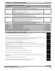
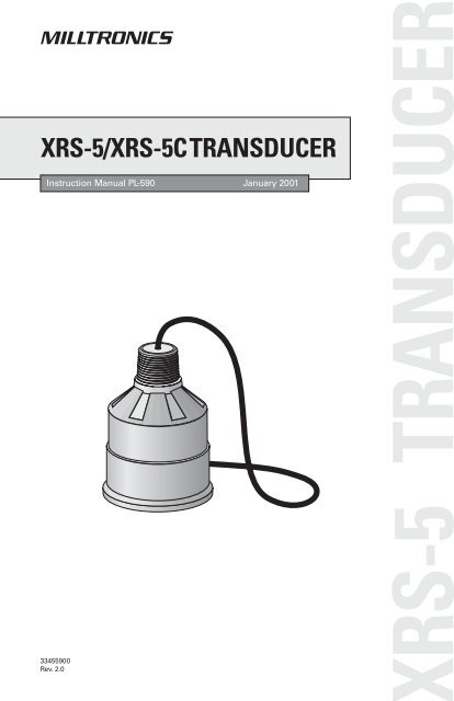
<strong>XRS</strong>-5/<strong>XRS</strong>-<strong>5C</strong>TRANSDUCER<br />
Instruction Manual PL-590 January 2001<br />
33455900<br />
Rev. 2.0<br />
RS-5 TRANSDUCER
Safety Guidelines<br />
Warning notices must be observed to ensure personal safety as well as that of others, and to<br />
protect the product and the connected equipment. These warning notices are accompanied<br />
by a clarification of the level of caution to be observed.<br />
Qualified Personnel<br />
This device/system may only be set up and operated in conjunction with this manual.<br />
Qualified personnel are only authorized to install and operate this equipment in accordance<br />
with established safety practices and standards.<br />
Warning: This product can only function properly and safely if it is correctly transported,<br />
stored, installed, set up, operated, and maintained.<br />
Note: Always use product in accordance with specifications.<br />
Copyright <strong>Siemens</strong> <strong>Milltronics</strong> Process<br />
Instruments Inc. 2000. All Rights Reserved<br />
This document is available in bound version and in<br />
electronic version. We encourage users to<br />
purchase authorized bound manuals, or to view<br />
electronic versions as designed and authored by<br />
<strong>Siemens</strong> <strong>Milltronics</strong> Process Instruments Inc.<br />
<strong>Siemens</strong> <strong>Milltronics</strong> Process Instruments Inc. will<br />
not be responsible for the contents of partial or<br />
whole reproductions of either bound or electronic<br />
versions.<br />
© <strong>Siemens</strong> <strong>Milltronics</strong> Process Instruments Inc. 2001<br />
Disclaimer of Liability<br />
While we have verified the contents of<br />
this manual for agreement with the<br />
instrumentation described, variations<br />
remain possible. Thus we cannot<br />
guarantee full agreement. The<br />
contents of this manual are regularly<br />
reviewed and corrections are included<br />
in subsequent editions. We welcome<br />
all suggestions for improvement.<br />
Technical data subject to change.<br />
MILLTRONICS®is a registered trademark of <strong>Siemens</strong> <strong>Milltronics</strong> Process Instruments Inc.<br />
Contact SMPI Technical Publications at the following address:<br />
Technical Publications<br />
<strong>Siemens</strong> <strong>Milltronics</strong> Process Instruments Inc.<br />
1954 Technology Drive, P.O. Box 4225<br />
Peterborough, Ontario, Canada, K9J 7B1<br />
Email: techpubs@milltronics.com<br />
For the library of SMPI instruction manuals, visit our Web site: www.milltronics.com
Table of Contents<br />
Table of Contents ....................................................................................3<br />
Specifications .........................................................................................5<br />
About the <strong>Transducer</strong>..............................................................................7<br />
General Guidelines .............................................................................8<br />
Installation ...............................................................................................9<br />
Outline and Dimensions ......................................................................9<br />
Mounting................................................................................................11<br />
Recommendations............................................................................11<br />
Applications...........................................................................................13<br />
Open Channel Meter.........................................................................13<br />
Standpipes and Stilling Wells.............................................................14<br />
Water / Wastewater...........................................................................15<br />
<strong>Transducer</strong> Placement ......................................................................16<br />
Locations..........................................................................................16<br />
Interconnection .....................................................................................19<br />
Direct Connection .............................................................................19<br />
Coaxial Connection ...........................................................................20<br />
2-Wire Extension (for EnviroRanger ERS 500 only)............................20<br />
Maintenance ..........................................................................................20<br />
Installation Diagram for <strong>XRS</strong>-5 ..............................................................21<br />
Installation Diagram for <strong>XRS</strong>-<strong>5C</strong>............................................................22<br />
PL-590 <strong>XRS</strong>-5 <strong>Transducer</strong> Page 3
Page 4 <strong>XRS</strong>-5 <strong>Transducer</strong> PL-590
Specifications<br />
Process Application: liquids and slurries<br />
<br />
<br />
Measurement Range 0.3 to 8m (1 - 26 ft) typical (application variables apply)<br />
Vessel Pressure vented to atmosphere<br />
Operation:<br />
<br />
<br />
<br />
Beam Angle 10°<br />
Frequency 43 KHz<br />
Temperature Sensor internal<br />
<br />
<br />
<br />
<br />
Supply Source<br />
Environmental:<br />
transducer shall only be supplied by <strong>Milltronics</strong> certified<br />
controller<br />
Location indoor / outdoor<br />
Ambient temperatures -20 to 65 °C (-4 to 149 °F)<br />
Altitude 2000 m maximum<br />
Pollution degree 4<br />
<br />
Construction:<br />
Housing Kynar Flex ®1<br />
body and Hypalon ®2<br />
face<br />
<strong>XRS</strong>-<strong>5C</strong> has SS conduit connection<br />
<br />
Cable:<br />
Mounting <strong>XRS</strong>-5: 1” NPT or BSP conduit connection<br />
Ingress protection:<br />
IP-68<br />
2 wire shielded / twisted, 0.5 mm 2<br />
Weight 3<br />
:<br />
1.2 Kg (2.6 lb)<br />
Options:<br />
<strong>XRS</strong>-<strong>5C</strong>: 1” NPT<br />
(18 AWG) PVC jacket<br />
factory flanged to suit ANSI , DIN or JIS standard<br />
<br />
split flange (field mount) to suit ANSI, DIN or JIS standard<br />
<br />
submergence shield (flooding applications)<br />
Cabling (maximum run):<br />
365 m (1200 ft) using RG-62 A/U coaxial cable<br />
<br />
365 m (1200 ft) using 2-wire twisted pair / braided and foil shielded 20 AWG (0.5<br />
<br />
mm 2 ), PVC jacket (EnviroRanger ERS 500 only)<br />
Approvals:<br />
<strong>XRS</strong>-5: CE 4<br />
, CSA, FM, CENELEC/ATEX, SAA, see device nameplate<br />
O <strong>XRS</strong>-<strong>5C</strong>: CSA<br />
O Please verify against the device nameplate<br />
1<br />
Kynar Flex ® is registered trademark of ELF Atochem.<br />
2<br />
Hypalon ®<br />
is a registered trademark of Du Pont<br />
3<br />
approximate weight of transducer with standard cable length<br />
4<br />
EMC performance available upon request<br />
PL-590 <strong>XRS</strong>-5 <strong>Transducer</strong> Page 5<br />
Specifications
Specifications<br />
Page 6 <strong>XRS</strong>-5 <strong>Transducer</strong> PL-590
About the <strong>Transducer</strong><br />
The Echomax <strong>XRS</strong>-5 transducer works with <strong>Milltronics</strong> transceivers and<br />
provides the ultrasonic pulse and echo reception<br />
that these devices require.<br />
The transducer converts electrical pulses<br />
provided by the transceiver to ultrasonic pulses<br />
used for measurement and then converts the<br />
ultrasonic echoes back to an electrical signal.<br />
This signal is interpreted by the <strong>Milltronics</strong><br />
tranceiver using the patented Sonic<br />
Intelligence algorithms. The ultrasonic pulse<br />
reduces in power by 3dB in a 10° cone from the<br />
transducer face. It is important to keep objects<br />
out of this cone to reduce the chance of false<br />
echos being recorded.<br />
The <strong>XRS</strong>-5 transducer incorporates an<br />
integral temperature sensor that reports the<br />
ambient temperature to the transceiver. The<br />
connection is transparent in that both the<br />
ultrasonic and temperature components of<br />
the transducer use the same leads. This<br />
ensures that the <strong>Milltronics</strong> transceiver can<br />
automatically compensate the speed of<br />
sound constant for varying temperatures.<br />
transducer<br />
transducer<br />
face<br />
-3db<br />
boundary<br />
axis of<br />
transmission,<br />
perpendicular<br />
to transducer<br />
face<br />
PL-590 <strong>XRS</strong>-5 <strong>Transducer</strong> Page 7<br />
About this …
About this …<br />
General Guidelines<br />
The equipment may be used in all hazardous zones with all gases with<br />
temperature classes T1, T2, T3, T4, T5 and T6. The equipment is only<br />
certified for use in ambient temperatures in the range of -20°C to +65°C and<br />
should not be used outside this range.<br />
• Installation shall be carried out in accordance with the applicable code of<br />
practice by suitably trained personnel.<br />
• The apparatus shall only be supplied from a circuit containing a suitablyrated<br />
fuse having a breaking capacity of 4000A. This fuse is included in<br />
<strong>Milltronics</strong>’ transceivers.<br />
• Repair of this equipment shall be carried out in accordance with the<br />
applicable code of practice.<br />
• The certification of this equipment relies on the following materials used in its<br />
construction:<br />
Enclosure: Kynar Flex 2800-02 (former designation 2820) /<br />
Chlorosulfonated polyethylene / Nitrile / Ethylene propylene<br />
/ Chloroprene<br />
Encapsulant: LA-9823-76<br />
• Manual override can be accomplished by using the disconnect switch<br />
provided in the building installation of the associated controller.<br />
Page 8 <strong>XRS</strong>-5 <strong>Transducer</strong> PL-590
Installation<br />
Outline and Dimensions<br />
Standard Flange (optional)<br />
89mm<br />
(3.5”)<br />
Submergence Shield Split Flange (optional)<br />
124mm<br />
(4.9”)<br />
127mm<br />
(5.0”)<br />
155mm<br />
(6.1”)<br />
Refer to <strong>Milltronics</strong><br />
instruction manual PL-530.<br />
ANSI, DIN or JIS<br />
standards<br />
ANSI, DIN or JIS<br />
standards<br />
127mm<br />
(5.0”)<br />
133mm<br />
(5.2”)<br />
nominal<br />
PL-590 <strong>XRS</strong>-5 <strong>Transducer</strong> Page 9<br />
Installation
Installation<br />
Page 10 <strong>XRS</strong>-5 <strong>Transducer</strong> PL-590
Mounting<br />
Recommendations<br />
• Mount the transducer so that it is above the maximum material level by more<br />
than the blanking value to ensure that accurate results are achieved. Refer<br />
to the associated transceiver manual for information on setting the blanking<br />
value.<br />
• The transducer must be mounted so that the axis of transmission is<br />
perpendicular to the liquid’s surface.<br />
• Do not over tighten mounting. Hand tightening of the mounting hardware is<br />
sufficient.<br />
• Consider the optional temperature sensor when mounting the transducer.<br />
Suspended Conduit Bracket<br />
rigid metal<br />
conduit<br />
coupling<br />
Flexible conduit transducer should not be<br />
subjected to wind, vibration or jarring.<br />
Submersible Plywood<br />
rigid metal<br />
conduit<br />
coupling<br />
Submersible transducer, used in<br />
applications where flooding is possible.<br />
transducer<br />
submergence<br />
shield<br />
flexible conduit<br />
steel channel<br />
coupling<br />
coupling<br />
Plywood mounting provides excellent<br />
isolation, but must be rigid enough to<br />
avoid flexing if subjected to loading.<br />
PL-590 <strong>XRS</strong>-5 <strong>Transducer</strong> Page 11<br />
Mounting
Mounting<br />
Blind Flange<br />
Face Flange<br />
nipple welded<br />
to bind flange<br />
coupling<br />
coupling<br />
factory flanged<br />
transducer<br />
Note:<br />
Tighten the flange bolts evenly in order to ensure a good seal between the<br />
mating flanges.<br />
Caution: Over tightening can cause performance degradation.<br />
Page 12 <strong>XRS</strong>-5 <strong>Transducer</strong> PL-590<br />
bolt<br />
gasket<br />
customer flanged,<br />
flat face only<br />
nut
Applications<br />
Notes:<br />
• The transducer is to be used only in the manner outlined in this<br />
instruction manual.<br />
• This transducer requires no maintenance, and is recommended for use<br />
with liquids only.<br />
• The OCM III requires the use of the TS-2 external temperature sensor.<br />
The internal temperature sensor in the <strong>XRS</strong>-5 cannot be used.<br />
Open Channel Meter<br />
typical flume or weir<br />
Refer to OCM manufacturer specification for proper point of head<br />
measurement.<br />
refer to <strong>Milltronics</strong><br />
transceiver manual for<br />
minimum distance above<br />
maximum head.<br />
The OCM III requires the use of the TS-2 external temperature sensor<br />
instead of the <strong>XRS</strong>-5 internal temperature sensor. The use of an external<br />
temperature sensor provides better temperature tracking in applications<br />
where the temperature can change quickly.<br />
PL-590 <strong>XRS</strong>-5 <strong>Transducer</strong> Page 13<br />
Applications
Applications<br />
Standpipes and Stilling Wells<br />
In many applications, access must be made via a standpipe. In such cases,<br />
<strong>Milltronics</strong> can provide factory flanged transducers or split flange kit that will<br />
readily mate to the flanged standpipe. Another option is to hang the<br />
transducer from a blind flange.<br />
The standpipe length should be as short and the diameter as large as<br />
possible. As a rule of thumb, the -3 dB cone of the sound beam should not<br />
intersect the standpipe wall in applications opening into a vessel or larger<br />
area. Otherwise, additional blanking will be required to compensate for the<br />
interference zone created by the opening.<br />
Note: When using a stilling well, make sure there is no build-up, welds, couplings,<br />
or other debris on the inside of the well wall. This can affect reliability of level<br />
measurement.<br />
vessel<br />
no additional blanking required no additional blanking required<br />
transducer<br />
can read<br />
level inside<br />
or below<br />
standpipe<br />
no additional blanking required<br />
flanged<br />
transducer<br />
no<br />
intersection<br />
blind flange<br />
mounting<br />
standpipe<br />
end cut on a<br />
45° angle<br />
typically<br />
vessel<br />
no<br />
vessel<br />
vent<br />
blind flange<br />
mounting<br />
transducer<br />
sound beam<br />
intersects<br />
reflection at<br />
interference<br />
zone created<br />
by opening<br />
near blanking extension of 150 mm (6”)<br />
past end of standpipe may be required.<br />
Page 14 <strong>XRS</strong>-5 <strong>Transducer</strong> PL-590
Water / Wastewater<br />
Differential Level<br />
Pump Control<br />
Sewage Lift<br />
PL-590 <strong>XRS</strong>-5 <strong>Transducer</strong> Page 15<br />
Applications
Applications<br />
<strong>Transducer</strong> Placement<br />
The following graphic shows the best placement of the <strong>XRS</strong>-5 transducer.<br />
Maintain full fluid<br />
level for full or<br />
offset calibration.<br />
Do not allow<br />
material to enter<br />
blanking zone.<br />
Empty level for ‘B’<br />
location. Below this<br />
level, echo would<br />
reflect away from<br />
the transducer.<br />
Locations<br />
‘B’ ‘A’ ‘C’<br />
beam<br />
angle<br />
A. Primary location. This is the preferred location and should be used<br />
whenever possible. The centre of the tank generally gives the most reliable<br />
readings because there are fewer obstructions to provide false echos.<br />
B. Alternate location. This location is used if the centre of the tank is already<br />
in use or if the tank roof is too weak to hold the transducer safely.<br />
C. Poor location. This is a poor installation location. The echos are shown<br />
reflecting away from the transducer face.<br />
rise<br />
may require target to<br />
obtain empty reading discharge<br />
span:<br />
distance between<br />
Empty and Full<br />
levels in the<br />
measured process<br />
tank<br />
manufacturer’s<br />
empty level<br />
Page 16 <strong>XRS</strong>-5 <strong>Transducer</strong> PL-590<br />
run
Notes<br />
1. Beam should not detect bin bottom.<br />
If this occurs, use range extension parameters (on<br />
transceivers where available) to omit false echoes.<br />
The <strong>XRS</strong>-5 transducer operates with a beam<br />
angle of 10° and has a rise:run ratio of<br />
approximately 12:1. This means that for every 1m<br />
(3.3’) of tank height, the transducer projects a<br />
circular area over the material surface with a<br />
radius of 83mm (32.7”). In most tanks the<br />
transducer should be centred as much as<br />
possible (without interference from inlet) for<br />
optimum reading range.<br />
2. Sound beam must be perpendicular to<br />
83mm<br />
liquid surface.<br />
When mounting the standpipe and flange you must ensure that the<br />
transducer face will be parallel with the liquid’s surface.<br />
3. Echo has missed an improperly levelled transducer.<br />
As 2, ensure that the standpipe and flange are mounted to set the<br />
transducer face level with the measured liquid.<br />
4. Calibrate under normal conditions.<br />
When performing an empty or full calibration, the tank must contain its<br />
normal vapour and be at its normal temperature.<br />
PL-590 <strong>XRS</strong>-5 <strong>Transducer</strong> Page 17<br />
1m<br />
Applications
Applications<br />
Page 18 <strong>XRS</strong>-5 <strong>Transducer</strong> PL-590
Interconnection<br />
Note:<br />
Installation shall only be performed by qualified personnel and in<br />
accordance with local governing regulations.<br />
Dos and Don’ts<br />
For best results follow these installation rules:<br />
• Do not route cable openly, instead run cable separately in a grounded metal<br />
conduit to protect it from ambient electrical noise.<br />
• Seal all thread connections to prevent the ingress of moisture.<br />
• Do not run cable near high voltage or current runs, contactors or SCR<br />
control drives.<br />
In all of the following examples the terminal blocks on the transceiver are<br />
described in the transceiver manual.<br />
Direct Connection<br />
Connect the transducer directly to the <strong>Milltronics</strong> transceiver via the 2<br />
conductor shielded cable.<br />
Note:<br />
When connecting to an EnviroRanger ERS 500, the white, black, and<br />
shield wires are all connected separately. Do not tie the white and shield<br />
wires together.<br />
PL-590 <strong>XRS</strong>-5 <strong>Transducer</strong> Page 19<br />
blk<br />
wht<br />
drain / shield<br />
Interconnection
Interconnection<br />
Coaxial Connection<br />
Connect the transducer to the <strong>Milltronics</strong> transceiver via a junction box and<br />
RG–62 A/U coaxial cable. This setup is effective for combined runs up to<br />
365m (1200’).<br />
Note:<br />
When connecting to an EnviroRanger ERS 500, do NOT use coaxial<br />
cable, see diagram below for proper procedure.<br />
2-Wire Extension (for EnviroRanger ERS 500 only)<br />
Maintenance<br />
wht<br />
Normally, no maintenance is required on the transducer.<br />
extend cable using<br />
RG – 62 A/U coax<br />
However, if performance changes are observed, immediately shut down the<br />
level measurement system and perform a thorough inspection, especially on<br />
the transducer.<br />
Page 20 <strong>XRS</strong>-5 <strong>Transducer</strong> PL-590<br />
blk<br />
junction box<br />
drain / shield<br />
extend cable using 18 AWG<br />
shielded / twisted pair
Installation Diagram for <strong>XRS</strong>-5<br />
PL-590 <strong>XRS</strong>-5 <strong>Transducer</strong> Page 21<br />
Installation Diagram
Installation Diagram<br />
Installation Diagram for <strong>XRS</strong>-<strong>5C</strong><br />
Page 22 <strong>XRS</strong>-5 <strong>Transducer</strong> PL-590
*7ml19981bj01*