The Invention and Development of the Radiosonde - Smithsonian ...
The Invention and Development of the Radiosonde - Smithsonian ...
The Invention and Development of the Radiosonde - Smithsonian ...

Create successful ePaper yourself
Turn your PDF publications into a flip-book with our unique Google optimized e-Paper software.
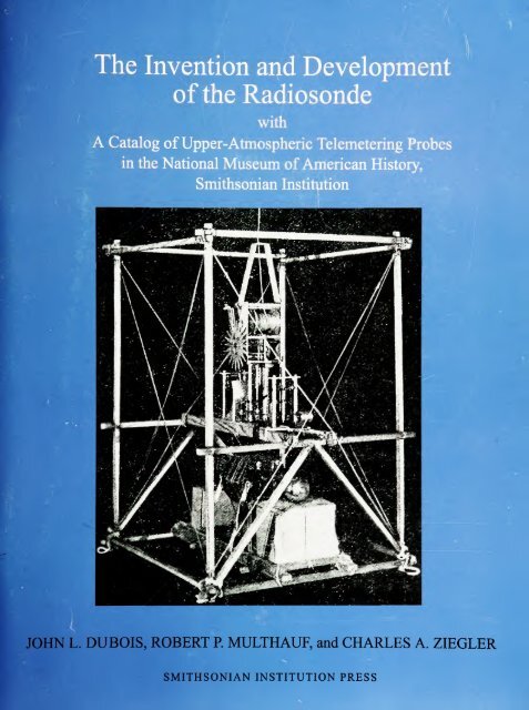
<strong>The</strong> <strong>Invention</strong> <strong>and</strong> <strong>Development</strong><br />
<strong>of</strong> <strong>the</strong> <strong>Radiosonde</strong><br />
with<br />
A Catalog <strong>of</strong> Upper-Atmospheric Telemetering Probes<br />
in <strong>the</strong> National Museum <strong>of</strong> American History,<br />
<strong>Smithsonian</strong> Institution<br />
JOHN L. DUBOIS, ROBERT P. MULTHAUF, <strong>and</strong> CHARLES A. ZIEGLER<br />
SMITHSONIAN INSTITUTION PRESS
SERIES PUBLICATIONS OF THE SMITHSONIAN INSTITUTION<br />
Emphasis upon publication as a means <strong>of</strong> "diffusing knowledge" was expressed by <strong>the</strong> first<br />
Secretary <strong>of</strong> <strong>the</strong> <strong>Smithsonian</strong>. In his formal plan for <strong>the</strong> Institution, Joseph Henry outlined a<br />
program that included <strong>the</strong> following statement: "It is proposed to publish a series <strong>of</strong> reports,<br />
giving an account <strong>of</strong> <strong>the</strong> new discoveries in science, <strong>and</strong> <strong>of</strong> <strong>the</strong> changes made from year to year<br />
in all branches <strong>of</strong> knowledge." This <strong>the</strong>me <strong>of</strong> basic research has been adhered to through <strong>the</strong><br />
years by thous<strong>and</strong>s <strong>of</strong> titles issued in series publications under <strong>the</strong> <strong>Smithsonian</strong> imprint,<br />
commencing with <strong>Smithsonian</strong> Contributions to Knowledge in 1848 <strong>and</strong> continuing with <strong>the</strong><br />
following active series:<br />
<strong>Smithsonian</strong> Contributions to Anthropology<br />
<strong>Smithsonian</strong> Contributions to Botany<br />
<strong>Smithsonian</strong> Contributions to <strong>the</strong> Earth Sciences<br />
<strong>Smithsonian</strong> Contributions to <strong>the</strong> Marine Sciences<br />
<strong>Smithsonian</strong> Contributions to Paleobiology<br />
<strong>Smithsonian</strong> Contributions to Zoology<br />
<strong>Smithsonian</strong> Folklife Studies<br />
<strong>Smithsonian</strong> Studies in Air <strong>and</strong> Space<br />
<strong>Smithsonian</strong> Studies in History <strong>and</strong> Technology<br />
In <strong>the</strong>se series, <strong>the</strong> Institution publishes small papers <strong>and</strong> full-scale monographs that report<br />
<strong>the</strong> research <strong>and</strong> collections <strong>of</strong> its various museums <strong>and</strong> bureaux or <strong>of</strong> pr<strong>of</strong>essional colleagues<br />
in <strong>the</strong> world <strong>of</strong> science <strong>and</strong> scholarship. <strong>The</strong> publications are distributed by mailing lists to<br />
libraries, universities, <strong>and</strong> similar institutions throughout <strong>the</strong> world.<br />
Papers or monographs submitted for series publication are received by <strong>the</strong> <strong>Smithsonian</strong><br />
Institution Press, subject to its own review for format <strong>and</strong> style, only through departments <strong>of</strong> <strong>the</strong><br />
various <strong>Smithsonian</strong> museums or bureaux, where <strong>the</strong> manuscripts are given substantive review.<br />
Press requirements for manuscript <strong>and</strong> art preparation are outlined on <strong>the</strong> inside back cover.<br />
Lawrence M. Small<br />
Secretary<br />
<strong>Smithsonian</strong> Institution
SMITHSONIAN STUDIES IN HISTORY AND TECHNOLOGY • NUMBER 53<br />
<strong>The</strong> <strong>Invention</strong> <strong>and</strong> <strong>Development</strong><br />
<strong>of</strong> <strong>the</strong> <strong>Radiosonde</strong>, with a Catalog<br />
<strong>of</strong> Upper-Atmospheric Telemetering Probes<br />
in <strong>the</strong> National Museum <strong>of</strong> American History,<br />
<strong>Smithsonian</strong> Institution<br />
John L. DuBois, Robert P. Multhauf,<br />
<strong>and</strong> Charles A. Ziegler<br />
<strong>Smithsonian</strong> Institution Press<br />
Washington, D.C.<br />
2002
ABSTRACT<br />
DuBois, John L., Robert P. Multhauf, <strong>and</strong> Charles A. Ziegler. <strong>The</strong> <strong>Invention</strong> <strong>and</strong> <strong>Development</strong><br />
<strong>of</strong> <strong>the</strong> <strong>Radiosonde</strong>, with a Catalog <strong>of</strong> Upper-Atmospheric Telemetering Probes in <strong>the</strong><br />
National Museum <strong>of</strong> American History, <strong>Smithsonian</strong> Institution. <strong>Smithsonian</strong> Studies in History<br />
<strong>and</strong> Technology, number 53, 78 pages, 60 figures, 2002.—From a historical perspective,<br />
<strong>the</strong> radiosonde is one <strong>of</strong> <strong>the</strong> more significant technological innovations <strong>of</strong> <strong>the</strong> twentieth century,<br />
not only because its widespread use greatly enhanced <strong>the</strong> accuracy <strong>of</strong> wea<strong>the</strong>r forecasting,<br />
but also because some features <strong>of</strong> its basic design became <strong>the</strong> foundation <strong>of</strong> all modern analog<br />
telemetry systems. This study examines <strong>the</strong> way in which advances in <strong>the</strong> technology <strong>of</strong> nontelemetering<br />
balloonsondes <strong>and</strong> radio in <strong>the</strong> nineteenth <strong>and</strong> twentieth centuries culminated in<br />
<strong>the</strong> invention <strong>of</strong> <strong>the</strong> radiosonde in 1929. <strong>The</strong> subsequent development <strong>of</strong> radiosondes in Europe<br />
<strong>and</strong> <strong>the</strong> United States from 1929 to 1940 is traced in detail, when <strong>the</strong> basic design <strong>of</strong> this instrument<br />
achieved its modern form. An overview <strong>of</strong> significant modifications in radiosonde design<br />
after 1940 also is provided because <strong>the</strong> instruments have remained an essential meteorological<br />
tool in <strong>the</strong> twenty-first century. This monograph also includes a catalog <strong>of</strong> radiosondes in <strong>the</strong><br />
<strong>Smithsonian</strong> Institution's National Museum <strong>of</strong> American History. Photographs <strong>of</strong> instruments<br />
in this unique collection that graphically depict <strong>the</strong> development stages <strong>of</strong> <strong>the</strong> radiosonde are<br />
presented.<br />
OFFICIAL PUBLICATION DATE is h<strong>and</strong>stamped in a limited number <strong>of</strong> initial copies <strong>and</strong> is recorded in <strong>the</strong><br />
Institution's annual report, Annals <strong>of</strong> <strong>the</strong> <strong>Smithsonian</strong> Institution. COVER DESIGN: <strong>The</strong> first true radiosonde,<br />
which was flown by Robert Bureau in 1929.<br />
Library <strong>of</strong> Congress Cataloging-in-Publication Data<br />
DuBois, John L.<br />
<strong>The</strong> invention <strong>and</strong> development <strong>of</strong> <strong>the</strong> radiosonde : with a catalog <strong>of</strong> upper-atmospheric telemetering probes in<br />
<strong>the</strong> National Museum <strong>of</strong> American History, <strong>Smithsonian</strong> Institution / John L. DuBois, Robert P. Multhauf, <strong>and</strong><br />
Charles A. Ziegler.<br />
p. cm.—(<strong>Smithsonian</strong> studies in history <strong>and</strong> technology ; no. 53)<br />
Includes bibliographical references.<br />
1. <strong>Radiosonde</strong>s—History—19th Century. 2. <strong>Radiosonde</strong>s—History—20th century. 3. <strong>Radiosonde</strong>s—<br />
Catalogs. 4. National Museum <strong>of</strong> American History (U.S.)—Catalogs. I. Multhauf, Robert<br />
P. II. Ziegler, Charles A. (Charles Albert), 1927- III. Title. IV. Series.<br />
QC879.25.D83 2002 551.63'52—dc21 2002030658<br />
© <strong>The</strong> paper used in this publication meets <strong>the</strong> minimum requirements <strong>of</strong> <strong>the</strong> American<br />
National St<strong>and</strong>ard for Permanence <strong>of</strong> Paper for Printed Library Materials Z39.48—1984.
Contents<br />
Page<br />
Preface iv<br />
Introduction 1<br />
I. THE PROBLEM OF HIGH-ALTITUDE METEOROLOGY AND THE TECHNOLOGY<br />
THAT LED TO THE RADIOSONDE<br />
1. Nontelemetering Balloonsondes, 1892-1929 3<br />
2. Preradio Telemetering, 1842-1894 15<br />
3. Radio Telemetry, 1895-1929 19<br />
II. THE RADIOSONDE: DEVELOPMENT AND APPLICATION<br />
4. <strong>The</strong> Early Years, 1921-1928 26<br />
5. <strong>The</strong> Prototypes, 1929-1930 30<br />
6. Maturity, 1931-1940 41<br />
7. <strong>The</strong> <strong>Radiosonde</strong> after 1940 59<br />
8. Conclusion 67<br />
III. CATALOG OF UPPER-ATMOSPHERIC TELEMETERING PROBES AND RELATED<br />
ARTIFACTS IN THE NATIONAL MUSEUM OF AMERICAN HISTORY,<br />
SMITHSONIAN INSTITUTION<br />
Notes 73<br />
Appendix: Selected United States Patents Related to <strong>Radiosonde</strong>s 75<br />
Literature Cited 76<br />
in
Preface<br />
"<strong>Radiosonde</strong>" is a balloon-borne instrument that transmits atmospheric data, usually<br />
temperature, pressure, <strong>and</strong> humidity, to a receiver-recorder on <strong>the</strong> ground. <strong>The</strong> contributions<br />
<strong>of</strong> this relatively simple device to <strong>the</strong> late twentieth-century way <strong>of</strong> life can hardly be<br />
exaggerated. No o<strong>the</strong>r factor contributed more to <strong>the</strong> systematization <strong>of</strong> wea<strong>the</strong>r observations,<br />
which is beneficial to all who depend upon meteorological prediction. <strong>The</strong> utilization<br />
<strong>of</strong> <strong>the</strong> radiosonde directly affected agriculture <strong>and</strong> aeronautics, <strong>and</strong> its more sophisticated<br />
<strong>of</strong>fspring made possible many <strong>of</strong> <strong>the</strong> marvels <strong>of</strong> <strong>the</strong> space age.<br />
<strong>The</strong> collection <strong>of</strong> instruments on which this study is based was assembled throughout a<br />
decade <strong>and</strong> a half, 1955-1970, as part <strong>of</strong> <strong>the</strong> program <strong>of</strong> <strong>the</strong> <strong>Smithsonian</strong> Institution to establish<br />
a new museum <strong>of</strong> <strong>the</strong> history <strong>of</strong> science <strong>and</strong> technology <strong>and</strong> <strong>of</strong> <strong>the</strong> political <strong>and</strong> social<br />
history <strong>of</strong> <strong>the</strong> United States.<br />
A museum rarely exhibits its entire collection in any field at one time, <strong>and</strong> objects not<br />
exhibited are retained for reference purposes. In <strong>the</strong> latter function, nothing is more useful<br />
than a printed catalog. Because <strong>of</strong> <strong>the</strong> variety <strong>of</strong> museum collections, <strong>the</strong> production <strong>of</strong><br />
such catalogs is only occasionally realized. Such a document is most important when <strong>the</strong><br />
collection in question is uncommon, or even unique. This may be <strong>the</strong> case with <strong>the</strong> collection<br />
described herein.<br />
Because "old" scientific instruments <strong>of</strong>ten are unfamiliar even to those who use modem<br />
instruments serving <strong>the</strong> same, or similar, purposes, some guidance in <strong>the</strong>ir construction<br />
<strong>and</strong> functions is useful. It also is important to underst<strong>and</strong> that <strong>the</strong> history <strong>of</strong> a scientific instrument<br />
is a case history in <strong>the</strong> process <strong>of</strong> invention. For <strong>the</strong>se reasons, this publication<br />
includes a capsule history <strong>of</strong> <strong>the</strong> development <strong>of</strong> <strong>the</strong> radiosonde based upon <strong>the</strong> instruments<br />
<strong>the</strong>mselves <strong>and</strong> upon <strong>the</strong> original literature connected with <strong>the</strong>ir development.<br />
We are particularly indebted to Robert Wright <strong>of</strong> <strong>the</strong> Instrument Division <strong>of</strong> <strong>the</strong> United<br />
States Wea<strong>the</strong>r Bureau, who thought old instruments worth collecting, <strong>and</strong> to Christon<br />
Harmantas, who knew what <strong>the</strong>y were. George A. Norton, Jr., assisted greatly with <strong>the</strong> catalog<br />
<strong>of</strong> specimens.<br />
We also gratefully acknowledge <strong>the</strong> help <strong>of</strong> William Blair, Jr., who kindly supplied us<br />
with copies <strong>of</strong> selected published <strong>and</strong> unpublished documents from <strong>the</strong> collected papers <strong>of</strong><br />
his fa<strong>the</strong>r, Colonel William Blair. Thanks also are due H.C. McBrair who alerted us to <strong>the</strong><br />
importance <strong>of</strong> Colonel Blair's research to <strong>the</strong> early history <strong>of</strong> <strong>the</strong> radiosonde <strong>and</strong> who<br />
shared with us his reminiscences <strong>of</strong> radiosonde development at Wallace <strong>and</strong> Tiernan Inc.,<br />
an early manufacturer <strong>of</strong> radiosonde equipment. At <strong>the</strong> opposite end <strong>of</strong> <strong>the</strong> time-span with<br />
which we are concerned, we are indebted for <strong>the</strong> support <strong>of</strong> <strong>the</strong> following historians at <strong>the</strong><br />
<strong>Smithsonian</strong> Institution: David Devorkin <strong>of</strong> <strong>the</strong> National Air <strong>and</strong> Space Museum <strong>and</strong> Deborah<br />
Warner <strong>of</strong> <strong>the</strong> National Museum <strong>of</strong> American History.<br />
IV<br />
Robert P. Multhauf<br />
Director Emeritus<br />
National Museum <strong>of</strong> American History<br />
<strong>Smithsonian</strong> Institution
<strong>The</strong> <strong>Invention</strong> <strong>and</strong> <strong>Development</strong><br />
<strong>of</strong> <strong>the</strong> <strong>Radiosonde</strong>, with a Catalog<br />
<strong>of</strong> Upper-Atmospheric Telemetering Probes<br />
in <strong>the</strong> National Museum <strong>of</strong> American History,<br />
<strong>Smithsonian</strong> Institution<br />
John L. DuBois, Robert P. Multhauf,<br />
<strong>and</strong> Charles A. Ziegler<br />
Introduction<br />
<strong>The</strong> collection <strong>and</strong> transmission <strong>of</strong> data is as old as <strong>the</strong> hu made to develop meteorological instruments that automatically<br />
man species. Information about <strong>the</strong> wea<strong>the</strong>r may have first recorded <strong>the</strong>ir readings. Steady improvements were made in<br />
achieved "scientific" status when sensible observation (e.g., <strong>the</strong> data collection process, but it soon was recognized that it<br />
coldest winter in <strong>the</strong> memory <strong>of</strong> <strong>the</strong> oldest resident) <strong>of</strong> meteo was even more important to devise some speedy method for<br />
rological data was augmented by instruments capable <strong>of</strong> nu transmitting <strong>the</strong> data from various collection points to a central<br />
merically describing <strong>the</strong> elements <strong>of</strong> <strong>the</strong> wea<strong>the</strong>r.<br />
bureau. One means to accomplish this task existed in <strong>the</strong> eigh<br />
<strong>The</strong> invention, in <strong>the</strong> seventeenth century, <strong>of</strong> <strong>the</strong> <strong>the</strong>rmometeenth century. <strong>The</strong> visual telegraph, which used lanterns <strong>and</strong><br />
ter, barometer, hygrometer, <strong>and</strong> wind speed <strong>and</strong> direction indi mechanized semaphores, was invented in 1794 by a French <strong>of</strong>cators,<br />
was a phenomenon <strong>of</strong> <strong>the</strong> scientific revolution. <strong>The</strong>se ficer, Claude Chappe. Its primary purpose was to improve mili<br />
were hardly comparable in importance with some o<strong>the</strong>r inventary communications, but because wea<strong>the</strong>r conditions were <strong>of</strong><br />
tions <strong>of</strong> <strong>the</strong> time, such as <strong>the</strong> telescope, whose revelations spec vital military importance, both <strong>the</strong> collection <strong>and</strong> transmission<br />
tacularly embellished astronomy, <strong>the</strong> already crowned "queen" <strong>of</strong> meteorological data increasingly were made ancillary to <strong>the</strong><br />
<strong>of</strong> <strong>the</strong> sciences. Astronomy already was ma<strong>the</strong>maticized,<br />
whereas <strong>the</strong> "science" <strong>of</strong> <strong>the</strong> meteorologist still was difficult to<br />
distinguish from <strong>the</strong> art <strong>of</strong> <strong>the</strong> occultist. Still, instruments <strong>and</strong><br />
<strong>the</strong> numerical recording <strong>of</strong> data gave hope for scientific respectability,<br />
<strong>and</strong>, by <strong>the</strong> end <strong>of</strong> <strong>the</strong> eighteenth century, <strong>the</strong> collection<br />
<strong>of</strong> meteorological data was one <strong>of</strong> <strong>the</strong> principle concerns<br />
<strong>of</strong> <strong>the</strong> numerous scientific societies that were part <strong>of</strong> <strong>the</strong><br />
scientific revolution. <strong>The</strong>ir periodical publications, <strong>the</strong> first <strong>of</strong><br />
which was established in <strong>the</strong> 1660s, were devoted primarily to<br />
<strong>the</strong> dissemination <strong>of</strong> meteorological information.<br />
military art. In <strong>the</strong> United States, <strong>the</strong> army played a key role in<br />
both <strong>the</strong> collection <strong>and</strong> <strong>the</strong> transmission <strong>of</strong> meteorological data<br />
via <strong>the</strong> electromagnetic telegraph, which was introduced in <strong>the</strong><br />
1840s.<br />
Yet, by <strong>the</strong> early twentieth century, <strong>the</strong> transmission <strong>of</strong> meteorological<br />
data still was a minor application <strong>of</strong> <strong>the</strong> electromagnetic<br />
telegraph. <strong>The</strong> introduction <strong>of</strong> <strong>the</strong> wireless telegraph (radio)<br />
did little to change this, although experiments in <strong>the</strong><br />
automatic transmission <strong>of</strong> data from remote meteorological instruments,<br />
including <strong>the</strong> transmission by wire from balloons,<br />
By <strong>the</strong> end <strong>of</strong> <strong>the</strong> seventeenth century, attempts had been continued until <strong>the</strong> 1920s, when radio transmission was<br />
adopted.<br />
<strong>The</strong>re were logical reasons for this lack <strong>of</strong> progress. <strong>The</strong> ac<br />
John L. DuBois, C.E.O. <strong>The</strong>rmalogic Corporation, Hudson, Massacumulated<br />
mass <strong>of</strong> meteorological data had not greatly imchusetts,<br />
01749. Robert P. Multhauf, Director Emeritus, National Museum<br />
<strong>of</strong>Americam History, <strong>Smithsonian</strong> Institution, Washington, D.C.<br />
proved wea<strong>the</strong>r prognostication, <strong>and</strong> its collection was not con<br />
20560. Charles A. Ziegler, lecturer in Anthropology, Br<strong>and</strong>eis Universidered urgent. <strong>The</strong> meteorologist had not only failed, as was<br />
sity, Waltham Massachiusetts 02453-2700.<br />
<strong>of</strong>ten charged, to "do something about <strong>the</strong> wea<strong>the</strong>r," but had a
poor record for prognostication. Meteorology remained an embarrassment<br />
to practioners <strong>of</strong> <strong>the</strong> exact sciences, who increasingly<br />
were tempted to relegate it to <strong>the</strong> closet reserved for sciences<br />
that had failed to yield to <strong>the</strong> magic <strong>of</strong> ma<strong>the</strong>matization.<br />
It wasn't until <strong>the</strong> 1920s that <strong>the</strong>re was a marked improvement<br />
in meteorology. Geophysical <strong>and</strong> wea<strong>the</strong>r-related problems<br />
<strong>of</strong> radio transmission had increased interest within <strong>the</strong> scientific<br />
community in <strong>the</strong> collection <strong>of</strong> atmospheric data from<br />
<strong>the</strong> stratosphere (Shaw, 1926, 1942; Stringer, 1972). <strong>The</strong>re also<br />
was increased military awareness <strong>of</strong> <strong>the</strong> uses <strong>of</strong> meteorological<br />
data. In <strong>the</strong> civilian sector, <strong>the</strong> advantage to farmers <strong>and</strong> fishermen<br />
<strong>of</strong> improved wea<strong>the</strong>r prognostication <strong>and</strong> <strong>the</strong> crucial dependence<br />
upon meteorology <strong>of</strong> <strong>the</strong> new technology <strong>of</strong> aviation,<br />
had become apparent. Moreover, although <strong>the</strong> impetus to improve<br />
instrumental meteorology can be traced to <strong>the</strong> interests<br />
<strong>and</strong> needs <strong>of</strong> <strong>the</strong>se segments <strong>of</strong> society, <strong>the</strong> advent <strong>of</strong> <strong>the</strong> radiosonde<br />
owed much to an almost accidental development, amateur<br />
radio—a hobby stemming from a widespread fascination<br />
with this new mode <strong>of</strong> communication <strong>and</strong> its "<strong>of</strong>f-<strong>the</strong>-shelf<br />
technology.<br />
<strong>The</strong> efflorescence <strong>of</strong> amateur radio after World War I not<br />
only produced technological advances but also created a large<br />
market that dramatically lowered <strong>the</strong> cost <strong>of</strong> radio components.<br />
In <strong>the</strong> 1930s, <strong>the</strong> radiosonde was rapidly adopted by <strong>the</strong><br />
wea<strong>the</strong>r bureaus <strong>of</strong> virtually all <strong>the</strong> industrialized nations. During<br />
<strong>the</strong> 1940s, <strong>the</strong> innovations in radio resulting from <strong>the</strong> development<br />
<strong>of</strong> <strong>the</strong> radiosonde, spurred by pressure from military<br />
programs, spawned <strong>the</strong> new technology <strong>of</strong> multichannel data<br />
telemetry.<br />
During <strong>and</strong> after World War II, <strong>the</strong> needs <strong>of</strong> aviation <strong>and</strong> <strong>of</strong><br />
rocket engineering to capture massive amounts <strong>of</strong> data simultaneously<br />
(in "real time") from many sources were met by <strong>the</strong><br />
fur<strong>the</strong>r development <strong>of</strong> <strong>the</strong> principles <strong>and</strong> designs used to develop<br />
<strong>the</strong> radiosonde. Workers in Europe <strong>and</strong> <strong>the</strong> United States,<br />
who had specialized in balloonsonde or radiosonde research,<br />
applied <strong>the</strong>ir skills to develop rocket-borne instrumentation for<br />
atmospheric research (Kuiper, 1946:263). In <strong>the</strong> 1950s, data telemetry<br />
scientists used complex methods <strong>of</strong> radio modulation<br />
<strong>and</strong> transmission to enhance by several orders <strong>of</strong> magnitude <strong>the</strong><br />
speed <strong>and</strong> accuracy <strong>of</strong> data transmission. Modern probes for<br />
exploring <strong>the</strong> upper atmosphere <strong>and</strong> space represented yet ano<strong>the</strong>r<br />
advance in <strong>the</strong> three areas <strong>of</strong> technology originally<br />
merged in <strong>the</strong> radiosonde: environmental sensors, data trans<br />
SMITHSONIAN STUDIES IN HISTORY AND TECHNOLOGY<br />
mission via radio, <strong>and</strong> an unmanned vehicle capable <strong>of</strong> moving<br />
<strong>the</strong> sensors <strong>and</strong> transmitter away from <strong>the</strong> earth's surface.<br />
<strong>The</strong> development <strong>of</strong> <strong>the</strong> radiosonde, from a historical perspective,<br />
is important not only because <strong>the</strong>se balloon-borne instruments<br />
still are widely used today, but also because <strong>the</strong> radiosonde<br />
represents a technological link between <strong>the</strong> nontelemetering,<br />
balloon-borne probes <strong>of</strong> <strong>the</strong> pre-1930s <strong>and</strong> modern<br />
rocket-launched probes. Moreover, <strong>the</strong> chronological portion<br />
<strong>of</strong> <strong>the</strong> radiosonde's history that is <strong>the</strong> focus <strong>of</strong> this monograph<br />
(1929 to 1940) is especially important because it was during<br />
those years that <strong>the</strong> basic design features <strong>of</strong> radiosondes<br />
evolved, <strong>and</strong> because <strong>the</strong>se developments laid <strong>the</strong> foundation<br />
for <strong>the</strong> introduction in <strong>the</strong> 1940s <strong>of</strong> multichannel radio transmission<br />
via subcarrier modulation (<strong>the</strong> basis for all modern analog<br />
radiotelemetry systems).<br />
<strong>The</strong> reason for this publication is <strong>the</strong> presence <strong>of</strong> a substantial<br />
collection <strong>of</strong> significant examples <strong>of</strong> <strong>the</strong> radiosonde in <strong>the</strong><br />
National Museum <strong>of</strong> American History (NMAH), <strong>Smithsonian</strong><br />
Institution. If, as appears to be <strong>the</strong> case, this is <strong>the</strong> only large<br />
collection <strong>of</strong> radiosonde instruments extant, it constitutes a<br />
unique resource for studying <strong>the</strong> history <strong>of</strong> radio telemetry <strong>and</strong><br />
<strong>the</strong> history <strong>of</strong> one <strong>of</strong> <strong>the</strong> earliest applications <strong>of</strong> radio to <strong>the</strong> solution<br />
<strong>of</strong> problems in ano<strong>the</strong>r technology.<br />
In order to underst<strong>and</strong> <strong>the</strong> development <strong>of</strong> <strong>the</strong> radiosonde,<br />
<strong>the</strong> first three sections describe <strong>the</strong> relevant advances in balloon-borne<br />
instruments, preradio telemetry, <strong>and</strong> radio telemetry<br />
prior to 1929. <strong>The</strong> next sections outline <strong>the</strong> historical development<br />
<strong>of</strong> <strong>the</strong> radiosonde from its invention to <strong>the</strong> present. Finally,<br />
<strong>the</strong>re is a catalog <strong>of</strong> <strong>the</strong> radiosondes in <strong>the</strong> collection <strong>of</strong><br />
<strong>the</strong> National Museum <strong>of</strong> American History, <strong>Smithsonian</strong> Institution.<br />
Units are given in <strong>the</strong> metric system throughout this text.<br />
This has been done for simplicity <strong>and</strong> because metric units are<br />
st<strong>and</strong>ard in <strong>the</strong> field <strong>of</strong> meteorology.<br />
ARC<br />
AT&T<br />
NBS<br />
NPL<br />
ONR<br />
Plaskon<br />
RCA<br />
USWB<br />
WIT<br />
ABBREVIATIONS<br />
Atlantic Research Co.<br />
American Telegraph <strong>and</strong> Telephone<br />
National Bureau <strong>of</strong> St<strong>and</strong>ards<br />
British National Physics Laboratory<br />
United States Office <strong>of</strong> Naval Research<br />
Plaskon Co., 2121 Sylvan Ave., Toledo, Ohio<br />
Radio Corporation <strong>of</strong> America<br />
United States Wea<strong>the</strong>r Bureau<br />
Washington Institute <strong>of</strong> Technology
I. <strong>The</strong> Problem <strong>of</strong> High-Altitude Meteorology <strong>and</strong><br />
<strong>the</strong> Technology that Led to <strong>the</strong> <strong>Radiosonde</strong><br />
Prior to <strong>the</strong> invention <strong>of</strong> <strong>the</strong> balloon in <strong>the</strong> late eighteenth<br />
century, rockets <strong>and</strong> kites were <strong>the</strong> only two vehicles capable <strong>of</strong><br />
ascending into <strong>the</strong> atmosphere. <strong>The</strong> rocket was known in China<br />
by <strong>the</strong> early part <strong>of</strong> <strong>the</strong> thirteenth century, <strong>and</strong> it already was<br />
being used in Europe for military purposes before <strong>the</strong> end <strong>of</strong><br />
that century. Kites, used as children's toys for many centuries<br />
in Asia, were introduced in Europe in <strong>the</strong> early seventeenth<br />
century. In 1749, British astronomer Alex<strong>and</strong>er Wilson flew<br />
<strong>the</strong>rmometers on kites to measure air temperature at high altitudes.<br />
This was perhaps <strong>the</strong> first recorded use <strong>of</strong> an unmanned<br />
atmospheric probe. Three years later, Benjamin Franklin performed<br />
his celebrated kite experiment on <strong>the</strong> nature <strong>of</strong> lightning.<br />
Rockets were quite unsuitable as instrument platforms before<br />
recent times; indeed this application probably was not considered.<br />
Kites also were not used <strong>of</strong>ten as probes until <strong>the</strong> advent<br />
<strong>of</strong> <strong>the</strong> Hargrave box kite in 1893. Manned flights to obtain scientific<br />
data became possible after 1783, using free balloons;<br />
but <strong>the</strong> captive balloon, because <strong>of</strong> its tendency to oscillate <strong>and</strong><br />
rotate, was seldom used. Those defects were rectified with <strong>the</strong><br />
invention <strong>of</strong> <strong>the</strong> Siegfried <strong>and</strong> Parseval kite-balloon in 1898.<br />
After <strong>the</strong> turn <strong>of</strong> <strong>the</strong> century, both instrumented box kites <strong>and</strong><br />
kite-balloons were used by national wea<strong>the</strong>r services in Europe<br />
<strong>and</strong> <strong>the</strong> United States to obtain upper air data (Middleton,<br />
1969a:98).<br />
By 1929, a considerable amount <strong>of</strong> geophysical data had<br />
been ga<strong>the</strong>red, using kites, unmanned captive <strong>and</strong> free balloons,<br />
manned balloons, <strong>and</strong> airplanes. <strong>The</strong> history <strong>of</strong> such research,<br />
however, lies outside <strong>the</strong> scope <strong>of</strong> this monograph <strong>and</strong><br />
will be discussed only ins<strong>of</strong>ar as <strong>the</strong> instrumentation developed<br />
for use with such vehicles influenced <strong>the</strong> design <strong>of</strong> instruments<br />
flown on unmanned free balloons.<br />
<strong>The</strong> use <strong>of</strong> <strong>the</strong> unmanned free balloon to obtain scientific<br />
data followed closely <strong>the</strong> introduction <strong>of</strong> <strong>the</strong> balloon itself. In<br />
August 1783, Jacques Charles, a French Pr<strong>of</strong>essor <strong>of</strong> physics,<br />
launched at Paris an improved version <strong>of</strong> <strong>the</strong> recently invented<br />
hot-air balloon. In this balloon hydrogen replaced heated air as<br />
<strong>the</strong> gas fill. <strong>The</strong> path <strong>of</strong> Charles' balloon was tracked by several<br />
observers organized by Jean-Baptiste Meusnier, a young<br />
army engineer, who obtained data about <strong>the</strong> atmospheric forces<br />
exerted on <strong>the</strong> balloon (Gillespie, 1983:32). Meusnier's work<br />
constituted <strong>the</strong> first practical use <strong>of</strong> unmanned <strong>and</strong> uninstru-<br />
1. Nontelemetering Balloonsondes, 1892-1929<br />
mented free balloons (later called "pilot" balloons) for scientific<br />
research.<br />
Throughout <strong>the</strong> nineteenth century, small pilot balloons <strong>of</strong>ten<br />
were released prior to launching a manned balloon, in order to<br />
estimate <strong>the</strong> winds al<strong>of</strong>t. It was not until <strong>the</strong> first decade <strong>of</strong> <strong>the</strong><br />
twentieth century, however, that accurate measurements <strong>of</strong><br />
wind velocity at various altitudes, using a <strong>the</strong>odolite technique<br />
to track pilot balloons, became an accepted meteorological tool<br />
(Blair <strong>and</strong> Lewis, 1931:1532).<br />
<strong>The</strong> practice <strong>of</strong> attaching instruments to an unmanned free<br />
balloon was started in France in 1892 by Gustave Hermite,<br />
with <strong>the</strong> help <strong>of</strong> a noted balloonist, Georges Besancon (Hermite,<br />
1893). <strong>The</strong>se early versions <strong>of</strong> what came to be called a<br />
"balloonsonde" used small (five cubic meter) coal-gas-filled<br />
balloons made <strong>of</strong> varnished paper that were capable <strong>of</strong> carrying<br />
self-registering <strong>the</strong>rmometers <strong>and</strong> barometers. Later versions<br />
used balloons made <strong>of</strong> goldbeater's skin (<strong>the</strong> outer layer <strong>of</strong> <strong>the</strong><br />
caecum <strong>of</strong> an ox), <strong>and</strong>, for heavier payloads containing clockwork<br />
recorders, silk balloons with volumes <strong>of</strong> several hundred<br />
cubic meters were used (de Fonvielle, 1899:1-22). Payload<br />
weight <strong>and</strong> lifting capacity were designed to ascend to about<br />
nine kilometers before loss <strong>of</strong> gas, through <strong>the</strong> open neck <strong>of</strong> <strong>the</strong><br />
balloon <strong>and</strong> by diffusion through its skin, caused <strong>the</strong> balloon to<br />
descend. This technique insured a slow descent <strong>and</strong> a reasonably<br />
s<strong>of</strong>t l<strong>and</strong>ing. Because <strong>of</strong> <strong>the</strong> prolonged floating period,<br />
balloons <strong>of</strong>ten l<strong>and</strong>ed as far as one hundred kilometers from <strong>the</strong><br />
launch site. This dispersion exacerbated <strong>the</strong> problem <strong>of</strong> data retrieval,<br />
which depended upon <strong>the</strong> finder mailing <strong>the</strong> payload<br />
back to <strong>the</strong> investigator's laboratory where <strong>the</strong> recorder could<br />
be read <strong>and</strong> interpreted. Sometimes balloonsondes were lost,<br />
but even when <strong>the</strong>y were found, several days or even weeks<br />
elapsed before <strong>the</strong> data were recovered. Despite this disadvantage,<br />
<strong>the</strong> balloonsonde was capable <strong>of</strong> returning data from<br />
much higher altitudes than kites, captive balloons, or manned<br />
free balloons (Middleton, 1969a:99; 1969b:97-102).<br />
<strong>The</strong> discovery <strong>of</strong> <strong>the</strong> tropopause by French scientist Teisserenc<br />
de Bort, announced in 1902, was made with a balloonsonde.<br />
<strong>The</strong> tropopause, a transition zone between <strong>the</strong> troposphere<br />
<strong>and</strong> <strong>the</strong> stratosphere, marks <strong>the</strong> point at which air<br />
temperature ceases to drop with increasing altitude. It begins at<br />
about 11.2 kilometers, an altitude considerably beyond <strong>the</strong><br />
maximum heights attained by kites <strong>and</strong> captive balloons (due<br />
to <strong>the</strong> weight <strong>of</strong> <strong>the</strong> te<strong>the</strong>r) (Teisserenc de Bort, 1899:
^wW<br />
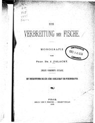
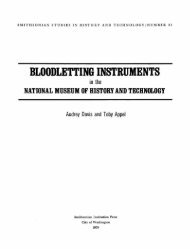
FIGURE 1.—Minimum-reading<br />
<strong>the</strong>rmometer <strong>and</strong> barometer<br />
flown by Gustave Hermite<br />
in 1892. (From W. de<br />
Fonvielle, Les Ballons-<br />
Sondes, Paris, 1899.)<br />
417^420). <strong>The</strong> maximum height, 10.8 kilometers, that was attained<br />
by an open-gondola, manned, free-balloon in 1901, also<br />
was too low to discern <strong>the</strong> tropopause; it was limited by <strong>the</strong><br />
SMITHSONIAN STUDIES IN HISTORY AND TECHNOLOGY<br />
maximum altitude at which humans can survive by breathing<br />
bottled oxygen. (<strong>The</strong> pressurized, closed-gondola balloon that<br />
made possible manned ascents to higher altitudes did not appear<br />
until 1931.) By 1894, some balloonsondes were returning<br />
data from altitudes <strong>of</strong> 18 kilometers. Thus, <strong>the</strong> balloonsonde<br />
constituted <strong>the</strong> only means <strong>of</strong> probing <strong>the</strong> upper reaches <strong>of</strong> <strong>the</strong><br />
atmosphere during <strong>the</strong> late nineteenth <strong>and</strong> early twentieth centuries.<br />
<strong>The</strong> first payloads flown by Hermite involved a crude instrument<br />
(Figure 1) that provided only minimum temperature <strong>and</strong><br />
pressure readings. By 1893, he was using a "baro<strong>the</strong>rmograph,"<br />
which was capable <strong>of</strong> providing a continuous<br />
strip-chart record <strong>of</strong> pressure <strong>and</strong> temperature for <strong>the</strong> entire<br />
flight (made with special nonfreezing ink for balloon use). His<br />
payload was an adaptation <strong>of</strong> a laboratory device (Figure 2)<br />
made by <strong>the</strong> well-known instrument firm <strong>of</strong> Richard Bro<strong>the</strong>rs<br />
<strong>of</strong> Paris, in which a Bourdon tube <strong>the</strong>rmometer <strong>and</strong> an aneroid<br />
barometer were coupled to a clockwork-driven pen-<strong>and</strong>-ink recorder.<br />
This instrument was used in a flight to almost 16 kilometers<br />
(de Fonvielle, 1899).<br />
<strong>The</strong> weight <strong>of</strong> <strong>the</strong> baro<strong>the</strong>rmograph required <strong>the</strong> use <strong>of</strong> a<br />
large (113 cubic meter) <strong>and</strong> costly balloon, <strong>and</strong> by 1895 Hermite<br />
was using a new device (Figure 3), which was designed<br />
especially for use with balloons. <strong>The</strong> pen-<strong>and</strong>-ink recorder was<br />
replaced by tracing points on smoked paper, <strong>and</strong> a helical bimetallic<br />
<strong>the</strong>rmometer was used ra<strong>the</strong>r than a Bourdon tube.<br />
<strong>The</strong>se innovations, toge<strong>the</strong>r with generally lighter construction,<br />
reduced weight, cost, <strong>and</strong> complexity <strong>and</strong> increased reliability<br />
(de Fonvielle, 1899).<br />
In 1894, <strong>the</strong> year after Hermite's first balloon flight, an American<br />
meteorologist, William Eddy, obtained data using a similar<br />
Richard instrument attached to a kite. This flight, which was <strong>the</strong><br />
first time a complex meteorograph had been lifted by kite,<br />
reached a height <strong>of</strong> 470 meters (Eddy, 1898:452). After this success,<br />
meteorological instruments were designed especially for<br />
use with kites <strong>and</strong>, later, with captive balloons. A notable example<br />
is <strong>the</strong> Richard baro<strong>the</strong>rmohygrograph <strong>of</strong> 1896. This design,<br />
originally suggested by Abbot Lawrence Rotch, founder <strong>and</strong> director<br />
<strong>of</strong> Blue Hill Observatory near Boston, Massachusetts,<br />
was a prototype for most <strong>of</strong> <strong>the</strong> later payload designs used for<br />
kites, captive balloons, <strong>and</strong> balloonsondes (Tiss<strong>and</strong>ier, 1896).<br />
<strong>The</strong> original instrument (Figure 4) was capable <strong>of</strong> measuring<br />
relative humidity, using a hair hygrometer, as well as pressure<br />
<strong>and</strong> temperature. 1 This device marked <strong>the</strong> advent <strong>of</strong> <strong>the</strong><br />
three-sensor system (<strong>the</strong>rmometer, barometer, hygrometer) that<br />
remains <strong>the</strong> basis for meteorological probes today.<br />
Kites <strong>and</strong> captive balloons could not reach <strong>the</strong> altitudes<br />
achieved by balloonsondes, but <strong>the</strong>y could repeatedly carry<br />
al<strong>of</strong>t heavy instruments without incurring much additional cost<br />
because <strong>the</strong> fixed expenses <strong>of</strong> <strong>the</strong> overall system, including<br />
motor-driven winches <strong>and</strong> cabling, were an appreciable portion<br />
<strong>of</strong> <strong>the</strong> cost per flight. This was not true <strong>of</strong> <strong>the</strong> balloonsonde,<br />
which was a complete system in itself. Hence, payload weight
NUMBER 53<br />
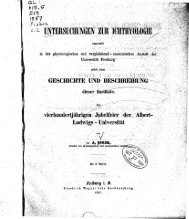
FIGURE 2 (above).—Baro<strong>the</strong>rmograph made by <strong>the</strong> firm <strong>of</strong> Richard Bro<strong>the</strong>rs <strong>of</strong><br />
Paris, 1893. <strong>The</strong> device used a Bourdon <strong>the</strong>rmometer <strong>and</strong> two aneroid chambers<br />
coupled to pen-arms that traced a record on a clockwork-driven cylinder.<br />
(From de Fonvielle, Les Ballons-Sondes, Paris, 1899.)<br />
FIGURE 3 (right).—An improved baro<strong>the</strong>rmograph used by Gustave Hermite in<br />
1895. <strong>The</strong> unit used a stylus to scratch a record on a smoked paper in place <strong>of</strong><br />
<strong>the</strong> pen-<strong>and</strong>-ink recordings used earlier. (From de Fonvielle, Les Ballons-Sondes,<br />
Paris, 1899.)
SMITHSONIAN STUDIES IN HISTORY AND TECHNOLOGY<br />
UitiiiiiiltiUizt^r.ir.u<br />
II II . II M.I ..-:rs::nsi£:«u:uu:<br />
»»«»•• jlgf<br />
• I • I i iliiinj • «••«••••*« •*<br />
i m • HI • ii, i -• *«»*«•*>*••••><br />
• < > I- I! ! i !OT »•'••' «•••••<br />
I II 1*11 I J«»l »••••• • ^»<br />
i i • 14 ' ' I •"• •• I HUH •*•#•**<br />
I .< !< i i •»»»•• • i •»;?^ x^<br />
l> 4 * •!••••• • • • * r»* #•«•« i *
NUMBER 53<br />
FIGURE 4B.—Photo <strong>of</strong> <strong>the</strong> original version made by Richard Bro<strong>the</strong>rs for use with captive balloons. (Instrument<br />
in NMAH collection, catalog number MHT 308209; <strong>Smithsonian</strong> photo 48467-H.)<br />
loons used in <strong>the</strong> 1890s were essentially identical to <strong>the</strong> first<br />
unmanned balloon launched by Jacques Charles in 1783. 2 Such<br />
balloons were <strong>the</strong> "fixed-volume" type, that is, <strong>the</strong> envelope<br />
was made <strong>of</strong> a nonstretch material that was fully inflated on <strong>the</strong><br />
ground. <strong>The</strong> neck or "appendix" <strong>of</strong> <strong>the</strong> balloon was left open to<br />
allow gas to escape during <strong>the</strong> ascent, which prevented <strong>the</strong> exp<strong>and</strong>ing<br />
balloon from bursting in <strong>the</strong> rarified air at high alti<br />
tude. <strong>The</strong>se balloons decreased <strong>the</strong>ir speed <strong>of</strong> ascent with increasing<br />
altitude, <strong>and</strong>, because <strong>the</strong>ir descent depended upon <strong>the</strong><br />
gradual loss <strong>of</strong> gas, <strong>the</strong>y had a prolonged "float." Both <strong>of</strong> <strong>the</strong>se<br />
characteristics were undesirable. <strong>The</strong> fact that <strong>the</strong> speed <strong>of</strong> ascent<br />
was not constant meant that <strong>the</strong> ventilation <strong>of</strong> sensors was<br />
variable, which made it difficult to interpret <strong>the</strong> data <strong>the</strong>y provided.<br />
Also, <strong>the</strong> prolonged float meant that <strong>the</strong> balloons <strong>of</strong>ten
SMITHSONIAN STUDIES IN HISTORY AND TECHNOLOGY<br />
FIGURE 5.—Balloonsonde built by <strong>the</strong> firm <strong>of</strong> Bosch in 1896 for German meteorologist Hugo Hergesell. This<br />
represents a balloonsonde version <strong>of</strong> <strong>the</strong> Richard Bro<strong>the</strong>rs instrument shown in Figure 4B. (From H. Hergesell,<br />
Meteorologischen Zeitschrift, volume 14, 1897.)<br />
travelled great distances from <strong>the</strong> launch point before l<strong>and</strong>ing,<br />
making recovery costly <strong>and</strong> time consuming.<br />
In 1901, German meteorologist Richard Assmann revolutionized<br />
unmanned balloon technology by introducing <strong>the</strong> use<br />
<strong>of</strong> sealed rubber balloons (Stringer, 1972:53). <strong>The</strong>se were made<br />
<strong>of</strong> specially processed rubber so <strong>the</strong> balloons could stretch to<br />
more than two <strong>and</strong> one-half times <strong>the</strong>ir launch diameter before<br />
bursting. <strong>The</strong>oretically, this allowed <strong>the</strong>m to reach altitudes exceeding<br />
20 kilometers (a height sometimes achieved in practice).<br />
Rubber balloons provided two significant advantages<br />
over <strong>the</strong> fixed-volume balloons: first, because <strong>the</strong>y exp<strong>and</strong>ed<br />
during ascent, <strong>the</strong>y tended to exhibit a fairly constant speed <strong>of</strong><br />
ascent, which made sensor data more reliable; <strong>and</strong> second, <strong>the</strong>y<br />
promptly burst at maximum altitude. <strong>The</strong> payload quickly de-
NUMBER 53<br />
FIGURE 6.—Solar-homing balloonsonde built<br />
<strong>and</strong> flown by French scientist A. de la Baume-<br />
Pluvinel in 1899. <strong>The</strong> purpose <strong>of</strong> this sophisticated<br />
device was to measure part <strong>of</strong> <strong>the</strong> solar<br />
spectrum at high altitudes where radiation<br />
traverses only a small portion <strong>of</strong> <strong>the</strong> earth's<br />
atmosphere. (From A. de la Baume-Pluvinel,<br />
L'Aerophile, volume 2, 1903.)<br />
scended on a parachute, which considerably reduced recovery<br />
times. Moreover, such balloons <strong>of</strong>fered two means <strong>of</strong> payload<br />
recovery: descent by a single parachute, which was used with<br />
low-cost payloads when timely recovery was important, <strong>and</strong><br />
<strong>the</strong> multiple-balloon technique, which was used with costly,<br />
one-<strong>of</strong>-a-kind payloads when a s<strong>of</strong>t l<strong>and</strong>ing <strong>and</strong> a high probability<br />
<strong>of</strong> retrieval were essential. <strong>The</strong> first method became st<strong>and</strong>ard<br />
for meteorological balloonsondes, whereas <strong>the</strong> second<br />
was characteristic <strong>of</strong> research flights involving hard-to-replace<br />
special instrumentation (for example, with <strong>the</strong> first radiosonde).<br />
<strong>The</strong> multiple-balloon technique (which depended upon <strong>the</strong><br />
use <strong>of</strong> rubber balloons) was introduced by Hergesell in 1904.<br />
<strong>The</strong> single balloon <strong>and</strong> parachute combination was replaced by<br />
two or more smaller balloons <strong>of</strong> equivalent lifting power. Although<br />
<strong>the</strong> balloons were designed to burst at roughly <strong>the</strong> same<br />
altitude, it was certain that one balloon would burst before <strong>the</strong><br />
o<strong>the</strong>rs, allowing <strong>the</strong> remaining balloons <strong>and</strong> <strong>the</strong> payload to descend<br />
slowly to a s<strong>of</strong>t l<strong>and</strong>ing. This method enhanced <strong>the</strong> likelihood<br />
<strong>of</strong> retrieval because <strong>the</strong> remaining balloon(s) floated<br />
above <strong>the</strong> grounded payload, acting as a signal to potential<br />
finders (Hergesell, 1904:200).<br />
Although rubber balloons were not reusable (as were balloons<br />
made <strong>of</strong> silk or goldbeater's skin), <strong>the</strong>y were less costly;<br />
hence, <strong>the</strong> average cost per flight was not appreciably higher.<br />
Moreover, <strong>the</strong> new balloon technology promised even greater<br />
cost reduction if payloads could be lightened <strong>and</strong> rubber balloons<br />
made smaller. This in turn suggested <strong>the</strong> possibility <strong>of</strong><br />
sending up large numbers <strong>of</strong> balloonsondes, making <strong>the</strong> possibility<br />
<strong>of</strong> routinely obtaining synoptic data on <strong>the</strong> upper atmosphere<br />
a meteorological reality.<br />
William Dines was <strong>the</strong> first to solve <strong>the</strong> payload weight<br />
problem (Dines, 1906:101) by eliminating <strong>the</strong> costly clockwork-driven<br />
recorder <strong>and</strong> <strong>the</strong> complicated mechanical linkages<br />
between sensor arm <strong>and</strong> recording arm <strong>and</strong> substituting a small,<br />
highly polished, flat, metal surface on which <strong>the</strong> arm <strong>of</strong> <strong>the</strong><br />
sensor scratched a line (Figure 7). <strong>The</strong> total deflection was very<br />
small, necessitating <strong>the</strong> use <strong>of</strong> a microscope to read <strong>the</strong> recording,<br />
but this was a small price to pay for <strong>the</strong> considerable decrease<br />
in cost <strong>and</strong> weight <strong>and</strong> <strong>the</strong> increase in reliability. Similar<br />
designs, emphasizing simplicity <strong>and</strong> light weight, were produced<br />
in Europe <strong>and</strong> were used in balloonsonde flights before<br />
World War I (Middleton, 1969a: 100).<br />
None<strong>the</strong>less, most <strong>of</strong> <strong>the</strong> upper-atmosphere data used in<br />
wea<strong>the</strong>r forecasting still were obtained from instruments flown<br />
on kites <strong>and</strong> captive balloons because <strong>the</strong> recorded data could<br />
be recovered quickly by simply reeling in <strong>the</strong> te<strong>the</strong>red vehicle,<br />
whereas balloonsonde records were only recovered after a considerable<br />
time. Thus, <strong>the</strong> balloonsonde was primarily a means<br />
<strong>of</strong> conducting geophysical research in <strong>the</strong> upper atmosphere.<br />
One <strong>of</strong> <strong>the</strong> more impressive examples <strong>of</strong> geophysical instrumentation<br />
was <strong>the</strong> balloonsonde (Figure 8) designed in 1913 by
10<br />
FIGURE 7.—Diagram <strong>of</strong> William<br />
Dines' balloon meteorograph.<br />
This device introduced<br />
<strong>the</strong> use <strong>of</strong> both a stylus<br />
to scratch minute displacement<br />
<strong>of</strong> sensors on polished<br />
metal surface <strong>and</strong> a microscope<br />
to read <strong>the</strong> resultant<br />
record. This approach dramatically<br />
lowered weight <strong>and</strong><br />
cost, making it feasible to<br />
launch balloonsondes in considerable<br />
numbers. (From W.<br />
Dines, Symon 's Meteorological<br />
Magazine, volume 41,<br />
1906.)<br />
Charles Abbot <strong>of</strong> <strong>the</strong> Astrophysical Observatory <strong>of</strong> <strong>the</strong> <strong>Smithsonian</strong><br />
Institution to measure solar radiation at high altitudes<br />
(Abbot et al., 1915:1-26). Abbot's work is noteworthy not only<br />
because <strong>of</strong> its scientific results but also because it demonstrated<br />
that <strong>the</strong> existing unmanned balloon technology was capable <strong>of</strong><br />
l<strong>of</strong>ting payloads to very high altitudes.<br />
In designing his balloonsonde, Abbot adopted <strong>the</strong> photographic<br />
technique pioneered by Baume-Pluvinel. In Abbot's<br />
device (Figure 8), a clockwork drive rotated a drum <strong>and</strong> also<br />
SMITHSONIAN STUDIES IN HISTORY AND TECHNOLOGY<br />
briefly opened <strong>the</strong> shutter <strong>of</strong> a slit-like aperture in <strong>the</strong> housing<br />
<strong>of</strong> <strong>the</strong> drum. Light, which passed through <strong>the</strong> aperture, impinged<br />
on photographic film on <strong>the</strong> inner surface <strong>of</strong> <strong>the</strong> drum.<br />
At <strong>the</strong> same time <strong>the</strong> aperture was partly covered by <strong>the</strong> mercury<br />
<strong>of</strong> a <strong>the</strong>rmometer that rose or fell, depending upon <strong>the</strong><br />
temperature <strong>of</strong> an attached disk pyrheliometer. Thus, <strong>the</strong> length<br />
<strong>of</strong> <strong>the</strong> aperture image recorded on <strong>the</strong> film measured <strong>the</strong> disk<br />
temperature, which was a function <strong>of</strong> <strong>the</strong> solar radiation. In order<br />
to obtain a simultaneous measurement <strong>of</strong> pressure, <strong>the</strong> image<br />
made by a barometer recording arm also was projected<br />
onto <strong>the</strong> film, a la Baume-Pluvinel.<br />
Abbot used <strong>the</strong> multiple-balloon recovery technique that had<br />
been introduced by Hergesell, which had become <strong>the</strong> preferred<br />
method for use with costly, specialized balloonsondes. Abbot intended<br />
to l<strong>of</strong>t his balloonsondes to <strong>the</strong> highest possible altitudes<br />
so as to maximize <strong>the</strong> reliability <strong>of</strong> extrapolating <strong>the</strong> measured<br />
value <strong>of</strong> solar radiation to <strong>the</strong> value that existed outside <strong>the</strong> blanket<br />
<strong>of</strong> air surrounding <strong>the</strong> earth. He used special rubber balloons<br />
that were designed <strong>and</strong> made by a company in Russia, which<br />
had produced balloons capable <strong>of</strong> reaching extremely high altitudes<br />
<strong>and</strong> which had produced most <strong>of</strong> <strong>the</strong> sounding balloons<br />
used in Europe prior to World War I (Abbott et al, 1915).<br />
Abbot constructed <strong>and</strong> flew five balloonsondes <strong>of</strong> this type,<br />
at Avalon, California, <strong>and</strong> Fort Omaha, Nebraska, in 1913—<br />
1914. One flight not only obtained useful data on solar radiation,<br />
but also set an altitude record for an unmanned balloon in<br />
<strong>the</strong> United States (32,643 meters) (Abbott et al., 1915). This altitude<br />
was extraordinary for that era. Balloons capable <strong>of</strong><br />
reaching this height generally were not available until after<br />
World War II. <strong>The</strong> Russian firm that made <strong>the</strong>se rubber balloons<br />
did not survive World War I; indeed, even its name is unknown.<br />
3 Thus, <strong>the</strong> secret <strong>of</strong> processing <strong>the</strong> rubber to increase<br />
its stretchability <strong>and</strong> its resistance to chemical attack by <strong>the</strong> relatively<br />
high concentration <strong>of</strong> ozone above 25 kilometers also<br />
was lost. (Present-day high-altitude balloons are made <strong>of</strong><br />
ozone-resistant plastic.)<br />
<strong>The</strong> disappearance <strong>of</strong> <strong>the</strong> Russian firm created a serious<br />
problem for researchers. For example, in 1919, when Robert<br />
Millikan, an American physicist <strong>and</strong> future Nobel Laureate,<br />
constructed a balloonsonde capable <strong>of</strong> measuring environmental,<br />
high-energy radiation (later called cosmic rays) above 25<br />
kilometers, he had great trouble finding suitable balloons (Millikan,<br />
1950:210). He did not obtain usable balloons from a<br />
United States manufacturer until 1921, but <strong>the</strong>se still were incapable<br />
<strong>of</strong> reaching <strong>the</strong> desired altitude. 3 Millikan later designed<br />
a payload that was capable <strong>of</strong> measuring <strong>the</strong> intensity <strong>of</strong><br />
ionizing radiation as a function <strong>of</strong> altitude to a height <strong>of</strong> 32 kilometers<br />
(Figure 9). Like <strong>the</strong> instruments <strong>of</strong> Baume-Pluvinel<br />
<strong>and</strong> Abbot, Millikan's balloonsondes used a photographic<br />
method <strong>of</strong> data storage to record simultaneously <strong>the</strong> output <strong>of</strong> a<br />
small, bifilar electrometer <strong>and</strong> <strong>the</strong> movement <strong>of</strong> <strong>the</strong> arm <strong>of</strong> a<br />
pressure sensor (Millikan <strong>and</strong> Bowen, 1926). <strong>The</strong>se balloonsondes<br />
were flown in 1922, <strong>and</strong>, although <strong>the</strong> data were useful,<br />
<strong>the</strong> maximum altitude achieved (15.5 kilometers) was far lower
NUMBER 53 11<br />
m<br />
M.<br />
^^^^^figte<br />
:;.JlMWWMk..s..-<br />
1<br />
1 |<br />
.vij^^K;: 1 ><br />
; Tffi^MPffi****- : '"- j '• '^^^^^^^ ^<br />
jp4 ^^B<br />
&sSaBBK&r£idtim- 1111111111 ':'v<br />
\ I<br />
,1| ^<br />
"~*-l M<br />
,4?<br />
11<br />
|S|<br />
.<br />
12 SMITHSONIAN STUDIES IN HISTORY AND TECHNOLOGY<br />
FIGURE 10.—S.P. Fergusson's balloon meteorograph designed in 1919. This represents <strong>the</strong> final development, in<br />
terms <strong>of</strong> low weight <strong>and</strong> cost, <strong>of</strong> <strong>the</strong> Richard Bro<strong>the</strong>rs design concept exemplified by <strong>the</strong> instrument shown in<br />
Figure 4B. In <strong>the</strong> 1920s, this approach, which still utilized a clockwork-driven recorder, was increasingly superseded<br />
by balloonsondes based upon Dines' instrument shown in Figure 7. (Instrument in NMAH collection, catalog<br />
number MHT 319822; <strong>Smithsonian</strong> photo 61837-A.)<br />
FIGURE 11.—Balloon meteorograph<br />
designed by Lawrence Dines, 1929.<br />
This represents <strong>the</strong> final development<br />
<strong>of</strong> design approach first introduced<br />
by William Dines in <strong>the</strong> early<br />
1900s. (From W. Middleton <strong>and</strong> A.<br />
Spilhaus, Meteorological Instruments,<br />
1953, fig. 166.)<br />
than Millikan had hoped for—a result <strong>of</strong> <strong>the</strong> failure <strong>of</strong> rubber<br />
manufacturers to achieve <strong>the</strong> quality <strong>of</strong> <strong>the</strong> pre-war Russian<br />
balloons.<br />
Rubber manufacturers in Europe <strong>and</strong> <strong>the</strong> United States did<br />
provide balloons that were quite satisfactory for <strong>the</strong> more modest<br />
altitude ranges required by most meteorological researchers.<br />
Moreover, <strong>the</strong> use <strong>of</strong> such meteorological balloonsondes<br />
increased after World War I because using kites <strong>and</strong> captive<br />
balloons for obtaining routine meteorological data had become<br />
more difficult after about 1910, as a result <strong>of</strong> <strong>the</strong> proliferation<br />
<strong>of</strong> electric power lines in Europe <strong>and</strong> in <strong>the</strong> United States. Accidents<br />
resulting from <strong>the</strong> contact <strong>of</strong> <strong>the</strong> wire cables <strong>of</strong> captive<br />
balloons <strong>and</strong> kites with electric power lines demonstrated <strong>the</strong><br />
dangers inherent in <strong>the</strong> use <strong>of</strong> te<strong>the</strong>red vehicles. Thus, although<br />
captive balloons were used throughout World War I, <strong>the</strong>ir use<br />
was limited to less populated regions after <strong>the</strong> war.<br />
<strong>The</strong> availability <strong>of</strong> airplanes as instrument platforms compensated<br />
somewhat for <strong>the</strong> decline in <strong>the</strong> use <strong>of</strong> kites <strong>and</strong> captive<br />
balloons, as did <strong>the</strong> more frequent use <strong>of</strong> balloonsondes to<br />
obtain routine meteorological data. Thus, in <strong>the</strong> 1920s <strong>the</strong> increased<br />
use <strong>of</strong> balloonsondes prompted renewed efforts to design<br />
lighter <strong>and</strong> cheaper payloads (Middleton, 1969b:98).<br />
After World War I, a number <strong>of</strong> balloonsondes, with <strong>and</strong><br />
without clockwork-driven recorders, were produced that emphasized<br />
simplicity <strong>and</strong> low weight. An instrument (Figure 10)<br />
designed by American scientist S.P. Fergusson exemplified <strong>the</strong><br />
American balloonsonde <strong>of</strong> that era (Middleton, 1969a:99). Its<br />
clockwork-driven recorder, however, proved to be too complicated.<br />
More successful designs were based upon <strong>the</strong> concept <strong>of</strong><br />
Dines, which used <strong>the</strong> small displacements <strong>of</strong> <strong>the</strong> sensors <strong>the</strong>mselves<br />
to scribe a record <strong>of</strong> temperature <strong>and</strong> pressure. This ver-
NUMBER 53 13<br />
FIGURE 12.—Jaumotte meteorograph <strong>of</strong> 1931. This is an example <strong>of</strong> a European instrument that was strongly<br />
influenced by <strong>the</strong> Dines design. (Instrument in NMAH collection, catalog number MHT 319823; <strong>Smithsonian</strong><br />
photo 48467-E.)<br />
sion strongly influenced <strong>the</strong> design <strong>of</strong> meteorological balloonsondes<br />
from <strong>the</strong> early 1900s through <strong>the</strong> 1930s (Middleton <strong>and</strong><br />
Spilhaus, 1953:231).<br />
In <strong>the</strong> late 1920s, Dines' original design was modified by his<br />
son Lawrence (who, like his distinguished fa<strong>the</strong>r, became a<br />
well-known meteorologist) to include a hygrometer. <strong>The</strong> instrument<br />
(Figure 11) measured temperature, pressure, <strong>and</strong> humidity.<br />
<strong>The</strong> device was mounted inside a light bamboo frame that<br />
provided great shock absorption <strong>and</strong> was so rugged that <strong>the</strong><br />
parachute was eliminated. <strong>The</strong> entire unit, including frame,<br />
weighed only 100 grams <strong>and</strong> was capable <strong>of</strong> being l<strong>of</strong>ted by a<br />
small (350 gram) rubber balloon (Middleton <strong>and</strong> Spilhaus,<br />
1953). This probably represented <strong>the</strong> most sophisticated design<br />
<strong>of</strong> a lightweight, low-cost, nontelemetering balloonsonde for<br />
obtaining synoptic meteorological data. Dines' 1929 meteorograph<br />
had features that influenced <strong>the</strong> subsequent designs <strong>of</strong><br />
most European balloonsonde meteorographs (Middleton,<br />
1969a: 100). For example, a unit designed by French meteorologist<br />
Jean Jaumotte (Figure 12) is an example <strong>of</strong> a related design.<br />
In summary, by 1929, <strong>the</strong> technology <strong>of</strong> unmanned sounding<br />
balloons had developed to a point that made <strong>the</strong> balloonsonde<br />
<strong>the</strong> most effective tool for studying <strong>the</strong> upper reaches <strong>of</strong> <strong>the</strong> atmosphere.<br />
Until <strong>the</strong> advent <strong>of</strong> <strong>the</strong> World War II rocket, <strong>the</strong>re<br />
was no o<strong>the</strong>r vehicle capable <strong>of</strong> reaching 30-kilometer heights.<br />
Moreover, <strong>the</strong> Baume-Pluvinel, Abbot, <strong>and</strong> Millikan balloonsondes<br />
conclusively showed that important geophysical information<br />
could be obtained, using complex payloads <strong>of</strong> sophisticated<br />
design. On <strong>the</strong> o<strong>the</strong>r h<strong>and</strong>, <strong>the</strong> success <strong>of</strong> <strong>the</strong> Dines-type<br />
instrument, coupled with small rubber balloons, demonstrated<br />
that <strong>the</strong> balloonsonde also was <strong>of</strong> meteorological value for <strong>the</strong><br />
collection <strong>of</strong> synoptic wea<strong>the</strong>r data at lower altitudes.
14 SMITHSONIAN STUDIES IN HISTORY AND TECHNOLOGY<br />
<strong>The</strong> major problem <strong>of</strong> <strong>the</strong> balloonsonde, in both high-altitude<br />
geophysical research <strong>and</strong> in <strong>the</strong> collection <strong>of</strong> meteorological<br />
data at low altitudes, was payload recovery. <strong>The</strong> probability <strong>of</strong><br />
recovery was low in some unpopulated locations (such as <strong>the</strong><br />
Arctic), <strong>and</strong> <strong>the</strong> loss <strong>of</strong> <strong>the</strong> data from one-<strong>of</strong>-a-kind payloads in<br />
special research flights was very costly. For relatively inexpensive<br />
meteorological balloonsondes that were launched in quantity,<br />
<strong>the</strong> loss <strong>of</strong> <strong>the</strong> data from an occasional lost payload was not<br />
serious, but <strong>the</strong> considerable lapse <strong>of</strong> time between <strong>the</strong> flight<br />
<strong>and</strong> recovery <strong>of</strong> <strong>the</strong> data significantly reduced <strong>the</strong> usefulness <strong>of</strong><br />
balloonsondes in wea<strong>the</strong>r forecasting.<br />
In <strong>the</strong> late 1920s, <strong>the</strong> advent <strong>of</strong> <strong>the</strong> radiosonde was a "natu<br />
ral" development <strong>of</strong> <strong>the</strong> balloonsonde whose evolution was determined<br />
mostly by advances in radio technology; that is, <strong>the</strong><br />
necessary <strong>the</strong>oretical groundwork for <strong>the</strong> radiosonde existed<br />
long before such an instrument was produced. However, <strong>the</strong><br />
possibility <strong>of</strong> linking balloon-borne sensors to a ground station<br />
via radio depended upon <strong>the</strong> development <strong>of</strong> transmitter components<br />
<strong>of</strong> suitable size, weight, power, <strong>and</strong> ability to survive<br />
<strong>the</strong> temperatures <strong>and</strong> pressures to which balloon payloads were<br />
subjected. Indeed, <strong>the</strong> first radiosondes utilized principles <strong>of</strong><br />
telemetering by wire that had been understood more than three<br />
quarters <strong>of</strong> a century earlier, <strong>and</strong> <strong>the</strong>y embodied principles <strong>of</strong><br />
radio that had been well understood for almost two decades.
<strong>The</strong> development <strong>of</strong> <strong>the</strong> electromagnetic telegraph progressed<br />
rapidly after about 1830, <strong>and</strong> by 1840 many miles <strong>of</strong><br />
circuits had been built. At that time it was apparent to scientists<br />
that <strong>the</strong>re were at least two ways in which <strong>the</strong> telegraph could<br />
be applied to problems <strong>of</strong> meteorological data ga<strong>the</strong>ring. First,<br />
data already recorded could be transmitted very quickly to centers<br />
for analysis <strong>and</strong> archival storage. Second, <strong>and</strong> more intriguing,<br />
<strong>the</strong> instruments <strong>the</strong>mselves could be connected by<br />
telegraph wire to deliver <strong>the</strong>ir data directly to <strong>the</strong> place where it<br />
would be used. Both applications came into use fairly quickly,<br />
but <strong>the</strong> second approach presented difficulties (Borden <strong>and</strong><br />
Thynell, 1948).<br />
Prior to 1840, information transmitted by telegraph had to<br />
originate in a discretely coded or symbolic form. In normal<br />
(nonmeteorological) message transmission, this form was st<strong>and</strong>ard<br />
language, including numerals <strong>and</strong> punctuation marks. Different<br />
schemes <strong>of</strong> representing alphabets <strong>and</strong> numerals were<br />
available, such as <strong>the</strong> Morse-Vail code, but <strong>the</strong>se were only<br />
translations <strong>of</strong> <strong>the</strong> original symbols. <strong>The</strong>y were, never<strong>the</strong>less,<br />
still discrete symbols <strong>and</strong> were easily sent over <strong>the</strong> telegraph as<br />
such.<br />
Meteorological data presented a fundamentally different requirement.<br />
Data from <strong>the</strong> <strong>the</strong>rmometer, barometer, <strong>and</strong> windregistering<br />
devices were not discrete but, ra<strong>the</strong>r, were continuous<br />
or analog in form. Scratching this data on a smoked drum<br />
or inking it on paper was simple as long as <strong>the</strong> drum or paper<br />
was in direct contact with <strong>the</strong> sensing device itself. Indeed,<br />
<strong>the</strong>se, or closely allied methods, were <strong>the</strong> universal recording<br />
system for all early meteorographs. Transmitting such analog<br />
data to a remote location, without an observer to first "read"<br />
<strong>the</strong> data <strong>and</strong> convert it to discrete symbols, was a very difficult<br />
problem.<br />
This problem first became apparent with <strong>the</strong> attempt to send<br />
graphic or pictoral images over <strong>the</strong> telegraph. Although <strong>the</strong>se<br />
images were not considered "data," <strong>the</strong> problem was <strong>the</strong> same.<br />
Part <strong>of</strong> <strong>the</strong> solution was already at h<strong>and</strong>. A marking scheme for<br />
symbols had been developed in 1828 that used an electrochemical<br />
indicator connected to an electrostatic telegraph. <strong>The</strong> missing<br />
link, a way to produce simultaneous <strong>and</strong> continuous marking<br />
at both ends <strong>of</strong> a transmission path, was worked out <strong>and</strong><br />
patented in 1842 by an English physicist, Alex<strong>and</strong>er Bain.<br />
Bain's patent incorporated <strong>the</strong> electrochemical marking system<br />
<strong>and</strong> brilliantly adapted a time-synchronization scheme developed<br />
by French scientist Claude Chappe in order to preserve<br />
<strong>the</strong> geometric integrity <strong>of</strong> <strong>the</strong> graphical data (Garratt, 1965).<br />
<strong>The</strong> system used pendulums at both ends <strong>of</strong> <strong>the</strong> transmission<br />
2. Preradio Telemetering, 1842-1894<br />
15<br />
path as shown in Bain's 1842 patent (Figure 13) (Ranger,<br />
1926:2).<br />
A pendulum at <strong>the</strong> receiver (shown at right in Figure 13) had<br />
a slightly longer natural period than a similar pendulum at <strong>the</strong><br />
sending station (shown at <strong>the</strong> left). <strong>The</strong> sending pendulum<br />
closed a circuit at one extreme <strong>of</strong> its swing <strong>and</strong> energized an<br />
electromagnet through <strong>the</strong> telegraph lines to capture <strong>the</strong> receiving<br />
pendulum near <strong>the</strong> end <strong>of</strong> its swing. <strong>The</strong> receiving pendulum<br />
could not swing past its starting position before <strong>the</strong> electromagnet<br />
captured it. If it did, synchronization with <strong>the</strong><br />
sending pendulum, which was intended to release both simultaneously<br />
from <strong>the</strong>ir starting positions, would be lost. When <strong>the</strong><br />
sending pendulum reversed direction to start ano<strong>the</strong>r swing, its<br />
contact opened <strong>and</strong> <strong>the</strong> receiving pendulum began in perfect<br />
synchronization. <strong>The</strong> slight difference in natural period had no<br />
effect on <strong>the</strong> average period <strong>of</strong> <strong>the</strong> receiving pendulum because<br />
synchronization was reestablished every cycle.<br />
Bain's facsimile was probably <strong>the</strong> earliest version <strong>of</strong> analog<br />
data-transmission techniques. It clearly provided a prototype<br />
for telemeteorographs capable <strong>of</strong> directly sending analog data<br />
<strong>and</strong> lacked only radio to be <strong>the</strong> prototype <strong>of</strong> an analog radiosonde.<br />
After 1837, Charles Wheatstone in Engl<strong>and</strong> concentrated on<br />
improving <strong>the</strong> electromagnetic mechanisms used in <strong>the</strong> telegraph<br />
system. His ideas subsequently influenced <strong>the</strong> development<br />
<strong>of</strong> meteorological instruments (Garratt, 1965). Particularly<br />
impressive was a system derived from Chappe's time<br />
coding, which removed most <strong>of</strong> <strong>the</strong> burden from <strong>the</strong> operator<br />
for accurate interpretation <strong>of</strong> <strong>the</strong> telegraph symbols. It consisted<br />
<strong>of</strong> a continuously stepping disc at <strong>the</strong> sending station<br />
synchronized with a similar disc at <strong>the</strong> receiver. <strong>The</strong> disc was<br />
made to pause at <strong>the</strong> position <strong>of</strong> symbols to be recorded. <strong>The</strong><br />
improvement over Chappe's device was that <strong>the</strong>se discs were<br />
synchronized over <strong>the</strong> two-wire circuit.<br />
In 1843, Wheatstone introduced <strong>the</strong> first "telemeteorograph,"<br />
a device that transmitted overl<strong>and</strong> by wire <strong>the</strong> readings<br />
<strong>of</strong> a barometer <strong>and</strong> a <strong>the</strong>rmometer to a receiving station<br />
many miles from <strong>the</strong> sensors (Middleton, 1969a:317). Moreover,<br />
<strong>the</strong> possibility <strong>of</strong> transmitting such meteorological data<br />
from kites or balloons also was investigated. In <strong>the</strong> same year,<br />
Wheatstone devised a telemetering <strong>the</strong>rmometer for use with a<br />
captive balloon. <strong>The</strong> electrical output <strong>of</strong> <strong>the</strong> <strong>the</strong>rmometer was<br />
connected to <strong>the</strong> ground by <strong>the</strong> balloon's te<strong>the</strong>r, which incorporated<br />
two copper wires that transmitted <strong>the</strong> signals to a<br />
l<strong>and</strong>-based receiver. Interestingly, this concept was ab<strong>and</strong>oned<br />
<strong>and</strong> was not tried again until 1917. <strong>The</strong> "immediacy" <strong>of</strong> <strong>the</strong><br />
data obtained in this way probably was perceived as a negligi-
16 SMITHSONIAN STUDIES IN HISTORY AND TECHNOLOGY<br />
-s'rs<br />
FIGURE 13.—Alex<strong>and</strong>er Bain's two-pendulum concept. This is a reproduction <strong>of</strong> <strong>the</strong> diagram in Bain's 1842<br />
patent. (From R. Ranger, Proceedings <strong>of</strong> <strong>the</strong> Institute <strong>of</strong> Radio Engineers, volume 14, 1926.)<br />
ble improvement because te<strong>the</strong>red kites <strong>and</strong> balloons carrying<br />
self-recording instruments could be cranked down within minutes<br />
<strong>of</strong> reaching <strong>the</strong>ir maximum altitude, thus allowing <strong>the</strong><br />
timely retrieval <strong>of</strong> data. <strong>The</strong> use <strong>of</strong> overl<strong>and</strong> telegraphy links to<br />
sensors in remote locations also was developed in <strong>the</strong> midnineteenth<br />
century.<br />
About 1868, a Dutch pr<strong>of</strong>essor, F. van Rysselberghe, developed<br />
a meteorograph, using <strong>the</strong> earlier ideas <strong>of</strong> Wheatstone <strong>and</strong><br />
o<strong>the</strong>rs. It converted readings <strong>of</strong> pressure, temperature, <strong>and</strong><br />
wind speed to markings on a rotating drum. In 1874, ano<strong>the</strong>r<br />
Dutch scientist, E.H. von Baumhauer, published a design suitable<br />
for telemeteorography from a balloon or kite, similar to<br />
van Rysselberghe's, which also produced markings on a<br />
smoothly rotating drum (Middleton, 1969a:318-321). Transmission<br />
<strong>of</strong> markings between similar drums required near synchronization<br />
<strong>of</strong> rotation, <strong>and</strong> von Baumhauer proposed <strong>the</strong> use<br />
<strong>of</strong> a signal over telegraph wire to start <strong>the</strong>m simultaneously.<br />
Subsequent synchronization relied upon constant speed <strong>of</strong> <strong>the</strong><br />
individual drums; an "open-loop" method identical in principle<br />
to <strong>the</strong> electrostatic telegraph system that Chappe had devised<br />
almost a hundred years earlier.<br />
A deficiency <strong>of</strong> von Baumhauer's telemeteorograph was that<br />
<strong>the</strong> rotation speed <strong>of</strong> one clock- or motor-driven drum could<br />
not be made perfectly equal to ano<strong>the</strong>r, given <strong>the</strong> technology <strong>of</strong><br />
that time. Thus <strong>the</strong> receiving drum would eventually drift out<br />
<strong>of</strong> step with <strong>the</strong> transmitter. Working to improve performance<br />
<strong>of</strong> <strong>the</strong> telemeteorograph, H. OU<strong>and</strong>, a Dutch instrument maker,<br />
built an elaborate system in 1877, using a sensor design similar<br />
to von Baumhauer's drum <strong>and</strong> incorporating a pendulum synchronization<br />
system identical in principle to Bain's (Middleton,<br />
1969a:324). Periodic synchronization <strong>of</strong> <strong>the</strong> rotating drums<br />
greatly shortened <strong>the</strong> period during which <strong>the</strong>y were required<br />
to maintain constant speed <strong>and</strong> thus allowed satisfactory operation<br />
for an indefinite period. Oll<strong>and</strong> personally knew von<br />
Baumhauer <strong>and</strong>, at his suggestion, used some <strong>of</strong> his ideas. It is<br />
unclear, however, if Oll<strong>and</strong> was familiar with Bain's work, so<br />
he may have "reinvented" Bain's two-pendulum concept. <strong>The</strong><br />
overall scheme became known as <strong>the</strong> "Oll<strong>and</strong> Cycle" (Middleton,<br />
1969a:324) as used in later instruments, including radiosondes,<br />
but it clearly incorporated ideas <strong>of</strong> Bain, von Baumhauer,<br />
<strong>and</strong> van Rysselberghe.<br />
This principle is extremely effective <strong>and</strong> inherently simple. It<br />
is so attractive that it has been used, in appropriate technology,
NUMBER 53<br />
$=*<br />
/"SN<br />
V*/<br />
/J^\<br />
(- J<br />
/Z?\<br />
f ~^^m$<br />
VB-V'<br />
-*• J"<br />
/^"•Af<br />
-' V<br />
FIGURE 14.—"Digital" transmission telemeteorograph designed by Luigi Cerebotani <strong>and</strong> Albert Silbermann.<br />
(From German Patent Number 93032, 1896.)<br />
17
li SMITHSONIAN STUDIES IN HISTORY AND TECHNOLOGY<br />
by virtually every development in data communications up to<br />
<strong>the</strong> present. 4 <strong>The</strong> concept, reduced to its most basic form, involves<br />
<strong>the</strong> entrainment <strong>of</strong> one oscillator by ano<strong>the</strong>r, where <strong>the</strong><br />
degree <strong>of</strong> stability <strong>of</strong> <strong>the</strong> chosen oscillators is sufficient for <strong>the</strong><br />
purpose at h<strong>and</strong>. In communications, unsynchronized timekeeping<br />
devices with stable, short-term periods are used at<br />
sending <strong>and</strong> receiving ends <strong>of</strong> a path. <strong>The</strong> sending timekeeper<br />
resets <strong>the</strong> receiving timekeeper periodically by some means to<br />
a specific phase point to achieve long-term synchronization.<br />
A modern example is <strong>the</strong> mechanical teletype developed for<br />
text transmission, which evolved into a universal system <strong>of</strong><br />
asynchronous data transmission between computers. In <strong>the</strong>se<br />
systems, a signal is transmitted instructing <strong>the</strong> receiver to begin<br />
recognizing a prearranged number <strong>of</strong> elements (bits) <strong>of</strong> a fixedlength<br />
message at a predetermined rate. After <strong>the</strong> prearranged<br />
number <strong>of</strong> elements, <strong>the</strong> receiver waits for a signal indicating<br />
that <strong>the</strong> sending interval is over, <strong>the</strong>n waits for a new start signal<br />
<strong>and</strong> <strong>the</strong> cycle repeats.<br />
<strong>The</strong> only o<strong>the</strong>r synchronization scheme in common use for<br />
data telemetry is one in which timing information is contained<br />
within <strong>the</strong> overall symbol stream. Timing information modulates<br />
<strong>the</strong> transmitted signal orthogonally to <strong>the</strong> data so that both<br />
can be separated at <strong>the</strong> receiver. This technique originated after<br />
1940 <strong>and</strong> did not come into use with meteorological data until<br />
<strong>the</strong> beginning <strong>of</strong> rocket telemetry. It has never seen significant<br />
use in mass-produced balloon-borne radiosondes.<br />
A significant deficiency <strong>of</strong> <strong>the</strong> van Rysselberghe-Oll<strong>and</strong> systems,<br />
as well as any derivative <strong>of</strong> <strong>the</strong> Bain facsimile, was that<br />
<strong>the</strong>y dem<strong>and</strong>ed clockwork motions <strong>of</strong> virtually uniform speeds<br />
during <strong>the</strong> period <strong>of</strong> each observation. In attempting to alleviate<br />
this problem, an ingenious system was invented <strong>and</strong> patented in<br />
1896 by two Swiss scientists, Luigi Cerebotini <strong>and</strong> Albert Silbermann.<br />
This system established a fundamentally new method<br />
<strong>of</strong> information transmission that converts <strong>the</strong> magnitude <strong>of</strong> a<br />
continuous scalar variable into a digital value <strong>and</strong> <strong>the</strong>n transmits<br />
<strong>the</strong> value, using discrete symbols. <strong>The</strong> accuracy with<br />
which <strong>the</strong> original value can be transmitted is not at all limited<br />
by <strong>the</strong> method <strong>of</strong> transmission, given sufficient time. <strong>The</strong> accuracy<br />
<strong>of</strong> analog data, on <strong>the</strong> o<strong>the</strong>r h<strong>and</strong>, is closely linked to <strong>the</strong><br />
parameters <strong>of</strong> <strong>the</strong> transmission system. Analog-to-digital conversion<br />
<strong>of</strong> data before transmission is virtually universal in<br />
modern telemetry for <strong>the</strong> purpose <strong>of</strong> maintaining high accuracy.<br />
In <strong>the</strong>ir device (Figure 14), Cerebotini <strong>and</strong> Silbermann incorporated<br />
a number <strong>of</strong> electrical conducting bars inset in a drum<br />
<strong>of</strong> insulating material. As <strong>the</strong> drum rotated, <strong>the</strong> arm <strong>of</strong> a meteorological<br />
sensor rested against it. <strong>The</strong> number <strong>of</strong> bars contacted<br />
per revolution depended upon <strong>the</strong> position <strong>of</strong> <strong>the</strong> arm, hence it<br />
was necessary only to count <strong>the</strong> "on-<strong>of</strong>f' contacts at <strong>the</strong> o<strong>the</strong>r<br />
end <strong>of</strong> <strong>the</strong> telegraph line to obtain <strong>the</strong> reading <strong>of</strong> <strong>the</strong> meteorological<br />
sensor activating <strong>the</strong> arm. <strong>The</strong> transmission was "digital,"<br />
<strong>and</strong> accuracy was thus independent <strong>of</strong> <strong>the</strong> uniformity <strong>of</strong><br />
<strong>the</strong> rotation speed <strong>of</strong> <strong>the</strong> drum (although it was limited by <strong>the</strong><br />
number <strong>of</strong> conducting bars incorporated in <strong>the</strong> drum). This<br />
method was subsequently adopted by French scientist, Robert<br />
Bureau, in constructing his first radiosonde (see pages 31-33).<br />
As <strong>the</strong> technology <strong>of</strong> radiosondes developed, however, <strong>the</strong>re<br />
was a strong prejudice in favor <strong>of</strong> analog systems, which had<br />
been <strong>the</strong> basis <strong>of</strong> meteorographs for more than one hundred<br />
years. <strong>The</strong> usual method for data display was a two-dimensional<br />
graph, <strong>and</strong> it was difficult for instrument designers to<br />
break away from a mechanism that operated in <strong>the</strong> same way,<br />
even though <strong>the</strong> advantages <strong>of</strong> digital coding were obvious.<br />
Consequently, <strong>the</strong>re was a mixture <strong>of</strong> analog <strong>and</strong> digital representations<br />
<strong>of</strong> data as <strong>the</strong> radiosonde evolved.<br />
By <strong>the</strong> turn <strong>of</strong> <strong>the</strong> century, interest in overl<strong>and</strong> telemetering<br />
<strong>of</strong> meteorological data from remote stations had waned; however,<br />
<strong>the</strong> basic principles <strong>of</strong> telemetering, embodied in nineteenth-century<br />
telemeteorographs, were <strong>the</strong> source <strong>of</strong> ideas that<br />
scientists used to develop <strong>the</strong> radiosonde. <strong>The</strong>se ideas, coupled<br />
with <strong>the</strong> developments in radio, made <strong>the</strong> radiosonde possible.
By 1850, <strong>the</strong> telegraph had become firmly established as a<br />
means <strong>of</strong> transmission <strong>of</strong> language <strong>and</strong> data; however, <strong>the</strong>re already<br />
was frustration with <strong>the</strong> difficulty <strong>and</strong> expense <strong>of</strong> installing<br />
wires. It had been known since <strong>the</strong> work <strong>of</strong> Faraday <strong>and</strong><br />
Henry that electric currents could produce effects in a circuit<br />
not connected by wires to <strong>the</strong> source <strong>of</strong> <strong>the</strong> current. <strong>The</strong> phenomenon,<br />
called mutual induction, had fascinated experimenters<br />
in Europe <strong>and</strong> America as a possibility for creating a wireless<br />
version <strong>of</strong> <strong>the</strong> telegraph. <strong>The</strong> range <strong>of</strong> induction in <strong>the</strong><br />
1850s was disappointing, however, only a few meters. Although<br />
induction transmission was extended to a few kilometers<br />
by <strong>the</strong> 1890s, it still did not <strong>of</strong>fer a workable means <strong>of</strong><br />
wireless communication (Blake, 1928:282-284).<br />
Between 1865 <strong>and</strong> 1886, many experimenters demonstrated<br />
<strong>the</strong> existence <strong>of</strong> propagating electromagnetic radiation. A great<br />
deal <strong>of</strong> this work was unpublished or was reported in popular<br />
literature, ra<strong>the</strong>r than in scientific journals. A few articles described<br />
results that probably were caused by radiation, but <strong>the</strong><br />
phenomenon was poorly understood <strong>and</strong> was not well explained<br />
by <strong>the</strong> investigators (Thomson, 1853).<br />
<strong>The</strong> early confusion between induction <strong>and</strong> radiation is not<br />
difficult to underst<strong>and</strong>. Electromagnetic induction is related to<br />
radiation, as explained by a <strong>the</strong>ory advanced by James Clerk<br />
Maxwell (Maxwell, 1865). However, Maxwell's <strong>the</strong>ory remained<br />
beyond <strong>the</strong> ken <strong>of</strong> most investigators until Heinrich<br />
Hertz, who, working with a firm underst<strong>and</strong>ing <strong>of</strong> ma<strong>the</strong>matics<br />
<strong>and</strong> Maxwell's equations, first conducted energy from a spark<br />
discharge by wire to a metal loop containing a small gap that<br />
would spark after <strong>the</strong> discharge (Hertz, 1888). Hertz <strong>the</strong>n set up<br />
an identical loop at a distance <strong>and</strong> observed that it sparked at<br />
<strong>the</strong> same time. He subsequently proved <strong>the</strong> wave nature <strong>of</strong> this<br />
interaction by carefully demonstrating reflection, refraction, interference,<br />
<strong>and</strong> velocity. Hertz correctly showed that <strong>the</strong> wavelength<br />
was about 25 centimeters. Although his maximum range<br />
<strong>of</strong> transmission was only 19 meters, this was more than 50<br />
wavelengths. <strong>The</strong> range <strong>of</strong> transmission, expressed in wavelengths,<br />
was more important than just an extension <strong>of</strong> communication<br />
distance. It proved that <strong>the</strong> signals were indeed radiation<br />
<strong>and</strong> not caused by <strong>the</strong> induction effect. Maxwell's<br />
equations show that <strong>the</strong> electric field at a distance from a conducted<br />
current can have components proportional to wavelength<br />
divided by distance, distance squared, <strong>and</strong> distance<br />
cubed. Only <strong>the</strong> component inversely proportional to distance<br />
is associated with self-propagating radiation; <strong>the</strong> o<strong>the</strong>rs produce<br />
induction effects. By a distance <strong>of</strong> 50 wavelengths from<br />
<strong>the</strong> source, <strong>the</strong> inverse squared <strong>and</strong> cubed terms will have essentially<br />
disappeared, leaving only <strong>the</strong> true radiation.<br />
3. Radio Telemetry, 1895-1929<br />
19<br />
Maxwell's radiation became known in <strong>the</strong> literature as Hertzian<br />
Waves. Experimenters duplicated <strong>the</strong> work <strong>and</strong> extended<br />
<strong>the</strong> experiments across greater distances for application to<br />
wireless communication. <strong>The</strong> prospect <strong>of</strong> a lucrative business<br />
in making apparatus to replace wire telegraphy interested both<br />
skilled scientists <strong>and</strong> tinkerers (Blake, 1928). Individuals who<br />
used various techniques <strong>and</strong> who achieved successful results in<br />
<strong>the</strong> period 1887 to 1890 included Edouard Branly, Alex<strong>and</strong>er<br />
Popov, Gugliemo Marconi, Nicholas Tesla, Ferdin<strong>and</strong> Braun,<br />
<strong>and</strong> Sir Oliver Lodge. By 1895, Marconi had shown conclusively<br />
that a practical system <strong>of</strong> wireless signalling was possible.<br />
By 1896, Popov <strong>and</strong> Marconi had demonstrated wireless<br />
systems with a range <strong>of</strong> about 10 kilometers. <strong>The</strong> next year<br />
Marconi, who sought commercial success, had reached a range<br />
<strong>of</strong> 70 kilometers. (In 1909, Marconi <strong>and</strong> Braun, whose "sparkless<br />
antenna system" represented a significant improvement,<br />
shared a Nobel prize for <strong>the</strong> development <strong>of</strong> wireless telegraphy.)<br />
At <strong>the</strong> turn <strong>of</strong> <strong>the</strong> century, wire telegraphy spanned thous<strong>and</strong>s<br />
<strong>of</strong> miles in Europe <strong>and</strong> America. Wireless <strong>of</strong>fered <strong>the</strong> possibility<br />
<strong>of</strong> communication across long distances without <strong>the</strong> costly<br />
networks <strong>of</strong> wire. This was a compelling goal, <strong>and</strong> enormous<br />
amounts <strong>of</strong> money <strong>and</strong> effort were dedicated to its accomplishment.<br />
<strong>The</strong>re was a rapid progression to large, powerful apparatus<br />
that seemed to be <strong>the</strong> means <strong>of</strong> obtaining greater range. Use<br />
<strong>of</strong> such huge equipment to return meteorological data from<br />
al<strong>of</strong>t appeared not only impractical but foolish, so <strong>the</strong> transition<br />
from balloonsondes to radiosondes was not seriously considered<br />
at that time.<br />
<strong>The</strong> brute-force style <strong>of</strong> transmission apparatus was confirmed<br />
by contemporary quantitative <strong>the</strong>ory. Large antennas<br />
created higher-amplitude radiation fields <strong>and</strong> consequently<br />
larger signals at <strong>the</strong> receiver. <strong>The</strong> wavelength at which <strong>the</strong>se<br />
large antennas absorbed energy (from impulse or spark excitation)<br />
<strong>and</strong> radiated efficiently was proportional to <strong>the</strong>ir dimensions.<br />
5 Consequently, long wavelengths were necessary for<br />
communications, on <strong>the</strong> order <strong>of</strong> <strong>the</strong> antenna dimensions. Empirical<br />
studies undertaken by Hertz (1888) showed that range<br />
was proportional to power <strong>and</strong> antenna size, as predicted by<br />
Maxwell's <strong>the</strong>ory. Absorption <strong>of</strong> <strong>the</strong> waves increased with distance<br />
<strong>and</strong> appeared to become virtually complete below about<br />
200 meters, an added obstacle to shorter wavelengths <strong>and</strong><br />
smaller, lighter equipment.<br />
In <strong>the</strong> years after Hertz's work, a major obstacle to greater<br />
range, in addition to power <strong>and</strong> propagation, was <strong>the</strong> sensitivity<br />
<strong>of</strong> <strong>the</strong> receiving apparatus. At <strong>the</strong> outset it was obvious that a<br />
receiver that depended upon <strong>the</strong> display <strong>of</strong> sparks was imprac-
20 SMITHSONIAN STUDIES IN HISTORY AND TECHNOLOGY<br />
tical for use at distances needed for communication. A solution<br />
was at h<strong>and</strong>, however, even before Hertz's work, in a scheme<br />
used by Hughes for induction receiving in <strong>the</strong> 1870s (Hughes,<br />
1878). He had utilized a receiving circuit that passed current<br />
through an assembly <strong>of</strong> carbon powder originally developed as<br />
a sound-to-current transducer for <strong>the</strong> emerging technology <strong>of</strong><br />
sound transmission over telegraph wires. Various experimenters<br />
(see Howeth, 1963:15-23) had demonstrated properties <strong>of</strong><br />
this type <strong>of</strong> device, consisting <strong>of</strong> an evacuated tube <strong>of</strong> metal filings<br />
between silver electrodes that would serve as a sensitive<br />
detector for wireless radiation. Called <strong>the</strong> "coherer," it was perfected<br />
by two American engineers, Forbes <strong>and</strong> Lodge, between<br />
1892 <strong>and</strong> 1894 (Lodge, 1908:32-56). This device quickly became<br />
<strong>the</strong> st<strong>and</strong>ard wireless detector, with virtually no competition<br />
until <strong>the</strong> invention <strong>of</strong> Fessenden's electrolytic detector in<br />
1903.<br />
Fundamental improvements were made in wireless technology<br />
that extended transmission range (but did nothing to reduce<br />
<strong>the</strong> size <strong>of</strong> <strong>the</strong> required equipment) between 1897 <strong>and</strong><br />
1900. In order to improve conversion <strong>of</strong> power into radiation,<br />
Lodge used inductance <strong>and</strong> capacitance to make <strong>the</strong> antenna<br />
circuit resonant at <strong>the</strong> wavelength desired for transmission. In<br />
addition to improving efficiency by better matching <strong>of</strong> impedance<br />
between <strong>the</strong> antenna <strong>and</strong> generator, this substantially narrowed<br />
<strong>the</strong> range <strong>of</strong> wavelengths in <strong>the</strong> radiation. When Marconi<br />
applied similar tuning to <strong>the</strong> antenna circuit <strong>of</strong> a receiver,<br />
<strong>the</strong> overall effect was dramatic. He achieved <strong>the</strong> first transatlantic<br />
contact on 12 December 1901, at about 1000 meters<br />
wavelength. Fur<strong>the</strong>r progress in narrowing <strong>the</strong> b<strong>and</strong>width <strong>of</strong><br />
transmissions followed shortly, with development <strong>of</strong> <strong>the</strong><br />
Poulsen arc <strong>and</strong> <strong>the</strong> Fessenden-Alex<strong>and</strong>erson alternators. Instead<br />
<strong>of</strong> <strong>the</strong> relatively inefficient process <strong>of</strong> generating a wide<br />
b<strong>and</strong> <strong>of</strong> wavelengths by spark discharge <strong>and</strong> selecting only part<br />
<strong>of</strong> this spectrum by a resonant circuit, <strong>the</strong>se devices generated<br />
oscillations more-or-less in <strong>the</strong> wavelength range desired. An<br />
additional reason for improved efficiency was that radio-frequency<br />
energy generated by spark transmitters was discontinuous,<br />
whereas alternators generated continuous undamped<br />
waves. <strong>The</strong> time-averaged power available for transmitting was<br />
<strong>the</strong>refore greater. Reactive parameters <strong>of</strong> <strong>the</strong> antenna circuit<br />
still influenced efficiency <strong>of</strong> energy conversion to radiation,<br />
but wavelength was fairly well defined <strong>and</strong> could be selected<br />
for favorable propagation (Morecr<strong>of</strong>t, 1921:511-513).<br />
In 1904, <strong>the</strong> first developments occurred that would lead to<br />
<strong>the</strong> construction <strong>of</strong> small radio transmitters that operated at<br />
wavelengths suitable for meteorological data transmission<br />
from balloon-borne instruments. <strong>The</strong> beginning, however, lies<br />
not with transmission but with reception. J.A. Fleming, who<br />
earlier had worked with Marconi to establish transatlantic wireless,<br />
used <strong>the</strong> "Edison effect" to achieve high sensitivity as a<br />
detector, replacing Branly's coherer. <strong>The</strong> Edison effect, which<br />
Edison had reported in 1883, refers to <strong>the</strong> phenomenon <strong>of</strong> electric<br />
current flow through an evacuated tube containing electrodes.<br />
By 1901, physicists understood this effect, <strong>and</strong> Fleming<br />
used it to "rectify" or convert <strong>the</strong> radio frequencies picked up<br />
by a receiver to direct current in a headphone or galvanometer<br />
(Chaffee, 1933:1-16).<br />
Fleming's achievement quickly led o<strong>the</strong>r investigators to use<br />
<strong>the</strong>se "vacuum tubes." In 1906, Lee de Forest showed that by<br />
adding a third electrode, current flow between <strong>the</strong> o<strong>the</strong>r two<br />
electrodes could be controlled, using virtually no power (de<br />
Forest, 1906). Still, probably as a result <strong>of</strong> Fleming's lead,<br />
early work on application <strong>of</strong> <strong>the</strong>se tubes was concentrated on<br />
improving <strong>the</strong> sensitivity <strong>of</strong> radio reception. Unintentionally,<br />
this approach was fortunate for eventual application to meteorological<br />
data trans-mission because it fostered development <strong>of</strong><br />
small, low-powered circuits before <strong>the</strong> obsession with high-energy<br />
transmission could dominate <strong>the</strong> entire effort <strong>of</strong> engineers.<br />
In fact, much <strong>of</strong> <strong>the</strong> early work with tubes, called "audions,"<br />
was devoted to amplification <strong>of</strong> telephone communications<br />
over wire; also a comparatively low-power application (de Forest,<br />
1906).<br />
From 1905 to 1915, progress in radio technology was steady<br />
but not spectacular. After 1915, <strong>the</strong> dem<strong>and</strong>s <strong>of</strong> <strong>the</strong> military<br />
services fighting in World War I gave impetus to <strong>the</strong> development<br />
<strong>of</strong> more efficient tubes <strong>and</strong> circuits. For example, in 1916,<br />
<strong>the</strong> first use <strong>of</strong> aircraft radios had occurred (Figure 15), although<br />
<strong>the</strong> radios still were too large to be adapted for balloonsonde<br />
use (Tyne, 1977:117). <strong>The</strong>re was intense competition for<br />
financial rights regarding inventions within <strong>the</strong> emerging business<br />
<strong>of</strong> radio, <strong>and</strong> patent litigation was common. Not until <strong>the</strong><br />
latter part <strong>of</strong> that period did developments in applied technology<br />
reach a point that promised help for scientists attempting to<br />
send data directly from a balloon carrying meteorological instruments.<br />
<strong>The</strong>re was no lack <strong>of</strong> interest in this application. German science<br />
historian Paul Beelitz (1954:67) reported a private communication<br />
from E.F. Herath, written in 1950, indicating that<br />
Herath <strong>and</strong> o<strong>the</strong>r German meteorologists, Max Robitzsch <strong>and</strong><br />
Alfred Wegner, considered using balloon-borne radio transmitters<br />
in <strong>the</strong> summer <strong>of</strong> 1914. <strong>The</strong> vacuum tubes that were available,<br />
however, such as <strong>the</strong> de Forest audions, were poorly evacuated,<br />
which rendered <strong>the</strong>m unpredictable in circuits. (Two<br />
American engineers, Langmuir <strong>and</strong> Arnold, succeeded in<br />
building much-improved high-vacuum tubes in 1912-1913 at<br />
<strong>the</strong> General Electric <strong>and</strong> AT&T laboratories, but <strong>the</strong>y did not<br />
reach production for several years (Tyne, 1977:133-157)). This<br />
defect, toge<strong>the</strong>r with fragile construction, made vacuum tubes<br />
unsuitable for service in <strong>the</strong> relatively hostile environment to<br />
which balloons ascend. Ano<strong>the</strong>r difficulty was that, in 1914,<br />
<strong>the</strong> only circuit design that could make a balloon-borne transmitter<br />
practical, <strong>the</strong> continuous wave oscillator, was still in its<br />
infancy <strong>and</strong> was not widely known.<br />
This situation did not deter experimentation with radio-frequency<br />
energy to get data from balloons al<strong>of</strong>t. Pierre Idrac in<br />
France, <strong>and</strong> Herath <strong>and</strong> Robitzsch in Germany, in separate experiments<br />
during 1917, used radio-circuit techniques to send<br />
data down <strong>the</strong> wire <strong>of</strong> a te<strong>the</strong>red kite. No doubt some slight ra-
NUMBER 53 21<br />
1916<br />
FIGURE 15.—Gugliemo Marconi's air-to-ground radio, circa 1916. (From a Marconi Instrument Company advertising<br />
brochure mailed to <strong>the</strong> electronics industry in <strong>the</strong> spring <strong>of</strong> 1987.)<br />
diation did occur in <strong>the</strong> process, but no attempt to measure this<br />
was recorded (Middleton, 1969a:276).<br />
Early in 1917, Herath <strong>and</strong> Robitzsch produced a device in<br />
which a contact on a revolving drum touched a stylus <strong>of</strong> <strong>the</strong><br />
sensor <strong>and</strong> energized <strong>the</strong> primary <strong>of</strong> a small spark coil (Middleton,<br />
1969a: 103). <strong>The</strong> secondary <strong>of</strong> this coil was paralleled with<br />
a capacitor <strong>and</strong> spark gap. One side <strong>of</strong> this broadly tuned circuit<br />
was connected to <strong>the</strong> steel te<strong>the</strong>r <strong>of</strong> <strong>the</strong> kite. Detection was<br />
achieved by a telephone receiver connected to <strong>the</strong> kite. Data<br />
coding was analog by time interval. <strong>The</strong> stylus-drum contact<br />
was closed once each revolution <strong>of</strong> <strong>the</strong> drum at a fixed point on<br />
<strong>the</strong> drum, regardless <strong>of</strong> stylus position. It was closed again at a<br />
time dependent on <strong>the</strong> position <strong>of</strong> <strong>the</strong> stylus, <strong>the</strong>reby converting<br />
stylus position into a time interval. As long as <strong>the</strong> signal from<br />
both closings was clearly received, <strong>the</strong> scheme was self-calibrating<br />
<strong>and</strong> precise to about one degree centigrade for temperature<br />
readings.<br />
A more elaborate experiment was conducted in September <strong>of</strong><br />
1917, in France (Rome, 1936:278). Pierre Idrac used a self-interrupting<br />
spark gap, or "buzzer," in <strong>the</strong> balloon to excite a parallel-tuned<br />
circuit (Figure 16). <strong>The</strong> buzzer was energized by a<br />
contact driven from <strong>the</strong> meteorological sensor. <strong>The</strong> balloon<br />
te<strong>the</strong>r again served as an electrical conductor for <strong>the</strong> radio-frequency<br />
signals. Idrac significantly improved reception by using<br />
a parallel-tuned circuit coupled inductively to <strong>the</strong> te<strong>the</strong>r at <strong>the</strong><br />
ground. A rectifier <strong>and</strong> telephone receiver across this tuned circuit<br />
completed <strong>the</strong> receiving circuit. Idrac pointed out an important<br />
feature <strong>of</strong> this scheme that derived from <strong>the</strong> radio-frequency<br />
circuits: by using multiple transmitters tuned to<br />
different frequencies, <strong>the</strong> same te<strong>the</strong>r could conduct data simultaneously<br />
from several sensors without interference. On <strong>the</strong><br />
ground a tuned receiver could separate <strong>the</strong>se signals. Idrac also<br />
had a capacitor sensitive to temperature. This would code <strong>the</strong><br />
data into a frequency that could be measured on <strong>the</strong> ground.<br />
This technique subsequently was used by some radiosonde developers.<br />
<strong>The</strong> research <strong>of</strong> Herath, Robitzsch, <strong>and</strong> Idrac anticipated developments<br />
in radio technology that would lead to <strong>the</strong> balloon-borne<br />
radio transmission <strong>of</strong> meteorological data. <strong>The</strong>y already<br />
were working with <strong>the</strong> same radio-frequency energy <strong>and</strong><br />
circuit techniques that drove wireless telegraphy. It was only<br />
<strong>the</strong> lack <strong>of</strong> small, rugged, radio-frequency oscillators that kept<br />
<strong>the</strong>m from making this innovative transition.<br />
*
22 SMITHSONIAN STUDIES IN HISTORY AND TECHNOLOGY<br />
FIGURE 16.—Tuned circuit <strong>of</strong> Pierre Idrac, circa 1917, used in <strong>the</strong> meteorograph that transmitted sensor data via<br />
wire to a ground receiver. (From E. Ro<strong>the</strong>, Comptes Rendus, volume 170, 1920.)<br />
Although <strong>the</strong> vacuum tubes available in 1915 were <strong>of</strong> poor<br />
quality, a very wide range <strong>of</strong> applications had been forseen by<br />
companies interested in manufacturing tubes, <strong>and</strong> vigorous<br />
commercial development was begun. It was <strong>the</strong> three-element<br />
audion that made possible invention <strong>of</strong> <strong>the</strong> continuous-wave<br />
oscillator. This occurred during <strong>the</strong> search for more sensitive<br />
methods for wireless reception. Sometime after 1911, an audion<br />
circuit was built with substantial coupling or "feedback"<br />
from <strong>the</strong> resonant coil in <strong>the</strong> plate output to a similarly resonant<br />
coil in <strong>the</strong> input grid circuit. When <strong>the</strong> grid coil also was coupled<br />
to an antenna <strong>and</strong> <strong>the</strong> feedback was adjusted carefully, it<br />
proved to be an extremely sensitive detector <strong>of</strong> wireless transmissions.<br />
Adjustment for even more feedback caused <strong>the</strong> circuit<br />
to become unstable <strong>and</strong> to produce oscillations.<br />
<strong>The</strong> circuit, called a regenerative detector, was first described<br />
to <strong>the</strong> Institute <strong>of</strong> Radio Engineers by American engineer Edwin<br />
Armstrong in 1913 (Armstrong, 1917). Priority was controversial,<br />
however, <strong>and</strong> <strong>the</strong> courts later credited de Forest with<br />
originating <strong>the</strong> concept. Equally as important as its receiving<br />
virtues was <strong>the</strong> circuit's property <strong>of</strong> self-oscillation. <strong>The</strong> usefulness<br />
<strong>of</strong> this property probably was first recognized by Meissner,<br />
who received a German patent for an oscillator circuit in<br />
1913. However, <strong>the</strong> priority <strong>of</strong> this circuit also was disputed between<br />
Langmuir, Meissner, Armstrong, <strong>and</strong> de Forest, who<br />
again turned to <strong>the</strong> courts for resolution. In spite <strong>of</strong> <strong>the</strong>se arguments,<br />
a means finally was available for producing sustained,<br />
high-frequency, oscillating currents for radio transmission<br />
without <strong>the</strong> great size <strong>and</strong> inefficiency <strong>of</strong> <strong>the</strong> Poulsen arc or <strong>the</strong><br />
Alex<strong>and</strong>erson alternator. <strong>The</strong> circuit <strong>and</strong> vacuum tube did require<br />
optimization for producing high-frequency output as a<br />
transmitter, but <strong>the</strong>se developments soon took place. In 1913,<br />
Meissner demonstrated <strong>the</strong> use <strong>of</strong> a vacuum-tube oscillator for<br />
radiotelephony between Berlin <strong>and</strong> Nauen (Meissner, 1922).<br />
<strong>The</strong> gas-filled tube used in this experiment produced 10 watts<br />
<strong>of</strong> radio frequency (RF) output. By 1912, Langmuir <strong>and</strong> Arnold<br />
already had produced <strong>the</strong> high-vacuum tubes necessary for stable<br />
operation over a wide range <strong>of</strong> power, <strong>and</strong> <strong>the</strong> continuouswave<br />
(CW) oscillator began to dominate all o<strong>the</strong>r methods <strong>of</strong><br />
radio-power generation. By 1915, vacuum-tube oscillators<br />
were being used by AT&T <strong>and</strong> Bell broadcasting; one Bell application<br />
used 500 tubes in parallel (Craft <strong>and</strong> Colpitts,<br />
1919:310).<br />
It is important to trace <strong>the</strong> evolution <strong>of</strong> <strong>the</strong> CW oscillator because,<br />
even in its most rudimentary form, it is quite suitable as<br />
a radiosonde transmitter (Goldsmith, 1918). Due to size <strong>and</strong><br />
weight limitations imposed by <strong>the</strong> balloon environment, radiosonde<br />
CW circuits changed very little from <strong>the</strong> earliest design<br />
to <strong>the</strong> mass-produced radiosondes <strong>of</strong> <strong>the</strong> 1940s <strong>and</strong> 1950s. This<br />
circuit, a plate-tuned triode oscillator with inductively coupled<br />
feedback to <strong>the</strong> grid, was used in <strong>the</strong> earliest regenerative receivers<br />
(Figure 17). Its adaptation to radiosonde service (Figure<br />
18) required only <strong>the</strong> attention <strong>of</strong> meteorological scientists <strong>and</strong><br />
sufficiently rugged high-vacuum tubes. A final consideration—<br />
storage batteries with adequate capacity to power <strong>the</strong> tube filaments<br />
<strong>and</strong> plate circuit at <strong>the</strong> low temperatures al<strong>of</strong>t—was important<br />
but not critical to <strong>the</strong> genesis <strong>of</strong> a true radiosonde. Batteries<br />
large enough to overcome low efficiency could be carried<br />
by using larger balloons.<br />
After 1900, <strong>the</strong> work done by radio engineers was augmented<br />
by amateurs or hobbyists in Europe <strong>and</strong> America (Ster-
NUMBER 53 23<br />
V<br />
FIGURE 17.—Circuit by H.J. Round for using a three-electrode valve for beat<br />
reception, circa 1913. (From J. Fleming, <strong>The</strong> <strong>The</strong>rmionic Valve <strong>and</strong> Its <strong>Development</strong><br />
in Radiography <strong>and</strong> Telegraphy, London, 1919, fig. 112.)<br />
ling, 1928). <strong>The</strong>se enthusiastic individuals with, for <strong>the</strong> most<br />
part, no commercial motives, were highly innovative <strong>and</strong> did<br />
not have <strong>the</strong> obsession with high power <strong>and</strong> long wavelength<br />
that characterized "pr<strong>of</strong>essional" radio development. It is essential<br />
to include amateur radio technology in <strong>the</strong> history <strong>of</strong> radiosonde<br />
evolution because it brought about <strong>the</strong> development<br />
<strong>and</strong> use <strong>of</strong> low-power transmitting oscillators. In 1917, President<br />
Wilson ordered all amateur wireless stations dismantled<br />
<strong>and</strong> all commercial stations turned over to <strong>the</strong> U.S. Navy. <strong>The</strong><br />
policy did not, however, halt <strong>the</strong> hobbyist's valuable contributions<br />
to radio science because many took up similar work in<br />
government laboratories. Ano<strong>the</strong>r large group <strong>of</strong> amateurs contributed<br />
to <strong>the</strong> war effort by serving as wireless operators.<br />
<strong>The</strong> development <strong>of</strong> vacuum tubes suitable for operation <strong>of</strong> a<br />
triode CW oscillator as a balloon-borne radiosonde occurred<br />
Cs<br />
•ir-r<br />
p<br />
A-<br />
W¥\^<br />
—-H • • *<br />
C£<br />
B+<br />
FIGURE 18.—Tuned plate oscillator circuit used in radiosondes, circa 1934. LI<br />
<strong>and</strong> L2 are coupled to provide feedback for oscillation. Note <strong>the</strong> similarity to<br />
<strong>the</strong> circuit shown in Figure 17. (From W. Wenstrom, Monthly Wea<strong>the</strong>r Review,<br />
volume 62, 1934.)<br />
between 1914 <strong>and</strong> 1918, although <strong>the</strong> secrecy surrounding such<br />
work in World War I obscured <strong>the</strong> record <strong>of</strong> developments in<br />
vacuum tubes <strong>and</strong> low-power transmitting oscillators from<br />
1917 through about 1919. <strong>Development</strong> <strong>of</strong> vacuum tubes was<br />
both retarded by wartime secrecy <strong>and</strong>, at least regionally, advanced<br />
by wartime need for improved field communications.<br />
Low-power, battery-operated transmitters, using new, smaller,<br />
vacuum tubes, were built for military signaling, <strong>and</strong> descriptions<br />
<strong>of</strong> <strong>the</strong>m appeared in post-war literature. For example,<br />
Meissner (1922:3) described a high-vacuum tube transmitter<br />
with 10- to 15-watt output, built by <strong>the</strong> Telefunken Company in<br />
1915, <strong>and</strong> indicated that it was "practically <strong>the</strong> same arrangement<br />
as <strong>the</strong> transmitter used experimentally by <strong>the</strong> Allies at <strong>the</strong><br />
end <strong>of</strong> 1917 on <strong>the</strong> West Front." A French "R" type high-vacuum<br />
tube was patented in 1916 <strong>and</strong> used in Allied receivers.<br />
<strong>The</strong> filament requirements were 3.7 volts at 500 milliamps, <strong>and</strong><br />
75 volts was adequate for <strong>the</strong> plate supply. <strong>The</strong>se figures were<br />
compatible with <strong>the</strong> battery power supply for a field CW transmitter.<br />
<strong>The</strong> United States began to develop two-way radiotelephone<br />
sets shortly after its entry into <strong>the</strong> war for use on submarine<br />
chasers <strong>and</strong> airplanes. <strong>The</strong>se sets used st<strong>and</strong>ardized highvacuum,<br />
oxide-coated, filament tubes <strong>and</strong> had a simple, fieldserviceable<br />
design (Tyne, 1977:190-278; Blake, 1928:244-<br />
245). Large-scale production <strong>of</strong> this apparatus was not<br />
achieved in time for significant field use in airplanes by <strong>the</strong><br />
U.S. Army.<br />
Wartime need for small, portable equipment led to interest in<br />
shorter wavelengths. <strong>The</strong> initial reason was that smaller antennas<br />
would be more practical <strong>and</strong> easier to conceal in <strong>the</strong> field.<br />
Smaller antennas, however, required shorter wavelengths to be<br />
most efficient. This was a fortuitous development for balloon-borne<br />
transmitters because <strong>the</strong> few hundred meter wavelength<br />
<strong>of</strong> common radiotelegraphy was impractical for a balloon<br />
antenna. Initial experiments with shorter wavelengths<br />
brought an unexpected result. It was discovered that range
24<br />
FIGURE 19 (right).—Catalog <strong>and</strong> instruction book for building an apparatus for<br />
continuous wave operation, circa 1921. (From Anon., <strong>The</strong> Radio Industry, New<br />
York, 1928, fig. 3.)<br />
FIGURE 20 (below).—Circuit for using a three-electrode <strong>The</strong>rmion as a generator<br />
<strong>of</strong> oscillations, circa 1919. Coils R <strong>and</strong> L in <strong>the</strong> grid <strong>and</strong> <strong>the</strong> plate circuits<br />
are closely coupled. This circuit, which has remained virtually unchanged, <strong>and</strong><br />
a Hartley circuit, where <strong>the</strong> grid is tapped <strong>of</strong>f <strong>the</strong> plate coil, later became st<strong>and</strong>ard<br />
radiosonde transmitters. (From J. Fleming, <strong>The</strong> <strong>The</strong>rmionic Valve <strong>and</strong> Its<br />
<strong>Development</strong> in Radiography <strong>and</strong> Telegraphy, London, 1919, fig. 137.)<br />
B 400V<br />
r-^W«|l|l| l|l|lf-<br />
-ooosMfJ<br />
SMITHSONIAN STUDIES IN HISTORY AND TECHNOLOGY<br />
RADIO APPARATUS<br />
Amateur <strong>and</strong> Experimental Use<br />
^h INSTRUCTIONS *&r<br />
CONTINUOUS IWMB OPERATION<br />
Radio foi* Corporation<br />
\\<br />
•0005Mfd<br />
WTiLWORTH B1 ffllHNG ~ MBW YORK ClVC<br />
r\<br />
•p<br />
F
NUMBER 53 25<br />
could be increased substantially during daylight hours, to about<br />
<strong>the</strong> same range as nighttime. In 1916, Marconi made transmissions<br />
across more than 1600 kilometers in Europe, on a wavelength<br />
<strong>of</strong> 32 meters. He characterized <strong>the</strong>se as "beam" transmissions<br />
because <strong>the</strong> radiation was directed in a single<br />
direction by placing reflecting structures near <strong>the</strong> antenna<br />
(Weagaut <strong>and</strong> Waterman, 1918). Even shorter wavelengths (in<br />
<strong>the</strong> few meter range), called "ultra-short," were produced by<br />
numerous experimenters (Wenstrom, 1932). <strong>The</strong> benefits <strong>of</strong><br />
<strong>the</strong>se short wavelengths were confirmed after <strong>the</strong> war by Franklin<br />
in Engl<strong>and</strong>, Conrad in <strong>the</strong> United States, <strong>and</strong> by many amateurs<br />
on both continents. Early radiosonde prototypes were<br />
greatly improved through <strong>the</strong> use <strong>of</strong> shorter wavelengths.<br />
In late 1918, references to CW oscillator <strong>and</strong> miniature vacuum-tube<br />
development again appeared in <strong>the</strong> literature. Availability<br />
was a problem, especially to amateurs, because <strong>the</strong> wartime<br />
control <strong>of</strong> wireless operation <strong>and</strong> production was not<br />
rescinded immediately after <strong>the</strong> armistice. Authors speculated<br />
about when amateurs would have access again to <strong>the</strong> new vacuum<br />
tubes <strong>and</strong> suggested that such tubes would be <strong>of</strong> considerable<br />
use in transmitters. Civilian rights to radio, amateur <strong>and</strong><br />
commercial, were restored by <strong>the</strong> Government in 1919. Soon<br />
<strong>the</strong>re were many developments in radio science, both basic <strong>and</strong><br />
applied (Espenscheid, 1922). <strong>The</strong>re is no question that suitable<br />
circuit designs, as well as components for construction <strong>of</strong> a viable<br />
balloon-borne radio transmitter that could be modulated by<br />
meteorological sensors, existed by 1920. RCA was producing<br />
thous<strong>and</strong>s <strong>of</strong> triode vacuum tubes <strong>of</strong> types UV200, UV201, <strong>and</strong><br />
UV202, with an improved, oxide-coated, tungsten filament that<br />
required one ampere at five volts. Also, <strong>the</strong> de Forest company<br />
was still producing audions, mostly for amateur use (Tyne,<br />
1977:300-340). (In 1922, <strong>the</strong> UV201 was replaced by <strong>the</strong> type<br />
UV201A, requiring only 250 milliamperes <strong>of</strong> filament current,<br />
which had been developed by Western Electric for <strong>the</strong> U.S.<br />
Navy in 1920. Sixty-milliampere varieties followed shortly<br />
(Tyne, 1977:300-340).) <strong>The</strong> cover <strong>of</strong> a 1921 RCA parts catalog<br />
<strong>and</strong> instructional manual featured apparatus for <strong>the</strong> construction<br />
<strong>of</strong> CW transmitting gear (Figure 19). Amateur designs for<br />
small, one-tube transmitters proliferated. An example from a<br />
1920 journal is a single type VT-1 tube in a Hartley-type oscillator<br />
operated from dry batteries that provided 50 volts platesupply<br />
potential. (Basic oscillator types are named usually for<br />
<strong>the</strong> method <strong>of</strong> coupling between plate <strong>and</strong> grid circuits; <strong>the</strong><br />
Hartley oscillator is inductively coupled.) Similar designs were<br />
used by amateur radio enthusiasts in Germany <strong>and</strong> France. This<br />
transmitter could be on-<strong>of</strong>f keyed for telegraph code or plate<br />
modulated for telephony. It produced a few watts output operating<br />
on 300 meters (Figure 20). It could be placed into a balloon<br />
<strong>and</strong> on-<strong>of</strong>f keyed by a sensor, such as Idrac's revolving<br />
drum, to make a radiosonde.<br />
We did not, however, find any published record <strong>of</strong> such a<br />
complete <strong>and</strong> advanced development <strong>of</strong> radio transmitters for<br />
balloon use until 1927. Why this was so is a curiosity. <strong>The</strong> pioneers<br />
<strong>of</strong> radiosonde development, Blair, Bureau, Duckert, <strong>and</strong><br />
Moltchan<strong>of</strong>f, wrote after 1927 that <strong>the</strong>y had begun work on <strong>the</strong><br />
development <strong>of</strong> radio transmitters for use with free balloons in<br />
<strong>the</strong> early 1920s, but <strong>the</strong> results <strong>of</strong> <strong>the</strong>ir research did not appear<br />
at that time in pr<strong>of</strong>essional journals (see Section II, "<strong>The</strong> Early<br />
Years"). It seems unlikely that <strong>the</strong> development <strong>of</strong> a successful<br />
radiosonde would have gone unmentioned because Soviet <strong>and</strong><br />
German scientists, especially, later emphasized <strong>the</strong> priority <strong>of</strong><br />
<strong>the</strong>ir work.<br />
A likely explanation for this silence lies in <strong>the</strong> fact that adaptation<br />
<strong>of</strong> radio technology to <strong>the</strong> balloon environment was not<br />
easy, <strong>and</strong> scientists were not highly skilled in such adaptation.<br />
Also, as in most technological developments, <strong>the</strong> successful radiosondes<br />
<strong>of</strong> <strong>the</strong> early 1930s were <strong>the</strong> product <strong>of</strong> evolution in<br />
design concepts. Thus, development progressed from feasibility<br />
experiments in <strong>the</strong> early 1920s through rudimentary prototypes<br />
to practical balloon-borne radio transmitters, with most<br />
<strong>of</strong> <strong>the</strong> defects removed by 1927 to 1928. Developers <strong>of</strong> <strong>the</strong><br />
early radiosonde were more interested in creating a new technology<br />
for obtaining upper-atmospheric measurements than in<br />
doing atmospheric research per se. <strong>The</strong> extent to which <strong>the</strong> radiosonde<br />
developers were able to utilize directly <strong>the</strong> relatively<br />
mature radio technology <strong>of</strong> <strong>the</strong> period from 1920 to 1929 is<br />
very difficult to determine. It is possible, however, to trace this<br />
evolution from <strong>the</strong> fragmentary evidence in <strong>the</strong> literature.
II. <strong>The</strong> <strong>Radiosonde</strong>: <strong>Development</strong> <strong>and</strong> Application<br />
As is usual after a major war, <strong>the</strong> former World War I combatants<br />
undertook research to resolve military problems that<br />
had been exposed by <strong>the</strong> harsh light <strong>of</strong> battle. As part <strong>of</strong> such<br />
research, <strong>the</strong> applications <strong>of</strong> radiotelemetry to meteorology<br />
were investigated in Europe <strong>and</strong> <strong>the</strong> United States. Research<br />
was prompted by <strong>the</strong> burgeoning military need for meteorological<br />
data stimulated, primarily, by <strong>the</strong> increased reliance upon<br />
airplanes as weapons. More specifically, <strong>the</strong> military needed an<br />
all-wea<strong>the</strong>r means <strong>of</strong> obtaining timely information about <strong>the</strong><br />
winds al<strong>of</strong>t <strong>and</strong> <strong>the</strong> atmospheric temperature, pressure, <strong>and</strong> humidity<br />
at various altitudes in order to prepare synoptic wea<strong>the</strong>r<br />
maps. <strong>The</strong> war had revealed that such data were indispensable<br />
to a fully operational air force, <strong>and</strong>, <strong>the</strong>refore, research on improved<br />
means for obtaining <strong>the</strong>se data was sponsored by <strong>the</strong><br />
governments <strong>of</strong> Germany, <strong>the</strong> Soviet Union, France, <strong>and</strong> <strong>the</strong><br />
United States.<br />
In Germany, research on balloon-borne radio transmitters<br />
was begun in 1921 at <strong>the</strong> Lindenberg Observatory under <strong>the</strong> supervision<br />
<strong>of</strong> its director, H. Hergesell. Later, Hergesell<br />
(1932:50) wrote that such experiments were begun "long before<br />
<strong>the</strong> researches <strong>of</strong> foreign, <strong>and</strong> especially Russian, scientists."<br />
This appears to be an overstatement, although such research<br />
in o<strong>the</strong>r countries probably began after 1921. In 1923,<br />
both <strong>the</strong> United States <strong>and</strong> <strong>the</strong> Soviet Union initiated similar investigations;<br />
in 1925, France followed suit.<br />
Between 1921 <strong>and</strong> 1928, <strong>the</strong>re was an adaptation <strong>of</strong> spark<br />
technology <strong>and</strong> <strong>the</strong>n <strong>of</strong> vacuum-tube technology for radio transmission<br />
from free balloons. <strong>The</strong>se investigations primarily were<br />
to prove <strong>the</strong> feasibility <strong>of</strong> making a transmitter work in <strong>the</strong> balloon<br />
environment. Some early investigators sought a means <strong>of</strong><br />
tracking balloons al<strong>of</strong>t, in order to chart wind vectors. This application<br />
did not require any modulation <strong>of</strong> a radio signal, simply<br />
<strong>the</strong> signal itself. Indeed, <strong>the</strong> use <strong>of</strong> a radio signal to track a<br />
balloon to obtain information about wind velocity <strong>and</strong> direction<br />
as a function <strong>of</strong> altitude probably was <strong>the</strong> first application investigated<br />
in Germany <strong>and</strong> <strong>the</strong> United States (Blair, 1937).<br />
It is not surprising that this application was one <strong>of</strong> <strong>the</strong> first<br />
investigated. World War I had demonstrated that information<br />
about <strong>the</strong> winds al<strong>of</strong>t was important not only for airplane navigation,<br />
but also for accurate artillery fire <strong>and</strong> chemical warfare.<br />
(<strong>The</strong> use <strong>of</strong> poison gas in World War I had made a deep impression<br />
on military doctrine.) Conventional methods <strong>of</strong> tracking a<br />
pilot balloon by using <strong>the</strong>odolites worked well in daylight,<br />
when visibility was good, but <strong>the</strong>y were difficult to use at night<br />
(although lanterns were carried by <strong>the</strong> balloon) or when poor<br />
4. <strong>The</strong> Early Years, 1921-1928<br />
26<br />
CHOKE,<br />
C I vflUfilr<br />
a RCCW<br />
FIGURE 21.—William Blair's first radio-tracking transmitter, circa 1923-1924.<br />
"Buzzer" contacts in plate circuit ingeniously allowed voltage step-up so that<br />
<strong>the</strong> filament battery could also supply <strong>the</strong> plate. <strong>The</strong> unit was designed to be<br />
flown using a t<strong>and</strong>em-balloon recovery method, described in section 2. (From<br />
W. Blair <strong>and</strong> H. Lewis, Proceedings <strong>of</strong> <strong>the</strong> Institute <strong>of</strong> Radio Engineers, volume<br />
19, 1931.)<br />
wea<strong>the</strong>r conditions hampered visual contact. During World<br />
War I, sonic methods to overcome <strong>the</strong>se difficulties had been<br />
tried, but <strong>the</strong>se were found wanting, chiefly because <strong>of</strong> <strong>the</strong>ir<br />
limited range (Blair <strong>and</strong> Lewis, 1931:1532). <strong>The</strong>refore, <strong>the</strong> use
NUMBER 53 27<br />
FIGURE 22.—First transmitter operated in <strong>the</strong> stratosphere. <strong>The</strong> quarter-wave antenna measured 10.5 meters in<br />
length. It was suspended by balloons, <strong>and</strong> a transmitter hung at its end. With batteries, <strong>the</strong> entire assembly<br />
weighed 2.7 kilograms. Power consumption was four watts, <strong>and</strong> radiated power probably did not exceed one<br />
watt. From left to right are <strong>the</strong> filament battery, <strong>the</strong> vertical-axis keying windmill, <strong>and</strong> <strong>the</strong> transmitter (including<br />
plate batteries, inductances, <strong>and</strong> tubes). <strong>The</strong> unit was constructed entirely from commercially available parts.<br />
(From R. Bureau, La Meteorologie, volume 7, 1931.)<br />
<strong>of</strong> balloon-borne radios as an all-wea<strong>the</strong>r, night <strong>and</strong> day means<br />
to determine wind vectors promised to fulfill an important military<br />
need.<br />
In Germany, E.F. Herath, a meteorologist, who in 1917 was<br />
<strong>the</strong> first to use spark transmitters to send data along <strong>the</strong> te<strong>the</strong>r<br />
<strong>of</strong> a captive balloon, began to experiment with wireless transmitters<br />
<strong>of</strong> similar design. In 1921, he placed a transmitter on a<br />
free balloon <strong>and</strong> attempted to track it from <strong>the</strong> ground. <strong>The</strong> radio<br />
signal was detected by <strong>the</strong> ground receiver, but accurate<br />
tracking was not achieved (Beelitz, 1954:67).<br />
Somewhat more successful experiments were conducted in<br />
1923-1924 by Colonel William Blair at <strong>the</strong> U.S. Signal Corps<br />
laboratory at McCook Field, Ohio. Blair utilized a buzzer<br />
transmitter like that used in 1917 by Idrac, although Idrac's device<br />
transmitted signals by wire from a captive balloon. Blair's<br />
radio transmitter weighed less than one pound <strong>and</strong> was carried<br />
al<strong>of</strong>t on t<strong>and</strong>em balloons (Figure 21). <strong>The</strong> balloons were<br />
tracked successfully by radio signals for about twenty minutes,<br />
ascending to a height <strong>of</strong> almost 4 kilometers.<br />
Blair also began investigating <strong>the</strong> possibility <strong>of</strong> using a balloon-borne<br />
radio transmitter as a means <strong>of</strong> obtaining <strong>the</strong> wind<br />
velocities <strong>and</strong> air temperatures as a function <strong>of</strong> altitude (Blair<br />
<strong>and</strong> Lewis, 1931:1534). He had noted that radio transmitter<br />
characteristics changed because <strong>of</strong> <strong>the</strong> effects <strong>of</strong> temperature<br />
<strong>and</strong> o<strong>the</strong>r meteorological conditions. <strong>The</strong>se changes <strong>the</strong>n produced<br />
frequency changes in <strong>the</strong> transmitter signal. Instead <strong>of</strong><br />
attempting to design transmitters that were free from <strong>the</strong>se effects,<br />
Blair recognized that <strong>the</strong> effects <strong>the</strong>mselves constituted a<br />
means <strong>of</strong> obtaining meteorological data. Blair (1937:2) later<br />
wrote "This is possible because...a proper selection <strong>of</strong> [transmitter]<br />
materials <strong>and</strong> design provides an independent response<br />
to <strong>the</strong> different meteorological conditions that is quantitatively<br />
measurable." In o<strong>the</strong>r words, <strong>the</strong> radio transmitter could be<br />
converted into a radiosonde by using <strong>the</strong> components <strong>of</strong> <strong>the</strong><br />
transmitter as a kind <strong>of</strong> distributed "sensor" that could be calibrated<br />
to measure a specific meteorological parameter. According<br />
to Blair <strong>and</strong> Lewis (1931:1534), Blair constructed such a<br />
balloon-borne radio transmitter for measuring atmospheric<br />
temperature <strong>and</strong> made <strong>the</strong> first upper-air observations by this<br />
means early in 1924.<br />
Blair's device constituted a radiosonde, although this terminology<br />
was not introduced until 1931. Blair did not continue<br />
this work on radiotelemetry because in 1924 he was made chief<br />
meteorologist for <strong>the</strong> Army's around-<strong>the</strong>-world flight. After
28<br />
SMITHSONIAN STUDIES IN HISTORY AND TECHNOLOGY<br />
FIGURE 23.—Radio-Tracking transmitter designed by William Blair in 1927, using a CW vacuum-tube oscillator.<br />
(From Blair <strong>and</strong> Lewis, Proceedings <strong>of</strong> <strong>the</strong> Institute <strong>of</strong> Radio Engineers, volume 19, 1931, fig. 21.) This design<br />
was ingenious because it derived filament <strong>and</strong> plate supply from single 4.5 volt battery supplying about 200 milliamperes.<br />
<strong>The</strong> power supply was a type <strong>of</strong> self-energized inverter, somewhat like a buzzer. <strong>The</strong> magnetic field <strong>of</strong><br />
a transformer pulled open contacts in series with <strong>the</strong> primary <strong>and</strong> battery, causing sustained vibration <strong>of</strong> contacts.<br />
<strong>The</strong> secondary <strong>of</strong> <strong>the</strong> transformer stepped up <strong>the</strong> primary voltage to supply about 200 volts to <strong>the</strong> tube plate. <strong>The</strong><br />
plate coil <strong>of</strong> <strong>the</strong> oscillator was in <strong>the</strong> center <strong>of</strong> <strong>the</strong> antenna, which formed a center-fed dipole <strong>of</strong> 25 meters overall<br />
length. <strong>The</strong> operating wavelength was about 125 meters. <strong>The</strong> transmitter weighed 500 grams <strong>and</strong> was given <strong>the</strong><br />
Signal Corps designation BC-164.<br />
Blair completed this mission, he was given administrative assignments<br />
that occupied him for several years, to <strong>the</strong> exclusion<br />
<strong>of</strong> his research interests. Thus, although Blair's initial results<br />
were promising, he did not publish <strong>the</strong>m at <strong>the</strong> time (although<br />
he described <strong>the</strong>m in a later publication <strong>and</strong> lecture) (Blair <strong>and</strong><br />
Lewis, 1931; Blair, 1937). Despite <strong>the</strong> fact that Blair's transmitters<br />
were primitive, he demonstrated <strong>the</strong> feasibility <strong>of</strong> two<br />
applications that were among <strong>the</strong> most important meteorological<br />
uses <strong>of</strong> radio in <strong>the</strong> ensuing decades. He also showed that<br />
accurate radio-tracking <strong>of</strong> a balloon could determine wind vectors,<br />
<strong>and</strong> that it was possible to measure atmospheric parameters,<br />
such as air temperature, with a balloon-borne transmitter<br />
that relayed this information to a ground receiver. With <strong>the</strong> end<br />
<strong>of</strong> Blair's work in 1924, no substantial progress in this field<br />
was made in <strong>the</strong> United States for <strong>the</strong> next three years.<br />
<strong>The</strong> next significant advance occurred in France. Pierre Idrac<br />
<strong>and</strong> Robert Bureau had begun work at France's National Meteorology<br />
Office that, in 1927, led to <strong>the</strong> first use <strong>of</strong> a CW oscillator<br />
transmission from a balloon. This was an evolutionary advance<br />
from discharge-excited radiation, which had been used<br />
by Herath <strong>and</strong> by Blair, to radiation produced by a vacuumtube<br />
CW oscillator. 6<br />
Idrac <strong>and</strong> Bureau (1927:691) constructed a vacuum-tube CW<br />
radio that had a transmission wavelength <strong>of</strong> 42 meters. <strong>The</strong> signal<br />
was on-<strong>of</strong>f keyed by an air-actuated windmill device. <strong>The</strong><br />
unit (Figure 22) used t<strong>and</strong>em balloons <strong>and</strong> was flown on March<br />
3 <strong>and</strong> 7 <strong>of</strong> 1927, reaching an altitude <strong>of</strong> almost 14 kilometers.<br />
<strong>The</strong> radio signal was received by numerous stations at distances<br />
up to 500 kilometers. According to Idrac <strong>and</strong> Bureau<br />
(1927:692), <strong>the</strong> purpose <strong>of</strong> <strong>the</strong> flight was to "study propagation<br />
<strong>of</strong> short waves as a function <strong>of</strong> <strong>the</strong> altitude at which <strong>the</strong>y are
NUMBER 53 29<br />
emitted." <strong>The</strong>y concluded that <strong>the</strong>ir experiments "probably<br />
constituted <strong>the</strong> first reception <strong>of</strong> radio waves emitted in <strong>the</strong><br />
stratosphere."<br />
About <strong>the</strong> time Idrac <strong>and</strong> Bureau published <strong>the</strong>ir results,<br />
Blair resumed his research on radio-tracking balloons at <strong>the</strong><br />
Signal Corps laboratory, Fort Monmouth, New Jersey. In 1927,<br />
he designed <strong>and</strong> constructed an oscillator for high efficiency,<br />
using a type-199 vacuum tube (Blair <strong>and</strong> Lewis, 1931). <strong>The</strong><br />
transmitter weighed 500 grams <strong>and</strong> was given <strong>the</strong> Signal Corps<br />
designation BC-164 (Figure 23). Such transmitters were flown<br />
extensively, beginning in early 1928, using clusters <strong>of</strong> four to<br />
six <strong>the</strong>odolite-tracked balloons. <strong>The</strong>se units provided accurate<br />
determination <strong>of</strong> wind vectors by radio tracking. <strong>The</strong> Signal<br />
Corps developed elaborate ground receivers for general direction<br />
finding, <strong>the</strong> SCR-170 <strong>and</strong> SCR-173, <strong>and</strong> <strong>the</strong>se were used<br />
for <strong>the</strong> balloon-tracking work that gave bearings to within plus<br />
or minus one-half degree <strong>of</strong> optical <strong>the</strong>odolite readings.<br />
<strong>The</strong> Blair transmitter marked <strong>the</strong> end <strong>of</strong> a transition period in<br />
technology. <strong>The</strong> instruments developed afterwards were, by<br />
any st<strong>and</strong>ard, similar to modern radiosondes, <strong>and</strong> <strong>the</strong>y began<br />
<strong>the</strong> evolution toward present-day meteorological data telemetry.
<strong>The</strong> previous sections have outlined <strong>the</strong> development <strong>of</strong> balloon-borne<br />
instrumentation <strong>and</strong> advances in telegraphy <strong>and</strong> radio<br />
that provided <strong>the</strong> technological basis for <strong>the</strong> radiosonde. Indeed,<br />
<strong>the</strong> radiosonde was described earlier in this publication as<br />
a "natural" extension <strong>of</strong> <strong>the</strong> balloonsonde. In order to underst<strong>and</strong><br />
this process more clearly, it is useful to place <strong>the</strong> advent<br />
<strong>of</strong> <strong>the</strong> radiosonde in <strong>the</strong> wider context <strong>of</strong> <strong>the</strong> evolution <strong>of</strong> meteorology.<br />
<strong>The</strong> development <strong>of</strong> meteorology as a science in <strong>the</strong> nineteenth<br />
century occurred chiefly in synoptic meteorology, that<br />
is, in <strong>the</strong> creation <strong>of</strong> networks <strong>of</strong> widely scattered stations that<br />
could report simultaneous observations to a central bureau on a<br />
frequent basis. <strong>The</strong> ability to ga<strong>the</strong>r synoptic data played an<br />
important role in <strong>the</strong> growth <strong>of</strong> meteorological <strong>the</strong>ory. <strong>The</strong> first<br />
international compilations <strong>of</strong> synoptic wea<strong>the</strong>r charts were<br />
made in <strong>the</strong> early 1800s, <strong>and</strong> in <strong>the</strong> ensuing years methods for<br />
obtaining <strong>the</strong> data for <strong>the</strong>se charts steadily improved with <strong>the</strong><br />
introduction <strong>of</strong> better measuring instruments <strong>and</strong> <strong>the</strong> creation<br />
<strong>of</strong> telegraphic networks. Toward <strong>the</strong> end <strong>of</strong> <strong>the</strong> nineteenth century,<br />
improvements in <strong>the</strong> design <strong>of</strong> kites <strong>and</strong> balloons made it<br />
possible to obtain upper-altitude data on a more frequent basis.<br />
In <strong>the</strong> first decades <strong>of</strong> <strong>the</strong> twentieth century, improvements in<br />
wea<strong>the</strong>r science were attributable partly to advances in <strong>the</strong>ory<br />
<strong>and</strong> partly to <strong>the</strong> increasingly intensive exploration <strong>of</strong> <strong>the</strong> upper<br />
atmosphere. <strong>The</strong>oretical advances were made in <strong>the</strong> early<br />
1920s by scientists, primarily Vilhelm Bjerknes, who led Sc<strong>and</strong>anavian<br />
researchers in establishing a new conceptual foundation<br />
for atmospheric science (Friedman, 1982:343). Bjerknes'<br />
work was supported by experimental data acquired after 1900<br />
by sounding <strong>the</strong> upper atmosphere. Balloons were developed<br />
that allowed balloonsondes to reach altitudes <strong>of</strong> 20 to 30 kilometers.<br />
Aeronautical progress in o<strong>the</strong>r areas made it possible to<br />
routinely use captive balloons <strong>and</strong> airplanes to make observations<br />
at lower altitudes. As <strong>the</strong> ability to obtain such data on a<br />
wide scale was enhanced, it became increasingly apparent that<br />
synoptic charts <strong>of</strong> temperature, pressure, humidity, <strong>and</strong> wind<br />
vectors at various levels <strong>of</strong> <strong>the</strong> atmosphere were essential to<br />
both wea<strong>the</strong>r forecasting <strong>and</strong> to advances in <strong>the</strong> meteorological<br />
<strong>the</strong>ory upon which forecasts were based.<br />
During <strong>the</strong> period in which this evolution <strong>of</strong> meteorological<br />
<strong>the</strong>ory <strong>and</strong> practice occurred, <strong>the</strong> dem<strong>and</strong> for accurate wea<strong>the</strong>r<br />
information grew. <strong>The</strong> military requirement for such information<br />
(as described in <strong>the</strong> previous section) had exp<strong>and</strong>ed dramatically<br />
during World War I <strong>and</strong> remained at a high level in<br />
<strong>the</strong> postwar years. <strong>The</strong> need for wea<strong>the</strong>r information also exp<strong>and</strong>ed<br />
in <strong>the</strong> civilian sectors <strong>of</strong> industrialized countries,<br />
prompted by factors such as <strong>the</strong> more extensive agricultural ex<br />
5. <strong>The</strong> Prototypes, 1929-1930<br />
30<br />
ploitation <strong>of</strong> marginal l<strong>and</strong> <strong>and</strong> <strong>the</strong> increased use <strong>of</strong> airplanes to<br />
transport people <strong>and</strong> cargo. <strong>The</strong>refore, meteorologists realized<br />
that <strong>the</strong> need for more <strong>and</strong> better wea<strong>the</strong>r information could be<br />
satisfied only by an expansion <strong>of</strong> programs to probe <strong>the</strong> upper<br />
atmosphere on a synoptic basis. By <strong>the</strong> 1920s, it was apparent<br />
that <strong>the</strong> serious deficiencies <strong>of</strong> existing means for obtaining<br />
data at various altitudes would inhibit <strong>the</strong> implementation <strong>of</strong><br />
such programs.<br />
Methods for probing <strong>the</strong> atmosphere, using kites, captive<br />
balloons, <strong>and</strong> airplanes, were capable <strong>of</strong> providing <strong>the</strong> timely<br />
data required in <strong>the</strong> preparation <strong>of</strong> synoptic wea<strong>the</strong>r charts. A<br />
major deficiency <strong>of</strong> <strong>the</strong>se traditional means, however, was that<br />
none was usable at all times or in all locations. Captive balloons<br />
could not be deployed in high winds. Kites, on <strong>the</strong> o<strong>the</strong>r<br />
h<strong>and</strong>, were useless when <strong>the</strong> wind speed was very low. <strong>The</strong><br />
te<strong>the</strong>r necessary for both vehicles was a significant danger to<br />
airplanes (as attested to by several fatal accidents in World War<br />
I). Also, kites <strong>and</strong> captive balloons occasionally broke loose,<br />
<strong>and</strong> <strong>the</strong>ir dangling steel cables created a hazard, especially<br />
when <strong>the</strong>y came in contact with electrical power cables. <strong>The</strong>se<br />
potential dangers relegated <strong>the</strong> use <strong>of</strong> te<strong>the</strong>red vehicles to remote,<br />
relatively unpopulated locales. Airplanes were used to<br />
obtain wea<strong>the</strong>r data toward <strong>the</strong> end <strong>of</strong> World War I, <strong>and</strong> in <strong>the</strong><br />
early 1920s self-registering meteorographs were developed<br />
specifically for use in airplanes, which flew only in good<br />
wea<strong>the</strong>r <strong>and</strong> generally only during daylight hours.<br />
<strong>The</strong> balloonsonde met <strong>the</strong> need for an atmospheric probe that<br />
was usable day or night in virtually all wea<strong>the</strong>r conditions.<br />
Moreover, <strong>the</strong>y could be launched from almost any location.<br />
<strong>The</strong>se important advantages were <strong>of</strong>fset, however, by a significant<br />
disadvantage: a delay, usually <strong>of</strong> several days, before <strong>the</strong><br />
balloonsonde was found <strong>and</strong> returned to <strong>the</strong> central bureau.<br />
This seriously compromised <strong>the</strong> usefulness <strong>of</strong> balloonsonde<br />
data in preparing daily forecasts. Never<strong>the</strong>less, despite this<br />
problem, low-cost balloonsondes were developed <strong>and</strong> used extensively<br />
during <strong>the</strong> 1920s to investigate <strong>the</strong> atmosphere (Middleton<br />
<strong>and</strong> Spilhaus, 1953:231) (see Section 1, "Nontelemetering<br />
Balloonsondes: 1892-1929," Figures 11, 12).<br />
Meteorologists soon realized that <strong>the</strong> balloonsonde possessed<br />
all <strong>the</strong> characteristics to make it ideal for obtaining synoptic<br />
data, if <strong>the</strong> time-delay problem could be solved inexpensively.<br />
Using a radio to transmit balloonsonde data to a ground receiver<br />
was an obvious solution that had been discussed as early<br />
as 1914 by German meteorologists Herath <strong>and</strong> Robitzsch. Indeed,<br />
Beelitz (1954:67) quoted a statement by Herath that indicated<br />
that Herath's work with Robitzsch in 1917 on <strong>the</strong> use <strong>of</strong>
NUMBER 53 31<br />
FIGURE 24.—Robert Bureau's earliest experiments used a mechanical arrangement<br />
to minimize weight <strong>and</strong> to cover a wide temperature range. <strong>The</strong> first<br />
sonde linked a bimetalic <strong>the</strong>rmometer <strong>and</strong> an aneroid barometer to a<br />
short-wave transmitter so that <strong>the</strong> two readings could be distinguished. <strong>The</strong><br />
linkage was accomplished by using a rotating cylinder that was partially insulating<br />
<strong>and</strong> partly conducting, a more rapidly rotating contact wheel, <strong>and</strong> a more<br />
slowly rotating cam. Shown here is <strong>the</strong> cylinder used in <strong>the</strong> Bureau radiosonde<br />
to sequence output <strong>of</strong> pressure (P), <strong>and</strong> temperature (T) sensors. <strong>The</strong> portion <strong>of</strong><br />
<strong>the</strong> helix marked "C" is conducting, <strong>and</strong> <strong>the</strong> remaining portion is non-conducting<br />
material. Note that a partially conducting cylinder was used in <strong>the</strong> transmitter<br />
developed by Herath <strong>and</strong> Robitzch in 1917, although <strong>the</strong>ir instrument<br />
relayed signals by wire ra<strong>the</strong>r than by radio propagation. Bureau extended this<br />
design, first, to provide a way <strong>of</strong> accurately determining, at <strong>the</strong> receiver, <strong>the</strong><br />
rate <strong>of</strong> rotation <strong>of</strong> <strong>the</strong> cylinder <strong>and</strong>, second, to read out more than one variable.<br />
Cylinder rotation was driven, at first, by a windmill, later by a clockwork<br />
device operated by <strong>the</strong> weight <strong>of</strong> <strong>the</strong> instrument, <strong>and</strong> still later by a spring-powered<br />
clock. Precise calibration <strong>of</strong> <strong>the</strong> rotation rate <strong>of</strong> <strong>the</strong> mechanisms was difficult<br />
to obtain unless measured directly. Fast keying pulses provided a way to<br />
achieve this.<br />
<strong>the</strong> te<strong>the</strong>r <strong>of</strong> a captive balloon to conduct signals from a transmitter<br />
(described in Section 3) was begun only after <strong>the</strong>y had<br />
concluded that <strong>the</strong> available radios were unsuitable for balloon<br />
use. By <strong>the</strong> 1920s, however, advances in radio technology had<br />
altered <strong>the</strong> situation, <strong>and</strong> scientists in several countries began to<br />
explore meteorological applications <strong>of</strong> radio. By 1924, Blair<br />
had demonstrated <strong>the</strong> feasibility <strong>of</strong> measuring wind vectors <strong>and</strong><br />
temperature as functions <strong>of</strong> altitude, using balloon-borne radios,<br />
<strong>and</strong> by 1927 Idrac <strong>and</strong> Bureau had demonstrated radio<br />
propagation from a transmitter in <strong>the</strong> stratosphere.<br />
In summary, by <strong>the</strong> 1920s <strong>the</strong> radiosonde had emerged as a<br />
practical meteorological tool; that is, developments within <strong>the</strong><br />
relevant technologies (push factors), toge<strong>the</strong>r with increased<br />
societal needs for accurate wea<strong>the</strong>r information (pull factors),<br />
made <strong>the</strong> transition from balloonsonde to radiosonde a "natural"<br />
next step in <strong>the</strong> evolution <strong>of</strong> meteorological instrumentation.<br />
This next step, begun by Blair in 1924, was continued in<br />
France by Bureau, who launched his first radiosonde in 1929<br />
(Figure 24) (Bureau, 1931). In quick succession, two similar<br />
•A<br />
*M-tt<br />
FIGURE 25.—Diagram <strong>of</strong> <strong>the</strong> coupling <strong>of</strong> a too<strong>the</strong>d wheel, which produces frequency<br />
modulation in a Bureau radiosonde, to o<strong>the</strong>r circuit components. This is<br />
<strong>the</strong> wheel that keyed <strong>the</strong> transmitter on <strong>and</strong> <strong>of</strong>f, not <strong>the</strong> wheel that imposes<br />
small frequency modulation. (From P. Beelitz, <strong>Radiosonde</strong>n, Berlin, 1954.)<br />
From his earlier experiments on radio propagation from ascending balloons,<br />
Bureau also determined that identification <strong>of</strong> <strong>the</strong> received signal was difficult<br />
on contemporary receiving apparatus. To alleviate this difficulty he devised a<br />
method <strong>of</strong> imposing small frequency modulation on <strong>the</strong> radio signal by means<br />
<strong>of</strong> a rotating too<strong>the</strong>d wheel placed near <strong>the</strong> plates <strong>of</strong> <strong>the</strong> capacitor in <strong>the</strong> inductance-capacitance<br />
(LC) circuit <strong>of</strong> <strong>the</strong> transmitter. As <strong>the</strong> teeth <strong>of</strong> wheel rotated,<br />
<strong>the</strong> change in capacitance caused a slight deviation in frequency that in turn<br />
caused a warble in <strong>the</strong> tone received on <strong>the</strong> ground, making <strong>the</strong> signal easier to<br />
pick out from noise <strong>and</strong> static.<br />
types <strong>of</strong> instrument were developed in <strong>the</strong> Soviet Union <strong>and</strong><br />
Germany (see "<strong>The</strong> Moltchan<strong>of</strong>f <strong>Radiosonde</strong>" <strong>and</strong> "<strong>The</strong> Duckert<br />
<strong>Radiosonde</strong>," below).<br />
<strong>The</strong>se instruments illustrate clearly how design concepts<br />
were taken from various existing technologies: <strong>the</strong> sensors<br />
were derived from those used in balloonsondes; <strong>the</strong> data processing<br />
was based upon ideas borrowed from telegraphy; <strong>and</strong><br />
<strong>the</strong> radios owed much to short-wave circuits <strong>and</strong> components<br />
developed for portable military transmitters. Fur<strong>the</strong>rmore,<br />
<strong>the</strong>se instruments can be considered prototypes in that many <strong>of</strong><br />
<strong>the</strong>ir design features were incorporated in radiosondes that<br />
were later mass-produced.<br />
THE BUREAU RADIOSONDE<br />
Early radiosonde designers realized that <strong>the</strong> output <strong>of</strong> meteorological<br />
sensors could modulate <strong>the</strong> radio signal mechanically<br />
or electrically. Modulation, in this context, has a broad mean-
32 SMITHSONIAN STUDIES IN HISTORY AND TECHNOLOGY<br />
FIGURE 26.—<strong>The</strong> first "<strong>the</strong>rmoradio" flown by Robert Bureau. From left to right, <strong>the</strong> windmill <strong>and</strong> too<strong>the</strong>d<br />
wheel for modulation, <strong>the</strong> half-metal, half-insulator cylinder, <strong>the</strong> too<strong>the</strong>d wheel carrying <strong>the</strong> on-<strong>of</strong>f keying cam<br />
(i.e., <strong>the</strong> metal spindle parallel to <strong>the</strong> cylinder), <strong>the</strong> arm <strong>of</strong> <strong>the</strong> <strong>the</strong>rmometer, <strong>and</strong> <strong>the</strong> bimetallic <strong>the</strong>rmometer itself.<br />
(From R. Bureau, La Meteorologie, volume 7, 1931.)<br />
ing <strong>of</strong> changing <strong>the</strong> radio-frequency carrier signal in some distinctive<br />
manner that conveys information. <strong>The</strong> simplest method<br />
<strong>of</strong> modulation is to turn <strong>the</strong> signal on <strong>and</strong> <strong>of</strong>f in some timed sequence.<br />
A more complex modulation method is to change <strong>the</strong><br />
frequency, phase, or amplitude <strong>of</strong> <strong>the</strong> carrier signal.<br />
In mechanical modulation, displacement <strong>of</strong> an arm, which<br />
was <strong>the</strong> output <strong>of</strong> st<strong>and</strong>ard sensors, such as <strong>the</strong> bimetallic <strong>the</strong>rmometer<br />
or <strong>the</strong> aneroid barometer, was linked to <strong>the</strong> transmitter<br />
by an electromechanical transducer that altered <strong>the</strong> radio<br />
signal. It is easiest for mechanical modulation to switch <strong>the</strong> signal<br />
on <strong>and</strong> <strong>of</strong>f, but o<strong>the</strong>r types <strong>of</strong> modulation were possible<br />
<strong>and</strong>, in fact, Bureau used one such scheme to alter <strong>the</strong> radiosonde<br />
signal frequency with a rotating too<strong>the</strong>d wheel placed<br />
close to <strong>the</strong> transmitter tuning circuit.<br />
For electrical modulation, special sensors, such as a temperature-sensitive<br />
capacitor, were used as components <strong>of</strong> <strong>the</strong> transmitter<br />
circuit. Changes in <strong>the</strong> electrical characteristics <strong>of</strong> such<br />
components with variation <strong>of</strong> <strong>the</strong> atmospheric parameter being<br />
measured, in turn, altered <strong>the</strong> radio signal, usually through a<br />
change in frequency. <strong>The</strong> earliest application <strong>of</strong> electrical modulation<br />
was <strong>the</strong> radiosonde flown by Blair in 1924, where <strong>the</strong><br />
frequency <strong>of</strong> <strong>the</strong> radio signal was changed by transmitter components<br />
that responded to variations in temperature (Blair,<br />
1937:2).<br />
Robert Bureau was aware <strong>of</strong> <strong>the</strong>se design permutations <strong>and</strong>,<br />
starting in 1927, he experimented with many <strong>of</strong> <strong>the</strong>m at his laboratory<br />
(Idrac <strong>and</strong> Bureau, 1927). Bureau flew his first radiosonde,<br />
equipped only with a <strong>the</strong>rmometer, on 7 January 1929<br />
(Figure 26). In <strong>the</strong> spring <strong>of</strong> 1929, he flew an instrument (Figure<br />
27) that sequenced <strong>the</strong> output <strong>of</strong> a <strong>the</strong>rmometer <strong>and</strong> a barometer<br />
with a 10-too<strong>the</strong>d wheel (with one tooth missing)<br />
geared directly to <strong>the</strong> cylinder on which <strong>the</strong> <strong>the</strong>rmometer <strong>and</strong><br />
barometer arms operated (Bureau, 1931). <strong>The</strong> missing tenth<br />
tooth in <strong>the</strong> wheel produced a gap in <strong>the</strong> small frequency modulations<br />
signaling a full turn <strong>of</strong> <strong>the</strong> cylinder. <strong>The</strong>refore, by counting<br />
<strong>the</strong> number <strong>of</strong> "pips" on <strong>the</strong> recording produced by <strong>the</strong> receiver<br />
on <strong>the</strong> ground, <strong>the</strong> rotational speed was determined. <strong>The</strong><br />
speed was <strong>the</strong>n used to calibrate <strong>the</strong> on-<strong>of</strong>f "dot" rate produced<br />
by <strong>the</strong> rotating cam <strong>and</strong> cylinder mechanism just as with <strong>the</strong><br />
earlier system but eliminating one <strong>of</strong> <strong>the</strong> wheel mechanisms.<br />
<strong>The</strong> receiver provided an output current that drove <strong>the</strong> arm <strong>of</strong> a<br />
register that scratched a visual record on smoked-glass (Figure
NUMBER 53 33<br />
FIGURE 27.—<strong>The</strong> "baro<strong>the</strong>rmoradio" <strong>of</strong> Robert Bureau, which was flown in <strong>the</strong> spring <strong>of</strong> 1929. <strong>The</strong> windmill is<br />
at <strong>the</strong> top. From left to right are <strong>the</strong> bimetallic <strong>the</strong>rmometer, <strong>the</strong> cylinder, <strong>and</strong> beneath it <strong>the</strong> cams with <strong>the</strong>ir train<br />
<strong>of</strong> gears, <strong>and</strong> a lever, which, under <strong>the</strong> action <strong>of</strong> <strong>the</strong> cams, is supported periodically on <strong>the</strong> stylus <strong>of</strong> <strong>the</strong> barometer,<br />
whose capsule is at right. <strong>The</strong> arm <strong>of</strong> <strong>the</strong> <strong>the</strong>rmometer is on <strong>the</strong> bottom <strong>of</strong> <strong>the</strong> cylinder, <strong>and</strong> <strong>the</strong> arm <strong>of</strong> <strong>the</strong><br />
barometer is at <strong>the</strong> top. (From R. Bureau, La Meteorologie, volume 7, 1931.)<br />
28). Although Bureau had experimented between 1927 <strong>and</strong><br />
1929 with wavelengths as short as four meters (Figure 29), he<br />
rejected <strong>the</strong>se higher frequencies because <strong>of</strong> reception difficulty<br />
when <strong>the</strong> line <strong>of</strong> propagation was near <strong>the</strong> horizon. Bureau's<br />
first design was modified over <strong>the</strong> next decade, but <strong>the</strong> basic<br />
principle (<strong>the</strong> Oll<strong>and</strong> cycle) remained <strong>the</strong> same, <strong>and</strong> <strong>the</strong> longer<br />
wavelength, 60 meters, was retained.<br />
It is pertinent to note that Bureau (1931:306) coined <strong>the</strong> term<br />
"radiosonde," using it to designate balloon-borne payloads that<br />
transmit atmospheric parameters (usually pressure, temperature,<br />
<strong>and</strong> humidity) to a ground receiver via radio. This is still <strong>the</strong><br />
most common usage <strong>of</strong> <strong>the</strong> term, although some writers apply it<br />
to <strong>the</strong> balloon <strong>and</strong> payload as a system. Also, in current usage<br />
radiosonde can refer to special balloon-borne payloads that<br />
transmit measurements <strong>of</strong> nonatmospheric parameters, such as<br />
cosmic-ray intensity. Those writers who use this narrower defi<br />
nition generally use <strong>the</strong> term "meteorological radiosonde" to refer<br />
to <strong>the</strong> low-cost units that measure only pressure, temperature,<br />
<strong>and</strong> humidity. In 1938 <strong>the</strong> U.S. Wea<strong>the</strong>r Bureau <strong>of</strong>ficially<br />
adopted <strong>the</strong> term "radiosonde" to refer to "meteorological radiosondes,"<br />
in preference to an earlier term "radio-meteorograph"<br />
(Snyder <strong>and</strong> Bragaw, 1986:122, footnote 8).<br />
THE MOLTCHANOFF RADIOSONDE<br />
At a symposium in October 1931, Soviet scientist Pazel<br />
Moltchan<strong>of</strong>f, a scientist at <strong>the</strong> Institute <strong>of</strong> Aerology at Sloutzk,<br />
U.S.S.R., reported <strong>the</strong> successful flight <strong>of</strong> a balloon-borne<br />
transmitter that relayed temperature <strong>and</strong> pressure data to a<br />
ground receiver. According to Beelitz (1954:69), Moltchan<strong>of</strong>f<br />
also stated that this flight "was <strong>the</strong> first one in <strong>the</strong> world where<br />
a radiosonde was used for exploration <strong>of</strong> <strong>the</strong> atmosphere." This
34 SMITHSONIAN STUDIES IN HISTORY AND TECHNOLOGY<br />
-v—v—^ s/ v \f s/ •—s/ -v v v sr—v \j \f—>J w s/ w w *<br />
V'""V -V——V" \/ -v •»>/ " V ^ V ' V ' ' V V""*^/" B<br />
,^j^^^#itr+W*r*+4M**'**"Vi ""»"' E»*l|»n^*^HwHPM'*<br />
V<br />
•^ «^' • v" " ' v/" V •s/ "V 'V *N/"'"V V ' 'V" V ' V V V<br />
HUE ft immumjUi iyr V***^^******^* V* "W» «•»•***»«***>»- PM> »* «»*ft»i»m'<br />
FIGURE 28.—Recording strips produced by <strong>the</strong> Bureau radiosonde. Strips 1, 2, <strong>and</strong> 3 are successive parts <strong>of</strong> <strong>the</strong><br />
same strip <strong>and</strong> show <strong>the</strong> transmitted signal as flat, noise-free portions <strong>of</strong> <strong>the</strong> trace. From A to B, <strong>the</strong> flat portions<br />
occur when <strong>the</strong> stylus touches a conducting portion <strong>and</strong> sends an indication <strong>of</strong> <strong>the</strong> <strong>the</strong>rmometer. In C, D, <strong>and</strong> E,<br />
<strong>the</strong> flat portions indicate <strong>the</strong>y are from <strong>the</strong> barometer. Readings are taken from a number <strong>of</strong> transmitted (flat)<br />
pulses, not <strong>the</strong>ir individual lengths. Strip 2 is a null selection <strong>of</strong> <strong>the</strong> cam, sending nei<strong>the</strong>r temperature nor barometric<br />
data. <strong>The</strong> temperature reading is 4 pulses, whereas <strong>the</strong> barometer reading is 3 pulses. (From R. Bureau, La<br />
Meteorologie, volume 7, 1931.)<br />
inaccurate claim was accepted by some contemporary commentators,<br />
<strong>and</strong> it has been reiterated by some modern historians<br />
as well. 7 <strong>The</strong>refore, it is relevant to comment on <strong>the</strong> matter <strong>of</strong><br />
priority.<br />
<strong>The</strong> first documented radiosonde flight was made in 1924 by<br />
Blair, but because this flight was not reported in a scientific<br />
journal until September 1931, it is underst<strong>and</strong>able that nei<strong>the</strong>r<br />
Bureau nor Moltchan<strong>of</strong>f were aware <strong>of</strong> Blair's work. However,<br />
Bureau published <strong>the</strong> results <strong>of</strong> his first flights in 1929 in <strong>the</strong><br />
widely read journal, La Meteorologie. In this publication Bureau<br />
(1929:1565) averred that he used a balloon-borne<br />
short-wave radio "to transmit <strong>the</strong> indications <strong>of</strong> a barometer<br />
<strong>and</strong> a <strong>the</strong>rmometer also attached to <strong>the</strong> sounding balloon." Apparently,<br />
in 1931 Moltchan<strong>of</strong>f did not know <strong>of</strong> Bureau's flight.<br />
<strong>The</strong> failure, however, <strong>of</strong> some modern historians to cite <strong>the</strong><br />
prior radiosonde flights <strong>of</strong> Blair <strong>and</strong> <strong>of</strong> Bureau is less underst<strong>and</strong>able.<br />
Moltchan<strong>of</strong>f's interest in meteorological applications <strong>of</strong> radio<br />
began in 1923, <strong>and</strong> in 1928 he published a paper suggesting<br />
<strong>the</strong> possibility <strong>of</strong> transmitting <strong>the</strong> output <strong>of</strong> meteorological sensors<br />
by radio (Moltchan<strong>of</strong>f, 1928:39). By 1930, he had constructed<br />
a radiosonde (Figures 31, 32) that became known as<br />
<strong>the</strong> Kamm-geraet, or "comb-apparatus," because <strong>of</strong> <strong>the</strong> appearance<br />
<strong>of</strong> its contact mechanism. <strong>The</strong> most interesting feature <strong>of</strong><br />
<strong>the</strong> Moltchan<strong>of</strong>f sonde was that each <strong>of</strong> <strong>the</strong> contact systems<br />
caused <strong>the</strong> radio transmitter to relay a specific Morse Code letter<br />
by on-<strong>of</strong>f keying to <strong>the</strong> ground receiver: <strong>the</strong> first four combs<br />
were assigned <strong>the</strong> letters e, i, s, <strong>and</strong> h. <strong>The</strong> fifth comb, whose<br />
purpose was to provide a reference point, was assigned <strong>the</strong> letter<br />
g. <strong>The</strong> Morse letter picked up by <strong>the</strong> receiver clearly identified<br />
which <strong>of</strong> <strong>the</strong> combs was in contact with <strong>the</strong> temperature<br />
arm. Because <strong>the</strong> temperature difference corresponded to <strong>the</strong><br />
distance between two teeth, <strong>the</strong> rise or fall <strong>of</strong> temperature was<br />
determined by listening with an audio-output receiver to <strong>the</strong><br />
Morse codes produced. In practice, <strong>the</strong> radio operator wrote<br />
down <strong>the</strong> sequence <strong>of</strong> Morse letters <strong>and</strong> later decoded <strong>the</strong>m<br />
into numerical values <strong>of</strong> pressure <strong>and</strong> temperature.<br />
<strong>The</strong> Moltchan<strong>of</strong>f sonde used essentially <strong>the</strong> same circuit as<br />
<strong>the</strong> Bureau sonde but with a half-wave dipole antenna. <strong>The</strong> antenna<br />
was hung from <strong>the</strong> balloon, with <strong>the</strong> sonde itself in <strong>the</strong><br />
middle, like Blair's 1924 tracking transmitter. Moltchan<strong>of</strong>f first<br />
flew this radiosonde on 30 January 1930 at Sloutzk (Moltchan<strong>of</strong>f,<br />
1933). <strong>The</strong> sonde reached a height <strong>of</strong> 10 kilometers <strong>and</strong><br />
measured temperature <strong>and</strong> pressure within this altitude range.<br />
A feature <strong>of</strong> <strong>the</strong> Moltchan<strong>of</strong>f sonde was that its signals could<br />
be heard on <strong>the</strong> conventional audio-output radio receivers,<br />
<strong>the</strong>refore no special equipment was needed. This advantage,<br />
however, was <strong>of</strong>fset somewhat by <strong>the</strong> electromechanical complexity<br />
<strong>of</strong> <strong>the</strong> radiosonde that was necessitated by <strong>the</strong> encoding<br />
scheme.<br />
THE DUCKERT RADIOSONDE<br />
On 22 May 1930, a few months after <strong>the</strong> first flight <strong>of</strong><br />
Moltchan<strong>of</strong>f's radiosonde, Paul Duckert, <strong>of</strong> <strong>the</strong> Lindenberg
NUMBER 53 35<br />
FIGURE 29.—Later model <strong>of</strong> <strong>the</strong> Bureau radiosonde incorporating a clockwork-driven cylinder. (From P. Beelitz,<br />
<strong>Radiosonde</strong>n, Berlin, 1954, fig. 25.) <strong>The</strong> transmitter on Bureau's sensor-less flight in 1927 had used a wavelength<br />
<strong>of</strong> 42 meters <strong>and</strong> a quarter-wave antenna. Transmitters on <strong>the</strong> 1929 flights used a wavelength <strong>of</strong> approximately<br />
60 meters (4.8 MHz) <strong>and</strong> retained <strong>the</strong> quarter-wave antenna design, which allowed <strong>the</strong> radiosonde to be at<br />
<strong>the</strong> balloon, with <strong>the</strong> antenna extending down away from it. In later models, <strong>the</strong> cylinder was rotated by a constant-speed,<br />
spring-operated clockwork, <strong>and</strong> provision was made for <strong>the</strong> inclusion <strong>of</strong> a hair hygrometer to make<br />
<strong>the</strong> instrument capable <strong>of</strong> measuring humidity as well as temperature <strong>and</strong> pressure. Bureau's work to simplify<br />
transmitter circuitry <strong>and</strong> to find a suitable wavelength-established design—a single triode Hartley oscillator<br />
directly coupled to a quarter- or half-wave antenna with dry plate <strong>and</strong> filament batteries—was followed by<br />
almost all investigators during <strong>the</strong> next decade.<br />
Observatory in Germany, flew a radiosonde <strong>of</strong> his own design.<br />
<strong>The</strong> sonde, which attained a height <strong>of</strong> 15 kilometers, transmitted<br />
measurements <strong>of</strong> pressure <strong>and</strong> temperature to a groundbased<br />
receiver (Duckert, 1932).<br />
Duckert's radiosonde differed from those <strong>of</strong> Bureau <strong>and</strong> <strong>of</strong><br />
Moltchan<strong>of</strong>f in that it used a <strong>the</strong>rmometer to vary <strong>the</strong> capaci<br />
tance <strong>of</strong> <strong>the</strong> transmitter inductor-capacitor (LC) tuning circuit.<br />
This capacitance change varied <strong>the</strong> frequency <strong>of</strong> <strong>the</strong> radio signal.<br />
<strong>The</strong> pressure was measured by means <strong>of</strong> a Bourdon tube<br />
<strong>and</strong> was indicated by interruptions <strong>of</strong> <strong>the</strong> signal. Blair had pioneered<br />
<strong>the</strong> method used by Duckert to measure temperature by<br />
varying <strong>the</strong> frequency <strong>of</strong> <strong>the</strong> signal with a temperature-sensitive
36<br />
SMITHSONIAN STUDIES IN HISTORY AND TECHNOLOGY<br />
FIGURE 30.—A production version <strong>of</strong> <strong>the</strong> Bureau radiosonde, circa 1932, marked "Constructeurs Mecaniques et<br />
Electriques P. de Presale 104-106, Rue Oberkampf, Paris." It is in an aluminum foil covered box, 27x16x13 cm;<br />
<strong>the</strong> vacuum tube <strong>and</strong> batteries are missing. (Instrument in NMAH collection, catalog number MHT 319827;<br />
<strong>Smithsonian</strong> photo 61837-D.)<br />
component <strong>of</strong> <strong>the</strong> transmitter circuit. Duckert, however, could<br />
not have been aware <strong>of</strong> Blair's unpublished work <strong>and</strong> independently<br />
reintroduced <strong>the</strong> concept in a more sophisticated form.<br />
<strong>The</strong> Duckert sonde used a bimetallic <strong>the</strong>rmometer, which<br />
varied a capacitor, <strong>and</strong> a Bourdon tube barometer coupled to<br />
<strong>the</strong> transmitter by a simple sliding switch (Figure 34). Duck<br />
ert's method <strong>of</strong> coding, direct-frequency modulation <strong>of</strong> <strong>the</strong><br />
transmitter carrier, was extremely difficult to perfect, consistent<br />
with stability <strong>and</strong> precision, as Blair had discovered several<br />
years earlier. It required carefully engineered components<br />
to eliminate all environmental influences on <strong>the</strong> transmitter frequency<br />
except those calibrated as part <strong>of</strong> <strong>the</strong> sensing function.
NUMBER 53 37<br />
FIGURE 31.—A Pazel Moltchan<strong>of</strong>f radiosonde. <strong>The</strong> method <strong>of</strong> suspending a complete sonde <strong>and</strong> antenna is<br />
shown at <strong>the</strong> lower left. In this instrument, a series <strong>of</strong> six star-shaped cams with various numbers <strong>of</strong> points was<br />
operated by a windmill through gearing. <strong>The</strong> choice <strong>of</strong> a cam, which made contact at a given moment, was made<br />
by a second switch operated by <strong>the</strong> appropriate meteorological sensor. <strong>The</strong> windmill also operated a flat, insulating<br />
disk with switch points <strong>and</strong> a switch arm. This formed part <strong>of</strong> <strong>the</strong> humidity circuit <strong>and</strong> had o<strong>the</strong>r functions.<br />
<strong>The</strong> instrument box is made <strong>of</strong> aluminum, measures 36 cm long x8 cm widex 15 cm high, exclusive <strong>of</strong> <strong>the</strong> windmill.<br />
(From P. Moltchan<strong>of</strong>f, Gerl<strong>and</strong>s zur Beitrage Geophysik, volume 34, 1931.)
38<br />
SMITHSONIAN STUDIES IN HISTORY AND TECHNOLOGY<br />
FIGURE 32.—Mechanical parts <strong>of</strong> Moltchan<strong>of</strong>f's first radiosonde design showing <strong>the</strong> rotating contact <strong>and</strong> sensors.<br />
(Instrument in NMAH collection, catalog number MHT 316262; <strong>Smithsonian</strong> photo 48467-A.)<br />
In a later model (Figure 35), all circuit components (except for<br />
<strong>the</strong> capacitor linked to <strong>the</strong> <strong>the</strong>rmometer) were vacuum sealed in<br />
a glass tube; a feature that significantly improved performance<br />
in <strong>the</strong> hostile operational environment <strong>of</strong> radiosondes. By <strong>the</strong><br />
mid-1930s, <strong>the</strong> cumbersome <strong>the</strong>rmometer-capacitor assemblage<br />
was replaced by a simple capacitor with a temperature-sensitive<br />
dielectric. Provision for measuring <strong>and</strong> transmitting<br />
humidity was included (Duckert, 1932, 1933, 1935).<br />
<strong>The</strong> instruments described above constitute three distinct<br />
types, according to <strong>the</strong> means for converting <strong>the</strong> indications <strong>of</strong><br />
<strong>the</strong> sensors into modulation <strong>of</strong> <strong>the</strong> radio transmissions. <strong>The</strong><br />
three methods are chronometric (Bureau), coding (Moltchan<strong>of</strong>f),<br />
<strong>and</strong> frequency modulation (Duckert). From 1931 to<br />
1940, more than one dozen radiosonde designs were manufactured<br />
(see Beelitz, 1954), but all were based upon one <strong>of</strong> <strong>the</strong>se<br />
three methods. <strong>The</strong>se three designs can be considered prototypical<br />
<strong>of</strong> <strong>the</strong> instruments that followed.<br />
<strong>The</strong>se categories are not fundamental in a radio engineering<br />
sense because <strong>the</strong>y do not represent mutually exclusive ways in<br />
which to code <strong>and</strong> modulate information onto a radio transmis-
NUMBER 53 39<br />
FIGURE 33.—Paul Duckert's first radiosonde. A continuous radio signal was emitted whose frequency varied<br />
with temperature, whereas pressure was indicated by interrupting <strong>the</strong> signal by a Bourdon tube (c) <strong>and</strong> a too<strong>the</strong>d<br />
wheel (d). One plate <strong>of</strong> <strong>the</strong> capacitor (b) was moved by a bimetallic <strong>the</strong>rmometer (a <strong>and</strong> h). <strong>The</strong> complete radio<br />
transmitter was inside <strong>the</strong> glass tube (f). (From Duckert, Beitrdge zur Physik der Freien Atmosphare, volume 18,<br />
1932.)<br />
sion. Never<strong>the</strong>less, <strong>the</strong>y represent <strong>the</strong> basic categories into<br />
which radiosonde evolution can be divided during <strong>the</strong> period<br />
from 1931 to 1940. <strong>The</strong> basic radio-frequency design <strong>of</strong> numerous<br />
radiosondes, both during <strong>the</strong> prototype phase <strong>and</strong> dur<br />
ing later development, underwent remarkably little change.<br />
<strong>The</strong> transmitters, with rare exceptions, used a single triode connected<br />
as a radio-frequency oscillator with <strong>the</strong> inductance-capacitance<br />
tank circuit coupled to a resonant antenna.
40<br />
FIGURE 34 (right).—Diagrams showing <strong>the</strong> method <strong>of</strong> measuring temperature<br />
<strong>and</strong> pressure used in Paul Duckert's first radiosonde. In <strong>the</strong> upper diagram a<br />
bimetallic <strong>the</strong>rmometer (T) by means <strong>of</strong> mechanical linkage (A) varied <strong>the</strong><br />
capacity <strong>of</strong> <strong>the</strong> capacitor (C) in <strong>the</strong> oscillating circuit, which in turn varied <strong>the</strong><br />
emitted radio frequency. In <strong>the</strong> lower diagram, <strong>the</strong> Bourdon tube (T) exp<strong>and</strong>ed<br />
<strong>and</strong> caused <strong>the</strong> contact arm (A) to pivot about its center <strong>and</strong> slide along segment<br />
(S) touching <strong>the</strong> contacts (C) intermittently. Dashes were <strong>the</strong>refore transmitted<br />
while <strong>the</strong> arm touched <strong>the</strong> contacts corresponding to steps <strong>of</strong> pressure<br />
change. (From Wenstrom, Monthly Wea<strong>the</strong>r Review, volume 62, 1934).<br />
FIGURE 35 (below).—A Paul Duckert radiosonde, circa 1932. <strong>The</strong> entire radio<br />
circuit, except for <strong>the</strong> variable capacitor, operated by a bimetallic <strong>the</strong>rmometer,<br />
is enclosed in a vacuum tube 6 cm in diameter <strong>and</strong> 16 cm long. This<br />
"brute-force" approach to isolating <strong>the</strong> transmitter from temperature <strong>and</strong><br />
humidity changes can cause spurious frequency changes. A gold-plated,<br />
too<strong>the</strong>d wheel, turned by a Bourdon tube, switches between <strong>the</strong> variable capacitor<br />
<strong>and</strong> a fixed capacitor at known values <strong>of</strong> pressure. Overall dimensions are<br />
16x8.5x31 cm. (Instrument in NMAH collection, catalog number MHT<br />
313527; <strong>Smithsonian</strong> photo 48467-C.)<br />
osc<br />
PLATE<br />
C U<br />
SMITHSONIAN STUDIES IN HISTORY AND TECHNOLOGY<br />
//<br />
//<br />
II C<br />
C<br />
C<br />
V A<br />
^P s<br />
c<br />
____£<br />
B +<br />
OSCILLATING §<br />
CIRCUIT <<br />
T//<br />
|
<strong>The</strong> importance <strong>of</strong> radiotelemetry as a meteorological tool<br />
was widely recognized after Bureau, Moltchan<strong>of</strong>f, <strong>and</strong> Duckert<br />
demonstrated <strong>the</strong> various ways that <strong>the</strong> output <strong>of</strong> conventional<br />
balloon-borne sensors could be transmitted by radio. <strong>The</strong>reafter,<br />
fur<strong>the</strong>r radiosonde development mainly involved <strong>the</strong> development<br />
<strong>of</strong> meteorological instruments that were capable <strong>of</strong><br />
providing synoptic atmospheric data at low cost, although research<br />
included exploration <strong>of</strong> <strong>the</strong> possible geophysical applications<br />
(see below). By <strong>the</strong> 1940s, radiosondes could be called<br />
"mature" in so far as being well-engineered devices suitable for<br />
mass production.<br />
CHRONOMETRIC RADIOSONDES<br />
In 1931, Moltchan<strong>of</strong>f, whose earlier sonde was a coding<br />
type, designed a radiosonde that was based upon <strong>the</strong> Oll<strong>and</strong><br />
chronometric system, which was manufactured by <strong>the</strong> Askania-Werke<br />
in Germany (Heck <strong>and</strong> Sudeck, 1931). In this sonde<br />
(Figures 36-38), <strong>the</strong> sensor-sequencing contacts were actuated<br />
by a clock, <strong>and</strong> <strong>the</strong> means <strong>of</strong> synchronization were incorporated<br />
so that <strong>the</strong> radio signals emitted by <strong>the</strong> sonde could be received<br />
by a facsimile recorder.<br />
This was <strong>the</strong> first radiosonde to provide such recordings for<br />
all three parameters <strong>of</strong> meteorological interest. <strong>The</strong> sonde,<br />
however, was heavy, complex, <strong>and</strong> relatively expensive. Moreover,<br />
<strong>the</strong> accuracy <strong>of</strong> <strong>the</strong> data depended upon <strong>the</strong> constancy <strong>of</strong><br />
<strong>the</strong> clock that drove <strong>the</strong> rotating contact <strong>and</strong> thus determined<br />
scanning speed, a source <strong>of</strong> imprecision in all sondes based<br />
upon <strong>the</strong> Oll<strong>and</strong> System.<br />
FIGURE 36 (right).—A Moltchan<strong>of</strong>f-Askania radiosonde. Shown in outline are<br />
<strong>the</strong> transmitter (T) <strong>and</strong> its small batteries (B) for filament heating <strong>and</strong> anode<br />
supply. <strong>The</strong> frequency <strong>of</strong> <strong>the</strong> transmitter was controlled by a quartz crystal to<br />
maintain <strong>the</strong> constancy <strong>of</strong> frequency over <strong>the</strong> range <strong>of</strong> temperatures encountered,<br />
an unusual design among early radiosondes. <strong>The</strong> three measuring elements<br />
are <strong>the</strong> barometric diaphragm (A), <strong>the</strong> <strong>the</strong>rmometer (M), <strong>and</strong> <strong>the</strong><br />
hygrometer hairs (C). <strong>The</strong> <strong>the</strong>rmometer <strong>and</strong> <strong>the</strong> hygrometer are housed in <strong>the</strong><br />
air channel (G), whereas <strong>the</strong> former is protected from radiation by a highly polished<br />
cylinder (H). A clockwork motor drove <strong>the</strong> contact arm (D); holes were<br />
for winding <strong>and</strong> control in <strong>the</strong> cover (F). <strong>The</strong>se are all supported on a plate (E)<br />
in <strong>the</strong> upper part <strong>of</strong> <strong>the</strong> casing. <strong>The</strong> transmitter <strong>and</strong> its batteries sit on an insulating<br />
sheet on <strong>the</strong> bottom-plate. <strong>The</strong> plug (K) completed <strong>the</strong> circuit to <strong>the</strong> contact<br />
arm <strong>and</strong> also to <strong>the</strong> leads (L) <strong>of</strong> <strong>the</strong> dipole antenna. Note <strong>the</strong> mechanical<br />
arrangement for suspending <strong>the</strong> sonde at <strong>the</strong> center <strong>of</strong> <strong>the</strong> antenna, an awkward<br />
design that contributed to excessive swinging <strong>of</strong> <strong>the</strong> sonde below <strong>the</strong> balloon<br />
during ascent. (From J.F.H., Nature, volume 130, 1932.) <strong>The</strong> radiosonde<br />
weighed two kilograms <strong>and</strong> employed a short-wave transmitter that operated in<br />
<strong>the</strong> range between 25 <strong>and</strong> 100 meters. <strong>The</strong> sonde was positioned at <strong>the</strong> middle<br />
<strong>of</strong> a half-wave dipole antenna that trailed below <strong>the</strong> balloon. Three sensors<br />
were used: a bimetallic <strong>the</strong>rmometer, a Bourdon-tube barometer, <strong>and</strong> a hair<br />
hygrometer.<br />
6. Maturity, 1931-1940<br />
41<br />
In 1935, Bureau produced a design that eliminated <strong>the</strong> undesirable<br />
effects <strong>of</strong> small variations in scanning speed by changing<br />
from a windmill drive <strong>of</strong> <strong>the</strong> scanning disc to a small electric<br />
motor <strong>and</strong> by combining this with his earlier method for<br />
determining <strong>the</strong> rate <strong>of</strong> rotation <strong>of</strong> <strong>the</strong> scanning disc (Anonymous,<br />
1961:100). A frequency modulation was superimposed
42 SMITHSONIAN STUDIES IN HISTORY AND TECHNOLOGY<br />
QfrO^QfrOg-<br />
*Q*>0200 100 °<br />
FIGURE 37.—Control mechanism in <strong>the</strong> Moltchan<strong>of</strong>f-Askania sonde. <strong>The</strong> contact arm (A) was rotated<br />
continuously by a clockwork drive. Three pointers <strong>of</strong> appropriate measuring elements were arranged<br />
one above <strong>the</strong> o<strong>the</strong>r so that <strong>the</strong>y moved on a uniform circle, with <strong>the</strong> top <strong>of</strong> each pointer making a<br />
fleeting contact with <strong>the</strong> brush (A) in <strong>the</strong> course <strong>of</strong> its rotation. <strong>The</strong> brush also made contact on <strong>the</strong><br />
synchronizing segment (S) <strong>and</strong> on fixed contacts (CI <strong>and</strong> C2), which jointly marked its revolution into<br />
three parts labelled temperature, barometer, <strong>and</strong> humidity, respectively. <strong>The</strong> relatively long contact at<br />
S was for <strong>the</strong> purpose <strong>of</strong> sending a longer signal in order to synchronize <strong>the</strong> recording cylinder at <strong>the</strong><br />
receiver in a manner well known in connection with facsimile receivers <strong>of</strong> <strong>the</strong> period. <strong>The</strong> time interval<br />
between <strong>the</strong> end <strong>of</strong> <strong>the</strong> synchronizing signal <strong>and</strong> contact with <strong>the</strong> temperature arm thus depended<br />
upon <strong>the</strong> instantaneous position <strong>of</strong> <strong>the</strong> latter; similarly, <strong>the</strong> interval between <strong>the</strong> signal from CI <strong>and</strong><br />
that from <strong>the</strong> barometer arm depended upon <strong>the</strong> positions <strong>of</strong> this pointer. This control was based upon<br />
<strong>the</strong> Oll<strong>and</strong> System. <strong>The</strong> transmitter was an on-<strong>of</strong>f keyed, CW type, where <strong>the</strong> keying contact was<br />
sequentially coupled to various sensors.<br />
on <strong>the</strong> radio carrier from timing pulses <strong>of</strong> sufficient rate (about<br />
50 per second) to permit <strong>the</strong> speed <strong>of</strong> rotation <strong>of</strong> <strong>the</strong> scanning<br />
disc to be measured by <strong>the</strong> number <strong>of</strong> pulses. <strong>The</strong> frequency<br />
modulation was produced by a too<strong>the</strong>d wheel near <strong>the</strong> transmitter<br />
tuning circuit turned by <strong>the</strong> scanning disc. During <strong>the</strong> time<br />
<strong>the</strong> movable <strong>and</strong> fixed arms contacted <strong>the</strong> scanning disc, <strong>the</strong><br />
pulses were suppressed <strong>and</strong> <strong>the</strong> angular motion <strong>of</strong> <strong>the</strong> disc was<br />
measurable, not as a function <strong>of</strong> time, but in terms <strong>of</strong> <strong>the</strong> number<br />
<strong>of</strong> pulses between contacts. A tape-chronograph recorder<br />
was used to record <strong>the</strong> signals. Pulse counting was facilitated<br />
by <strong>the</strong> fact that every tenth pulse was suppressed; an effect produced<br />
by <strong>the</strong> omission <strong>of</strong> one tooth in 10 on <strong>the</strong> too<strong>the</strong>d wheel.<br />
In Germany, A. Lang developed a radiosonde that utilized<br />
<strong>the</strong> chronometric method <strong>of</strong> transmitting measurements <strong>of</strong> temperature<br />
<strong>and</strong> humidity by interrupting <strong>the</strong> radio signal (Weick-<br />
mann, 1937:28). <strong>The</strong> Lang sonde (Figures 39, 40), which appeared<br />
in 1936, represented an attempt to reduce <strong>the</strong> size <strong>and</strong><br />
weight <strong>of</strong> <strong>the</strong> transmitter <strong>and</strong> <strong>the</strong> antenna. <strong>The</strong> ground receiver,<br />
as in <strong>the</strong> case <strong>of</strong> <strong>the</strong> Moltchan<strong>of</strong>f-Askania sonde, was coupled<br />
to a facsimile machine to produce a visual record <strong>of</strong> <strong>the</strong> data.<br />
<strong>The</strong>se clockwork-regulated chronometric radiosondes had a<br />
common problem—<strong>the</strong> discontinuous motion <strong>of</strong> <strong>the</strong> clock limited<br />
<strong>the</strong> precision <strong>of</strong> any reading. In 1939, R.C. Jacobsen introduced<br />
a constant-speed motor, which greatly increased <strong>the</strong> possible<br />
number <strong>of</strong> discrete movements in a radiosonde (Figures<br />
41, 42) used by <strong>the</strong> Canadian Wea<strong>the</strong>r Service (Middleton <strong>and</strong><br />
Spilhaus, 1953:246). Both <strong>the</strong> Bureau <strong>and</strong> <strong>the</strong> Jacobsen mechanisms<br />
represented mature chronometric design <strong>and</strong> were manufactured<br />
in quantity in <strong>the</strong> following decades, as was <strong>the</strong> Lang<br />
radiosonde for <strong>the</strong> German Meteorological Service.
NUMBER 53 43<br />
lli^i^rt*1»" | %<br />
mummitmMmimauimMmwitimwvitvm<br />
lf%«/*' t * % ***''<br />
• *** ,««*«»"+»*<br />
tm0mBmmnmmmmtmiimtmmmitmmtimmmm*tk<br />
ft*******<br />
m*<br />
^l|||WBM«<br />
\<br />
^-nmm<br />
-60<br />
-50<br />
-40<br />
-30<br />
-20<br />
-10<br />
0<br />
+ 10<br />
+ 20<br />
+ 30<br />
Ct<br />
soo<br />
;700<br />
600<br />
500<br />
•400<br />
•300<br />
•200<br />
;100<br />
•0<br />
C,<br />
•100<br />
•80<br />
•60<br />
-40<br />
-10<br />
eg<br />
2 g<br />
8,8<br />
a p<br />
&<br />
If<br />
« '3<br />
FIGURE 38.—Facsimile <strong>of</strong> recordings from a Moltchan<strong>of</strong>f-Askania radiosonde. Scale was applied by reference<br />
to <strong>the</strong> beginning <strong>of</strong> signals from fixed contacts, designated CI <strong>and</strong> C2 in Figure 37. On <strong>the</strong> ground,<br />
signals were picked up by a conventional receiver coupled to a facsimile recorder <strong>of</strong> <strong>the</strong> rotating-cylinder<br />
type. <strong>The</strong> facsimile machine produced a visual record <strong>of</strong> transmitted data produced by <strong>the</strong> three sensors in<br />
<strong>the</strong> sonde <strong>and</strong> displayed this data in a manner that allowed <strong>the</strong> records to be turned into Cartesian graphs<br />
by <strong>the</strong> addition <strong>of</strong> coordinate scales.<br />
CODING RADIOSONDES<br />
<strong>The</strong> first Moltchan<strong>of</strong>f coding radiosonde, with minor improvements,<br />
was used extensively in <strong>the</strong> U.S.S.R. for several<br />
decades (Anonymous, 1961:100). Although a few articles reported<br />
schemes for translating radiosonde sensor outputs into<br />
telegraphic code, <strong>the</strong> complexity <strong>and</strong> expense <strong>of</strong> including cod<br />
ing in <strong>the</strong>se radiosondes precluded <strong>the</strong>ir adoption elsewhere.<br />
<strong>The</strong>ir advantage was that <strong>the</strong> coded signals could be picked up<br />
by any conventional receiver with an audio output.<br />
<strong>The</strong> only new coding sonde developed during <strong>the</strong> 1930s was<br />
produced by J. Gaw, a German engineer. In this sonde, one <strong>of</strong><br />
several types used until <strong>the</strong> 1940s by <strong>the</strong> German Meteorological<br />
Service, a small electric motor rotated an insulated cylinder,
44 SMITHSONIAN STUDIES IN HISTORY AND TECHNOLOGY<br />
FIGURE 39.—Diagram <strong>of</strong> <strong>the</strong> mechanical parts <strong>of</strong> an A. Lang radiosonde <strong>and</strong><br />
fragmentary transmitter circuit. <strong>The</strong> reference contact (Z) is adjacent to <strong>the</strong><br />
hygrometer arm. An aneroid capsule <strong>and</strong> pressure arm switch are shown at <strong>the</strong><br />
top. A starred-wheel temperature contact <strong>and</strong> rotating cylinder (W) are at <strong>the</strong><br />
bottom <strong>of</strong> <strong>the</strong> figure. (From L. Weickmann, Denkschrift Uber <strong>Radiosonde</strong>-Konstructionen,<br />
Berlin, 1938.) <strong>The</strong> sensors were a bimetallic <strong>the</strong>rmometer,<br />
an aneroid barometer, <strong>and</strong> a hair hygrometer. <strong>The</strong> novel feature was that,<br />
instead <strong>of</strong> a single contact arm, <strong>the</strong> bimetallic <strong>the</strong>rmometer rotated a starshaped<br />
contact; an arrangement that, in effect, exp<strong>and</strong>ed <strong>the</strong> temperature<br />
scale. <strong>The</strong> hair hygrometer moved an arm that, in conjunction with a fixed<br />
contact, shut down <strong>the</strong> transmitter once each revolution for a time period<br />
indicative <strong>of</strong> <strong>the</strong> humidity. <strong>The</strong> clock drove two coaxial cylinders, one with a<br />
conducting b<strong>and</strong> parallel to <strong>the</strong> axis, <strong>the</strong> o<strong>the</strong>r a conducting helix. Both temperature<br />
<strong>and</strong> humidity were based upon a time-cycle principle, but <strong>the</strong> aneroid<br />
barometer simply operated a switch that interrupted <strong>the</strong> radio signal at predetermined<br />
pressure values, thus allowing <strong>the</strong> sequence <strong>of</strong> interruptions to be<br />
interpreted in terms <strong>of</strong> pressure. (<strong>Smithsonian</strong> photo 63882.)
NUMBER 53<br />
FIGURE 40.—An A. Lang radiosonde, with a short-wave transmitter (10.81 meters; 27.75 MHz), which weighed,<br />
with <strong>the</strong> mechanical arrangements described in <strong>the</strong> text, 560 grams. <strong>The</strong> wavelength used was considered very<br />
short in <strong>the</strong> 1930s. <strong>The</strong> mechanical arrangements are in <strong>the</strong> upright casing; <strong>the</strong> radio transmitter is in <strong>the</strong> cylinder.<br />
(Instrument in NMAH collection, catalog number MHT 322211; <strong>Smithsonian</strong> photo 61836.)<br />
portions <strong>of</strong> which had a conducting surface. Contact arms from<br />
a bimetallic <strong>the</strong>rmometer, aneroid barometer, <strong>and</strong> hair hygrometer<br />
touched conducting portions <strong>of</strong> <strong>the</strong> rotating cylinder in a<br />
way that produced combinations <strong>of</strong> two Morse letters for each<br />
sensor. <strong>The</strong> complete cycle for <strong>the</strong> three sensors was repeated<br />
eight times per minute. Signals could be heard on <strong>the</strong> ground<br />
by using an ordinary radio receiver <strong>and</strong> could be written down<br />
as Morse letters that were interpreted later as values <strong>of</strong> pressure,<br />
temperature, <strong>and</strong> humidity.<br />
FREQUENCY MODULATION RADIOSONDES<br />
<strong>The</strong> Duckert radiosonde underwent various modifications<br />
during <strong>the</strong> 1930s (Duckert, 1932, 1933, 1935:573-584), including<br />
replacement <strong>of</strong> <strong>the</strong> oil-filled variable condenser used as<br />
a temperature sensor by an "electric" <strong>the</strong>rmometer consisting<br />
<strong>of</strong> a temperature-sensitive capacitor. This was made possible<br />
by <strong>the</strong> development <strong>of</strong> a material whose dielectric constant had<br />
a large temperature-coefficient. Such material <strong>the</strong>n was used as<br />
<strong>the</strong> nonconducting portion <strong>of</strong> a capacitor whose capacitance<br />
became a predictable function <strong>of</strong> temperature. O<strong>the</strong>r Duckert<br />
sondes, unlike <strong>the</strong> first model that only measured temperature<br />
<strong>and</strong> pressure, incorporated a hygrometer <strong>and</strong> a means for transmitting<br />
humidity by varying <strong>the</strong> length <strong>of</strong> time <strong>the</strong> radio frequency<br />
was turned on. In later models, <strong>the</strong> pressure switch,<br />
which in earlier designs simply interrupted <strong>the</strong> signal, switched<br />
from <strong>the</strong> variable capacitor to a fixed-reference capacitor in order<br />
to provide a means <strong>of</strong> monitoring transmitter stability.<br />
<strong>The</strong>se later designs also included ceramic insulation to make<br />
<strong>the</strong> transmitter more stable. <strong>The</strong> re-engineered designs <strong>of</strong> <strong>the</strong><br />
Duckert sonde were mass produced throughout <strong>the</strong> 1930s by<br />
<strong>the</strong> German firm <strong>of</strong> Telefunken.<br />
Radio-frequency modulation, which Blair had used in his radiosonde<br />
<strong>of</strong> 1924, <strong>and</strong> which Bureau mentioned in an article<br />
published early in 1931, was used in Duckert radiosondes as<br />
early as 1930. That same year Vilho Vaisala, a Finnish engineer,<br />
independently conceived <strong>of</strong> frequency modulation as a simpler<br />
alternative to <strong>the</strong> Moltchan<strong>of</strong>f coding sonde (Vaisala, 1932).<br />
45
46 SMITHSONIAN STUDIES IN HISTORY AND TECHNOLOGY<br />
FIGURE 41.—R.C. Jacobsen's radiosonde, designed for <strong>the</strong> Canadian Wea<strong>the</strong>r Service in 1939. <strong>The</strong> pressure <strong>and</strong><br />
temperature arms were provided with special quick-break devices (K.) shown in inset. <strong>The</strong> wire was attached to<br />
<strong>the</strong> arm by insulating cement <strong>and</strong> completed <strong>the</strong> circuit through a spiral only for <strong>the</strong> moment after contact, but<br />
prior to <strong>the</strong> point where <strong>the</strong> lateral pressure pushed it away from <strong>the</strong> arm. (From W. Middleton <strong>and</strong> A. Spilhaus,<br />
Meteorological Instruments, 1953, fig. 171.) <strong>The</strong> Jacobsen sonde employed a spiral contact <strong>and</strong> an improved<br />
electric motor whose rotational speed was stabilized by a weighted reed. <strong>The</strong> rotating contact (A) was driven at<br />
about four revolutions per minute by <strong>the</strong> electric motor. A magnet (B) rotated inside a rectangular coil (C). <strong>The</strong><br />
eccentric on <strong>the</strong> shaft <strong>of</strong> <strong>the</strong> magnet (B) vibrated a spring against an adjustable contact. Because <strong>the</strong> natural frequency<br />
<strong>of</strong> <strong>the</strong> spring was 1500 vibrations per minute, <strong>the</strong> shaft <strong>of</strong> <strong>the</strong> motor rotated at 1500 revolutions per<br />
minute with great constancy, thus reducing this source <strong>of</strong> imprecision. <strong>The</strong> frame <strong>of</strong> <strong>the</strong> sonde was insulated from<br />
<strong>the</strong> rotating spiral contact <strong>and</strong> supported an aneroid barometer (E), a bimetallic <strong>the</strong>rmometer (F), <strong>and</strong> <strong>the</strong> goldbeater's<br />
skin hygrometer (G).<br />
A major problem in using frequency modulation was <strong>the</strong><br />
variations, unrelated to <strong>the</strong> sensors, in oscillating frequency.<br />
Such an instrument required a highly stable transmitter free<br />
from frequency changes, such as those produced by variations<br />
in battery voltage or transmitter components. <strong>The</strong> Duckert<br />
sonde had achieved <strong>the</strong> requisite stability, but Vaisala's solution<br />
to <strong>the</strong> problem was more innovative. His design (Figures 43,<br />
44) provided st<strong>and</strong>ard reference frequencies in <strong>the</strong> transmitted<br />
signal to alleviate errors caused by spurious frequency changes<br />
in <strong>the</strong> oscillator circuit (Vaisala, 1932:10). <strong>The</strong> Vaisala sonde<br />
(Vaisala, 1935) was light (365 grams, including battery) <strong>and</strong> inexpensive.<br />
It was used by <strong>the</strong> Finnish Wea<strong>the</strong>r Service in large<br />
numbers beginning in <strong>the</strong> mid-1930s <strong>and</strong> was used with only<br />
minor design improvements during <strong>the</strong> ensuing years.<br />
In 1937-1938, <strong>the</strong> British National Physical Laboratory<br />
(NPL), under <strong>the</strong> leadership <strong>of</strong> L.A. Thomas, perceiving <strong>the</strong><br />
need for both direction-finding equipment <strong>and</strong> electrical sensors,<br />
8 experimented with audio frequency. <strong>The</strong> sensors consisted<br />
<strong>of</strong> two iron-cored coils whose inductance was varied by<br />
an evacuated, metal, bellows-type barometer <strong>and</strong> a resistancewire<br />
<strong>the</strong>rmometer.<br />
FIGURE 42.—Diagram <strong>of</strong> <strong>the</strong> spiral contact in a Jacobsen radiosonde. T, <strong>the</strong>rmometer<br />
arm; P, pressure arm; U, humidity arm; H <strong>and</strong> J, reference contacts.<br />
<strong>The</strong> contact arms <strong>of</strong> each sensor moved over a spiral so that once in each revolution<br />
<strong>the</strong> end <strong>of</strong> <strong>the</strong> spiral touched reference points H <strong>and</strong> J. In <strong>the</strong> sonde, <strong>the</strong><br />
stabilized motor reduced inaccuracy attributable to variations in scanning<br />
speed, <strong>and</strong> <strong>the</strong> absence <strong>of</strong> pivots in <strong>the</strong> sensor couplings reduced mechanical<br />
slippage, which was ano<strong>the</strong>r source <strong>of</strong> error in sondes <strong>of</strong> this type.<br />
This radiosonde had several undesirable features. Because<br />
each <strong>of</strong> <strong>the</strong> three sensors required a separate oscillator, it was<br />
heavy, a defect magnified by <strong>the</strong> fact that <strong>the</strong> method for "read-
NUMBER 53 47<br />
FIGURE 43.—A Vilho Vaisala radiosonde. Five capacitances were successively switched into <strong>the</strong> transmitter circuit<br />
by a rotating switch driven by a windmill. Overall dimensions <strong>of</strong> <strong>the</strong> sonde, exclusive <strong>of</strong> <strong>the</strong> windmill, are<br />
9x 11 x22 cm. In Vaisala radiosondes, a rotating switch driven by a windmill sequentially connected five capacitors<br />
to <strong>the</strong> oscillator circuit <strong>of</strong> single-tube transmitter. Two <strong>of</strong> <strong>the</strong> capacitances were <strong>of</strong> fixed type <strong>and</strong> were used<br />
as references, <strong>and</strong> <strong>the</strong> remaining three were variable in accord with sensor output (see Figure 44). Sensors were<br />
arranged so that as pressure <strong>and</strong> temperature decreased <strong>and</strong> humidity increased, <strong>the</strong> associated capacitances all<br />
increased <strong>and</strong>, <strong>the</strong>refore, radio-frequency decreased. <strong>The</strong> rate <strong>of</strong> frequency modulation was quite low relative to<br />
<strong>the</strong> carrier frequency, so <strong>the</strong> b<strong>and</strong>width occupied by <strong>the</strong>se transmissions was essentially <strong>the</strong> spread between <strong>the</strong><br />
lowest <strong>and</strong> highest carrier frequencies produced by <strong>the</strong> switched capacitors, amounting to 1.6 MHz. <strong>The</strong> carrier<br />
frequency itself was between 23 <strong>and</strong> 27 MHz. During each cycle <strong>of</strong> <strong>the</strong> switch, two reference capacitors were<br />
connected to an oscillator circuit as a means <strong>of</strong> eliminating errors caused by frequency drifts. <strong>The</strong> ma<strong>the</strong>matical<br />
basis for making <strong>the</strong> signals independent <strong>of</strong> transmitter drift was worked out by Vaisala <strong>and</strong> can be found in more<br />
recent texts, e.g., Middleton <strong>and</strong> Spilhaus (1953:253). In essence, if wavelengths <strong>of</strong> emitted signals are measured<br />
on a receiver in which plates <strong>of</strong> <strong>the</strong> tuning capacitor are semicircular, so that <strong>the</strong> square <strong>of</strong> <strong>the</strong> wavelength is proportional<br />
to <strong>the</strong> angular reading <strong>of</strong> <strong>the</strong> receiver's control knob, <strong>the</strong>n it is possible to obtain <strong>the</strong> measurement produced<br />
by a given sensor in terms <strong>of</strong> <strong>the</strong> ratio <strong>of</strong> differences <strong>of</strong> successive angular readings <strong>of</strong> <strong>the</strong> tuning knob <strong>of</strong><br />
<strong>the</strong> receiver. In practice, this method substantially lessened errors caused by transmitter drift. Implementation <strong>of</strong><br />
this technique was facilitated by using a semi-automatic recorder which, when triggered manually, registered <strong>the</strong><br />
readings on a clockwork-driven drum. (Instrument in NMAH collection, catalog number MHT 319825; <strong>Smithsonian</strong><br />
photo 61837-C.)<br />
ing" sensor output required <strong>the</strong> variation <strong>of</strong> <strong>the</strong> inductance in<br />
<strong>the</strong> LC circuit <strong>of</strong> <strong>the</strong> oscillator, which worsened <strong>the</strong> weight<br />
problem. <strong>The</strong> NPL radiosonde also was expensive to manufacture<br />
<strong>and</strong> was never produced in large quantities. Instead, in<br />
1940 a new program, begun at Kew Observatory by E.G. Dymond<br />
<strong>and</strong> his associates, developed <strong>the</strong> Kew radiosonde (Figure<br />
46), a successful design that was mass produced. 9<br />
It is important to note, however, that <strong>the</strong> NPL design, although<br />
not effective for meteorology, led directly to <strong>the</strong> development<br />
<strong>of</strong> a whole new field <strong>of</strong> technology—multichannel data<br />
telemetry. (<strong>The</strong> role <strong>of</strong> <strong>the</strong> NPL sonde in this development is<br />
discussed in Section 7.)<br />
During <strong>the</strong> 1930s, <strong>the</strong> meteorological radiosonde advanced<br />
from <strong>the</strong> prototype stage to mature designs suitable for mass<br />
production. <strong>The</strong>re was a marked tendency in France, <strong>the</strong> Soviet<br />
Union, <strong>and</strong> Finl<strong>and</strong> to improve on <strong>the</strong> prototypes developed in<br />
each country, based respectively upon chronometric, coding,<br />
<strong>and</strong> frequency-modulation principles, ra<strong>the</strong>r than to experiment<br />
with o<strong>the</strong>r possibilities. This tendency was less pronounced in<br />
Germany, where sondes in all three categories were used: <strong>the</strong>
48<br />
ay - 5ov.|+ 5ov.<br />
SMITHSONIAN STUDIES IN HISTORY AND TECHNOLOGY<br />
FIGURE 44.—Schematic diagram <strong>of</strong> a Vaisala radiosonde: 1, barometer housing; 2, <strong>the</strong>rmometer housing; 3, hair<br />
hygrometer; 4, variable capacitor <strong>of</strong> aneroid barometer; 5, variable capacitor <strong>of</strong> bimetallic <strong>the</strong>rmometer; 6, variable<br />
capacitor <strong>of</strong> hygrometer; 7, 8, reference capacitors, 9, rotary switch. <strong>The</strong> oscillator, which was frequency<br />
modulated by sensors, was a common triode inductive plate-grid feedback type. Note <strong>the</strong> symmetrical, half-wave<br />
antenna required <strong>the</strong> sonde to be centered between each half <strong>of</strong> <strong>the</strong> antenna. (From L. Weickmann, Denkschrift<br />
Ober <strong>Radiosonde</strong>n-Konstructionen, Berlin, 1938. <strong>Smithsonian</strong> photo 63881.)<br />
Askania-Werke <strong>and</strong> <strong>the</strong> Lang (chronometric), Duckert (carrierfrequency<br />
modulation), <strong>and</strong> Gaw (coding). Even so, however,<br />
<strong>the</strong> Duckert sonde predominated in Germany <strong>and</strong> was successively<br />
re-engineered over <strong>the</strong> years.<br />
With regard to cost, <strong>the</strong> adoption <strong>and</strong> deployment <strong>of</strong> any type<br />
<strong>of</strong> radiosonde required training personnel in its use <strong>and</strong> establishing<br />
extensive ground installations. Although <strong>the</strong> sondes<br />
were relatively cheap, <strong>the</strong> cost <strong>of</strong> training, <strong>of</strong> organizational infrastructure,<br />
<strong>and</strong> <strong>of</strong> ground equipment represented a substantial<br />
investment that would be largely lost by a radical change in <strong>the</strong><br />
sonde. It is significant that in Germany, where different types<br />
<strong>of</strong> sondes were used, a massive military rearmament program<br />
was underway during <strong>the</strong> 1930s. 10 Thus, <strong>the</strong> more ample fund<br />
ing available for satisfying military meteorological needs in<br />
Germany may account for <strong>the</strong> more eclectic approach adopted<br />
in that country. In <strong>the</strong> United States, <strong>the</strong> chronometric types<br />
were developed first, but before any large-scale use was made<br />
<strong>of</strong> <strong>the</strong>m <strong>the</strong> NBS-Navy sonde (see below) appeared <strong>and</strong> became<br />
<strong>the</strong> unit <strong>of</strong> choice. Thus, in <strong>the</strong> United States <strong>the</strong><br />
changeover to a radically new design was made before any<br />
substantial investment in training <strong>and</strong> ground equipment had<br />
been made.<br />
Ano<strong>the</strong>r factor that influenced <strong>the</strong> retention <strong>of</strong> <strong>the</strong> original<br />
designs was that by 1940 <strong>the</strong> representative sondes in each category<br />
were "good enough." 11 This fact, plus <strong>the</strong> ancillary costs
NUMBER 53 49<br />
FIGURE 45.—A late model NPL radiosonde. 1, support bracket; 2, variable<br />
inductance; 3, <strong>the</strong>rmometer shield; 4, batteries. This radiosonde was among<br />
<strong>the</strong> earliest ancestors <strong>of</strong> <strong>the</strong> multiple audio-subcarrier type that led to modem<br />
analog data telemetry. (From H. Thomas, Proceedings <strong>of</strong> <strong>the</strong> Royal Society,<br />
London, volume A167, 1938.) <strong>The</strong> design <strong>of</strong> <strong>the</strong> Thomas-NPL instrument,<br />
favored by <strong>the</strong> Meteorological Office at Kew, was based upon particular considerations:<br />
it used less <strong>of</strong> an already overcrowded radio-frequency spectrum<br />
when compared with direct-carrier frequency modulation <strong>and</strong> was less<br />
affected by interference. Never<strong>the</strong>less, although L.A.Thomas adopted <strong>the</strong><br />
basic system pioneered by H. Diamond, he rejected <strong>the</strong> use <strong>of</strong> <strong>the</strong> barometric<br />
switch employed in <strong>the</strong> NBS sonde. (Apparently, Thomas had tested Duck-<br />
SCALE<br />
•-®<br />
ert's sonde that used barometric switching <strong>and</strong> found it unreliable.) Instead,<br />
Thomas opted to amplitude modulate <strong>the</strong> signal simultaneously with two discrete<br />
audio frequencies representing <strong>the</strong> <strong>the</strong>rmometer <strong>and</strong> barometer outputs.<br />
Separate "beat frequency" oscillators in a superheterodyne ground receiver<br />
could be alternately connected <strong>and</strong> subsequently adjusted by an observer to<br />
reach a "zero-beat" condition, thus allowing temperature or pressure data to<br />
be obtained. In this model, a third coil <strong>and</strong> oscillator, whose inductance was<br />
varied by a goldbeater's skin hygrometer, was added. Use <strong>of</strong> variable inductances<br />
as sensors simplified <strong>the</strong> design <strong>of</strong> <strong>the</strong> audio-subcarrier oscillator but<br />
raised problems <strong>of</strong> weight <strong>and</strong> cost.
50<br />
SMITHSONIAN STUDIES IN HISTORY AND TECHNOLOGY<br />
FIGURE 46.—British Meteorological Office radiosonde, Kew MK2. <strong>The</strong> transmitter <strong>and</strong> batteries are in a black,<br />
molded-fiber box, 12 cm in diameter <strong>and</strong> 23 cm high. <strong>The</strong> sensors are contained in rectangular aluminum shields<br />
mounted on three sides <strong>of</strong> <strong>the</strong> box. On <strong>the</strong> fourth side is a wheel with three conical cups, which revolved in <strong>the</strong><br />
airstream to operate a switch that connected <strong>the</strong> three meteorological sensors in sequence. <strong>The</strong> Kew radiosonde,<br />
however, unlike its NPL predecessor, did not continuously transmit signals associated with <strong>the</strong> three sensors.<br />
Instead, <strong>the</strong> sensors were sequentially switched into <strong>the</strong> transmitter circuit by means <strong>of</strong> a rotating contact driven<br />
by a windmill. This latter feature was similar to <strong>the</strong> switching arrangement used in <strong>the</strong> Vaisala sonde. <strong>The</strong> fact<br />
that signals associated with each sensor were transmitted sequentially meant that only one audio-frequency oscillator<br />
was required. This made <strong>the</strong> sonde lighter <strong>and</strong> less costly than <strong>the</strong> NPL model. Also, two <strong>of</strong> <strong>the</strong> sensors used<br />
in <strong>the</strong> NPL sonde were redesigned for <strong>the</strong> Kew model—an aneroid barometer was substituted for <strong>the</strong> bellows-type,<br />
<strong>and</strong> a resistance-wire <strong>the</strong>rmometer was replaced by a bimetallic type. Until <strong>the</strong> mid-1930s, <strong>the</strong> various<br />
radiosondes used in <strong>the</strong> United States were essentially elaborations <strong>of</strong> <strong>the</strong> chronometric design. In 1936, however,<br />
a radiosonde was developed in <strong>the</strong> United States that introduced frequency modulation <strong>of</strong> <strong>the</strong> audio-frequency<br />
subcarrier. In this method, <strong>the</strong> amplitude <strong>of</strong> an audio-frequency-tone modulated <strong>the</strong> radio carrier signal.<br />
<strong>The</strong> tone was <strong>the</strong>n frequency modulated. (Instrument in NMAH collection, catalog number MHT 322313;<br />
<strong>Smithsonian</strong> photo 61906-B.)<br />
in training <strong>and</strong> equipment, provide a plausible rationale for <strong>the</strong><br />
course <strong>of</strong> development from 1931 to 1940 <strong>and</strong> later.<br />
AMERICAN RADIOSONDES<br />
<strong>The</strong> radiosonde instruments in <strong>the</strong> collection cataloged<br />
herein came from American institutions, principally from <strong>the</strong><br />
United States Wea<strong>the</strong>r Bureau. <strong>The</strong>y consist, not surprisingly,<br />
<strong>of</strong> more-or-less final versions <strong>of</strong> foreign instruments, plus<br />
American instruments, most <strong>of</strong> which never were made in<br />
quantity <strong>and</strong> were considered experimental. In order to make<br />
this narrative more comprehensible, we have separated <strong>the</strong>se<br />
two categories. Our general history <strong>of</strong> radiosonde development<br />
has been based largely upon "mature" foreign instruments,
NUMBER 53<br />
FIGURE 47.—A Blue Hill radiosonde, circa 1935 (from Lange, Bulletin <strong>of</strong> <strong>the</strong> American Meteorological Society.<br />
volume 17, 1936). As <strong>the</strong> rotating cylinder, clearly shown in <strong>the</strong> center, revolved, <strong>the</strong> wire <strong>of</strong> <strong>the</strong> sensor arms<br />
sequentially contacted <strong>the</strong> arms <strong>of</strong> an aneroid barometer, a bimetallic <strong>the</strong>rmometer, <strong>and</strong> a hair hygrometer. This<br />
arrangement resembled that used by Herath <strong>and</strong> Robitzch in 1917 <strong>and</strong> by Bureau in 1929.<br />
leaving for separate discussion <strong>the</strong> American instruments,<br />
about which it is possible to give more detail on experimentation<br />
with different designs.<br />
In <strong>the</strong> United States, <strong>the</strong> Blue Hill Observatory, near Boston,<br />
Massachusetts, produced in 1935 a chronometric radiosonde<br />
(Figures 47, 48) that utilized an insulated, clock-driven cylinder<br />
with an inset helical wire as <strong>the</strong> rotating control contact.<br />
<strong>The</strong> next year similar instruments were produced by <strong>the</strong><br />
Guggenheim Aeronautics Laboratory <strong>of</strong> <strong>the</strong> California Institute<br />
<strong>of</strong> Technology (called GALCIT) (Maier <strong>and</strong> Wood, 1937) <strong>and</strong><br />
by Friez, an established maker <strong>of</strong> meteorological instruments in<br />
Baltimore, Maryl<strong>and</strong>. Both mechanisms were similar in design<br />
to <strong>the</strong> early Bureau sondes.<br />
<strong>The</strong> designers <strong>of</strong> <strong>the</strong> Blue Hill <strong>and</strong> GALCIT sondes solved<br />
<strong>the</strong> chronological problem by using special clocks with a relatively<br />
large number <strong>of</strong> discrete movements per revolution. <strong>The</strong><br />
U.S. Bureau <strong>of</strong> St<strong>and</strong>ards (NBS) replaced <strong>the</strong> clocks with<br />
small, constant-speed electric motors, including Jacobsen's<br />
constant-speed motor (Curtis <strong>and</strong> Astin, 1935, 1936:358). In<br />
1937, a radiosonde featuring audio-frequency subcarrier modulation<br />
was developed at <strong>the</strong> NBS (Diamond et al., 1938, 1940).<br />
<strong>The</strong> Americans finally did develop a mature radiosonde. In<br />
1936, <strong>the</strong> U.S. Navy asked NBS to develop a radiosonde that<br />
FIGURE 48.—A late model <strong>of</strong> <strong>the</strong> Blue Hill radiosonde, type F, circa 1936. <strong>The</strong><br />
small bimetal <strong>the</strong>rmometer, hair hygrometer, <strong>and</strong> aneroid barometer moved <strong>the</strong><br />
contact arms along a cylinder, around which were wrapped three turns <strong>of</strong> a<br />
helical conducting wire. <strong>The</strong> shaft carrying this helix protruded through <strong>the</strong> top<br />
<strong>of</strong> a light wooden box, which was intended to contain a clock, a radio transmitter,<br />
<strong>and</strong> batteries. <strong>The</strong> box measures 18x10x7 cm. (From Lange, Bulletin <strong>of</strong><br />
<strong>the</strong> American Meteorological Society, volume 18, 1937; see Figure 47; instrument<br />
in NMAH collection, catalog number MHT 322324.)<br />
51
52 SMITHSONIAN STUDIES IN HISTORY AND TECHNOLOGY<br />
FIGURE 49.—Complete receiving <strong>and</strong> recording equipment for <strong>the</strong> NBS-Navy radiosonde as it appeared in<br />
December 1936. <strong>The</strong> electronic frequency meter at <strong>the</strong> center indicated <strong>the</strong> audio frequencies controlled by <strong>the</strong><br />
effective values <strong>of</strong> air pressure, temperature, <strong>and</strong> humidity, thus revealing <strong>the</strong> upper-air conditions. (From W.<br />
Snyder <strong>and</strong> Bragaw, Achievement in Radio, 1986.) Coupled with <strong>the</strong> development <strong>of</strong> <strong>the</strong> radiosonde <strong>and</strong> new<br />
sensing elements, <strong>the</strong> NBS group designed <strong>and</strong> constructed special ground-station equipment. <strong>The</strong> complete<br />
assembly consisted <strong>of</strong> a superregenerative receiver coupled to an electronic audio-frequency meter through an<br />
amplifier <strong>and</strong> electrical filter unit. <strong>The</strong> output <strong>of</strong> <strong>the</strong> receiver was applied to <strong>the</strong> input <strong>of</strong> a high-speed recording<br />
voltmeter. In effect, <strong>the</strong> assembly converted audio-frequencies into a graphical chart whose abscissa could be calibrated<br />
directly in terms <strong>of</strong> <strong>the</strong> measured parameters.<br />
would meet <strong>the</strong> Navy's meteorological requirements. H. Diamond<br />
<strong>and</strong> his associates at NBS organized a well-financed program<br />
that produced a superior radiosonde (Diamond et al.,<br />
1937). <strong>The</strong> <strong>the</strong>rmometer used in <strong>the</strong> first NBS sondes was a<br />
small glass tube filled with a nonfreezing electrolyte. This electrolytic<br />
temperature sensor could be calibrated to a few tenths<br />
<strong>of</strong> a degree Centigrade <strong>and</strong> was stable across <strong>the</strong> range <strong>of</strong> environmental<br />
conditions encountered by <strong>the</strong> radiosonde. <strong>The</strong> mechanical<br />
sensors used to measure temperature <strong>and</strong> humidity<br />
were inadequate at <strong>the</strong> higher altitudes attained by <strong>the</strong>se balloons<br />
in 1936. This prompted <strong>the</strong> NBS to develop <strong>of</strong> electric<br />
sensors for both parameters, <strong>and</strong> <strong>the</strong> availability <strong>of</strong> <strong>the</strong>se sensors<br />
influenced <strong>the</strong> design <strong>of</strong> <strong>the</strong> NBS-Navy sonde. 12<br />
Although <strong>the</strong> <strong>the</strong>rmistor temperature sensor was available by<br />
<strong>the</strong> late 1930s, when radiosonde production began, it was not<br />
sufficiently precise <strong>and</strong> repeatable to be used at that time. By<br />
<strong>the</strong> early 1950s, however, <strong>the</strong>rmistor development had advanced,<br />
<strong>and</strong> glass-encapsulated types, with long-term stability<br />
<strong>and</strong> precision to less than one degree Centigrade variance, <strong>of</strong>fered<br />
sufficient advantage to be used in radiosonde designs.<br />
<strong>The</strong> first ground receiver was available in early 1938, <strong>and</strong><br />
service use <strong>of</strong> <strong>the</strong> first NBS-U.S. Navy radiosondes (Figure 49)<br />
began in <strong>the</strong> Department <strong>of</strong> <strong>the</strong> Navy in June 1938, at <strong>the</strong> Ana-<br />
costia Naval Air Station in Washington, D.C. (Snyder <strong>and</strong><br />
Bragaw, 1986:127-129). In 1939-1940, <strong>the</strong> previously described<br />
modifications were made to accommodate <strong>the</strong> electric<br />
hygrometer. By 1940, <strong>the</strong> design had been refined, <strong>and</strong> in that<br />
year 15,000 such sondes were manufactured (Snyder <strong>and</strong><br />
Bragaw, 1986:127-129). Many hundreds <strong>of</strong> thous<strong>and</strong>s were<br />
produced in <strong>the</strong> following years.<br />
An important feature <strong>of</strong> <strong>the</strong> sonde was a so-called "pressure<br />
drive." Diamond <strong>and</strong> his colleagues had sought to avoid <strong>the</strong><br />
complexity <strong>and</strong> cost entailed by <strong>the</strong> use <strong>of</strong> clockwork or electric<br />
motors. Some means <strong>of</strong> switching was required, however,<br />
<strong>and</strong> because <strong>the</strong>y had decided to retain <strong>the</strong> aneroid barometer<br />
as <strong>the</strong> pressure sensor, <strong>the</strong>y developed a method using its mechanical<br />
displacement as a switch, as well as an indication <strong>of</strong><br />
pressure (Snyder <strong>and</strong> Bragaw, 1986:127-129). Moreover, meteorologists<br />
favored a record in which temperature <strong>and</strong> humidity<br />
were given as functions <strong>of</strong> pressure. By using <strong>the</strong> barometer<br />
as a switch (Figure 50), such a record could be obtained. To<br />
transmit data, a 65-megahertz (MHz) radio signal was amplitude-modulated<br />
at an audio frequency <strong>of</strong> a few hundred cycles<br />
per second by a resistance-capacitance (RC) controlled oscillator.<br />
Resistive <strong>the</strong>rmometer <strong>and</strong> hygrometer elements produced
NUMBER 53 53<br />
FIGURE 50.—An electric hygrometer <strong>and</strong> <strong>the</strong>rmometer assembly used in later NBS-Navy radiosondes, circa<br />
1939. <strong>The</strong> <strong>the</strong>rmometer is suspended between two arms at <strong>the</strong> top <strong>of</strong> <strong>the</strong> unit; <strong>the</strong> hygrometer is <strong>the</strong> upright strip<br />
in <strong>the</strong> center. <strong>The</strong> hair hygrometer was replaced in later models by a newly developed electric hygrometer. This<br />
consisted <strong>of</strong> a polystyrene strip coated with a film <strong>of</strong> lithium chloride dissolved in polyvinyl acetate with two tin<br />
electrodes sputtered along <strong>the</strong> long edges <strong>of</strong> <strong>the</strong> strip. A combined electrical hygrometer <strong>and</strong> <strong>the</strong>rmometer were<br />
mounted on a single assembly that could be easily attached to <strong>the</strong> sonde. Replacement <strong>of</strong> <strong>the</strong> hair hygrometer<br />
with an electric type necessitated circuit changes that involved <strong>the</strong> use <strong>of</strong> a relay <strong>and</strong> a twin-triode vacuum tube,<br />
so <strong>the</strong> final circuit became more complex than that shown in Figure 49, but its essential operation remained <strong>the</strong><br />
same. (Instrument in NMAH collection, catalog numbers MHT 327975 <strong>and</strong> 327976; <strong>Smithsonian</strong> photo 61553.)<br />
a calibrated modulation <strong>of</strong> this audio-frequency in response to<br />
temperature or humidity.<br />
This design was remarkably successful because <strong>the</strong> meteorological<br />
radiosondes used today in <strong>the</strong> United States still reflect<br />
<strong>the</strong> basic design <strong>of</strong> <strong>the</strong> NBS-Navy sonde developed more than<br />
half a century ago. <strong>The</strong> success <strong>of</strong> <strong>the</strong> NBS design can be attributed<br />
in part to <strong>the</strong> Navy's insistence on focusing <strong>the</strong> development<br />
on three factors: cost, weight, <strong>and</strong> accuracy. <strong>The</strong> sonde<br />
was to cost about $25 when purchased in reasonable quantity,<br />
<strong>and</strong> <strong>the</strong> weight was not to exceed one kilogram. It was to measure<br />
temperature to within one degree over <strong>the</strong> range from plus<br />
40 to minus 75 degrees centigrade, pressure to within one millibar<br />
from 1050 to 1500 millibars, <strong>and</strong> humidity to within three<br />
percent from 0 to 100 percent relative humidity. In addition, <strong>the</strong><br />
U.S. Navy imposed a requirement that significantly affected<br />
not only transmitter design, but also <strong>the</strong> method <strong>of</strong> signal transmission.<br />
<strong>The</strong> radiosonde was required to emit signals that could<br />
be used, in conjunction with radio direction-finding equipment<br />
on <strong>the</strong> ground, to determine wind speed <strong>and</strong> direction (Snyder<br />
<strong>and</strong> Bragaw, 1986:131).<br />
This last requirement meant that it would be advantageous to<br />
have a continuous signal on a constant carrier frequency to fa-
54 SMITHSONIAN STUDIES IN HISTORY AND TECHNOLOGY<br />
FIGURE 51.—This NBS-Navy radiosonde was manufactured in large quantities by 1940 <strong>and</strong> incorporated<br />
improvements such as an electric hygrometer. <strong>The</strong> batteries, transmitter, <strong>and</strong> pressure unit were housed in an<br />
insulated box to minimize temperature changes. <strong>The</strong> temperature tube <strong>and</strong> electric hygrometer (at rear) were<br />
shielded against solar radiation by a double-walled metal tube. <strong>The</strong> total weight was less than 1 kg; <strong>the</strong> cost was<br />
$25 in 1940. <strong>The</strong> finder <strong>of</strong> <strong>the</strong> balloon after its flight received a monetary award upon return <strong>of</strong> <strong>the</strong> radiosonde.<br />
(From Snyder <strong>and</strong> Bragaw, Achievement in Radio, 1986, fig. 52.)<br />
cilitate direction-finding. It also required, indirectly, higher<br />
transmitter frequencies that would allow smaller <strong>and</strong> more accurate<br />
tracking equipment. <strong>The</strong> necessity to transmit information<br />
from <strong>the</strong> sensors on a constant <strong>and</strong> stable frequency suggested<br />
<strong>the</strong> use <strong>of</strong> an audio-frequency subcarrier modulated onto<br />
<strong>the</strong> main radio-frequency carrier. <strong>The</strong> subcarrier audio frequency<br />
<strong>the</strong>n would be modulated as a means <strong>of</strong> relaying pressure,<br />
temperature, <strong>and</strong> humidity data. <strong>The</strong> use <strong>of</strong> audio-fre<br />
quency modulation, in turn, made it possible to use circuits that<br />
were especially compatible with <strong>the</strong> use <strong>of</strong> electrical sensors<br />
based upon resistance that had become available recently.<br />
<strong>The</strong>se were superior to <strong>the</strong> mechanical sensors that previously<br />
had been used in most radiosondes.<br />
One commentator (Middleton, 1969a:339) suggested that <strong>the</strong><br />
decision <strong>of</strong> <strong>the</strong> NBS group to base <strong>the</strong>ir sonde on audio-frequency<br />
modulation was influenced by <strong>the</strong> commercial develop-
NUMBER 53 55<br />
FIGURE 52.—A "pressure drive" <strong>of</strong> an early NBS-Navy radiosonde. Overall dimensions are 13x9x6 cm. In<br />
order to underst<strong>and</strong> <strong>the</strong> operation <strong>of</strong> a pressure drive it is helpful to view a schematic (see Figure 53) <strong>of</strong> one <strong>of</strong> <strong>the</strong><br />
first models <strong>of</strong> an NBS sonde. This early model employed an electric <strong>the</strong>rmometer, but <strong>the</strong> electric hygrometer<br />
was still under development so a conventional hair hygrometer that mechanically varied a resistor (see Figure<br />
54) was used instead. In this arrangement <strong>the</strong> arm <strong>of</strong> <strong>the</strong> barometer (P) swept over a series <strong>of</strong> conducting strips<br />
numbered 1,6, 11, etc., in Figure 53. <strong>The</strong>se strips were mounted on a nonconducting board. <strong>The</strong> fixed resistor<br />
(R) <strong>and</strong> variable resistors (H <strong>and</strong> T), representing <strong>the</strong> hygrometer <strong>and</strong> <strong>the</strong> <strong>the</strong>rmometer, respectively, were connected<br />
in series between <strong>the</strong> grid <strong>of</strong> a multi-electrode vacuum tube <strong>and</strong> <strong>the</strong> instrument frame. When <strong>the</strong> barometer<br />
arm was not touching a contact, <strong>the</strong> only path from <strong>the</strong> grid to <strong>the</strong> frame was through R, H, <strong>and</strong> T, in series.<br />
Thus, total resistance varied with that <strong>of</strong> <strong>the</strong> temperature-dependent resistor (T) <strong>and</strong> so <strong>the</strong> modulating audio-frequency<br />
signal indicated temperature. When <strong>the</strong> barometer arm touched <strong>the</strong> unnumbered contacts, <strong>the</strong> resistance<br />
was equal to R plus that <strong>of</strong> <strong>the</strong> humidity-dependent resistor (H), <strong>and</strong> audio-frequency was indicative <strong>of</strong> relative<br />
humidity. When <strong>the</strong> arm touched contacts 11 <strong>and</strong> 26, <strong>the</strong> point (a) was connected directly to <strong>the</strong> frame, causing<br />
<strong>the</strong> modulation to assume a fixed upper frequency; when it touched 1,6, 16, <strong>and</strong> 21, <strong>the</strong> point (b) was connected<br />
to <strong>the</strong> frame, producing a fixed lower frequency. Alternate change-overs from one set <strong>of</strong> frequencies to ano<strong>the</strong>r<br />
indicated that <strong>the</strong> arm was just reaching or just leaving one <strong>of</strong> <strong>the</strong> intermediate contacts <strong>and</strong> had attained deflection<br />
position corresponding to a known pressure. (Instrument in NMAH collection, catalog number MHT<br />
312800; <strong>Smithsonian</strong> photo 61836-B.)<br />
ment <strong>of</strong> a high-quality, audio-frequency meter manufactured by<br />
<strong>the</strong> General Radio Company. Of course, advances in radio<br />
technology in <strong>the</strong> 1930s influenced radiosonde development in<br />
all countries. All radiosonde designers responded to <strong>the</strong> availability<br />
<strong>of</strong> small, light-weight, rugged, vacuum tubes <strong>and</strong> <strong>of</strong> ancillary<br />
circuit components by repeatedly re-engineering <strong>the</strong>ir<br />
sondes to include such elements.<br />
Finally, it is pertinent to comment on cost-reduction as a primary<br />
consideration in meteorological radiosonde development.<br />
<strong>The</strong> early prototypes had demonstrated that radiosondes were<br />
technically feasible, but <strong>the</strong>ir wide-scale deployment as part <strong>of</strong><br />
a synoptic data-ga<strong>the</strong>ring program was dependent largely upon<br />
dramatically lowering unit cost. In <strong>the</strong> United States, <strong>the</strong><br />
Navy's cost requirement <strong>of</strong> $25 was relatively low for that<br />
time, <strong>and</strong> it was achieved chiefly because <strong>of</strong> features that made<br />
<strong>the</strong> NBS design consonant with <strong>the</strong> techniques <strong>of</strong> mass production.<br />
This was equally true <strong>of</strong> <strong>the</strong> successful sondes that<br />
evolved within o<strong>the</strong>r design categories because procurement on<br />
a large scale was <strong>the</strong> most effective means <strong>of</strong> lowering unit<br />
cost.<br />
THE RADIOSONDE IN GEOPHYSICS<br />
<strong>The</strong> success <strong>of</strong> wea<strong>the</strong>r radiosondes made scientists increasingly<br />
aware <strong>of</strong> <strong>the</strong> possibility <strong>of</strong> transmitting data from a variety<br />
<strong>of</strong> balloon-borne sensors that measured parameters <strong>of</strong> geo-
56<br />
P<br />
it<br />
SMITHSONIAN STUDIES IN HISTORY AND TECHNOLOGY<br />
R<br />
r—*WVWW<br />
a<br />
H<br />
FIGURE 53.—Fragment <strong>of</strong> a circuit diagram <strong>of</strong> an early NBS-Navy radiosonde showing <strong>the</strong> sensor-sequence<br />
switching mechanism <strong>of</strong> <strong>the</strong> audio-subcarrier oscillator. (<strong>Smithsonian</strong> photo 63263.)<br />
physical interest, such as ozone concentration or cosmic-ray<br />
intensity. <strong>The</strong>refore, in <strong>the</strong> decade 1931-1940, fur<strong>the</strong>r exploration<br />
<strong>of</strong> <strong>the</strong> upper atmosphere, made possible by <strong>the</strong> advent in<br />
1931 <strong>of</strong> <strong>the</strong> pressurized gondola for manned balloons, produced<br />
information that led meteorologists to place more emphasis<br />
on obtaining atmospheric data from very high altitudes.<br />
<strong>The</strong> possibility <strong>of</strong> routinely reaching such altitudes with radiosondes<br />
became a reality in 1936 when <strong>the</strong> first truly low-cost<br />
latex balloons, capable <strong>of</strong> l<strong>of</strong>ting radiosondes to great heights,<br />
became available. <strong>The</strong>se hydrogen-filled balloons weighed<br />
about 700 grams <strong>and</strong> were capable <strong>of</strong> lifting a 1.5 kilogram<br />
payload to altitudes <strong>of</strong> about 25 kilometers.<br />
Although cost was perhaps <strong>the</strong> most important determinant<br />
in <strong>the</strong> design <strong>of</strong> meteorological radiosondes, it was <strong>of</strong> little importance<br />
in <strong>the</strong> development <strong>of</strong> research radiosondes. From <strong>the</strong><br />
mid-1930s to 1940, a number <strong>of</strong> such research radiosondes<br />
were flown. A few <strong>of</strong> <strong>the</strong>se sondes represented original designs,<br />
but <strong>the</strong> o<strong>the</strong>rs were meteorological radiosondes that were<br />
adapted to measure a specific parameter <strong>of</strong> geophysical interest<br />
(see "Research <strong>Radiosonde</strong>s," below).<br />
<strong>The</strong> sequential appearance <strong>of</strong> each <strong>of</strong> <strong>the</strong>se special sondes<br />
did not follow <strong>the</strong> cost-dictated pattern <strong>of</strong> design change apparent<br />
in <strong>the</strong> development <strong>of</strong> meteorological radiosondes because<br />
each geophysical radiosonde was a one-<strong>of</strong>-a-kind instrument<br />
designed to achieve objectives that were, to some extent,<br />
unique. Never<strong>the</strong>less, <strong>the</strong>se research sondes explored <strong>the</strong> range<br />
<strong>of</strong> application <strong>of</strong> this type <strong>of</strong> instrument <strong>and</strong>, in this sense, <strong>the</strong>ir<br />
development represented an aspect <strong>of</strong> <strong>the</strong> maturation <strong>of</strong> <strong>the</strong> radiosonde<br />
as a measurement tool. By 1940, most <strong>of</strong> <strong>the</strong> possible<br />
applications <strong>of</strong> geophysical research involving radiosondes had<br />
been tested. Specifically, sondes for measuring cosmic rays, solar<br />
radiation, ultraviolet radiation, <strong>and</strong> ozone were designed<br />
<strong>and</strong> flown successfully.<br />
<strong>The</strong> measurement <strong>of</strong> cosmic rays was one <strong>of</strong> <strong>the</strong> first research<br />
applications <strong>of</strong> geophysical radiosondes. <strong>The</strong> altitude<br />
dependency <strong>of</strong> cosmic-ray intensity at various geomagnetic latitudes<br />
was <strong>of</strong> key importance to <strong>the</strong>oreticians seeking to underst<strong>and</strong><br />
<strong>the</strong> nature <strong>and</strong> origin <strong>of</strong> cosmic rays. Balloonsondes containing<br />
self-registering electrometers for measuring cosmic-ray<br />
intensity had been flown in <strong>the</strong> 1920s in <strong>the</strong> United States by<br />
Robert Millikan (described in Section 1). In <strong>the</strong> early 1930s,
NUMBER 53 57<br />
FIGURE 54.—A hair hygrometer used in an early NBS-Navy radiosonde. Overall length, 20 cm. A cylindrical<br />
cage <strong>of</strong> hairs is mounted on <strong>the</strong> upper surface <strong>of</strong> light-weight, white plastic molding; on <strong>the</strong> lower side <strong>of</strong> <strong>the</strong><br />
molding is a wound resistor, over which a contact was moved by a change in <strong>the</strong> length <strong>of</strong> <strong>the</strong> hairs. (Instrument<br />
in NMAH collection, catalog number MHT 312799; <strong>Smithsonian</strong> photo 61901-D.)<br />
such balloonsondes were flown again by Millikan <strong>and</strong> also by<br />
Erich Regener in Germany (Millikan <strong>and</strong> Bowen, 1926; Regener,<br />
1932). As previously mentioned, however, retrieval <strong>of</strong> data<br />
from balloonsondes was always problematical even in populated<br />
areas. Moreover, it was necessary to make vertical soundings<br />
<strong>of</strong> cosmic-ray intensity in locales, such as <strong>the</strong> polar regions,<br />
where recovery <strong>of</strong> a balloonsonde was extremely<br />
unlikely.<br />
Radiotelemetry was considered <strong>the</strong> solution to <strong>the</strong> data-retrieval<br />
problem by scientists such as Arthur Compton in <strong>the</strong><br />
United States, <strong>and</strong> Sergei Vernov in <strong>the</strong> U.S.S.R. In 1934, with<br />
Compton's support, J.M. Benade <strong>and</strong> R.L. Doan, at <strong>the</strong> University<br />
<strong>of</strong> Chicago, conducted a test flight <strong>of</strong> <strong>the</strong> transmitter portion<br />
<strong>of</strong> a sonde that contained an ionization chamber for measuring<br />
cosmic rays (Benade <strong>and</strong> Doan, 1935). In July 1934,<br />
Vemov designed <strong>and</strong> built a complete radiosonde that used two<br />
Geiger-Mueller (GM) tubes in a coincidence mode to measure<br />
<strong>the</strong> intensity <strong>and</strong> directionality <strong>of</strong> cosmic rays. Vernov<br />
flight-tested this instrument in an airplane in July 1934, <strong>and</strong> in<br />
April 1935, <strong>the</strong> instrument was flown as a balloon-borne radiosonde<br />
(Vemov, 1934, 1935).<br />
In Vernov's sonde, <strong>the</strong> coincidence output <strong>of</strong> <strong>the</strong> GM tubes<br />
activated a relay that switched on <strong>the</strong> anode circuit <strong>of</strong> a radio-frequency<br />
oscillator. At five-minute intervals <strong>the</strong> number<br />
<strong>of</strong> pulses from one <strong>of</strong> <strong>the</strong> GM tubes also was transmitted for a<br />
short period. Switching from coincidence output to a single<br />
GM tube was accomplished by means <strong>of</strong> a barometer switching<br />
device, so that <strong>the</strong> sequence <strong>of</strong> switching cycles indicated pressure<br />
(<strong>and</strong> altitude). This was <strong>the</strong> first radiosonde to measure<br />
cosmic rays, <strong>and</strong> its 1935 flight provided data at altitudes up to<br />
13.6 kilometers. In <strong>the</strong> same year, American scientist, T.H.<br />
Johnson, <strong>of</strong> <strong>the</strong> Bartol Research Foundation, flew a more elaborate<br />
cosmic-ray radiosonde to an altitude <strong>of</strong> about 20 kilometers,<br />
using coincidence counters (Johnson, 1937:352). <strong>The</strong><br />
flights <strong>of</strong> Vernov <strong>and</strong> <strong>of</strong> Johnson provided some useful data,<br />
but <strong>the</strong>ir chief importance was to demonstrate <strong>the</strong> potential utility<br />
<strong>of</strong> <strong>the</strong> radiosonde for obtaining cosmic-ray data in remote<br />
regions, thus making possible <strong>the</strong> systematic survey <strong>of</strong> cosmicray<br />
intensity over a wide range <strong>of</strong> latitudes.<br />
In <strong>the</strong> 1930s, unmanned balloons were <strong>the</strong> only vehicles capable<br />
<strong>of</strong> reaching altitudes above 22 kilometers; however, because<br />
<strong>of</strong> <strong>the</strong> prolonged "float" <strong>and</strong> consequent drifting, <strong>the</strong><br />
probability <strong>of</strong> recovering balloonsondes decreased as <strong>the</strong> maximum<br />
altitude increased. Thus, when radiotelemetry eliminated<br />
<strong>the</strong> data-retrieval problem inherent in <strong>the</strong> use <strong>of</strong> self-registering<br />
balloonsondes, <strong>the</strong> radiosonde became a valuable tool for research<br />
at very high altitudes.<br />
One factor investigated was solar radiation. In order to minimize<br />
<strong>the</strong> effect <strong>of</strong> <strong>the</strong> atmosphere, it was desirable to obtain solar<br />
flux data at <strong>the</strong> highest possible altitudes. Such research<br />
was begun by Charles Abbot in 1913, using a self-registering<br />
balloonsonde (see section 1, "Nontelemetering Balloonsondes:
58 SMITHSONIAN STUDIES IN HISTORY AND TECHNOLOGY<br />
1892-1929") (Abbot et al., 1915) <strong>and</strong> was continued in <strong>the</strong><br />
United States in 1937 by Brian O'Brien, using a radiosonde. In<br />
O'Brien's radiosonde, <strong>the</strong> light received by a quartz diffuser<br />
was passed through a filter that allowed light with <strong>the</strong> desired<br />
spectral characteristics to impinge on a vacuum photocell. <strong>The</strong><br />
photo current thus generated discharged a capacitance that,<br />
upon recharge, caused a radio to transmit a short signal. <strong>The</strong><br />
rate at which signal pulses were transmitted was proportional<br />
to <strong>the</strong> light incident on <strong>the</strong> photocell. Two photocell assemblies<br />
were used to cover <strong>the</strong> violet <strong>and</strong> red portions <strong>of</strong> <strong>the</strong> spectrum.<br />
In 1937, flights <strong>of</strong> this radiosonde provided measurements<br />
<strong>of</strong> solar flux to altitudes <strong>of</strong> about 22 kilometers, with a<br />
precision <strong>of</strong> about one percent. <strong>The</strong> altitude was determined<br />
visually by using a <strong>the</strong>odolite method (O'Brien et al., 1937).<br />
Later flights, involving a comparison <strong>of</strong> radiosonde data with<br />
measurements made simultaneously by ground-based instruments,<br />
yielded information on <strong>the</strong> absolute energy distribution<br />
<strong>of</strong> <strong>the</strong> solar spectrum (O'Brien, 1939).<br />
Reaching very high altitudes also was important in ascertaining,<br />
by extrapolation, <strong>the</strong> ultraviolet intensity <strong>of</strong> sunlight beyond<br />
<strong>the</strong> atmosphere. This problem was addressed by W.<br />
Coblentz <strong>and</strong> R.S. Stair at <strong>the</strong> U.S. National Bureau <strong>of</strong> St<strong>and</strong>ards,<br />
using radiosondes. In <strong>the</strong> early 1930s, Coblentz developed<br />
an ultraviolet-intensity meter based upon a cadmium<br />
cathode photocell that was sensitive to radiation in <strong>the</strong> range <strong>of</strong><br />
2600 to 3250 Angstroms. This meter had been used successfully<br />
at ground stations to measure ultraviolet radiation <strong>and</strong>, in<br />
1937, it was modified for use in a radiosonde (Stair <strong>and</strong><br />
Coblentz, 1938:187). <strong>The</strong> amplifier <strong>and</strong> microammeter <strong>of</strong> <strong>the</strong><br />
ground-based unit were replaced with a small audio-frequency<br />
generator, amplifier, <strong>and</strong> transmitter that had been designed for<br />
<strong>the</strong> NBS-Navy meteorological radiosonde. <strong>The</strong> output <strong>of</strong> <strong>the</strong><br />
photocell modulated <strong>the</strong> transmitted audio frequency by changing<br />
<strong>the</strong> voltage on <strong>the</strong> generator control grid that, in turn, altered<br />
<strong>the</strong> frequency <strong>of</strong> audio oscillation. <strong>The</strong> photocell was exposed<br />
to sunlight that passed through a series <strong>of</strong> filters mounted<br />
on a rotating wheel. <strong>The</strong> photocell thus provided sequential<br />
measurements <strong>of</strong> <strong>the</strong> ultraviolet spectrum. Several flights <strong>of</strong><br />
this radiosonde were made in <strong>the</strong> summer <strong>of</strong> 1937.<br />
Because ozone absorbs ultraviolet radiation, measurement <strong>of</strong><br />
<strong>the</strong> ultraviolet intensity at various wavelengths as functions <strong>of</strong><br />
altitude can be used to determine <strong>the</strong> concentration <strong>of</strong> ozone at<br />
specific levels <strong>of</strong> <strong>the</strong> atmosphere. Stair <strong>and</strong> Coblentz made additional<br />
flights in 1938 with an improved radiosonde to obtain<br />
ultraviolet measurements that could be used for determining<br />
ozone concentrations. <strong>The</strong>se flights reached altitudes <strong>of</strong> 27 ki<br />
lometers <strong>and</strong> ascertained that <strong>the</strong> ozone layer extended from 18<br />
to 27 kilometers, with <strong>the</strong> maximum concentration at 25 kilometers<br />
(Coblentz <strong>and</strong> Stair, 1939:573-576). <strong>The</strong>se results confirmed<br />
data that had been obtained in <strong>the</strong> early 1930s by German<br />
scientist, Erich Regener, using a balloon-borne,<br />
self-registering, ultraviolet spectrometer (Regener <strong>and</strong> Regener,<br />
1934.<br />
In 1939, cosmic-ray radiosondes were flown by scientists in<br />
several countries. In <strong>the</strong> United States, L. Curtis <strong>and</strong> A. Astin<br />
<strong>of</strong> NBS measured cosmic rays with a modified version <strong>of</strong> <strong>the</strong><br />
NBS-U.S. Navy meteorological sonde. Belgium scientist, M.<br />
Cosyns, <strong>and</strong> British researchers, H. Carmichael <strong>and</strong> E. Dymond,<br />
also made flights using cosmic-ray radiosondes <strong>of</strong> <strong>the</strong>ir<br />
own design. <strong>The</strong> flights <strong>of</strong> Carmichael <strong>and</strong> Dymond were especially<br />
noteworthy because <strong>the</strong>y provided <strong>the</strong> first vertical<br />
soundings <strong>of</strong> cosmic-ray intensities near <strong>the</strong> North Pole (Carmichael<br />
<strong>and</strong> Dymond, 1939:323-327).<br />
<strong>The</strong> polar regions were <strong>of</strong> great interest to researchers because<br />
<strong>the</strong>y realized that <strong>the</strong>oretical underst<strong>and</strong>ing <strong>of</strong> cosmic<br />
rays would be advanced by measuring cosmic-ray intensity<br />
over a wide range <strong>of</strong> geomagnetic latitudes. <strong>The</strong> sonde developed<br />
by Carmichael <strong>and</strong> Dymond incorporated several GM<br />
tubes operated in a coincidence mode to obtain information<br />
about <strong>the</strong> intensity <strong>and</strong> directionality <strong>of</strong> cosmic rays. <strong>The</strong> coincidence<br />
output was relayed by <strong>the</strong> transmitter as a sequence <strong>of</strong><br />
short pulses. <strong>The</strong> altitude was derived from pressure measurements,<br />
using <strong>the</strong> method utilized in <strong>the</strong> Vaisala meteorological<br />
radiosonde—an aneroid barometer that varied <strong>the</strong> spacing <strong>of</strong><br />
<strong>the</strong> plates <strong>of</strong> a capacitance in <strong>the</strong> tuning circuit <strong>of</strong> <strong>the</strong> oscillator<br />
<strong>of</strong> <strong>the</strong> transmitter, thus altering <strong>the</strong> radio frequency emitted. In<br />
flights made at 85 degrees north latitude, cosmic-ray measurements<br />
were obtained at altitudes up to 27 kilometers.<br />
By 1940, <strong>the</strong> utility <strong>of</strong> research radiosondes to obtain useful<br />
geophysical data from high altitudes had been demonstrated.<br />
With <strong>the</strong> exception <strong>of</strong> <strong>the</strong> British polar flights, however, which<br />
supplied hi<strong>the</strong>rto unavailable data on cosmic-ray intensity in<br />
that region, <strong>the</strong> data supplied by radiosondes had, for <strong>the</strong> most<br />
part, merely confirmed results on ultraviolet light, ozone, etc.,<br />
previously ga<strong>the</strong>red with self-registering balloonsondes. As described<br />
in <strong>the</strong> next section, <strong>the</strong> availability in <strong>the</strong> 1940s <strong>of</strong> a<br />
practical plastic balloon, capable <strong>of</strong> reaching heights above 45<br />
kilometers, enhanced <strong>the</strong> ability <strong>of</strong> <strong>the</strong> radiosonde to provide<br />
new geophysical data. Consequently, <strong>the</strong> special sondes <strong>of</strong> <strong>the</strong><br />
1930s became <strong>the</strong> first in a long succession <strong>of</strong> research radiosondes<br />
that were built to explore <strong>the</strong> outer reaches <strong>of</strong> <strong>the</strong> atmosphere.
We have referred to <strong>the</strong> years 1929-1940 as <strong>the</strong> period <strong>of</strong> radiosonde<br />
development because <strong>the</strong> basic designs <strong>of</strong> meteorological<br />
radiosondes did not change radically after 1940. Research<br />
in <strong>the</strong> earlier period also demonstrated <strong>the</strong> utility <strong>of</strong> <strong>the</strong><br />
radiosonde for a variety <strong>of</strong> geophysical applications, which is<br />
discussed in this section.<br />
One <strong>of</strong> <strong>the</strong> earliest problems <strong>of</strong> generating radio signals was<br />
frequency control. <strong>The</strong> defects <strong>of</strong> a transmitter whose frequency<br />
w<strong>and</strong>ered were obscured to some degree by similar defects<br />
in receivers. While Blair, Bureau, Vaisala, Duckert, <strong>and</strong><br />
o<strong>the</strong>rs struggled with problems <strong>of</strong> reducing <strong>the</strong> spurious influences<br />
<strong>of</strong> temperature, humidity, <strong>and</strong> pressure on <strong>the</strong>ir transmitters,<br />
so that <strong>the</strong> calibrated sensors could give accurate readings,<br />
improvements in <strong>the</strong> selectivity <strong>of</strong> radio reception also made<br />
<strong>the</strong> problem <strong>of</strong> transmission crucial. Duckert, especially, was<br />
concerned with this problem because he was intentionally<br />
modulating <strong>the</strong> transmitter frequency to carry <strong>the</strong> sensor readings.<br />
<strong>The</strong> desired improvement was achieved by engineers<br />
working in o<strong>the</strong>r areas <strong>of</strong> radio transmission, who devised a<br />
means <strong>of</strong> using <strong>the</strong> extremely stable properties <strong>of</strong> quartz crystals<br />
to control <strong>the</strong> frequency <strong>of</strong> a radio-frequency oscillator.<br />
<strong>The</strong> use <strong>of</strong> quartz crystals to alleviate transmission problems<br />
was never widespread in radiosonde design. <strong>Radiosonde</strong> designers<br />
must have been aware <strong>of</strong> quartz-crystal circuits since<br />
<strong>the</strong> early 1920s, but <strong>the</strong>y consistently rejected <strong>the</strong>m in favor <strong>of</strong><br />
simpler radio-frequency oscillators that used less precise methods<br />
<strong>of</strong> stabilization. <strong>The</strong> reason for this probably was <strong>the</strong> primary<br />
requirements for sonde design—simplicity <strong>and</strong> low<br />
weight. Quartz-crystal frequency control, although elegant <strong>and</strong><br />
stable, required at least twice <strong>the</strong> number <strong>of</strong> components for an<br />
equivalent output signal power level. Not until <strong>the</strong> 1960s, when<br />
transistors came into common use in electronic circuitry, did<br />
<strong>the</strong> cost <strong>and</strong> weight effect <strong>of</strong> this penalty became less significant.<br />
<strong>The</strong> post-World War II period brought changes in <strong>the</strong> design<br />
<strong>of</strong> meteorological radiosondes, although <strong>the</strong>y can perhaps be<br />
called evolutionary; that is, whereas engineering modifications<br />
were made periodically, in order to exploit advances in electronics<br />
<strong>and</strong> related technologies <strong>and</strong> to accommodate regulatory<br />
requirements <strong>of</strong> radio spectrum usage, <strong>the</strong> objectives <strong>of</strong><br />
meteorological radiosonde design <strong>and</strong> <strong>the</strong> methods for achieving<br />
<strong>the</strong>se objectives remained relatively unchanged (Dymond,<br />
1947:645-650).<br />
On <strong>the</strong> o<strong>the</strong>r h<strong>and</strong>, a different situation existed in <strong>the</strong> case <strong>of</strong><br />
research radiosondes, where <strong>the</strong> objectives included <strong>the</strong> measurement<br />
<strong>of</strong> ozone, cosmic rays, etc., <strong>and</strong> involved exploitation<br />
<strong>of</strong> <strong>the</strong> dramatic advances in balloon technology in <strong>the</strong> 1940s.<br />
7. <strong>The</strong> <strong>Radiosonde</strong> after 1940<br />
59<br />
At <strong>the</strong> same time, designers sought to exploit new techniques<br />
<strong>of</strong> multichannel telemetry. Unlike <strong>the</strong> 1930s, when scientists<br />
constructed research sondes by borrowing ideas from <strong>the</strong> designers<br />
<strong>of</strong> meteorological radiosondes, <strong>the</strong> increasingly disparate<br />
goals <strong>of</strong> geophysical research <strong>and</strong> radiosonde design in <strong>the</strong><br />
post-war world occasioned little <strong>of</strong> this kind <strong>of</strong> interaction.<br />
METEOROLOGICAL RADIOSONDES<br />
By 1940, <strong>the</strong> balloonsonde had been ab<strong>and</strong>oned, <strong>and</strong> <strong>the</strong> radiosonde<br />
had been adopted by national wea<strong>the</strong>r services. <strong>The</strong><br />
original designs were used for decades, <strong>and</strong> some are still used<br />
today, necessarily changed over <strong>the</strong> years to incorporate new<br />
electronic components <strong>and</strong> to conform to international regulations<br />
controlling <strong>the</strong> assigned frequency at which transmitters<br />
could operate. In general, <strong>the</strong>se changes achieved improved<br />
performance at lower cost.<br />
Chronometric Sondes<br />
<strong>The</strong> Bureau sonde in France <strong>and</strong> <strong>the</strong> Jacobsen sonde in Canada<br />
were re-engineered periodically to include up-to-date electronic<br />
parts. In 1948, <strong>the</strong> Swiss wea<strong>the</strong>r service adopted a chronometric<br />
sonde designed by J. Lugeon. This mechanism<br />
utilized a clock-driven rotating assembly <strong>of</strong> <strong>the</strong> Oll<strong>and</strong> type,<br />
but it incorporated a feature that minimized mechanical contact.<br />
<strong>The</strong> sensor arms were terminated in small plates that acted<br />
as capacitor plates when positioned above similar plates on <strong>the</strong><br />
end <strong>of</strong> <strong>the</strong> rotating arm. Thus, <strong>the</strong> position <strong>of</strong> <strong>the</strong> arm was indicated<br />
by a change in capacitance that altered <strong>the</strong> transmitted<br />
signal (Lugeon et al., 1948:76).<br />
Coding Sondes<br />
<strong>The</strong> Moltchan<strong>of</strong>f sonde was progressively redesigned, not<br />
only to incorporate new electronic components, but also to improve<br />
<strong>the</strong> mechanics <strong>of</strong> <strong>the</strong> coding system. A version that appeared<br />
in <strong>the</strong> 1950s used a simplified coding mechanism consisting<br />
<strong>of</strong> a series <strong>of</strong> studs arranged in three arcs on an<br />
insulating plate over which <strong>the</strong> arms <strong>of</strong> <strong>the</strong> mechanical sensors<br />
moved. <strong>The</strong> position <strong>of</strong> a given arm was indicated by a windmill-driven<br />
mechanism that caused <strong>the</strong> transmitter to send an<br />
identifying code (Anonymous, 1961:101). Coding sondes also<br />
were developed in <strong>the</strong> early 1950s in Japan by K. Isono, <strong>and</strong> in<br />
Germany by H. Hinzpeter (Isono <strong>and</strong> Huziwara, 1950; Hinzpeter,<br />
1951). A significant feature <strong>of</strong> <strong>the</strong> Japanese sonde was<br />
<strong>the</strong> use <strong>of</strong> two mercury-filled glass <strong>the</strong>rmometers that eliminated<br />
<strong>the</strong> need for a preflight check <strong>of</strong> <strong>the</strong> temperature calibra-
60<br />
SMITHSONIAN STUDIES IN HISTORY AND TECHNOLOGY<br />
FIGURE 55.—A Japanese coding radiosonde <strong>of</strong> <strong>the</strong> type designed by K.. Isono. In this sonde a small electric motor<br />
revolved a raster <strong>of</strong> contacts so that it successively touched points moved by an aneroid barometer <strong>and</strong> by a<br />
bimetallic <strong>the</strong>rmometer <strong>and</strong> hair hygrometer. A commutator switched between <strong>the</strong>se meters <strong>and</strong> also made contact<br />
with two mercury <strong>the</strong>rmometers, one <strong>of</strong> which disconnected <strong>the</strong> humidity contact at a temperature <strong>of</strong> -30°<br />
centigrade, <strong>the</strong> o<strong>the</strong>r stopped <strong>the</strong> sending <strong>of</strong> a special signal at -50° centigrade. O<strong>the</strong>rwise, <strong>the</strong> indications were<br />
interpreted by noting <strong>the</strong> sequence <strong>of</strong> Morse letters N, D, B, T, M, U. <strong>The</strong> transmitter, which operated on a frequency<br />
<strong>of</strong> 402 MHz, was powered by a small storage battery. <strong>The</strong> instrument is in a white cardboard container,<br />
27x15x11 cm, which acted as a radiation shield. (Instrument in NMAH collection, catalog number MHT<br />
319826; <strong>Smithsonian</strong> photo 65996.)<br />
tion (Figure 55). <strong>The</strong> sonde designed by Hinzpeter (Figure 56)<br />
was basically a redesign <strong>of</strong> Gaw's coding sonde <strong>and</strong> used new<br />
electronic components <strong>and</strong> a more reliable coding mechanism.<br />
Radio-Frequency Modulation<br />
Over <strong>the</strong> years, improvements were made in Finl<strong>and</strong> to <strong>the</strong><br />
Vaisala sonde. A model introduced in 1957 used a unique system<br />
to eliminate <strong>the</strong> effects <strong>of</strong> temperature on sonde components.<br />
<strong>The</strong> aneroid barometer, transmitter, reference capacitors,<br />
<strong>and</strong> switching mechanism were enclosed in a double-walled<br />
housing. Before launching, <strong>the</strong> space between <strong>the</strong> walls was<br />
filled with water near zero degrees centigrade. This water temperature<br />
was maintained throughout <strong>the</strong> ascent, despite de-
NUMBER 53<br />
FIGURE 56.—A Gaw coding sonde, as redesigned by H. Hinzpeter in 1950. <strong>The</strong> mechanical parts <strong>and</strong> transmitter<br />
are enclosed in foil-coated, fiberboard box about 1 Ox 10x20 cm. Metal shields for <strong>the</strong> hair hygrometer <strong>and</strong> <strong>the</strong><br />
bimetallic <strong>the</strong>rmometer are on <strong>the</strong> left <strong>and</strong> right sides <strong>of</strong> <strong>the</strong> central box, respectively. In addition to <strong>the</strong>ir complexity<br />
<strong>and</strong> relatively high cost, <strong>the</strong> design principles <strong>of</strong> coding sondes made necessary <strong>the</strong> employment <strong>of</strong> sensors<br />
whose output was a mechanical displacement. This precluded any simple incorporation <strong>of</strong> improved sensors,<br />
whose output was a change in some electrical characteristic that were developed in <strong>the</strong> 1930s. (Instrument<br />
in NMAH collection, catalog number MHT 324241; <strong>Smithsonian</strong> photo 61906-C.)<br />
creasing air temperatures, by <strong>the</strong> latent heat <strong>of</strong> ice formation<br />
(Anonymous, 1961:104-105). In Germany, a frequency-modulation<br />
sonde was developed by K. Sittel in <strong>the</strong> early 1940s <strong>and</strong><br />
was used during <strong>and</strong> after World War II. Its chief feature was<br />
<strong>the</strong> elimination <strong>of</strong> mechanical linkages to <strong>the</strong> temperature sensor<br />
by using a capacitor having a temperature-sensitive dielectric<br />
as a <strong>the</strong>rmometer. This method was similar to that used in<br />
<strong>the</strong> Duckert sonde described in <strong>the</strong> previous section. Indeed,<br />
<strong>the</strong> Sittel sonde (Figure 57) can be regarded as a redesign <strong>of</strong><br />
<strong>the</strong> Duckert sonde (Sittel <strong>and</strong> Menzer, 1950).<br />
Audio-Frequency Subcarrier Modulation<br />
<strong>Radiosonde</strong>s used by <strong>the</strong> wea<strong>the</strong>r services <strong>of</strong> <strong>the</strong> United<br />
States <strong>and</strong> Britain, which utilized audio-frequency subcarrier<br />
modulation, did not undergo any radical redesign after 1940,<br />
although many models were made. In <strong>the</strong> United States, <strong>the</strong><br />
NBS-Navy sonde was adopted by <strong>the</strong> Wea<strong>the</strong>r Bureau, but<br />
during <strong>the</strong> early 1940s <strong>the</strong> U.S. Wea<strong>the</strong>r Bureau Model (Figure<br />
58) continued to use <strong>the</strong> hair hygrometer instead <strong>of</strong> <strong>the</strong><br />
electrical type used in some Navy versions (Snyder <strong>and</strong><br />
Bragaw, 1986:124). In 1954, <strong>the</strong> Dutch Wea<strong>the</strong>r Service<br />
61
62<br />
SMITHSONIAN STUDIES IN HISTORY AND TECHNOLOGY<br />
FIGURE 57.—A German radiosonde <strong>of</strong> <strong>the</strong> type designed by K. Sittel in which temperature <strong>and</strong> humidity were<br />
determined by a psychrometer. A pressure element <strong>and</strong> two <strong>the</strong>rmometers—one covered with muslin—were<br />
used to vary <strong>the</strong> frequency <strong>of</strong> <strong>the</strong> signal. An electric motor was used to operate a switch that changed <strong>the</strong> connections<br />
among <strong>the</strong> sensors <strong>and</strong> two reference capacitors. <strong>The</strong>se, as well as o<strong>the</strong>r parts <strong>of</strong> <strong>the</strong> transmitter, are contained<br />
in a Dewar flask. <strong>The</strong> entire instrument, except <strong>the</strong> <strong>the</strong>rmometers, fits into a cylindrical aluminum case, 30<br />
cm long <strong>and</strong> 8.4 cm in diameter. <strong>The</strong> <strong>the</strong>rmometers are in an attached triple shield, consisting <strong>of</strong> an outer oval<br />
cylinder. (Instrument in NMAH collection, catalog number MHT 314513; <strong>Smithsonian</strong> photo 61837-E.)<br />
adopted an audio-subcarrier sonde designed by Dutch scientist<br />
A. Hauer (Hauer <strong>and</strong> van Tol, 1954), which minimized <strong>the</strong><br />
number <strong>of</strong> moving parts by adopting <strong>the</strong> same method used by<br />
<strong>the</strong> NPL in 1938, in which <strong>the</strong> output from three sensors was<br />
represented simultaneously. Three oscillators were required,<br />
but by 1954 <strong>the</strong> availability <strong>of</strong> subminiature vacuum tubes<br />
made <strong>the</strong> weight penalty <strong>of</strong> this device less than that <strong>of</strong> <strong>the</strong><br />
earlier NPL design (Hauer <strong>and</strong> van Tol, 1954). In <strong>the</strong> late<br />
1950s, <strong>the</strong> cardboard case <strong>of</strong> <strong>the</strong> U.S. Wea<strong>the</strong>r Bureau sonde<br />
was replaced by a plastic case, <strong>and</strong> in 1960 transistorized radio<br />
circuits were introduced (Figure 59). By that time, <strong>the</strong> transmitting<br />
frequency <strong>of</strong> United States sondes had been increased,<br />
first to 400, <strong>and</strong> <strong>the</strong>n to 1680 megahertz, chiefly to facilitate<br />
direction-finding. In 1960, transponders were introduced in<br />
some United States models (Figure 60) (Snyder <strong>and</strong> Bragaw,<br />
1986:131).<br />
<strong>The</strong> American production model <strong>of</strong> <strong>the</strong> 1950s, designated<br />
<strong>the</strong> AN/AMT-4, was a frequency-modulated audio subcarrier<br />
type that used amplitude modulation to impress <strong>the</strong> subcarrier<br />
onto <strong>the</strong> radio-frequency carrier signal. <strong>The</strong> radio-frequency<br />
oscillator was a small "pencil" triode operating in a cavity res<br />
onator <strong>and</strong> producing about one-half watt <strong>of</strong> RF power. At<br />
1680 MHz <strong>the</strong> antenna was small enough to be self-contained<br />
in <strong>the</strong> radiosonde package. <strong>The</strong> audio subcarrier was produced<br />
by a blocking oscillator modulated in <strong>the</strong> range from 10 to 200<br />
hertz by sensor <strong>and</strong> reference resistors. <strong>The</strong>se sensors were<br />
switched into <strong>the</strong> modulator circuit in a sequence determined<br />
by a NBS baroswitch. Ground equipment automatically received<br />
<strong>the</strong> signal, demodulated <strong>the</strong> data, <strong>and</strong> recorded <strong>the</strong> separate<br />
variables on a chart recorder. Later in <strong>the</strong> decade, <strong>the</strong> design<br />
evolved fur<strong>the</strong>r, receiving successive model designations<br />
AN/AMT4A, AN/AMT4B, etc., but retaining <strong>the</strong> same basic<br />
design (Anonymous, 1961:102).<br />
In <strong>the</strong> late 1950s <strong>and</strong> 1960s, additional models appeared<br />
with changes in mechanical construction, such as <strong>the</strong> AN/<br />
AMT11 with a molded plastic case (Figure 59). O<strong>the</strong>r models<br />
were designed for special purposes, such as <strong>the</strong> AN/AMQ-9, a<br />
transponding radiosonde (Figure 60). In this type <strong>of</strong> sonde, a<br />
radio receiver picked up signals transmitted from <strong>the</strong> ground<br />
at 403 MHz with pulse modulation at 75 KHz. Meteorological<br />
data were added when this signal was received <strong>and</strong> retransmit-
NUMBER 53 63<br />
FIGURE 58.—A U.S. Wea<strong>the</strong>r Bureau radiosonde (left), circa 1942, based upon<br />
a NBS-Navy design, is housed in a foil-covered cardboard case, 22x11x22<br />
cm. Two flaps open to reveal an electrolytic <strong>the</strong>rmometer <strong>and</strong> a cylindrical<br />
array <strong>of</strong> hairs that operated a variable resistor. <strong>The</strong> hygrometer is mounted on<br />
white plastic molding <strong>and</strong> is enclosed in a semicylindrical white shield with<br />
louvers at <strong>the</strong> upper end. Batteries, a transmitter, <strong>and</strong> a "baroswitch" occupy<br />
<strong>the</strong> remainder <strong>of</strong> <strong>the</strong> carton. A similar sonde is shown (below) with <strong>the</strong> case cut<br />
away to allow most <strong>of</strong> <strong>the</strong> components to be seen. (Both instruments in NMAH<br />
collection, catalog number MHT 312798, above; catalog number MHT<br />
322315, below; <strong>Smithsonian</strong> photos 61905-B <strong>and</strong> 61905, respectively.)
64 SMITHSONIAN STUDIES IN HISTORY AND TECHNOLOGY<br />
FIGURE 59.—A U.S. Wea<strong>the</strong>r Bureau radiosonde, circa 1960. This unit is housed in a white plastic box, 12x11.5<br />
x9 cm, <strong>and</strong> contains a solid-state transmitter <strong>and</strong> a baroswitch <strong>and</strong> has brass arms for supporting a <strong>the</strong>rmistor.<br />
This radiosonde model transmitted at 1680 MHz frequency <strong>and</strong> has been in use since <strong>the</strong> mid-1950s. <strong>The</strong>re is a<br />
provision for attaching a battery box. <strong>The</strong> instrument is marked "<strong>Radiosonde</strong> set AN/AMT1 IB." (Instrument in<br />
NMAH collection, catalog number MHT 324240; <strong>Smithsonian</strong> photo 61908-C.)<br />
ted back to <strong>the</strong> ground at 1680 MHz. This system provided a<br />
high-data rate from specific locations <strong>and</strong> altitudes.<br />
<strong>The</strong> most recent developments in meteorological sondes<br />
have incorporated <strong>the</strong> latest advances in electronics <strong>and</strong> sensor<br />
technology. <strong>The</strong> trend to higher frequencies, ending with <strong>the</strong><br />
current international allocation at 1680 megahertz, began during<br />
<strong>the</strong> evolution <strong>of</strong> radiosonde prototypes in <strong>the</strong> 1930s. This<br />
trend was primarily caused by <strong>the</strong> need to reduce <strong>the</strong> size <strong>and</strong><br />
weight <strong>of</strong> <strong>the</strong> devices. Early in <strong>the</strong> 1940s, a second factor, interference,<br />
began to influence <strong>the</strong> operating frequency <strong>of</strong> radiosondes.<br />
Substantial problems arose from o<strong>the</strong>r users <strong>of</strong> that<br />
portion <strong>of</strong> <strong>the</strong> radio b<strong>and</strong> in which radiosondes <strong>the</strong>n operated.<br />
Ordnance fuses, homing beacons, <strong>and</strong> communication devices<br />
exacerbated <strong>the</strong> frequency allocation problem. In 1946, <strong>the</strong><br />
U.S. Federal Communications Commission, working within<br />
<strong>the</strong> framework <strong>of</strong> an international treaty, allocated a new frequency<br />
b<strong>and</strong>, 400 to 406 MHz (71 cm), for radiosonde use. In<br />
<strong>the</strong> United States, <strong>the</strong> National Bureau <strong>of</strong> St<strong>and</strong>ards modified<br />
its st<strong>and</strong>ard design to operate in this range <strong>and</strong> added an improvement<br />
in modulation technique. <strong>The</strong> latter was pulse modulation,<br />
which provided greater accuracy in recovering meteo<br />
rological data. <strong>Radiosonde</strong> transmitter wavelength remained<br />
in <strong>the</strong> 71 centimeter range for about a decade before moving to<br />
<strong>the</strong> current allocation, in <strong>the</strong> microwave region, at 17 centimeters.<br />
<strong>The</strong> evolution <strong>of</strong> <strong>the</strong> audio-subcarrier frequency-modulation<br />
radiosonde was important to <strong>the</strong> development <strong>of</strong> data telemetry.<br />
<strong>The</strong> rapid advance <strong>of</strong> aviation technology in <strong>the</strong> late 1920s<br />
<strong>and</strong> 1930s required data transmission from aircraft in flight;<br />
measurements <strong>of</strong> pressure, temperature, electrical current, etc.,<br />
relating to performance. Until World War II, <strong>the</strong>se quantities<br />
were recorded on board <strong>the</strong> aircraft, using instrumentation<br />
similar to early balloon meteorographs. Eventually, however,<br />
more immediate readout <strong>of</strong> <strong>the</strong> data was required, especially in<br />
drone or unmanned test flights where <strong>the</strong>re was a possibility<br />
that <strong>the</strong> vehicle would be damaged or destroyed. <strong>The</strong> radiosonde<br />
provided a well-developed technology that could be<br />
adapted for this specific task, transmitting analog electrical<br />
<strong>and</strong> (by transducers) mechanical data over a radio channel<br />
from air to ground. <strong>The</strong>re was, however, a problem with<br />
straightforward adaptation <strong>of</strong> radiosonde technology to transmission<br />
<strong>of</strong> data from airplanes to <strong>the</strong> ground—<strong>the</strong>re was too
NUMBER 53 65<br />
FIGURE 60.—A U.S. Wea<strong>the</strong>r Bureau radiosonde with transponder, circa 1965. <strong>The</strong> plastic case measures 20x 14<br />
x 15 cm <strong>and</strong> has a tube projecting from <strong>the</strong> bottom containing a 1680-MHz transmitter <strong>and</strong> an antenna. <strong>The</strong> main<br />
case contains space for batteries, a clock-driven switch, <strong>and</strong> a receiver, which received signals from <strong>the</strong> ground at<br />
403 MHz, pulse-modulated at 75 KHz, <strong>and</strong> added audio-frequency pulses from meteorological instruments. <strong>The</strong><br />
output was used to modulate <strong>the</strong> 1680-MHz transmitter. (Instrument in NMAH collection, catalog number MHT<br />
322310; <strong>Smithsonian</strong> photo 61905-C.)<br />
much data. Whereas only three variables (temperature, pressure,<br />
<strong>and</strong> humidity) were sufficient to satisfy <strong>the</strong> needs <strong>of</strong> <strong>the</strong><br />
meteorologist using wea<strong>the</strong>r balloons, many more variables<br />
were needed by <strong>the</strong> aircraft designer. Even when a single variable,<br />
e.g., pressure, was <strong>of</strong> interest, aviation engineers wanted<br />
to measure it at numerous points. Existing radiosonde designs<br />
were not equipped to do this. Some unusual attempts were<br />
made to overcome this limitation. For example, in World War<br />
II, aviation engineers in <strong>the</strong> United States mounted a television<br />
camera in <strong>the</strong> cockpit to return data by transmitting pictures <strong>of</strong><br />
a large panel <strong>of</strong> instrument indicators. Such methods <strong>of</strong> multiple-channel<br />
data transmission were generally unsatisfactory,<br />
however, <strong>and</strong> a more viable technology was needed.<br />
<strong>The</strong> engineering history <strong>of</strong> radiosonde development, however,<br />
contained a straightforward solution to <strong>the</strong> multiplechannel<br />
data-transmission problem. In 1938, <strong>the</strong> British NPL<br />
exp<strong>and</strong>ed <strong>the</strong> frequency-modulation audio-subcarrier radiosonde<br />
to three channels by <strong>the</strong> simple innovation <strong>of</strong> using<br />
three simultaneous audio frequencies. Each <strong>of</strong> <strong>the</strong>se audio frequencies<br />
was frequency modulated independently by separate<br />
data (Thomas, 1938). <strong>The</strong> underlying <strong>the</strong>ory <strong>of</strong> radio carrier<br />
modulation was highly developed by 1938. (<strong>The</strong>ory showed<br />
<strong>the</strong> possibility <strong>of</strong> complex modulation schemes far beyond <strong>the</strong><br />
existing technology.) It was obvious that three or more audio<br />
subcarriers could be modulated simultaneously onto a radio<br />
carrier frequency without mutual interference. Although <strong>the</strong><br />
British NPL radiosonde was unsuitable for balloon meteorology<br />
because <strong>of</strong> its weight <strong>and</strong> complexity, it was important as<br />
<strong>the</strong> prototype <strong>of</strong> a class <strong>of</strong> instruments used later to solve <strong>the</strong><br />
problem <strong>of</strong> massive data retrieval in real time from aircraft<br />
<strong>and</strong> rockets. Multichannel data-telemetry systems, using multiple<br />
frequencies, evolved in <strong>the</strong> late 1940s from this radiosonde<br />
technology <strong>and</strong> became an entirely separate discipline.<br />
RESEARCH RADIOSONDES<br />
In <strong>the</strong> 1940s, <strong>the</strong> introduction <strong>of</strong> multichannel radiotelemetry<br />
made feasible <strong>the</strong> simultaneous transmission <strong>of</strong> <strong>the</strong> output<br />
<strong>of</strong> numerous sensors. <strong>The</strong> development <strong>of</strong> <strong>the</strong> plastic balloon<br />
also made it possible to l<strong>of</strong>t payloads to altitudes above 45 kilometers.<br />
It is noteworthy that <strong>the</strong>se two developments had little<br />
effect on meteorological radiosondes because nei<strong>the</strong>r <strong>the</strong><br />
simultaneous transmission <strong>of</strong> various measurements nor <strong>the</strong><br />
achievement <strong>of</strong> such great altitudes were needed by users <strong>of</strong><br />
such sondes. <strong>The</strong>se advances in radiotelemetry <strong>and</strong> balloon<br />
technology did, however, have a pr<strong>of</strong>ound influence on <strong>the</strong> designs<br />
<strong>of</strong> research radiosondes.<br />
Methods <strong>of</strong> multichannel radio transmission via subcarrier<br />
modulation were developed during World War II for various<br />
military purposes. Also, <strong>the</strong> development <strong>of</strong> multichannel radio<br />
telemetry was accelerated in <strong>the</strong> immediate postwar years<br />
by <strong>the</strong> needs <strong>of</strong> military rocket programs. Multichannel telem-
66<br />
etry was quickly adopted for research sondes because <strong>the</strong> capability<br />
to transmit simultaneously <strong>the</strong> output from several sensors<br />
was an important consideration in most research<br />
applications. For example, cosmic-ray studies usually involved<br />
<strong>the</strong> correlation <strong>of</strong> atmospheric density with cosmic-ray data.<br />
Such correlation was facilitated by obtaining simultaneous outputs<br />
from cosmic-ray detectors <strong>and</strong> from pressure <strong>and</strong> temperature<br />
sensors. Also, in most investigations involving research radiosondes<br />
attempts were made to maximize measurement<br />
accuracy. Thus, <strong>the</strong> availability <strong>of</strong> extra channels to transmit<br />
<strong>the</strong> output <strong>of</strong> reference st<strong>and</strong>ards contributed to <strong>the</strong> precision <strong>of</strong><br />
<strong>the</strong> data. Moreover, <strong>the</strong> reliability <strong>of</strong> research sondes was improved<br />
by a multichannel capability that allowed redundant<br />
sensors to be included in payload designs (Borden <strong>and</strong> Mayo-<br />
Wells, 1959:204-268).<br />
Postwar developments in balloon technology influenced <strong>the</strong><br />
design <strong>of</strong> research radiosondes by making it possible to reach<br />
altitudes hi<strong>the</strong>rto unexplored by instrumented probes. <strong>The</strong> origins<br />
<strong>of</strong> this new balloon technology began with <strong>the</strong> efforts in<br />
<strong>the</strong> early 1930s <strong>of</strong> German scientist Erich Regener to measure<br />
cosmic rays at very high altitudes, using self-registering balloonsondes<br />
(Millikan <strong>and</strong> Bowen, 1926; Regener, 1932). At<br />
that time <strong>the</strong> question <strong>of</strong> whe<strong>the</strong>r "primary" cosmic rays (i.e.,<br />
<strong>the</strong> component <strong>of</strong> such radiation existing outside <strong>the</strong> earth's atmosphere)<br />
were electromagnetic waves or charged particles<br />
was still unresolved. Measurements at <strong>the</strong> highest altitudes attainable<br />
could provide information regarding this question,<br />
hence, Regener sought design improvements that would allow<br />
his balloons to achieve higher altitudes.<br />
It was known that ozone weakened rubber <strong>and</strong> that rubber<br />
balloons usually burst below <strong>the</strong>ir maximum <strong>the</strong>oretical altitude.<br />
Regener surmised that <strong>the</strong> failure <strong>of</strong> rubber sounding balloons<br />
to reach altitudes much greater than 27 kilometers was<br />
attributable to <strong>the</strong> high concentration <strong>of</strong> ozone between 18 <strong>and</strong><br />
27 kilometers. He reasoned that, as balloons passed through <strong>the</strong><br />
ozone layer, <strong>the</strong>ir skin was chemically attacked, causing <strong>the</strong><br />
balloon to rupture at <strong>the</strong> weakest point (Regener, 1935). <strong>The</strong><br />
solution to this problem was to use an ozone-resistant material.<br />
In <strong>the</strong> 1930s, cellophane was <strong>the</strong> only material available for<br />
this purpose, but it lacked flexibility <strong>and</strong> had undesirable<br />
low-temperature characteristics that made it poor material for<br />
balloon envelopes. Never<strong>the</strong>less, cellophane balloons were<br />
constructed <strong>and</strong> flown by Regener, probably as early as 1934 .<br />
In 1935, an American scientist, T.H. Johnson, l<strong>of</strong>ted a radiosonde<br />
using three cellophane balloons. Johnson's sonde (as dis<br />
SMITHSONIAN STUDIES IN HISTORY AND TECHNOLOGY<br />
cussed in <strong>the</strong> previous section) was designed to measure cosmic<br />
rays. On its first flight it provided data to about 20<br />
kilometers. Johnson had constructed <strong>the</strong> balloons with <strong>the</strong> help<br />
<strong>of</strong> ano<strong>the</strong>r scientist, Jean Piccard (twin bro<strong>the</strong>r <strong>of</strong> August Piccard,<br />
who made <strong>the</strong> first manned balloon flight into <strong>the</strong> stratosphere<br />
in 1931). In <strong>the</strong> late 1930s, Jean Piccard conducted additional<br />
research on cellophane balloons at <strong>the</strong> University <strong>of</strong><br />
Minnesota. <strong>The</strong> cellophane balloons <strong>of</strong> <strong>the</strong> 1930s still did not<br />
reach altitudes greater than those attained by rubber balloons<br />
because <strong>of</strong> <strong>the</strong> unsuitability <strong>of</strong> cellophane as a balloon material<br />
(Pfotzer, 1972:212-226).<br />
After World War II, Piccard, in association with Otto Winzen,<br />
an engineer, persuaded <strong>the</strong> American firm <strong>of</strong> General<br />
Mills to make polye<strong>the</strong>lene plastic balloons. <strong>The</strong> Office <strong>of</strong> Naval<br />
Research (ONR) was sufficiently impressed with <strong>the</strong> research<br />
potential <strong>of</strong> such balloons that <strong>the</strong>y provided <strong>the</strong> initial<br />
funding to General Mills for <strong>the</strong> development <strong>of</strong> a plastic balloon<br />
capable <strong>of</strong> reaching very high altitudes. As a result <strong>of</strong> <strong>the</strong><br />
ONR program, <strong>the</strong> first "Skyhook" balloon was built <strong>and</strong> flown<br />
in September 1947, reaching an altitude <strong>of</strong> about 30 kilometers.<br />
This new technology produced balloons capable <strong>of</strong> l<strong>of</strong>ting instrument<br />
payloads weighing many pounds to altitudes above 45<br />
kilometers, which is above 99.9 percent <strong>of</strong> <strong>the</strong> atmosphere surrounding<br />
<strong>the</strong> earth (Pfotzer, 1972:227-231).<br />
During <strong>the</strong> last four decades, research radiosondes have provided<br />
a wealth <strong>of</strong> information about cosmic rays, atmospheric<br />
composition, ultraviolet radiation, <strong>and</strong> solar flux. Despite <strong>the</strong><br />
advent <strong>of</strong> rockets <strong>and</strong> satellites, balloon-borne research radiosondes<br />
still are used because <strong>of</strong> <strong>the</strong>ir unique advantages, relative<br />
to o<strong>the</strong>r vehicles, primarily low cost <strong>and</strong> <strong>the</strong> ability to remain<br />
at a given altitude for long periods. Thus, even in <strong>the</strong><br />
space age, research radiosondes are still a useful investigative<br />
tool. Some aspects <strong>of</strong> rocket flight even depend upon <strong>the</strong> radiosonde.<br />
Winds al<strong>of</strong>t between about 15 <strong>and</strong> 45 kilometers must<br />
be measured with some precision just before <strong>the</strong> launch <strong>of</strong> most<br />
types <strong>of</strong> rocket to insure safe travel through this altitude, where<br />
aerodynamic stresses on <strong>the</strong> vehicle are greatest. It is costly<br />
(<strong>and</strong> for <strong>the</strong> upper part <strong>of</strong> this altitude range impossible) to fly<br />
airplanes at that altitude to obtain measurements. Consequently,<br />
radiosondes are flown prior to virtually all rocket<br />
flights to measure wind velocities <strong>and</strong> o<strong>the</strong>r atmospheric parameters<br />
that could affect <strong>the</strong> rocket's ascent. Often launch<br />
countdowns are put on "hold" because <strong>of</strong> adverse radiosonde<br />
data.
<strong>The</strong> improvement <strong>of</strong> agriculture, a paramount economic global<br />
concern, was <strong>the</strong> main objective <strong>of</strong> meteorology through<br />
<strong>the</strong> nineteenth century. By <strong>the</strong> end <strong>of</strong> that century, <strong>the</strong> art <strong>of</strong><br />
wea<strong>the</strong>r forecasting had made significant progress. Moving air<br />
masses were recognized as <strong>the</strong> carriers <strong>of</strong> local wea<strong>the</strong>r, <strong>and</strong><br />
data about wind speed <strong>and</strong> direction, pressure, temperature, <strong>and</strong><br />
water content (humidity), in one location, were used to forecast<br />
<strong>the</strong> wea<strong>the</strong>r elsewhere. It was an imperfect art, <strong>and</strong> <strong>the</strong> farmers<br />
continued to have more confidence in <strong>the</strong> Farmer's Almanac.<br />
In <strong>the</strong> early twentieth century, <strong>the</strong> emerging technology <strong>of</strong><br />
aviation provided an additional <strong>and</strong> urgent need for more accurate<br />
wea<strong>the</strong>r forecasting. This need assured greater material<br />
support for meteorologists, including government financing,<br />
because <strong>of</strong> <strong>the</strong> obvious military value <strong>of</strong> aircraft.<br />
<strong>The</strong> traditional claim <strong>of</strong> <strong>the</strong> meteorologist, that <strong>the</strong> weakness<br />
<strong>of</strong> this science stemmed from insufficient data, was reinforced<br />
when <strong>the</strong> needs <strong>of</strong> aviation emphasized <strong>the</strong> limited utility <strong>of</strong><br />
measurements made from ground level. Unmanned kites <strong>and</strong><br />
captive balloons were used for decades, but <strong>the</strong>se were limited<br />
to relatively low altitude <strong>and</strong> could not be used in many locations<br />
for safety reasons. Observation stations on <strong>the</strong> tops <strong>of</strong><br />
mountains <strong>and</strong> hills provided some limited data. Observations<br />
also were made from airplanes, but this was a "chicken <strong>and</strong><br />
egg" situation—<strong>the</strong> flights could not be widespread <strong>and</strong> safe<br />
without first having <strong>the</strong> results <strong>of</strong> <strong>the</strong> observations <strong>the</strong>y would<br />
be making. As late as 1920, <strong>the</strong>re were very few ways <strong>of</strong> collecting<br />
data from altitudes above a few hundred meters, <strong>and</strong> no<br />
means existed for collecting such data across wide areas in an<br />
organized fashion. <strong>The</strong> advent <strong>of</strong> heavier-than-air-flying machines<br />
worsened <strong>the</strong> problem because it required <strong>the</strong> collection<br />
<strong>of</strong> meteorological data at high altitudes on a timely basis. <strong>The</strong><br />
available technology did not <strong>of</strong>fer <strong>the</strong> means to satisfy <strong>the</strong>se requirements<br />
until <strong>the</strong> invention <strong>of</strong> <strong>the</strong> wireless telegraph (radio).<br />
Marconi's transmission <strong>of</strong> radio signals across <strong>the</strong> Atlantic, in<br />
1901, provided a solution to <strong>the</strong> problem <strong>of</strong> timely collection <strong>of</strong><br />
meteorological data, which was used three decades later.<br />
<strong>The</strong> speed with which <strong>the</strong>se components were put toge<strong>the</strong>r to<br />
create <strong>the</strong> radiosonde was remarkable. It hardly involved any<br />
advance in science, but ra<strong>the</strong>r <strong>the</strong> appearance <strong>of</strong> an urgent need,<br />
aviation. Nor was technological innovation very conspicuous.<br />
Important factors were <strong>the</strong> concurrent emergence <strong>of</strong> a popular<br />
hobby—amateur radio—<strong>and</strong> <strong>the</strong> commercial availability <strong>of</strong><br />
vacuum tubes <strong>and</strong> o<strong>the</strong>r components. Finally, <strong>the</strong>re was that<br />
never-failing stimulus to development—military application.<br />
All this seems obvious now. <strong>The</strong> successful development <strong>of</strong><br />
<strong>the</strong> radiosonde tends to hide <strong>the</strong> complexity <strong>of</strong> <strong>the</strong> research by<br />
which it was produced. <strong>The</strong> radiosonde represented one <strong>of</strong> <strong>the</strong><br />
8. Conclusion<br />
67<br />
first comprehensive applications <strong>of</strong> radio to a purpose o<strong>the</strong>r<br />
than communication. This use <strong>of</strong> radio technology to meet a remote-sensing<br />
requirement was not unique, but it did set a precedent<br />
that accounts for some aspects <strong>of</strong> <strong>the</strong> history <strong>of</strong> subsequent<br />
instrumentation.<br />
<strong>The</strong>re also were important consequences for <strong>the</strong> <strong>the</strong>n backward<br />
science <strong>of</strong> meteorology. Thanks to data provided by <strong>the</strong><br />
radiosonde from a range <strong>of</strong> altitudes, synoptic wea<strong>the</strong>r maps<br />
were vastly improved. <strong>The</strong>se data, in turn, provided <strong>the</strong> means<br />
to generate timely, accurate forecasts based upon <strong>the</strong> motion<br />
<strong>and</strong> evolution <strong>of</strong> <strong>the</strong> air masses. As radiosonde technology <strong>and</strong><br />
data collection improved in <strong>the</strong> 1940s, scientific meteorology<br />
finally matured. Deterministic modeling <strong>of</strong> <strong>the</strong> atmosphere,<br />
based upon <strong>the</strong> physical laws <strong>of</strong> gas dynamics <strong>and</strong> heat transfer,<br />
although appropriate, had long been considered futile because<br />
measurements on a sufficiently large scale <strong>and</strong> at high enough<br />
resolution to establish initial conditions for <strong>the</strong> equations could<br />
not be made. <strong>The</strong> availability <strong>of</strong> large amounts <strong>of</strong> data from radiosondes<br />
<strong>and</strong> <strong>the</strong> emergence <strong>of</strong> electronic computers in <strong>the</strong> late<br />
1940s helped to forge a new branch <strong>of</strong> science in practical modeling<br />
<strong>of</strong> <strong>the</strong> atmosphere. Modeling, toge<strong>the</strong>r with skillful interpretation<br />
<strong>of</strong> data, has promoted a steady improvement in our<br />
underst<strong>and</strong>ing <strong>of</strong> <strong>the</strong> atmosphere <strong>and</strong> its dynamics.<br />
From <strong>the</strong> perspective <strong>of</strong> <strong>the</strong> history <strong>of</strong> technology, <strong>the</strong> radiosonde<br />
also served as an important link in <strong>the</strong> development <strong>of</strong><br />
multichannel radio transmission, using subcarrier modulation.<br />
Because this became <strong>the</strong> basis <strong>of</strong> modern analog radiotelemetry<br />
systems, <strong>the</strong> development <strong>of</strong> <strong>the</strong> radiosonde represented an important<br />
phase in <strong>the</strong> history <strong>of</strong> telemetry.<br />
Ground observations continue to be important, but <strong>the</strong>y provide<br />
only a small portion <strong>of</strong> <strong>the</strong> necessary data. Atmospheric<br />
data collection by satellite, starting with <strong>the</strong> NIMBUS <strong>and</strong><br />
TIROS programs in <strong>the</strong> 1960s <strong>and</strong> 1970s, is now supplementing<br />
radiosonde data. Satellites have not yet completely replaced<br />
<strong>the</strong> radiosonde, however, because <strong>of</strong> <strong>the</strong> difficulty <strong>of</strong> obtaining<br />
vertical measurements from <strong>the</strong> overhead view <strong>of</strong> a satellite.<br />
Techniques to accomplish high-resolution vertical pr<strong>of</strong>iling <strong>of</strong><br />
atmospheric temperature by infrared radiotelemetry have been<br />
refined in successive generations <strong>of</strong> TIROS (now called<br />
NOAA) <strong>and</strong> o<strong>the</strong>r wea<strong>the</strong>r satellites. Additional parameters,<br />
such as wind vectors <strong>and</strong> barometric pressure, also can be determined<br />
from satellites, but to a lesser degree <strong>of</strong> precision than<br />
by radiosondes. Never<strong>the</strong>less, it is likely that, by some time in<br />
<strong>the</strong> twenty-first century, <strong>the</strong> majority <strong>of</strong> radiosonde data collection<br />
will be replaced by satellite-derived measurements, <strong>and</strong> radiosonde<br />
deployment will be relegated to a minor, niche technique.
Catalog<br />
number<br />
III. Catalog <strong>of</strong> Upper-Atmospheric Telemetering Probes<br />
<strong>and</strong> Related Artifacts in <strong>the</strong> National Museum<br />
<strong>of</strong> American History, <strong>Smithsonian</strong> Institution<br />
Accession<br />
number<br />
Robert P. Multhauf <strong>and</strong> George A. Norton, Jr.<br />
Figure<br />
number Type Identification Date Donor<br />
312798 162632 58 USWB radiosonde 1942 Plaskon Company<br />
Marked "Sonde Track... Mfg. Washington Institute <strong>of</strong> Technology. USWB 1942." This foil-covered cardboard box, 22x21.6x12<br />
cm, contains sensing elements for measuring temperature (electrolytic), humidity (hair hygrometer), a baroswitch, <strong>and</strong> a transmitter.<br />
Received from <strong>the</strong> Plaskon Company, 2121 Sylvan Ave., Toledo Ohio, in March 1944.<br />
312799 162632 54 NBS-U.S. Navy hair hygrometer 1942 Plaskon Company<br />
Marked "WIT." Aneroid element, 9x5.5x20.3 cm. This is <strong>the</strong> same type used in item 312798 <strong>and</strong> was received at <strong>the</strong> same time<br />
from <strong>the</strong> same donor.<br />
312800 162632 52 NBS-U.S. Navy baroswitch 1942 Plaskon Company<br />
Marked "WIT." Aneroid barometer, 13x9x6 cm. This type was used to control <strong>the</strong> selector switch in item 312798, <strong>and</strong> it was received<br />
at <strong>the</strong> same time from <strong>the</strong> same donor. See text, pages 50-54.<br />
312801 162632 NBS-U.S. Navy record <strong>of</strong> data 1942 Plaskon Company<br />
Photostatic copy <strong>of</strong> data, pressure, temperature, <strong>and</strong> humidity, transmitted by item 312798 at Washington National Airport, 22<br />
November 1941. Received at <strong>the</strong> same time from <strong>the</strong> same donor as item 312798. 71x11.8 cm.<br />
312802 162632 NBS-U.S. Navy transmitter 1942 Plaskon Company<br />
Radio transmitter in plastic case, 7.7x9x5.2 cm. This type was used in item 312798 <strong>and</strong> was received at <strong>the</strong> same time from <strong>the</strong><br />
same donor.<br />
313527 188571 35 Duckert radiosonde ca. 1932 NBS<br />
Unmarked except for "NBS no. 0203." This clear plastic cover <strong>and</strong> aluminum frame, 19x9x31 cm, contains a vacuum tube<br />
within which are located <strong>the</strong> transmitter, a too<strong>the</strong>d wheel switch actuated by a Bourdon tube (also <strong>the</strong> pressure element), <strong>and</strong> a bimetallic<br />
temperature element. Received from NBS in September 1950. For information on Duckert's radiosondes, see text, pages<br />
34-40, <strong>and</strong> E. Kleinschmidt, 1935:282.<br />
313528 188571 Diamond et al. radiosonde 1936 NBS<br />
Unmarked balsawood box with externally mounted photo tubes, overall 22x 15x 17 cm. <strong>The</strong> box contains a transmitter (three vacuum<br />
tubes), a barometric switch (aneroid), <strong>and</strong> temperature (sulphuric acid resistor) <strong>and</strong> humidity (hair hygrometer) measuring elements.<br />
Identified by <strong>the</strong> donor as <strong>the</strong> first experimental radiosonde developed by H. Diamond, W.S. Hinman, Jr., <strong>and</strong> F.W. Dunmore<br />
at NBS <strong>and</strong> first used on 25 December 1936. A mark on <strong>the</strong> frame indicates that it was made by Friez & Sons <strong>of</strong> Baltimore.<br />
Received from NBS in September 1950.<br />
313529 188571 - NBS transmitter - NBS<br />
Unmarked box containing parts relating to radio transmission. This experimental apparatus was received with item 313528.<br />
314513 204101 57 Vaisala, Schulze radiosonde 1942 K.M.Perry<br />
Marked "493." This aluminum case, 11 x 15x30 cm, with its lower section painted black, contains elements for measuring temperature<br />
(a ceramic, temperature sensitive dielectric), pressure (aneroid barometer controlling a condenser), <strong>and</strong> humidity (wet<br />
<strong>and</strong> dry bulb). Identified by <strong>the</strong> donor as being <strong>of</strong> <strong>the</strong> Vaisala type, improved by Schulze at <strong>the</strong> "Marine Observatorium" at Griefswald<br />
(Germany) in 1942-1944. Received in November 1954. (See R.K. Sittle <strong>and</strong> E. Menzer, 1950:341.)<br />
68
NUMBER 53 69<br />
Catalog Accession Figure<br />
number number number Type Identification Date Donor<br />
314514 204101 - unknown radiosonde K.M.Perry<br />
Marked "61426," <strong>and</strong> bearing a stamp indicating a German origin. <strong>The</strong> brown fibre case, 10.4x14.3x20 cm, has metal ends <strong>and</strong><br />
contains bimetallic <strong>the</strong>rmometric <strong>and</strong> aneroid barometric elements. Received in November 1954.<br />
314677 209614 USWB radiosonde 1955 USWB<br />
Marked "Nor<strong>the</strong>astern Engineering, Inc.," with USWB serial no. 509401. <strong>The</strong> white cardboard carton (cut away), 20x23x 12 cm,<br />
contains a variable audio-frequency transmitter, a <strong>the</strong>rmistor, <strong>and</strong> an electric hygrometer. This instrument was used on 13 July<br />
1955 <strong>and</strong> was found, after ascending to a height <strong>of</strong> 32 kilometers, at Redwater Alta, Saskatchewan, Canada.<br />
316262 224564 32 Moltchan<strong>of</strong>f radiosonde ca. 1935 USWB<br />
Marked "39097." <strong>The</strong> brown cardboard case, 7x27x33 cm, contains elements for measuring temperature (bimetallic), pressure<br />
(Bourdon tube), <strong>and</strong> humidity (hair hygrometer). It incorporates a rotating contact <strong>of</strong> <strong>the</strong> Oll<strong>and</strong> type. <strong>The</strong> transmitter is missing.<br />
For information on Moltchan<strong>of</strong>f's instruments, see text, pages 33 <strong>and</strong> 34, <strong>and</strong> Lange, 1935:286. Received in March 1959.<br />
317728 231230 - USWB radiosonde 1960 USWB<br />
Marked "Ray Sonde Bendix." This blue <strong>and</strong> white cardboard box, 11.4x18x20.3 cm, contains elements for measuring temperature<br />
(electrolytic) <strong>and</strong> humidity (electrolytic), <strong>and</strong> a barometric switch. Received in June 1960 <strong>and</strong> identified by <strong>the</strong> donor as a<br />
contemporary instrument.<br />
319744 239017 NBS radiosonde 1940 E.L. Reilly<br />
Marked "Sonde Track. Mfg. in USA by Washington Institute <strong>of</strong> Technology," <strong>and</strong> <strong>the</strong> inspection date 9/25/40. <strong>The</strong> two nested<br />
cardboard boxes, 11x25.4x22 cm, enclose elements for measuring temperature (electrolytic), pressure (aneroid), <strong>and</strong> humidity<br />
(hair hygrometer), all reportedly developed at <strong>the</strong> NBS. Identified by <strong>the</strong> donor as WIT Sonde Track no. 1, produced on 25 September<br />
1940, flown at Oklahoma City on 1 October, <strong>and</strong> recovered 13 October at Presque, Oklahoma. This is an example <strong>of</strong> <strong>the</strong><br />
NBS variable audio-frequency radiosonde. Received November 1961.<br />
319824 240347 - (British) radiosonde 71937 USWB<br />
Marked "D698." Elements for measuring temperature (bimetallic), pressure (aneroid), <strong>and</strong> humidity (goldbeater's skin) project<br />
from <strong>the</strong> sides <strong>of</strong> a cardboard cylinder 13 cm in diameter by 14 cm long. Incomplete. Identified by <strong>the</strong> donor as a British instrument.<br />
Received in January 1962. (See Lange, 1937.)<br />
319825 240347 43 Vaisala radiosonde ca. 1950 USWB<br />
Marked "180140." <strong>The</strong> aluminum box, 9x31x18 cm, contains elements for measuring temperature (bimetallic), pressure (aneroid),<br />
<strong>and</strong> humidity (hair hygrometer), <strong>and</strong> incorporates a windmill-operated selector switch. (See text, pages 46^48, <strong>and</strong> item<br />
314513.) Received January 1962 <strong>and</strong> dated by <strong>the</strong> donor as being from about 1950.<br />
319826 240347 55 - Japanese radiosonde ca. 1960 USWB<br />
Marked "CMO-S50L" <strong>and</strong> stamped "DNPA No. 4552, Japan. Type Approval, Radio Regulatory Commission" (with additional<br />
label in Japanese). This white box <strong>of</strong> corrugated paper, 28x 12x 16 cm, contains elements for measuring temperature (two mercury<br />
<strong>and</strong> one bimetallic <strong>the</strong>rmometers), pressure (aneroid), <strong>and</strong> humidity (hair hygrometer). Received in January 1962.<br />
319827 240347 30 Bureau radiosonde ca. 1932 USWB<br />
Marked "Constructions Mecaniques et Electriques P. de Presale, 104-106, Rue Oberkampf, Paris (XI) Type PTU (Sereal) 3567."<br />
<strong>The</strong> aluminum foil covered box, 27x 16x 14 cm, contains a transmitter (vacuum tube <strong>and</strong> batteries missing) <strong>and</strong> elements for measuring<br />
temperature (bimetallic), pressure (bourdon tube), <strong>and</strong> humidity (hair hygrometer). Temperature <strong>and</strong> pressure were indicated<br />
by interruptions in <strong>the</strong> transmitting signal. For information on Bureau's instruments see text, pages 31-36. Received in January<br />
1962.<br />
319828 240347 - Cal. Inst. Tech. radiosonde ca. 1935 USWB<br />
Unmarked, but tagged by donor "Composite California Institute <strong>of</strong> Technology type." This instrument, 10x15x24 cm, contains<br />
elements for measuring temperature (bimetallic), pressure (aneroid), <strong>and</strong> humidity (hair hygrometer), <strong>and</strong> a clock-driven selector<br />
switch. Received January 1962.
70 SMITHSONIAN STUDIES IN HISTORY AND TECHNOLOGY<br />
Catalog Accession Figure<br />
number number number Type Identification Date Donor<br />
319829 240347 - Lang radiosonde sensing elements - USWB<br />
Marked "10818." <strong>The</strong> metal frame, 12.7x 10x5.7 cm, contains elements for measuring temperature (bimetallic) <strong>and</strong> pressure (aneroid),<br />
<strong>and</strong> a clock-driven selector switch. Received January 1962 <strong>and</strong> identified by <strong>the</strong> donor.<br />
319830 240347 Astin, Curtis radiosonde sensing elements - USWB<br />
Unmarked. <strong>The</strong> metal frame, 19.4x8x9 cm, contains elements for measuring temperature (bimetallic), pressure (aneroid), <strong>and</strong><br />
humidity (goldbeater's skin), plus an electrically driven switching disk. Received January 1962. (See also cat. no. 319833.)<br />
319831 240347 Blue Hill radiosonde ca. 1936 USWB<br />
Marked "RMF 84," <strong>and</strong> tagged by donor "original Blue Hill." <strong>The</strong> sensing elements, mounted on a 10x20x6 cm board, are for<br />
measuring temperature (bimetallic), pressure (aneroid [missing]), <strong>and</strong> humidity (hair hygrometer). Transmission was controlled<br />
by a clock-driven spiral. Transmitter <strong>and</strong> battery box are missing. Received January 1962. (See Lange, 1937:110.)<br />
319832 240347 - Friez radiosonde ca. 1936 USWB<br />
Unmarked, but tagged "Friez" (<strong>of</strong> Baltimore, assumed to be <strong>the</strong> maker). <strong>The</strong> octagonal wooden box, 16x 17x20 cm, contains elements<br />
for measuring temperature (bimetallic), pressure (aneroid), <strong>and</strong> humidity (hair hygrometer), plus a transmitter <strong>and</strong> a clock<br />
control for transmission. Received January 1962.<br />
319833 240347 Astin, Curtis radiosonde ca. 1938 USWB<br />
Unmarked. <strong>The</strong> cylindrical tube, 15 cm in diameter <strong>and</strong> 34 cm long, is made <strong>of</strong> corrugated paper, with a reflective painted surface.<br />
<strong>The</strong> tube houses <strong>the</strong> transmitter <strong>and</strong> clock. Projecting above is a housing containing sensing elements for measuring pressure (aneroid)<br />
<strong>and</strong> humidity (goldbeater's skin)—<strong>the</strong> temperature element is missing (but see cat. no. 319830). <strong>The</strong> unit was identified by<br />
<strong>the</strong> donor as an experimental instrument from <strong>the</strong> late 1930s. A.V. Astin was at <strong>the</strong> National Bureau <strong>of</strong> St<strong>and</strong>ards from 1930 <strong>and</strong><br />
was its director from 1952 to 1969. L.F. Curtis was at <strong>the</strong> Bureau from 1926. Received January 1962.<br />
322051 246537 ARCAS rocket sonde unk. ARC<br />
Marked "<strong>Radiosonde</strong>; Atlantic Research Corp., Alex<strong>and</strong>ria, Va. <strong>Radiosonde</strong> AN/DMQ6 (XE-3)." <strong>The</strong> radiosonde, 11 cm diam.,<br />
47 cm long, is an ARCAS high-altitude sounding rocket system. It contains four <strong>the</strong>rmistors, which, with its rocket <strong>and</strong> aluminum<br />
parachute, measures a total length <strong>of</strong> 2.3 meters. Received January 1963.<br />
322308 247582 Simmonds radiosonde ca. 1942 USWB<br />
Marked "Simmonds chronometric radiosonde. P.B.I21." <strong>The</strong> pressed paper container, 24x 18x 17 cm, contains a blocking oscillator,<br />
an FM transmitter, <strong>and</strong> a clock-driven switch. Sensors for measuring temperature (bimetallic), pressure (aneroid), <strong>and</strong> humidity<br />
(hair hydrometer) are attached. <strong>The</strong> device was described by <strong>the</strong> donor as experimental. Received March 1963.<br />
322310 247582 60 U.S. Army radiosonde ca. 1956 USWB<br />
Marked "<strong>Radiosonde</strong> receiver AN/AMQ-9 (XE-3) Serial 201. File no. 360 PH-55-91 (2229) St<strong>and</strong>ard Coil Products Inc. US." A<br />
white plastic case, 15x20x 14.6 cm, houses an FM blocking oscillator transmitter, a clock-driven selector switch, <strong>and</strong> sensing elements<br />
for measuring temperature (<strong>the</strong>rmistor) <strong>and</strong> humidity (lithium chloride). <strong>The</strong> unit was identified by <strong>the</strong> donor as an instrument<br />
developed for <strong>the</strong> military establishment about 1956. Received March 1963.<br />
322311 247582 Lang radiosonde - USWB Mkd.<br />
Marked "W.S.E. 2 Gerat Nr. 124 75A Anf. Zeichen Ln 2879." This 16x31 x34 cm box has an attached plastic cylinder that contains<br />
a transmitter. <strong>The</strong> sensing elements are a bimetallic <strong>the</strong>rmometer <strong>and</strong> an aneroid barometer; <strong>the</strong> element for measuring humidity<br />
is missing. It was identified by <strong>the</strong> donor as <strong>the</strong> Lang-Reichsamt fur Wetterdienst radiosonde. Received March 1963. (For<br />
information about <strong>the</strong> Lang radiosonde, see text, page 42.)<br />
322312 247582 (German) radiosonde ca. 1936 USWB<br />
Numbered "1054" <strong>and</strong> "712U"; o<strong>the</strong>rwise unmarked. <strong>The</strong> aluminum-painted cardboard box, 8x12x17 cm, contains a bimetallic<br />
temperature-measuring element, an aneroid barometer, an electric motor with a star selector wheel, <strong>and</strong> a transmitter. It was identified<br />
by <strong>the</strong> donor as a "prewar" German instrument. Received March 1963.
NUMBER 53 71<br />
Catalog Accession Figure<br />
Number Number Number Type Identification Date Donor<br />
322313 247582 46 British (Kew) radiosonde - USWB<br />
Marked "Whiteley Electrical Radio Co. Ltd., M<strong>and</strong>field Notts. Engl<strong>and</strong>," <strong>and</strong> "Mark II Met. Ref. No. 280. II." <strong>The</strong> black molded-fiber<br />
cylinder, 22.5 cm long x 14 cm in diameter, contains a pulse modulation transmitter, sensing elements for measuring temperature<br />
(bimetallic), pressure (aneroid), <strong>and</strong> humidity (goldbeater's skin), <strong>and</strong> a windmill selector switch. Received March 1963.<br />
322314 247582 Diammond, Hinman radiosonde ca. 1943 USWB<br />
Marked "Diamond-Hinman Raysonde. Mfg. by Julien P. Friez & Sons, Baltimore, Md." <strong>The</strong> corrugated box, 21 x 12x30 cm, is<br />
covered with white paper <strong>and</strong> contains an FM blocking oscillator transmitter, a barometric selector switch, <strong>and</strong> sensing elements<br />
for measuring temperature (<strong>the</strong>rmistor), pressure (aneroid), <strong>and</strong> humidity (electrolytic). Received March 1963.<br />
322315 247582 58 USWB radiosonde ca. 1942 USWB<br />
Marked "Sonde Track Washington Institute <strong>of</strong> Technology, Washington, D.C. Serial no. 214029." This corrugated, foil-covered<br />
box, 11x22x22 cm, contains an FM blocking oscillator transmitter, an aneroid baroswitch, <strong>and</strong> elements for measuring temperature<br />
(electrolytic) <strong>and</strong> humidity (hair hygrometer). Received March 1963.<br />
322316 247582 "Longine" radiosonde USWB<br />
Unmarked, but tagged "Longine." <strong>The</strong> aluminum frame, 18x 10x36 cm, houses a transmitter (FM blocking oscillator type), a<br />
clockwork selector, <strong>and</strong> elements for measuring pressure (aneroid), temperature (bimetallic), <strong>and</strong> humidity (hair hygrometer). Received<br />
March 1963.<br />
322320 247582 Ray Sonde radiosonde ca. 1939 USWB<br />
Marked "Oll<strong>and</strong> System Ray Sonde. Julien P. Friez & Sons, Baltimore." <strong>The</strong> corrugated, foil-covered box, 22x 11 x21 cm, houses<br />
a transmitter (FM blocking oscillator type), an Oll<strong>and</strong> switching system, <strong>and</strong> sensing elements for measuring pressure (aneroid)<br />
<strong>and</strong> humidity (hair hygrometer). <strong>The</strong>re is no evidence <strong>of</strong> a temperature element. Received March 1963.<br />
322322 247582 Diamond, Hinman radiosonde ca. 1939 USWB<br />
Marked "Ray Sonde. Diamond-Hinman. Mfg. by Julien P. Friez & Sons <strong>of</strong> Baltimore," <strong>and</strong> stamped "Serial no. w2982" <strong>and</strong> "July<br />
1, 1939." <strong>The</strong> foil-covered corrugated box, 23x11x21 cm, contains a transmitter (FM blocking oscillator type), a barometric<br />
switch, <strong>and</strong> sensing elements for measuring temperature (electrolytic), pressure (aneroid), <strong>and</strong> humidity (hair hygrometer).<br />
322323 247582 - Friez radiosonde ca. 1940 USWB<br />
Marked "Meteorograph. Friez Baltimore." <strong>The</strong> foil-covered corrugated box, 11 x28x21 cm, contains a transmitter (FM blocking<br />
oscillator type) <strong>and</strong> sensing elements for measuring temperature (electrolytic), pressure (aneroid), <strong>and</strong> humidity (hair hygrometer).<br />
Received March 1963.<br />
322325 247582 48 Blue Hill radiosonde ca. 1936 USWB<br />
Marked "Fieber Instrument Co., Cambridge, Mass." <strong>The</strong> balsa wood box, 18x 10x7 cm, contains a transmitter (FM blocking oscillator<br />
type), <strong>and</strong> a clockwork selector switch. Sensing elements for measuring temperature (bimetallic) <strong>and</strong> humidity (hair hygrometer)<br />
are attached to <strong>the</strong> box. For information about Blue Hill radiosondes, see text, pages 50, 51 <strong>and</strong> item 319831.) Received<br />
March 1963.<br />
324236 254096 - U.S. Navy radiosonde USWB<br />
Marked "<strong>Radiosonde</strong> AN/AMT11... Molded Insulation Co., Serial 1675." <strong>The</strong> molded white plastic box, 12.7x 13.3x9 cm, contains<br />
a vacuum-tube transmitter, a barometric switch, <strong>and</strong> sensing elements for measuring temperature (<strong>the</strong>rmistor) <strong>and</strong> pressure<br />
(aneroid). <strong>The</strong> humidity sensor is missing. This device was identified by <strong>the</strong> donor as having been made for <strong>the</strong> U.S. Navy. Received<br />
April 1964.<br />
324237 254096 - (Japanese) radiosonde ca. 1960 USWB<br />
Marked "CMO-S50L. Serial 4352." <strong>The</strong> white corrugated box, 12.4x29x 19 cm, contains a transmitter, a motor-driven drum selector<br />
switch, <strong>and</strong> sensing elements for measuring temperature (metallic expansion, plus a fixture for two mercury <strong>the</strong>rmometers,<br />
which are missing), pressure (aneroid), <strong>and</strong> humidity (hair hygrometer). <strong>The</strong> unit was dated by <strong>the</strong> donor. Received April 1964.
72 SMITHSONIAN STUDIES IN HISTORY AND TECHNOLOGY<br />
Catalog Accession Figure<br />
Number Number Number Type Identification Date Donor<br />
324238 254096 USWB radiosonde 1963 USWB<br />
Marked "USWB-Molded Insulation Co., Phila. Serial 37-00006," <strong>and</strong> stamped "Feb. 8, 1963." This corrugated, paper-covered<br />
box, 13x 16x 12 cm, contains a transmitter, a barometric switch, <strong>and</strong> sensing elements for measuring temperature (<strong>the</strong>rmistor) <strong>and</strong><br />
pressure (aneroid). <strong>The</strong> humidity sensor is missing. Received April 1964.<br />
324239 254096 (Japanese) radiosonde 1945 USWB<br />
Marked in Japanese, <strong>and</strong> with serial no. "020918." <strong>The</strong> white cylindrical plastic case, 16.5 cm longxll cm in diameter, contains<br />
sensing elements for measuring temperature (mercury <strong>the</strong>rmometer [broken]), pressure (aneroid), <strong>and</strong> humidity (hair hygrometer),<br />
each with its own vacuum tube, circuitry, <strong>and</strong> antenna. <strong>The</strong> device was dated by <strong>the</strong> donor. Received April 1964.<br />
324240 254096 59 U.S. Navy radiosonde USWB<br />
Marked "<strong>Radiosonde</strong> set AN/AMT 11 B... Molded Insulation Co." <strong>The</strong> white plastic box, 12.4x13.7x10 cm, contains a solidstate<br />
transmitter, a barometric switch, <strong>and</strong> a sensing element for measuring temperature (<strong>the</strong>rmistor). <strong>The</strong> humidity element is<br />
missing. This device was identified by <strong>the</strong> donor as one that was intended to be expendable. Received April 1964.<br />
324241 254096 56 Gaw (German) radiosonde 1963 USWB<br />
Marked "Transport Aufstieg. 5821." This foil-covered cardboard box, 1 Ox 10x20 cm, contains a transmitter, a motor-driven selector<br />
switch, <strong>and</strong> sensing elements for measuring temperature (bimetallic), pressure (aneroid), <strong>and</strong> humidity (hair hygrometer). Received<br />
April 1964. (For fur<strong>the</strong>r information, see text, pages 60, 61.)<br />
324242 254096 - USWB <strong>the</strong>rmistor ca. 1960 USWB<br />
Unmarked. This temperature measuring element consists <strong>of</strong> a wire coated with lead monoxide that is housed within a glass tube.<br />
This improvement in temperature measurement was developed at Johns Hopkins University about 1946 under contract with <strong>the</strong><br />
USWB. (See Brasefield, 1948:145-151.)<br />
327975 254096 50 NBS-U.S. Navy <strong>the</strong>rmometer/hygrometer<br />
<strong>The</strong> <strong>the</strong>rmistor <strong>and</strong> electrolytic hygrometer assembly are mounted on a bakelite board. Overall dimensions are 11 x 12.7x74 cm. It<br />
was probably experimental. Received October 1966.<br />
Uncataloged - - USWB temperature element 1957 -<br />
Unmarked but labeled "Temperature element ML-419/AMT-4. Molded Insulation Company, US," <strong>and</strong> stamped "Feb. 1957."<br />
This wire element in a glass vial was probably an experimental <strong>the</strong>rmistor from <strong>the</strong> USWB, although <strong>the</strong> source is unknown.<br />
Uncataloged - USWB hygristor 1959<br />
<strong>The</strong> small can is stamped "USWB hygristor, electric hygrometer element. Model no. 524318-3. Bendix Aviation Corp., Friez Instrument<br />
Division, Baltimore, Md." <strong>and</strong> is dated 16 July 1959. It was probably from <strong>the</strong> USWB.
1. <strong>The</strong> hair hygrometer measures relative humidity in terms <strong>of</strong><br />
dimensional changes on one or more human hairs stretched on a frame. It was<br />
invented in 1793 by French scientist Horace de Saussure, <strong>and</strong> by 1820 it had<br />
become widely used in meteorological research. By <strong>the</strong> 1890s, hair<br />
hygrometers were highly developed as sensors for humidity.<br />
2. Charles' balloon was filled with hydrogen. An alternative gas-fill<br />
appeared in <strong>the</strong> early 1800s when "coal gas" (chiefly a mixture <strong>of</strong> hydrogen<br />
<strong>and</strong> methane) began to be produced by municipal gas works for fueling <strong>the</strong><br />
street lamps <strong>of</strong> many European cities. Coal gas was first used in a balloon in<br />
1821, <strong>and</strong> although it has only half <strong>the</strong> lifting power <strong>of</strong> hydrogen its much<br />
lower cost <strong>and</strong> ready availability made it <strong>the</strong> gas <strong>of</strong> choice for balloon use. <strong>The</strong><br />
unmanned balloons used by Hermite <strong>and</strong> o<strong>the</strong>r meteorological investigators<br />
generally were filled with coal gas.<br />
3. Letter from Millikan to W. Blair, Millikan Papers, 28 November 1922,<br />
Roll 23, Folder 23.1. Library <strong>of</strong> <strong>the</strong> National Museum <strong>of</strong> American History,<br />
<strong>Smithsonian</strong> Institution.<br />
4. <strong>The</strong> concept <strong>of</strong> entrainment in a complex system actually predates<br />
Oll<strong>and</strong>, Bain, telemetry, <strong>and</strong> computers by at least a billion years, having been<br />
worked out by Darwinian evolution on living organisms in response to <strong>the</strong><br />
survival advantage <strong>of</strong> photoperiodic behavior. Virtually all living organisms<br />
exhibit a cyclic pattern <strong>of</strong> motor or biochemical behavior, which is entrained<br />
to <strong>the</strong> solar photoperiod. If such an organism is studied under conditions<br />
where environmental light <strong>and</strong> o<strong>the</strong>r geophysical parameters are held constant,<br />
<strong>the</strong> behavior cycle will usually continue at a period different from <strong>the</strong> 24-hour<br />
solar period. Under natural conditions <strong>the</strong> solar photoperiod resets <strong>the</strong><br />
behavior cycle once per period, which synchronizes <strong>the</strong> sender (sun) with <strong>the</strong><br />
receiver (organism).<br />
5. Radio wavelength is an important parameter. It determines, to a large<br />
degree, <strong>the</strong> size <strong>and</strong> weight <strong>of</strong> transmitter components as well as <strong>the</strong> antenna.<br />
Also, before World War I, radio-b<strong>and</strong> usage was not regulated by governments<br />
or international treaty <strong>and</strong>, being in <strong>the</strong> same range as o<strong>the</strong>r users, <strong>the</strong>re<br />
was considerable chance for interference. <strong>The</strong> earliest radiosondes <strong>of</strong> Blair <strong>and</strong><br />
<strong>of</strong> Bureau adapted radio frequency transmission circuits directly from <strong>the</strong><br />
technology <strong>of</strong> contemporary radio telegraphy <strong>and</strong> radio telephony. Blair's first<br />
transmitter used a wavelength <strong>of</strong> 125 meters (2.3 MHz) in 1924 (Blair <strong>and</strong><br />
Lewis, 1931:1532) <strong>and</strong> Bureau's 1929 radiosonde operated at about 60 meters<br />
(4.8 MHz) (Bureau, 1931).<br />
<strong>The</strong> early investigators were aware <strong>of</strong> <strong>the</strong> potential advantages <strong>of</strong> shorter<br />
wavelengths, but <strong>the</strong>y faced substantial technological barriers to using short<br />
waves. Transmitter circuitry <strong>and</strong> vacuum tubes that were small <strong>and</strong> would<br />
operate reliably at wavelengths below about 20 meters were not well developed<br />
in <strong>the</strong> mid-1930s. In spite <strong>of</strong> this, <strong>the</strong> advantages were great enough that, starting<br />
with Blair at 125 meters, <strong>the</strong>re was an evolution toward <strong>the</strong> shorter wavelengths<br />
that continued though <strong>the</strong> 1950s to 17 centimeters (1680 MHz) where<br />
current radiosondes operate. This evolution can be traced through <strong>the</strong> first two<br />
decades <strong>of</strong> radiosonde development. First, Bureau settled on a shorter wavelength<br />
than Blair, 60 meters, <strong>and</strong> was able to shorten his antenna considerably.<br />
<strong>The</strong> United States program, starting in 1935 at <strong>the</strong> National Bureau <strong>of</strong> St<strong>and</strong>ards<br />
(NBS), began at 4 meters (70 MHz), while Vaisala in Finl<strong>and</strong> was using<br />
11 meters (26 MHz) at about <strong>the</strong> same time. Diamond, at NBS, <strong>the</strong>n progressed<br />
to wavelengths below 2 meters for <strong>the</strong> "Explorer" stratosphere balloon project<br />
in 1935 (Snyder <strong>and</strong> Bragaw, 1986:102-104).<br />
A rapid decrease in wavelength followed as <strong>the</strong> technology <strong>of</strong> vacuum tubes<br />
<strong>and</strong> radio-frequency circuits for higher frequency advanced. <strong>The</strong> first production<br />
models <strong>of</strong> <strong>the</strong> NBS radiosonde were st<strong>and</strong>ardized in <strong>the</strong> 4-meter range<br />
because that wave length was low enough to achieve almost all <strong>of</strong> <strong>the</strong> advantages<br />
possible in smaller size <strong>and</strong> weight. It did not, however, place <strong>the</strong> radiosonde<br />
signals in a suitable part <strong>of</strong> <strong>the</strong> radio b<strong>and</strong> to solve all <strong>of</strong> <strong>the</strong> problems<br />
Notes<br />
73<br />
resulting from signal interference. Crowding <strong>of</strong> <strong>the</strong> radio spectrum from overlapping<br />
transmitter frequencies had begun during <strong>the</strong> rapid expansion <strong>of</strong> radiotelegraphy<br />
before World War I, <strong>and</strong> <strong>the</strong> problem was serious enough to merit<br />
<strong>the</strong> formation <strong>of</strong> regular international conferences to create cooperative allocations<br />
<strong>of</strong> frequency b<strong>and</strong>s for international use. <strong>The</strong> International Radiotelegraph<br />
Conferences were held in 1912, 1927, <strong>and</strong> 1932. <strong>The</strong> International<br />
Telecommunication Union (ITU), which survives to <strong>the</strong> present day, evolved<br />
during <strong>the</strong> 1932 meeting to become <strong>the</strong> principal international forum for <strong>the</strong>se<br />
allocations. <strong>Radiosonde</strong>s, which were undergoing <strong>the</strong>ir own evolution in <strong>the</strong><br />
same period, were almost from <strong>the</strong>ir inception subject to <strong>the</strong> advantages as well<br />
as disadvantages <strong>of</strong> <strong>the</strong>se allocations. <strong>The</strong> disadvantages lay in sharing <strong>of</strong> <strong>the</strong>ir<br />
spectrum with o<strong>the</strong>r services <strong>and</strong> consequent interference. <strong>The</strong> interference<br />
played a significant part in an evolution toward operating frequencies above<br />
100 MHz, where <strong>the</strong>re was less usage, <strong>and</strong> pressure on <strong>the</strong> ITU for protected<br />
frequency allocations during <strong>the</strong> 1940s.<br />
6. <strong>The</strong> transition from discharge-excited radiation to <strong>the</strong> CW vacuum-rube<br />
oscillator may have occurred as early as 1921. A reference appears in a later<br />
historical review that is difficult to interpret. Duckert (1932:74) reported that<br />
"Already in 1921 Herath had tried to use an audio-oscillator made by Eichorn<br />
as transmitter in his balloon." <strong>The</strong> purpose, as with Herath's spark transmitter,<br />
was to track <strong>the</strong> balloon <strong>and</strong> to determine wind speed <strong>and</strong> direction. <strong>The</strong><br />
success was reported as marginal, but <strong>the</strong> real curiosity is in <strong>the</strong> term "audiooscillator."<br />
If this is taken to mean a vacuum tube oscillator operating in <strong>the</strong><br />
audio range, say 10 to 20 KHz, <strong>the</strong>n it is truly <strong>the</strong> first use <strong>of</strong> a vacuum-tube<br />
CW oscillator transmitter from a balloon.<br />
7. Moltchan<strong>of</strong>fs assertion to have flown <strong>the</strong> first radiosonde is quoted in<br />
Beelitz (1954:69). This claim was echoed in some contemporary scientific<br />
journals, e.g., see <strong>the</strong> commentary on Moltchan<strong>of</strong>fs radiosonde by J.F.H.<br />
(1932:1006) <strong>and</strong> in some modern historical works, e.g., see Pfotzer (1972:<br />
242). Moreover, historians who recognized Bureau's priority over<br />
Moltchan<strong>of</strong>f, such as Middleton (1969a:329), appeared to be unaware <strong>of</strong><br />
Blair's priority over Bureau.<br />
8. Mechanical sensors inherited from <strong>the</strong> balloonsonde were employed in<br />
<strong>the</strong> first radiosondes: <strong>the</strong> bimetallic <strong>the</strong>rmometer, aneroid or Bourdon-tube<br />
barometer, <strong>and</strong> hair or goldbeater's skin hygrometer. <strong>The</strong> barometers suffered<br />
from hysteresis <strong>and</strong> tended to be temperature sensitive. This temperature<br />
sensitivity could be greatly reduced by careful material selection, <strong>and</strong><br />
hysteresis was not a serious problem because changes in <strong>the</strong> pressure<br />
measured were always in <strong>the</strong> same direction. On <strong>the</strong> o<strong>the</strong>r h<strong>and</strong>, <strong>the</strong><br />
mechanical <strong>the</strong>rmometers <strong>and</strong> hygrometers had more serious deficiencies,<br />
especially at higher altitudes. Both had slow response, <strong>and</strong> <strong>the</strong> <strong>the</strong>rmometers<br />
suffered from radiation errors. <strong>The</strong> problem <strong>of</strong> sluggish response was<br />
especially acute for <strong>the</strong> hygrometers, making <strong>the</strong>m virtually useless at high<br />
altitude. Because <strong>the</strong>se problems seemed unsolvable within <strong>the</strong> constraints <strong>of</strong><br />
<strong>the</strong> mechanical approach, research on electrical sensors had begun in <strong>the</strong><br />
1920s.<br />
An electrical sensor was employed in <strong>the</strong> Blair sonde <strong>of</strong> 1924 <strong>and</strong>, later in<br />
<strong>the</strong> Duckert sonde, which incorporated a <strong>the</strong>rmometer consisting <strong>of</strong> a capacitor<br />
with a temperature-sensitive dielectric material. By <strong>the</strong> mid-1930s, researchers<br />
had produced temperature-dependent electrical resistors with a fast response<br />
time coupled with small size to reduce radiation error; however, not all types <strong>of</strong><br />
existing radiosonde designs could be readily adapted to use this superior sensor.<br />
<strong>The</strong> possibility <strong>of</strong> an electrical hygrometer had been explored, but not satisfactorily<br />
resolved. By <strong>the</strong> time work began on <strong>the</strong> NBS-Navy radiosonde<br />
program in 1936, <strong>the</strong> deficiencies <strong>of</strong> mechanical temperature <strong>and</strong> humidity sensors<br />
generally were perceived as significant factors in limiting <strong>the</strong> ability <strong>of</strong><br />
radiosondes to provide data at high altitudes. <strong>The</strong> NBS team was very aware <strong>of</strong><br />
<strong>the</strong> potential superiority <strong>of</strong> electrical sensors.
74 SMITHSONIAN STUDIES IN HISTORY AND TECHNOLOGY<br />
9. <strong>The</strong> radiosonde designed by Dymond at Kew Observatory was adopted<br />
by Britain's Meteorological Office in 1940 <strong>and</strong> designated <strong>the</strong> Kew Mkl. In<br />
this sonde, inductances (that were varied by an aneroid barometer,<br />
goldbeater's skin hygrometer, <strong>and</strong> bimetallic <strong>the</strong>rmometer) were sequentially<br />
cycled into <strong>the</strong> LC circuit <strong>of</strong> a single audio-frequency subcarrier oscillator,<br />
which modulated <strong>the</strong> transmitter in accord with sensor output. <strong>The</strong> Mkl A was<br />
introduced in 1943. In this model <strong>the</strong> flat temperature sensor was altered to a<br />
cylindrical shape, <strong>and</strong> circuit improvements were made. In 1945, <strong>the</strong> Mk2<br />
appeared, which incorporated parts that could be manufactured by less costly<br />
methods. In 1952, <strong>the</strong> Mk2B, featuring improved temperature compensation<br />
<strong>of</strong> <strong>the</strong> RF <strong>and</strong> audio subcarrier oscillator stages <strong>of</strong> <strong>the</strong> transmitter, was<br />
introduced. This model remained in service for <strong>the</strong> next 25 years, although <strong>the</strong><br />
ground-based equipment was modernized in 1961 by automating <strong>the</strong> manual<br />
method <strong>of</strong> balancing <strong>the</strong> sonde's signal against a reference st<strong>and</strong>ard. In 1977,<br />
<strong>the</strong> Kew Mk3 went into service (<strong>and</strong> is still in use today). This model employs<br />
a crystal-controlled transmitter to eliminate drift <strong>and</strong> contains transistorized<br />
radio frequency <strong>and</strong> subcarrier stages mounted on a single printed circuit<br />
board. <strong>The</strong> sonde continues to use an aneroid barometer <strong>and</strong> goldbeater's skin<br />
hygrometer, but <strong>the</strong> bimetallic <strong>the</strong>rmometer used in earlier models was<br />
replaced by a resistance-wire type. <strong>The</strong> computerized ground-based equipment<br />
developed for <strong>the</strong> Mk3 performs pre-flight checks, flight computations, <strong>and</strong><br />
data reduction.<br />
10. According to Churchill (1948:336) German annual expenditure on<br />
arms was equivalent to $4,500,000,000; a rate triple that <strong>of</strong> Britain <strong>and</strong> France<br />
combined.<br />
11. Apart from design specifications, such as <strong>the</strong> 1936 specifications for<br />
<strong>the</strong> NBS-Navy radiosonde, <strong>the</strong>re is little published information on <strong>the</strong><br />
accuracy <strong>of</strong> various radiosonde designs that appeared in <strong>the</strong> 1930s <strong>and</strong> early<br />
1940s. Presumably <strong>the</strong> accuracy figures for <strong>the</strong> European designs were similar<br />
to those <strong>of</strong> <strong>the</strong> NBS-Navy type (i.e., temperature to within one degree over <strong>the</strong><br />
range from plus 40 to minus 75 degrees centigrade; pressure to within one<br />
millibar from 150 to 1050 millibars; <strong>and</strong> humidity to within three percent from<br />
0 to 100 percent relative humidity). <strong>The</strong>re is little published data on <strong>the</strong> inflight<br />
accuracy <strong>of</strong> production versions <strong>of</strong> <strong>the</strong> various radiosonde designs.<br />
12. <strong>The</strong> electrical sensor was particularly helpful in <strong>the</strong> technique <strong>of</strong><br />
audio-frequency modulation that Diamond <strong>and</strong> his NBS associates decided to<br />
use. An audio oscillator circuit was employed that produced a frequency<br />
inversely proportional to a vacuum-tube grid voltage. <strong>The</strong> grid voltage could<br />
<strong>the</strong>n be varied by electrical sensors. <strong>The</strong> variable audio-frequency subcarrier<br />
<strong>the</strong>n modulated <strong>the</strong> amplitude <strong>of</strong> <strong>the</strong> emitted radio wave. This approach was<br />
especially advantageous because it provided continuous emission on a<br />
constant carrier frequency that aided radio direction-finding <strong>and</strong> because it<br />
facilitated <strong>the</strong> use <strong>of</strong> electrical sensors based upon resistance. <strong>The</strong> required<br />
resistive temperature sensor was already available, but, because no suitable<br />
resistive hygrometer existed, a development program was initiated<br />
concurrently at NBS for application to <strong>the</strong> radiosonde project.
Patent <strong>Invention</strong>/Purpose<br />
2,230,779 Pyrometer potentiometer<br />
2,277,692 Measuring cloud height <strong>and</strong> thickness<br />
2,323,317 Altitude measuring<br />
2,347,160 Radiometeorography/Transmitting apparatus<br />
2,347,345 Radiometeorography/Transmitting apparatus<br />
2,352,578 Radiometeorograph transmitter<br />
2,354,086 Radiometeorograph/Receiving relay apparatus<br />
2,355,739 Meteorological apparatus<br />
2,381,009 Chronometric radiosonde system<br />
2,396,955 <strong>Radiosonde</strong><br />
2,409,155 Radio transmission N.E. Gibbs apparatus<br />
2,418,836 Remote recording system<br />
2,425,537 Calibration <strong>of</strong> radiosonde<br />
2,454,320 Hygrometer <strong>and</strong> switch for radiosondes<br />
2,467,400 Automatic transmission <strong>of</strong> data<br />
2,468,703 Chronometric electronic radiosonde system<br />
2,500,186 Meterological telemetering system<br />
2,509,215 <strong>Radiosonde</strong> (Dept. <strong>of</strong> War) L. Hillman<br />
2,547,009 Telemetering system (Dept. <strong>of</strong> War)<br />
2,591,600 <strong>Radiosonde</strong> calibration<br />
2,613,347 Modulator for radiosonde apparatus<br />
2,689,342 Pressure operated switching device<br />
2,701,354 Airborne radiosonde apparatus<br />
Appendix<br />
Selected United States Patents Related to <strong>Radiosonde</strong>s<br />
75<br />
Patentee Filed Awarded<br />
M.J. Johnson May 1937 Feb 1941<br />
F.W Dunmore May 1938 Mar 1942<br />
F.W Dunmore Feb 1940 Jul 1943<br />
C.F.Wallace Feb 1940 Apr 1944<br />
C.F.Wallace Dec 1941 Apr 1944<br />
C.F.Wallace Dec 1941 Jun 1944<br />
J.R. Mackay Sep 1941 Jul 1944<br />
I.E. McCabe Oct 1942 Aug 1944<br />
J.A. Siderman Aug 1944 Aug 1945<br />
K.O. Lange Sep 1942 Mar 1946<br />
E.L. Schellens Sep 1942 Oct 1946<br />
B.K. Hawkes Aug 1943 Apr 1947<br />
J. Hornbostel Aug 1943 Aug 1947<br />
J. Hornbostel May 1943 Nov 1948<br />
PR. Murray Aug 1945 Apr 1949<br />
CM. Hammel Sep 1946 Apr 1949<br />
M.Kline Apr 1945 Mar 1950<br />
L.S.Craig Sep 1944 May 1950<br />
W.D. Huston, J. Grady Oct 1944 Apr 1951<br />
C.B. Pear Nov 1948 Apr 1952<br />
W. Todd Sep 1945 Oct 1952<br />
PR. Goudy Sep 1950 Sep 1954<br />
A.E.Bennett Dec 1946 Feb 1955
Abbot, C, F. Fowle, <strong>and</strong> L. Aldrich<br />
1915. New Evidence on <strong>the</strong> Intensity <strong>of</strong> Solar Radiation Outside <strong>the</strong> Atmosphere.<br />
<strong>Smithsonian</strong> Miscellaneous Collections, 45:1-55.<br />
Anonymous<br />
1928. <strong>The</strong> Radio Industry. New York: A. W. Shaw <strong>and</strong> Co.<br />
1961. H<strong>and</strong>book <strong>of</strong> Meteorological Instruments, Part II. 551 pages. London:<br />
Her Majesty's Stationary Office.<br />
Armstrong, E.H.<br />
1917. Some Recent <strong>Development</strong>s in Regenerative Circuits. Proceedings<br />
<strong>of</strong> <strong>the</strong> Institute <strong>of</strong> Radio Engineers, 10(8):244.<br />
Beelitz, P.<br />
1954. <strong>Radiosonde</strong>n. 136 pages. Berlin: VEB-Verlag.<br />
Benade, J., <strong>and</strong> R. Doan<br />
1935. Apparatus for Transmitting Cosmic Ray Data from <strong>the</strong> Stratosphere.<br />
Physical Review, 47:198.<br />
Blair, W.<br />
1937. Some Relationships between Radio <strong>and</strong> Meteorology. Transcription<br />
<strong>of</strong> lecture <strong>of</strong> 7 April at New York University (in <strong>the</strong> Blair Papers,<br />
currently in <strong>the</strong> custody <strong>of</strong> W. Blair, Jr., <strong>of</strong> Monmouth Beach, New<br />
Jersey).<br />
Blair, W., <strong>and</strong> H. Lewis<br />
1931. Radio Tracking <strong>of</strong> Meteorological Balloons. Proceedings <strong>of</strong> <strong>the</strong> Institute<br />
<strong>of</strong> Radio Engineers, 19:1531 -1560.<br />
Blake, G.<br />
1928. History <strong>of</strong> Radio Telegraphy <strong>and</strong> Telephony. 403 pages. London:<br />
Chapman & Hall Ltd.<br />
Borden, P., <strong>and</strong> N. Mayo-Wells<br />
1959. Telemetering Systems. 341 pages. New York: Reinhold Publishing.<br />
Borden, P., <strong>and</strong> G. Thynell<br />
1948. Principles <strong>and</strong> Methods <strong>of</strong> Telemetering. 231 pages. New York: Reinhold<br />
Publishing Corp.<br />
Brasefield, C.<br />
1948. Measurement <strong>of</strong> Air Temperature in <strong>the</strong> Presence <strong>of</strong> Solar Radiation.<br />
Journal <strong>of</strong> Meteorology, 5:147-151.<br />
Bureau, R.<br />
1929. Sondages de pression et de temperature par radiotelegraphie.<br />
Comptes Rendus, 188:1565-1566.<br />
1931. Sondages par ballons munis d'un emetteur radioelectrique. La<br />
Meteorologie, 7:304-320.<br />
Carmichael, H., <strong>and</strong> E. Dymond<br />
1939. High Altitude Cosmic Radiation Measurements near <strong>the</strong> North Geomagnetic<br />
Pole. Proceedings <strong>of</strong> <strong>the</strong> Royal Society, London, A171:<br />
321-344.<br />
Chaffee, E.L.<br />
1933. <strong>The</strong>ory <strong>of</strong> <strong>The</strong>rmionic Vacuum Tubes. 652 pages. New York:<br />
McGraw-Hill.<br />
Churchill, W.S.<br />
1948. 77;
NUMBER 53 77<br />
Zeitschrift, 14:121-122.<br />
1904. Ballon-Aufsteige iiber dem freien Meer zur Erfassung der Temperatur.<br />
Beitrdge zur Physik der Freien Atmosphare, 1:200-204.<br />
1932. Preface. In P. Duckert <strong>and</strong> B. Thieme, Neue radiometeorographische<br />
Methoden, Beitrdge zur Physik der Freien Atmosphare, 18:50-67.<br />
Hermite, G.<br />
1893. L'exploration de la haute atmosphere experience du 21 Mars 1893.<br />
Comptes Rendus, 116:766-768.<br />
Hertz, H.<br />
1888. Electromagnetic Waves in <strong>the</strong> Air <strong>and</strong> <strong>The</strong>ir Reflection. Pages<br />
609-623. Leipzig: Johann Ambrosius Barth.<br />
Hinzpeter, H.<br />
1951. A New <strong>Radiosonde</strong>. Annalen Meteorologischen, Hamburg, 4:393-<br />
401.<br />
Howeth, L.S.<br />
1963. History <strong>of</strong> Communications Electronics in <strong>the</strong> United States Navy.<br />
657 pages. Washington, D.C.: U.S. Government Printing Office.<br />
Hughes, D.E.<br />
1878. Paper on Microphones. Proceedings <strong>of</strong> <strong>the</strong> Royal Society, London,<br />
27:362.<br />
Idrac, P., <strong>and</strong> R. Bureau<br />
1927. Experiences sur la propagation des sondes radiotelegraphiques en<br />
altitude. Comptes Rendus, 184:691-692.<br />
Isono, K., <strong>and</strong> Y. Huziwara<br />
1950. Improved Code Sending Type <strong>Radiosonde</strong>. Papers on Meteorology<br />
<strong>and</strong> Geophysics, 1:299-305.<br />
J.F.H.<br />
1932. <strong>The</strong> Modem Meteorograph. Nature, 130:1006-1007.<br />
Johnson, T.<br />
1937. Radio Transmission <strong>of</strong> Coincidence Counter Cosmic Ray Measurements<br />
in <strong>the</strong> Stratosphere. Journal <strong>of</strong> <strong>the</strong> Franklin Institute, 223:<br />
339-354.<br />
Kelvin, Lord (See Sir William Thomson)<br />
Kleinschmidt, E., editor<br />
1935. H<strong>and</strong>buch der Meteorologischen Instrumente und Ihrer Auswertung.<br />
733 pages. Berlin J. Springer.<br />
Kuiper, G.<br />
1946. German Astronomy during <strong>the</strong> War. Popular Astronomy, 54:263-<br />
287.<br />
Lange, K.O.<br />
1935. O<strong>the</strong>r Radio Meteorographs. Bulletin <strong>of</strong> <strong>the</strong> American Meteorological<br />
Society, 16:233-236, 267-271, 297-300.<br />
1936. <strong>The</strong> 1935 Radio Meteorgraphs <strong>of</strong> Blue Hill Observatory. Bulletin <strong>of</strong><br />
<strong>the</strong> American Meteorological Society, 17:136-147.<br />
1937. <strong>The</strong> 1936 Radio Meteorgraphs <strong>of</strong> Blue Hill Observatory. Bulletin <strong>of</strong><br />
<strong>the</strong> American Meteorological Society, 18:107-126.<br />
Lodge, O.J.<br />
1908. Signalling across Space without Wires. 133 pages. London: <strong>The</strong><br />
Electrician Printing <strong>and</strong> Publishing.<br />
Lugeon, J., P. Ackerman, <strong>and</strong> M. Bohanenbush<br />
1948. La radiosonde Suisse. In Annalen der Schweizerischen Meteorologischen<br />
Anstalt. 386 pages. Zurich: Druck A.G.<br />
Maier, O., <strong>and</strong> L. Wood<br />
1937. <strong>The</strong> GALCIT Radio Meteorgraph. Journal <strong>of</strong> <strong>the</strong> Aeronautical Sciences,<br />
4:417-422.<br />
Maxwell, J.C.<br />
1865. A Dynamical <strong>The</strong>ory <strong>of</strong> <strong>the</strong> Electromagnetic Field. Philosophical<br />
Transactions <strong>of</strong> <strong>the</strong> Royal Society <strong>of</strong> London, 155:459-512.<br />
Meissner, A.<br />
1922. <strong>The</strong> <strong>Development</strong> <strong>of</strong> Tube Transmitters by <strong>the</strong> Telefunken Company.<br />
Proceedings <strong>of</strong> <strong>the</strong> Institute <strong>of</strong> Radio Engineers, 10:3-10.<br />
Middleton, W.E.K.<br />
1969a. <strong>Invention</strong> <strong>of</strong> <strong>the</strong> Meteorological Instruments. 362 pages. Baltimore:<br />
Johns Hopkins University Press.<br />
1969b. Catalog <strong>of</strong> Meteorological Instruments in <strong>the</strong> Museum <strong>of</strong> History<br />
<strong>and</strong> Technology. 128 pages. Washington, D.C.: <strong>Smithsonian</strong> Institution<br />
Press.<br />
Middleton, W.E.K., <strong>and</strong> A. Spilhaus<br />
1953. Meteorological Instruments. Third revised edition, 286 pages. Toronto,<br />
Canada: University <strong>of</strong> Toronto Press.<br />
Millikan, R.<br />
1950. Autobiography. 311 pages. New York: Prentice-Hall.<br />
Millikan, R., <strong>and</strong> I. Bowen<br />
1926. High Frequency Rays <strong>of</strong> Cosmic Origin. Physical Review, 27:<br />
353-361.<br />
Moltchan<strong>of</strong>f, P.<br />
1928. Zur Technik der Erforschung der Atmosphare. Beitrdge zur Physik<br />
der Freien A tmosphdre, 14:39-48.<br />
1931. Methode der radiosonde. Garl<strong>and</strong>s zur Beitrdge Geophysik,<br />
34:35-36.<br />
1933. Drei Jahre Aufsteige von <strong>Radiosonde</strong>n im Institute der Aerologie,<br />
Sloutzk, U.S.S.R. Meteorologische Zeitschrift, 50:428.<br />
Morecr<strong>of</strong>t, J.<br />
1921. Principles <strong>of</strong> Radio Communication. 935 pages. New York: John<br />
Wiley & Sons.<br />
O'Brien, B.<br />
1939. Refinements in Atmospheric Transmission Measurement for Solar<br />
Constant Determination. Physical Review, 55:1142.<br />
O'Brien, B., L. Steadman, <strong>and</strong> H. Stewart<br />
1937. Measurement <strong>of</strong> Solar Radiation from High Altitude Sounding Balloons.<br />
Science, 86:445.<br />
Pfotzer, G.<br />
1972. History <strong>of</strong> <strong>the</strong> Use <strong>of</strong> Balloons in Scientific Measurements. Space<br />
Science Review, 13:199-242.<br />
Ranger, R.<br />
1926. Transmission <strong>and</strong> Reception <strong>of</strong> Photo Diagrams. Proceedings <strong>of</strong> <strong>the</strong><br />
Institute <strong>of</strong> Radio Engineers, 14:1-16.<br />
Regener, E.<br />
1932. Messung der Ultrastrahlung in der Stratosphare. Naturwissenschaften,<br />
20:695-699.<br />
1935. Erfahrungen und Ergebnisse mit Registrierballonen und Registrierapparaten<br />
in der Stratosphare. Beitrdge zur Physik der Frien Atmosphare,<br />
22:249-260.<br />
Regener, E., <strong>and</strong> V. Regener<br />
1934. Aufnahme des Ultravioletten Sonnenspektrums in der Stratosphare<br />
und vertikale Ozonverteilung. Physikalische Zeitung, 35:788-793.<br />
Ro<strong>the</strong>, E.<br />
1920. Un nouveau meteorgraph. Comptes Rendus. 170:1197-1198.<br />
Shaw, Sir N.<br />
1926. Manual <strong>of</strong> Meteorology. Volume 1, 341 pages. Cambridge: Cambridge<br />
University Press.<br />
1942. Meteorology in History. 343 pages. Cambridge: Cambridge University<br />
Press.<br />
Sittel, K., <strong>and</strong> E. Menzer<br />
1950. An Improved Fully Electric <strong>Radiosonde</strong>. Bulletin <strong>of</strong> <strong>the</strong> American<br />
Meteorological Society, 31:341-349.<br />
Snyder, W.F., <strong>and</strong> C. Bragaw<br />
1986. Achievement in Radio. 863 pages. Washington, D.C.: U.S. Government<br />
Pringting Office.<br />
Stair, R., <strong>and</strong> W. Coblentz<br />
1938. Radiometric Measurements <strong>of</strong> Ultraviolet Solar Intensities in <strong>the</strong><br />
Stratosphere. Journal <strong>of</strong> Research, National Bureau <strong>of</strong> St<strong>and</strong>ards,<br />
20:185-215.<br />
Sterling, G.<br />
1928. <strong>The</strong> Radio Manual for Radio Engineers, Inspectors, Students, Operators<br />
<strong>and</strong> Radio Fans. 666 pages. New York: D. Van Nostr<strong>and</strong> Co.<br />
Stringer, E.<br />
1972. Foundations <strong>of</strong> Climatology. 568 pages. San Fransisco: H. Freeman<br />
&Co.
78 SMITHSONIAN STUDIES IN HISTORY AND TECHNOLOGY<br />
Teisserenc de Bort, L.P.<br />
1899. Sur la temperature et ses variations dans I'atmosphere libre, d'apres<br />
les observations de quatre-vignt-dix ballons-sondes. Comptes Rendus,<br />
129:417—420.<br />
Thomas, H.<br />
1938. <strong>The</strong> Determination <strong>of</strong> Meteorological Conditions by <strong>the</strong> Use <strong>of</strong> Radiosounding<br />
Balloons. Proceedings <strong>of</strong> <strong>the</strong> Royal Society, London,<br />
Al 67:227-250.<br />
Thomson, Sir William (Lord Kelvin)<br />
1853. On Transient Electric Currents. Philosophy Magazine, 5:393-398.<br />
Tiss<strong>and</strong>ier, G.<br />
1896. Sur un system meteorgraphique universal. La Nature, 24:145-146.<br />
Tyne, G.<br />
1977. Saga <strong>of</strong> <strong>the</strong> Vacuum Tube. 494 pages. Indianapolis, Indiana:<br />
Howard W. Sams & Co.<br />
Vaisala, V.<br />
1932. Bestrebungen und Vorschlaege zur Entwicklung der radio meteorgraphischen<br />
methoden. Societas Scientiarium Fennica, 6:6-10.<br />
1935. Eine Naue <strong>Radiosonde</strong>. Mitteilungen des Meteorologischen Institutes<br />
der Universitaet Helsingfors, 29:1012-1029.<br />
Vernov, S.<br />
1934. On <strong>the</strong> Study <strong>of</strong> Cosmic Rays at Great Altitudes. Physical Review,<br />
46:822-823.<br />
1935. Radio-Transmission <strong>of</strong> Cosmic Ray Data from <strong>the</strong> Stratosphere. Nature,<br />
135:1072-1073.<br />
Weagaut, R.A., <strong>and</strong> F.N. Waterman<br />
1918. Directive Wireless. British Patent No. 129625.<br />
Weickmann, L.<br />
1938. Denkschrift Uber <strong>Radiosonde</strong>n-Konstruktionen. 682 pages. Berlin:<br />
Springer-Verlag.<br />
Wenstrom, W.<br />
1932. Historical Review <strong>of</strong> Ultra-Short-Wave Progress. Proceedings <strong>of</strong> <strong>the</strong><br />
Institute <strong>of</strong> Radio Engineers, 20(1):95-112.<br />
1934. Radiometeorography as Applied to Unmanned Balloons. Monthly<br />
Wea<strong>the</strong>r Review, 62:121-126.
Manuscripts intended for series publication receive substantive<br />
review (conducted by <strong>the</strong>ir originating <strong>Smithsonian</strong> museums or<br />
<strong>of</strong>fices) <strong>and</strong> are submitted to <strong>the</strong> <strong>Smithsonian</strong> Institution Press with<br />
Form SI-36, which must show <strong>the</strong> approval <strong>of</strong> <strong>the</strong> appropriate<br />
authority designated by <strong>the</strong> sponsoring organizational unit. Requests<br />
for special treatment—use <strong>of</strong> color, foldouts, case-bound covers,<br />
etc.—require, on <strong>the</strong> same form, <strong>the</strong> added approval <strong>of</strong> <strong>the</strong><br />
sponsoring authority.<br />
Review <strong>of</strong> manuscripts <strong>and</strong> art by <strong>the</strong> Press for requirements <strong>of</strong><br />
series format <strong>and</strong> style, completeness <strong>and</strong> clarity <strong>of</strong> copy, <strong>and</strong><br />
arrangement <strong>of</strong> all material, as outlined below, will govern, within <strong>the</strong><br />
judgment <strong>of</strong> <strong>the</strong> Press, acceptance or rejection <strong>of</strong> manuscripts <strong>and</strong><br />
art.<br />
Copy must be prepared on typewriter or word processor,<br />
double-spaced, on one side <strong>of</strong> st<strong>and</strong>ard white bond paper (not<br />
erasable), with 1W margins, submitted as ribbon copy (not carbon<br />
or xerox), in loose sheets (not stapled or bound), <strong>and</strong> accompanied<br />
by original art. Minimum acceptable length is 30 pages.<br />
Front matter (preceding <strong>the</strong> text) should include: title page with<br />
only title <strong>and</strong> author <strong>and</strong> no o<strong>the</strong>r information; abstract page with<br />
author, title, series, etc., following <strong>the</strong> established format; table <strong>of</strong><br />
contents with indents reflecting <strong>the</strong> hierarchy <strong>of</strong> heads in <strong>the</strong> paper;<br />
also, foreword <strong>and</strong>/or preface, if appropriate.<br />
First page <strong>of</strong> text should carry <strong>the</strong> title <strong>and</strong> author at <strong>the</strong> top <strong>of</strong> <strong>the</strong><br />
page; second page should have only <strong>the</strong> author's name <strong>and</strong><br />
pr<strong>of</strong>essional mailing address, to be used as an unnumbered footnote<br />
on <strong>the</strong> first page <strong>of</strong> printed text.<br />
Center heads <strong>of</strong> whatever level should be typed with initial caps <strong>of</strong><br />
major words, with extra space above <strong>and</strong> below <strong>the</strong> head, but no<br />
o<strong>the</strong>r preparation (such as all caps or underline, except for <strong>the</strong><br />
underline necessary for generic <strong>and</strong> specific epi<strong>the</strong>ts). Run-in<br />
paragraph heads should use period/dashes or colons as necessary.<br />
Tabulations within text (lists <strong>of</strong> data, <strong>of</strong>ten in parallel columns) can<br />
be typed on <strong>the</strong> text page where <strong>the</strong>y occur, but <strong>the</strong>y should not<br />
contain rules or numbered table captions.<br />
Formal tables (numbered, with captions, boxheads, stubs, rules)<br />
should be submitted as carefully typed, double-spaced copy<br />
separate from <strong>the</strong> text; <strong>the</strong>y will be typeset unless o<strong>the</strong>rwise<br />
requested. If camera-copy use is anticipated, do not draw rules on<br />
manuscript copy.<br />
Taxonomic keys in natural history papers should use <strong>the</strong><br />
aligned-couplet form for zoology <strong>and</strong> may use <strong>the</strong> multi-level indent<br />
form for botany. If cross referencing is required between key <strong>and</strong> text,<br />
do not include page references within <strong>the</strong> key, but number <strong>the</strong><br />
keyed-out taxa, using <strong>the</strong> same numbers with <strong>the</strong>ir corresponding<br />
heads in <strong>the</strong> text.<br />
Synonymy in zoology must use <strong>the</strong> short form (taxon, author,<br />
yearpage), with full reference at <strong>the</strong> end <strong>of</strong> <strong>the</strong> paper under<br />
"Literature Cited." For botany, <strong>the</strong> long form (taxon, author,<br />
abbreviated journal or book title, volume, page, year, with no<br />
reference in "Literature Cited") is optional.<br />
Text-reference system (author, year:page used within <strong>the</strong> text,<br />
with full citation in "Literature Cited" at <strong>the</strong> end <strong>of</strong> <strong>the</strong> text) must be<br />
used in place <strong>of</strong> bibliographic footnotes in all Contributions Series<br />
<strong>and</strong> is strongly recommended in <strong>the</strong> Studies Series: "(Jones,<br />
1910:122)" or "...Jones (1910:122)." If bibliographic footnotes are<br />
REQUIREMENTS FOR SMITHSONIAN SERIES PUBLICATION<br />
required, use <strong>the</strong> short form (author, brief title, page) with <strong>the</strong> full<br />
citation in <strong>the</strong> bibliography.<br />
Footnotes, when few in number, whe<strong>the</strong>r annotative or bibliographic,<br />
should be typed on separate sheets <strong>and</strong> inserted immediately<br />
after <strong>the</strong> text pages on which <strong>the</strong> references occur. Extensive<br />
notes must be ga<strong>the</strong>red toge<strong>the</strong>r <strong>and</strong> placed at <strong>the</strong> end <strong>of</strong> <strong>the</strong> text in<br />
a notes section.<br />
Bibliography, depending upon use, is termed "Literature Cited,"<br />
"References," or "Bibliography." Spell out titles <strong>of</strong> books, articles,<br />
journals, <strong>and</strong> monographic series. For book <strong>and</strong> article titles use<br />
sentence-style capitalization according to <strong>the</strong> rules <strong>of</strong> <strong>the</strong> language<br />
employed (exception: capitalize all major words in English). For<br />
journal <strong>and</strong> series titles, capitalize <strong>the</strong> initial word <strong>and</strong> all subsequent<br />
words except articles, conjunctions, <strong>and</strong> prepositions. Transliterate<br />
languages that use a non-Roman alphabet according to <strong>the</strong> Library<br />
<strong>of</strong> Congress system. Underline (for italics) titles <strong>of</strong> journals <strong>and</strong><br />
series <strong>and</strong> titles <strong>of</strong> books that are not part <strong>of</strong> a series. Use <strong>the</strong><br />
paren<strong>the</strong>ses/colon system for volume (number):pagination:<br />
"10(2):5-9." For alignment <strong>and</strong> arrangement <strong>of</strong> elements, follow <strong>the</strong><br />
format <strong>of</strong> recent publications in <strong>the</strong> series for which <strong>the</strong> manuscript is<br />
intended. Guidelines for preparing bibliography may be secured from<br />
Series Section, SI Press.<br />
Legends for illustrations must be submitted at <strong>the</strong> end <strong>of</strong> <strong>the</strong><br />
manuscript, with as many legends typed, double-spaced, to a page<br />
as convenient.<br />
Illustrations must be submitted as original art (not copies)<br />
accompanying, but separate from, <strong>the</strong> manuscript. Guidelines for<br />
preparing art may be secured from <strong>the</strong> Series Section, SI Press. All<br />
types <strong>of</strong> illustrations (photographs, line drawings, maps, etc.) may be<br />
intermixed throughout <strong>the</strong> printed text. <strong>The</strong>y should be termed<br />
Figures <strong>and</strong> should be numbered consecutively as <strong>the</strong>y will appear<br />
in <strong>the</strong> monograph. If several illustrations are treated as components<br />
<strong>of</strong> a single composite figure, <strong>the</strong>y should be designated by lowercase<br />
italic letters on <strong>the</strong> illustration; also, in <strong>the</strong> legend <strong>and</strong> in text<br />
references <strong>the</strong> italic letters (underlined in copy) should be used:<br />
"Figure 9b." Illustrations that are intended to follow <strong>the</strong> printed text<br />
may be termed Plates, <strong>and</strong> any components should be similarly<br />
lettered <strong>and</strong> referenced: "Plate 9b." Keys to any symbols within an<br />
illustation should appear on <strong>the</strong> art ra<strong>the</strong>r than in <strong>the</strong> legend.<br />
Some points <strong>of</strong> style: Do not use periods after such abbreviations<br />
as "mm, ft, USNM, NNE." Spell out numbers "one" through<br />
"nine" in expository text, but use digits in all o<strong>the</strong>r cases if possible.<br />
Use <strong>of</strong> <strong>the</strong> metric system <strong>of</strong> measurement is preferable; where use <strong>of</strong><br />
<strong>the</strong> English system is unavoidable, supply metric equivalents in<br />
paren<strong>the</strong>ses. Use <strong>the</strong> decimal system for precise measurements <strong>and</strong><br />
relationships, common fractions for approximations. Use day/month/<br />
year sequence for dates: "9 April 1976." For months in tabular listings<br />
or data sections, use three-letter abbreviations with no periods: "Jan,<br />
Mar, Jun," etc. Omit space between initials <strong>of</strong> a personal name: "J.B.<br />
Jones."<br />
Arrange <strong>and</strong> paginate sequentially every sheet <strong>of</strong> manuscript<br />
in <strong>the</strong> following order: (1) title page, (2) abstract, (3) contents, (4)<br />
foreword <strong>and</strong>/or preface, (5) text, (6) appendices, (7) notes section,<br />
(8) glossary, (9) bibliography, (10) legends, (11) tables. Index copy<br />
may be submitted at page pro<strong>of</strong> stage, but plans for an index should<br />
be indicated when <strong>the</strong> manuscript is submitted.