standards for port limit bunker tankers - MPA
standards for port limit bunker tankers - MPA
standards for port limit bunker tankers - MPA

You also want an ePaper? Increase the reach of your titles
YUMPU automatically turns print PDFs into web optimized ePapers that Google loves.
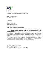
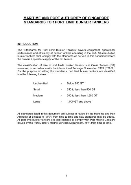
MARITIME AND PORT AUTHORITY OF SINGAPORE<br />
STANDARDS FOR PORT LIMIT BUNKER TANKERS<br />
INTRODUCTION<br />
The “Standards <strong>for</strong> Port Limit Bunker Tankers” covers equipment, operational<br />
per<strong>for</strong>mance and efficiency of <strong>bunker</strong> <strong>tankers</strong> operating in the <strong>port</strong>. All steel-hulled<br />
<strong>bunker</strong> <strong>tankers</strong> shall comply with the <strong>standards</strong> as set out in this document be<strong>for</strong>e<br />
the owners / operators apply <strong>for</strong> the SB licence.<br />
The classification of size of <strong>port</strong> <strong>limit</strong>s <strong>bunker</strong> <strong>tankers</strong> is in Gross Tonnes (GT)<br />
measured in accordance with the international Tonnage Convention 1969 (ITC 69).<br />
For the purpose of setting the <strong>standards</strong>, <strong>port</strong> <strong>limit</strong> <strong>bunker</strong> <strong>tankers</strong> are classified<br />
into the following 4 sizes:<br />
Unclassified - Below 250 GT<br />
Small - 250 to less than 500 GT<br />
Medium - 500 to less than 1,500 GT<br />
Large - 1,500 GT and above<br />
All <strong>standards</strong> listed in this document are subject to review by the Maritime and Port<br />
Authority pf Singapore (<strong>MPA</strong>) from time to time and new <strong>standards</strong> may be added.<br />
All <strong>port</strong> <strong>limit</strong> <strong>bunker</strong> <strong>tankers</strong> are also required to comply with Port Marine Circulars<br />
issued by the Port Master / Marine Services Department, <strong>MPA</strong> from time to time.<br />
1
STANDARDS FOR PORT LIMIT BUNKER TANKERS<br />
All steel-hulled <strong>bunker</strong> <strong>tankers</strong> shall comply with all items of this document<br />
1 Manoeuvring Requirements<br />
1.1 Manoeuvring Flexibility<br />
1.2 Speed<br />
The following propulsion types and requirements are set:<br />
250 to less than 500 GT 500 to less than 1,500 GT 1,500 GT and above<br />
Single Screw or<br />
equivalent<br />
per<strong>for</strong>mance<br />
Twin Screw or Single<br />
Screw with Bow<br />
Thruster(s) or<br />
equivalent per<strong>for</strong>mance<br />
2<br />
Twin Screw with Bow<br />
Thruster(s) or<br />
equivalent per<strong>for</strong>mance<br />
For <strong>bunker</strong> <strong>tankers</strong> of 500 GT and above with twin-screw propulsion, single<br />
screw propulsion with bow thruster(s), twin-screw with bow thruster(s) or<br />
equivalent, a minimum speed of 8 knots measured at 100% of engine rated<br />
load at the time of sea trial under loaded condition shall be attained.<br />
1.3 Engine Reliability<br />
For <strong>bunker</strong> <strong>tankers</strong> of 500 GT and above, the following <strong>standards</strong> shall<br />
apply:<br />
(i) Number of Engine Starting<br />
The minimum number of successful starts attainable by the engine<br />
shall at least meet the requirement set by the approved Classification<br />
Societies.<br />
(ii) Engine Response time<br />
With the <strong>bunker</strong> tanker travelling at a speed of at least 4 knots, the<br />
engine response time from stop to ahead or astern shall not exceed 3<br />
seconds.<br />
(iii) Stopping Distance at Load Draft<br />
The stopping distance at loaded draft with a speed of 5 knots shall<br />
not be greater than three ships’ length.<br />
(iv) Turning Circle in Confined Waters
The <strong>bunker</strong> tanker shall have a turning circle of not more than 1.5<br />
times of its own length, and the time taken to complete a swing of 180<br />
degrees from a stationary position shall not exceed 2 minutes.<br />
For <strong>bunker</strong> <strong>tankers</strong> of 5,000 GT and above, the time taken to<br />
complete a swing of 180 degrees from a stationary position shall not<br />
exceed 4 minutes.<br />
(v) Bridge-controlled Propulsion Machinery<br />
2 Pumping Rate<br />
The <strong>bunker</strong> tanker shall have Centralized Bridge Control <strong>for</strong> the main<br />
propulsion system which shall incorporate stopping, reversing and<br />
speed control of the main engine(s).<br />
For marine fuel oil, pumping rates shall be determined at the <strong>bunker</strong> tanker<br />
manifold(s). The <strong>bunker</strong> tanker shall achieve the following minimum<br />
pumping rates when pumping 380cSt fuel [viscosity at 50 degrees<br />
Centigrade (C)] and under the pressure of 7 kg/cm 2 without the use of flowmeter.<br />
250 to less 500 to less 1,500 GT<br />
than 500 GT than 1,500 GT and above<br />
300 cu m/hour 500 cu m/hour 800 cu m/hour<br />
For marine diesel and marine gas oil, pumping rates shall be measured in<br />
relation of the deadweight of the <strong>bunker</strong> tanker. The <strong>bunker</strong> tanker shall<br />
achieve the following minimum <strong>standards</strong>:<br />
3 Pipeline Outlets<br />
Deadweight Standards<br />
400 - 1000 tonnes Within 4 hours<br />
1001 – 2000 tonnes Within 5 hours<br />
2001 – 3000 tonnes Within 6 hours<br />
More than 3000 tonnes 800 cu m/hour<br />
The <strong>bunker</strong> tanker manifold(s) shall be fitted with ANSI 150 flange or<br />
equivalent.<br />
3
4 Loading Rate<br />
4.1 For marine fuel oil, the <strong>bunker</strong> tanker shall achieve the following minimum<br />
loading rates when receiving 380cSt fuel [viscosity at 50 degrees Centigrade<br />
(C)] and under the pressure of 7 kg/cm 2 :<br />
250 to less 500 to less 1,500 GT<br />
than 500 GT than 1,500 GT and above<br />
300 cu m/hour 500 cu m/hour 800 cu m/hour<br />
For marine diesel and marine gas oil, loading rates shall be measured in<br />
relation to the deadweight of the <strong>bunker</strong> tanker. The <strong>bunker</strong> tanker shall<br />
achieve the following <strong>standards</strong>:<br />
4.2 Air-pipes<br />
Deadweight Standards<br />
400 - 1000 tonnes Within 4 hours<br />
1001 – 2000 tonnes Within 5 hours<br />
2001 – 3000 tonnes Within 6 hours<br />
More than 3000 tonnes 800 cu m/hour<br />
All cargo tanks’ air-pipes shall be sized according to the loading rate and<br />
shall comply with the approved Classification Societies’ requirements.<br />
5 Bunker Boom<br />
All <strong>bunker</strong> <strong>tankers</strong> of 250 GT and above shall have <strong>bunker</strong> boom fitted. The<br />
<strong>bunker</strong> boom shall meet the following <strong>standards</strong>:<br />
(i) Pneumatically or hydraulically operated with a safe working pressure<br />
of 10 kg/cm 2 and can be operated by one man.<br />
(ii) The minimum safe working load shall commensurate with the size of<br />
the boom.<br />
(iii) For non-flow <strong>bunker</strong> boom having <strong>bunker</strong> hose attached, lifting bridles<br />
and saddles shall be provided at suitable positions along the boom to<br />
sup<strong>port</strong> the hose and prevent it from bending.<br />
6 Product Segregation<br />
4
If more than one grade of <strong>bunker</strong>s are carried, it is recommended that<br />
double - valve segregation at the pump room and at the manifold(s) between<br />
grades be incorporated. In addition, the <strong>bunker</strong> tanker shall comply with the<br />
following:<br />
(i) has segregated tanks to minimise product contamination.<br />
(ii) has two main cargo systems.<br />
7 Manifold Size<br />
7.1 The <strong>bunker</strong> tanker shall have at least the following standard manifold sizes:<br />
250 to less 500 to less 1,500 GT<br />
than 500 GT than 1,500 GT and above<br />
100 mm dia. 150 mm dia. 200 mm dia.<br />
7.2 The main manifold(s) shall be located at the mid-ship to facilitate loading<br />
and supply.<br />
8 Manifold Drip/Spill Pan<br />
8.1 The manifold(s) of the <strong>bunker</strong> tanker shall be fitted with drip spill pan to<br />
contain any oil spill.<br />
8.2 Gutter plate shall also be provided on the main deck to contain any oil spill<br />
on deck.<br />
9 Reducers <strong>for</strong> Hose Connection<br />
The <strong>bunker</strong> tanker shall carry Japanese Industrial Standards (JIS) and<br />
American National Standards Institute (ANSI) standard reducers and<br />
adaptors on board to accommodate the different sizes of <strong>bunker</strong> manifold<br />
flanges on the receiving vessels. The sizes of the reducers and adaptors<br />
carried would vary according to the gross tonnage (GT) of the <strong>tankers</strong> as<br />
follows:<br />
500 GT and below 501 to 1,500 GT Above 1,500 GT<br />
80 mm and 3-inch 80 mm and 3-inch 100 mm and 4-inch<br />
100 mm and 4-inch 100 mm and 4-inch 125 mm and 5-inch<br />
125 mm and 5-inch 125 mm and 5-inch 150 mm and 6-inch<br />
150 mm and 6-inch 150 mm and 6-inch 200 mm and 8-inch<br />
- 200 mm and 8-inch 250 mm and 10-inch<br />
5
10 Bunker Hoses<br />
Bunker hoses shall meet the following <strong>standards</strong>:<br />
(i) Corrugated flexible hoses with spring coils having a working pressure<br />
of 10 kg/cm 2 , or<br />
(ii) Composite rubber rein<strong>for</strong>ced type with steel rings having a working<br />
pressure of 10 kg/cm 2.<br />
(iii) Be subjected to a pressure test based on PSB (Ex-SISIR) or<br />
equivalent specifications twice every 5 years. The period between<br />
the two tests shall not exceed 3 years.<br />
(iv) Be visually inspected by an approved Classification Society during<br />
the annual survey of the <strong>bunker</strong> tanker.<br />
11 Bunker Quantity Control - Cargo Measurement System<br />
The <strong>bunker</strong> tanker shall have the following document and equipment <strong>for</strong><br />
measuring the quantity of <strong>bunker</strong>s:<br />
11.1 Tank Calibration Tables<br />
(i) The <strong>bunker</strong> tanker tanks shall be calibrated and certified by an<br />
approved Classification Society or a surveying company acceptable<br />
to <strong>MPA</strong>. An original certified copy of the tank calibration tables shall<br />
be kept onboard.<br />
(ii) The tank calibration tables shall contain the following: -<br />
(a) name and SB licence number of the <strong>bunker</strong> tanker;<br />
(b) list /trim correction;<br />
(c) cargo tanks measurement;<br />
(d) reference height of every cargo tank;<br />
(e) name and stamp of the company which calibrated the tanks;<br />
(f) date of calibration;<br />
(g) page number on every page; and<br />
(h) tank capacity plan of the <strong>bunker</strong> tanker.<br />
6
(iii) The tank calibration tables shall be sealed and properly bound to<br />
prevent any unauthorised tampering.<br />
(iv) The <strong>bunker</strong> tanker shall only carry its latest certified tank calibration<br />
tables <strong>for</strong> verification by the vessel receiving <strong>bunker</strong>s and by the<br />
relevant authority. An identical copy of the tank calibration tables<br />
shall have been deposited with <strong>MPA</strong>.<br />
(v) Should there be any change in the tank capacity of a <strong>bunker</strong> tanker,<br />
the owner and/or operator of the <strong>bunker</strong> tanker shall not carry out any<br />
delivery of <strong>bunker</strong>s until new tank calibration tables <strong>for</strong> the affected or<br />
modified tanks, which comply with the requirements mentioned in<br />
items 11.1 (i) to 11.1 (iv) above, are placed onboard the <strong>bunker</strong><br />
tanker and a true copy of the same, with each page certified,<br />
deposited with the <strong>MPA</strong>.<br />
11.2 Sounding Pipe<br />
(i) Each sounding pipe of the cargo tank shall have a reference height<br />
which shall be clearly stated in the tank calibration tables.<br />
(ii) A template stating the reference height shall also be permanently<br />
fitted onto every sounding pipe of the cargo tank.<br />
11.3 Ullage and Temperature Measuring Devices<br />
(i) The <strong>bunker</strong> tanker shall carry at least one set of <strong>port</strong>able steel<br />
gauging tape approved by ASTM with a 150 mm (6”) weight attached<br />
to one end.<br />
(ii) The <strong>bunker</strong> tanker shall carry at least one set of API/ASTM/IP<br />
approved thermometer on board <strong>for</strong> taking temperature of the oil.<br />
(iii) The latest ASTM-IP Petroleum Measurement Table 54B and Table<br />
56 shall be available on board <strong>for</strong> calculation of <strong>bunker</strong> volume.<br />
11.4 Automatic gauging (Level or Volume) (Optional)<br />
If automatic gauging system is fitted as a supplement to the manual tank<br />
sounding / ullaging system, the following <strong>standards</strong> shall apply:<br />
(i) The system shall be able to provide remote oil temperature readings<br />
to allow <strong>for</strong> volumetric correction of the <strong>bunker</strong> quantity.<br />
(ii) Every cargo tank shall be installed with one level and multiple<br />
temperature sensors. The sensors shall preferably be located at the<br />
after-bulkheads of the tanks.<br />
7
(iii) The system may also be connected to a computer having sounding,<br />
volume and weight calculations with specific gravity and temperature<br />
corrections.<br />
11.5 High Level Alarm<br />
For <strong>bunker</strong> <strong>tankers</strong> which have their keels laid on or after 1 Jun 94, high<br />
level alarm shall be provided <strong>for</strong> the cargo tanks.<br />
11.6 Flow - meter (Optional)<br />
If a flow-meter is used <strong>for</strong> measurement of the <strong>bunker</strong> quantity, the following<br />
<strong>standards</strong> shall apply:<br />
(i) The flow-meter shall have an accuracy of plus or minus 0.2%.<br />
(ii) Instructions on the flow-meter volumetric calculation shall be available<br />
<strong>for</strong> reference.<br />
(iii) A certificate of verification issued by the Weights and Measures<br />
Office, Singapore, <strong>for</strong> the flow-meter shall be carried on board.<br />
(iv) The seal of the flow-meter by the Weight & Measures Office shall be<br />
intact.<br />
(v) The flow-meter shall be calibrated at least once in every 12 months.<br />
11.7 Plans and Diagrams<br />
(i) General layout plan of the <strong>bunker</strong> tanker shall be conspicuously<br />
displayed on board.<br />
(ii) Tank capacity plan, Piping Diagram and Trim and Stability Tables<br />
shall be available on board <strong>for</strong> inspection by any party concerned.<br />
12 Bunker Quality Control<br />
The <strong>bunker</strong> tanker shall be equipped with proper sampling equipment as<br />
described below.<br />
12.1 Sampling Equipment<br />
(i) The <strong>bunker</strong> tanker shall be equipped with the sampling equipment as<br />
per SS 600's requirements:<br />
a. A sampling probe extends across the full diameter of the<br />
sampler. The end of the sampling probe shall be closed and the wall<br />
per<strong>for</strong>ated with 5mm diameter holes spaced 20mm apart throughout<br />
its length. A needle valve, with provision <strong>for</strong> sealing, shall be fitted at<br />
8
the bottom of the sampling probe outside the sampler to control the<br />
rate at which a continuous drip sample can be drawn. This shall also<br />
serve as a stop valve <strong>for</strong> the sampling. The sampling probe shall be<br />
detachable <strong>for</strong> cleaning and inspection.<br />
b. A weather-tight sampling container having a capacity of not<br />
less than four litres which can be security sealed.<br />
(ii) An illustration of the sampling equipment is shown in the Appendix 1.<br />
12.2 Automatic Sampling Equipment<br />
(i) Automatic sampling equipment installed on board the <strong>bunker</strong> tanker<br />
shall be approved by the relevant authority <strong>for</strong> usage.<br />
(ii) The automatic sampling equipment shall be capable of obtaining a<br />
sample during the entire <strong>bunker</strong> process.<br />
(iii) Where the sample is automatically divided into 4 or more individual<br />
one-litre sample bottles simultaneously, the sampling equipment must<br />
be capable of filling the individual sample bottles to the same level.<br />
The sample bottles should be at least 80 percent full at the end of the<br />
<strong>bunker</strong> delivery.<br />
13 Navigation Equipment/Charts/Nautical Publications<br />
(i) The <strong>bunker</strong> tanker shall have a compass fitted at the main steering<br />
position <strong>for</strong> the helmsman to steer.<br />
(ii) A second compass or other appropriate equipment shall be fitted <strong>for</strong><br />
taking bearings if the compass mentioned in item 13 (i) above is not<br />
suitable <strong>for</strong> this purpose.<br />
(iii) Appropriate nautical instruments, adequate and updated charts and<br />
other nautical publications including the latest “Singapore Tide Tables<br />
and Port In<strong>for</strong>mation” <strong>for</strong> the intended voyage shall be carried on<br />
board.<br />
14 Signaling Equipment/Document<br />
(i) The <strong>bunker</strong> tanker shall have the following signaling equipment /<br />
document on board:<br />
(ii) Full complement of flags and pendants.<br />
(iii) A copy of the International Code of signals.<br />
(iv) A daylight signaling lamp.<br />
9
(v) A ship whistle<br />
15 Communication Equipment<br />
The <strong>bunker</strong> tanker shall be equipped with a radiotelephone which is capable<br />
of operating in the International Maritime Mobile VHF Radiocommunication<br />
Service in the 156-174 MHZ and on such channels as may be specified by<br />
the Port Master from time to time.<br />
16 Other Standards<br />
16.1 Identification Marks<br />
(i) The licence number of the <strong>bunker</strong> tanker shall be painted in large<br />
letters on each side of the bow against a contrasting background and<br />
carved on, cut in, or centre punched into the main beam.<br />
(ii) The licence number of the <strong>bunker</strong> tanker shall also be painted or<br />
carved in large letters on each side of the navigating bridge and on<br />
the bridge front <strong>for</strong> easy identification purposes.<br />
(iii) The minimum height (with pro<strong>port</strong>ionate breadth and thickness) of the<br />
letters and numbers comprising the licence number of the <strong>bunker</strong><br />
tanker at the bow shall be as follows:<br />
Thickness<br />
Length of of Letters<br />
Bunker Tanker Height Breadth and Numbers<br />
Between 5 & 20m 20 cm 15 cm 4 cm<br />
Above 20 m 30 cm 20 cm 5 cm<br />
16.2 Lighting<br />
(i) The <strong>bunker</strong> tanker shall be fitted with adequate safe lighting to cover<br />
the area of the <strong>bunker</strong> tanker, <strong>bunker</strong> manifold connection and hose<br />
handling equipment.<br />
(ii) The minimum illumination at night shall be at least 50 lux at the<br />
<strong>bunker</strong> manifold(s).<br />
16.3 Fender<br />
The <strong>bunker</strong> tanker shall have proper fender system to minimise damage to<br />
the receiving vessel during <strong>bunker</strong>ing.<br />
16.4 Anti Oil-pollution Equipment<br />
10
The <strong>bunker</strong> tanker shall carry anti oil-pollution equipment and a minimum of<br />
400 litres of approved dispersants at all time.<br />
16.5 Operational Safety<br />
The <strong>bunker</strong> tanker shall have on board a copy of the International Safety<br />
Guide <strong>for</strong> Oil Tankers & Terminals (ISGOTT).<br />
- End -<br />
PORT MASTER<br />
MARINE SERVICES DEPARTMENT<br />
MARITIME AND PORT AUTHORITY OF SINGAPORE<br />
11<br />
Updated as at 22 Apr 2008
Appendix 1<br />
(In<strong>for</strong>mative)<br />
Diagrams of sampling equipment<br />
Design of sampling equipment - Example 1<br />
12
Design of sampling equipment - Example 2<br />
This sampling equipment should only be used <strong>for</strong> sample collection if Chapter One of SS 600,<br />
clause 1.11.4.2 is applicable.<br />
NOTE – Alternative design of sampling equipment with provisions <strong>for</strong> sealing if approved in advance by the<br />
implementing authority shall also be acceptable.<br />
13