SDB-103 Small Diameter Beveler and FF 206 Flange ... - EH Wachs
SDB-103 Small Diameter Beveler and FF 206 Flange ... - EH Wachs
SDB-103 Small Diameter Beveler and FF 206 Flange ... - EH Wachs

You also want an ePaper? Increase the reach of your titles
YUMPU automatically turns print PDFs into web optimized ePapers that Google loves.
E.H. <strong>Wachs</strong><br />
600 Knightsbridge Parkway<br />
Lincolnshire, IL 60069<br />
www.ehwachs.com<br />
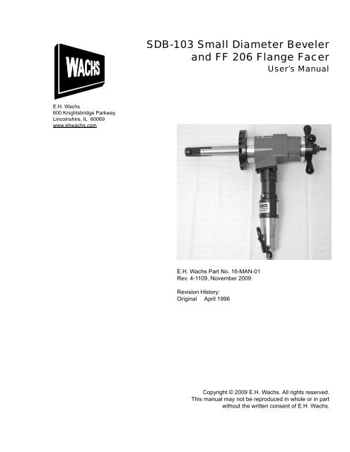
<strong>SDB</strong>-<strong>103</strong> <strong>Small</strong> <strong>Diameter</strong> <strong>Beveler</strong><br />
<strong>and</strong> <strong>FF</strong> <strong>206</strong> <strong>Flange</strong> Facer<br />
User’s Manual<br />
E.H. <strong>Wachs</strong> Part No. 16-MAN-01<br />
Rev. 4-1109, November 2009<br />
Revision History:<br />
Original April 1996<br />
Copyright © 2009 E.H. <strong>Wachs</strong>. All rights reserved.<br />
This manual may not be reproduced in whole or in part<br />
without the written consent of E.H. <strong>Wachs</strong>.
<strong>SDB</strong>-<strong>103</strong> <strong>Small</strong> <strong>Diameter</strong> <strong>Beveler</strong> <strong>and</strong> <strong>FF</strong> <strong>206</strong> <strong>Flange</strong> Facer<br />
Part No. 16-MAN-01, Rev. 4-1109 E.H. <strong>Wachs</strong>
Table of Contents<br />
Table of Contents<br />
Chapter 1: About This Manual . . . . . . . . . . . . . . . . . . . . . . . . . . . . . . . . . . . . . . . . . . . . . . . . . 1<br />
Purpose of This Manual . . . . . . . . . . . . . . . . . . . . . . . . . . . . . . . . . . . . . . . . . . . . . . . . . . . . . . . . . 1<br />
How to Use The Manual . . . . . . . . . . . . . . . . . . . . . . . . . . . . . . . . . . . . . . . . . . . . . . . . . . . . . . . . 1<br />
Symbols <strong>and</strong> Warnings . . . . . . . . . . . . . . . . . . . . . . . . . . . . . . . . . . . . . . . . . . . . . . . . . . . . . . . . . 2<br />
Manual Updates <strong>and</strong> Revision Tracking . . . . . . . . . . . . . . . . . . . . . . . . . . . . . . . . . . . . . . . . . . . . 3<br />
Chapter 2: Safety . . . . . . . . . . . . . . . . . . . . . . . . . . . . . . . . . . . . . . . . . . . . . . . . . . . . . . . . . . . . . 5<br />
Operator Safety . . . . . . . . . . . . . . . . . . . . . . . . . . . . . . . . . . . . . . . . . . . . . . . . . . . . . . . . . . . . . . . 5<br />
Safety Symbols . . . . . . . . . . . . . . . . . . . . . . . . . . . . . . . . . . . . . . . . . . . . . . . . . . . . . . . . . . . . 6<br />
Protective Equipment Requirements . . . . . . . . . . . . . . . . . . . . . . . . . . . . . . . . . . . . . . . . . . . . 7<br />
Safety Labels . . . . . . . . . . . . . . . . . . . . . . . . . . . . . . . . . . . . . . . . . . . . . . . . . . . . . . . . . . . . . . . . . 7<br />
Chapter 3: Introduction to the Equipment . . . . . . . . . . . . . . . . . . . . . . . . . . . . . . . . . . . . . . . . 9<br />
<strong>SDB</strong> <strong>103</strong> <strong>Small</strong> <strong>Diameter</strong> <strong>Beveler</strong> . . . . . . . . . . . . . . . . . . . . . . . . . . . . . . . . . . . . . . . . . . . . . . . . . 9<br />
Optional M<strong>and</strong>rels . . . . . . . . . . . . . . . . . . . . . . . . . . . . . . . . . . . . . . . . . . . . . . . . . . . . . . . . . 11<br />
<strong>FF</strong> <strong>206</strong> <strong>Flange</strong> Facer . . . . . . . . . . . . . . . . . . . . . . . . . . . . . . . . . . . . . . . . . . . . . . . . . . . . . . . . . . 13<br />
Performance Charts . . . . . . . . . . . . . . . . . . . . . . . . . . . . . . . . . . . . . . . . . . . . . . . . . . . . . . . . . . . 15<br />
Specifications . . . . . . . . . . . . . . . . . . . . . . . . . . . . . . . . . . . . . . . . . . . . . . . . . . . . . . . . . . . . . . . . 16<br />
Operating Envelope . . . . . . . . . . . . . . . . . . . . . . . . . . . . . . . . . . . . . . . . . . . . . . . . . . . . . . . . . . . 16<br />
Chapter 4: Assembly, Disassembly, <strong>and</strong> Storage . . . . . . . . . . . . . . . . . . . . . . . . . . . . . . . . . . 21<br />
Storage Checklist . . . . . . . . . . . . . . . . . . . . . . . . . . . . . . . . . . . . . . . . . . . . . . . . . . . . . . . . . . . . . 22<br />
Chapter 5: Operating Instructions . . . . . . . . . . . . . . . . . . . . . . . . . . . . . . . . . . . . . . . . . . . . . . 23<br />
Pre-Operation Checklist . . . . . . . . . . . . . . . . . . . . . . . . . . . . . . . . . . . . . . . . . . . . . . . . . . . . . . . . 23<br />
Setting Up the <strong>SDB</strong> <strong>103</strong> . . . . . . . . . . . . . . . . . . . . . . . . . . . . . . . . . . . . . . . . . . . . . . . . . . . . . . . . 24<br />
Installing the St<strong>and</strong>ard M<strong>and</strong>rel . . . . . . . . . . . . . . . . . . . . . . . . . . . . . . . . . . . . . . . . . . . . . . . 24<br />
Installing the Extension Legs . . . . . . . . . . . . . . . . . . . . . . . . . . . . . . . . . . . . . . . . . . . . . . . . . 26<br />
Installing the <strong>Small</strong> I.D. Conversion Kit . . . . . . . . . . . . . . . . . . . . . . . . . . . . . . . . . . . . . . . . 27<br />
Installing the Independent Fitting M<strong>and</strong>rel . . . . . . . . . . . . . . . . . . . . . . . . . . . . . . . . . . . . . . 28<br />
Mounting the <strong>SDB</strong> <strong>103</strong> . . . . . . . . . . . . . . . . . . . . . . . . . . . . . . . . . . . . . . . . . . . . . . . . . . . . . . . . 31<br />
St<strong>and</strong>ard <strong>and</strong> <strong>Small</strong> I.D. M<strong>and</strong>rels . . . . . . . . . . . . . . . . . . . . . . . . . . . . . . . . . . . . . . . . . . . . . 31<br />
Independent Fitting M<strong>and</strong>rel . . . . . . . . . . . . . . . . . . . . . . . . . . . . . . . . . . . . . . . . . . . . . . . . . 32<br />
Installing <strong>and</strong> Centering on Elbows <strong>and</strong> Bends . . . . . . . . . . . . . . . . . . . . . . . . . . . . . . . . 34<br />
Installing Tooling . . . . . . . . . . . . . . . . . . . . . . . . . . . . . . . . . . . . . . . . . . . . . . . . . . . . . . . . . . 36<br />
Cutting the O.D. . . . . . . . . . . . . . . . . . . . . . . . . . . . . . . . . . . . . . . . . . . . . . . . . . . . . . . . . . . . . . . 37<br />
Cutting the I.D. . . . . . . . . . . . . . . . . . . . . . . . . . . . . . . . . . . . . . . . . . . . . . . . . . . . . . . . . . . . . . . 39<br />
Tips for a Good Finish . . . . . . . . . . . . . . . . . . . . . . . . . . . . . . . . . . . . . . . . . . . . . . . . . . . . . . 40<br />
<strong>FF</strong> <strong>206</strong> <strong>Flange</strong> Facing Setup . . . . . . . . . . . . . . . . . . . . . . . . . . . . . . . . . . . . . . . . . . . . . . . . . . . . 43<br />
Removing the M<strong>and</strong>rel . . . . . . . . . . . . . . . . . . . . . . . . . . . . . . . . . . . . . . . . . . . . . . . . . . . . . 43<br />
Installing the Trip Collar . . . . . . . . . . . . . . . . . . . . . . . . . . . . . . . . . . . . . . . . . . . . . . . . . . . . 44<br />
E.H. <strong>Wachs</strong> Part No. 16-MAN-01, Rev. 4-1109 i
<strong>SDB</strong>-<strong>103</strong> <strong>Small</strong> <strong>Diameter</strong> <strong>Beveler</strong> <strong>and</strong> <strong>FF</strong> <strong>206</strong> <strong>Flange</strong> Facer<br />
<strong>FF</strong> <strong>206</strong> Independent Fitting M<strong>and</strong>rel Setup . . . . . . . . . . . . . . . . . . . . . . . . . . . . . . . . . . . . . . . . . 45<br />
Squaring the <strong>FF</strong> <strong>206</strong> on Squared <strong>Flange</strong> . . . . . . . . . . . . . . . . . . . . . . . . . . . . . . . . . . . . . . . . 47<br />
Squaring the <strong>FF</strong> <strong>206</strong> on Unsquare <strong>Flange</strong> . . . . . . . . . . . . . . . . . . . . . . . . . . . . . . . . . . . . . . . 48<br />
Mounting the <strong>FF</strong> <strong>206</strong> . . . . . . . . . . . . . . . . . . . . . . . . . . . . . . . . . . . . . . . . . . . . . . . . . . . . . . . 48<br />
<strong>FF</strong> <strong>206</strong> <strong>Flange</strong> Facing Operating Procedure . . . . . . . . . . . . . . . . . . . . . . . . . . . . . . . . . . . . . . . . 49<br />
Single-Point Beveling . . . . . . . . . . . . . . . . . . . . . . . . . . . . . . . . . . . . . . . . . . . . . . . . . . . . . . . . . 53<br />
Chapter 6: Routine Maintenance . . . . . . . . . . . . . . . . . . . . . . . . . . . . . . . . . . . . . . . . . . . . . . . 55<br />
Break-In Period . . . . . . . . . . . . . . . . . . . . . . . . . . . . . . . . . . . . . . . . . . . . . . . . . . . . . . . . . . . . . . 55<br />
Periodic Inspection Checklist . . . . . . . . . . . . . . . . . . . . . . . . . . . . . . . . . . . . . . . . . . . . . . . . . . . 56<br />
Lubrication . . . . . . . . . . . . . . . . . . . . . . . . . . . . . . . . . . . . . . . . . . . . . . . . . . . . . . . . . . . . . . . . . . 57<br />
Chapter 7: Service <strong>and</strong> Repair . . . . . . . . . . . . . . . . . . . . . . . . . . . . . . . . . . . . . . . . . . . . . . . . . 59<br />
<strong>SDB</strong> <strong>103</strong> Service . . . . . . . . . . . . . . . . . . . . . . . . . . . . . . . . . . . . . . . . . . . . . . . . . . . . . . . . . . . . . 59<br />
Replacing the Front Bushing . . . . . . . . . . . . . . . . . . . . . . . . . . . . . . . . . . . . . . . . . . . . . . . . . 59<br />
<strong>FF</strong> <strong>206</strong> Service . . . . . . . . . . . . . . . . . . . . . . . . . . . . . . . . . . . . . . . . . . . . . . . . . . . . . . . . . . . . . . . 59<br />
Castle Nut Adjustment . . . . . . . . . . . . . . . . . . . . . . . . . . . . . . . . . . . . . . . . . . . . . . . . . . . . . . 60<br />
Replacing the Feed Screw or Male Tool Slide . . . . . . . . . . . . . . . . . . . . . . . . . . . . . . . . . . . 60<br />
Feed Tension Adjustment . . . . . . . . . . . . . . . . . . . . . . . . . . . . . . . . . . . . . . . . . . . . . . . . . . . 61<br />
Chapter 8: Parts Lists <strong>and</strong> Drawings . . . . . . . . . . . . . . . . . . . . . . . . . . . . . . . . . . . . . . . . . . . 63<br />
Chapter 9: Accessories <strong>and</strong> Spare Parts . . . . . . . . . . . . . . . . . . . . . . . . . . . . . . . . . . . . . . . . . 79<br />
Accessories . . . . . . . . . . . . . . . . . . . . . . . . . . . . . . . . . . . . . . . . . . . . . . . . . . . . . . . . . . . . . . . . . 79<br />
Tooling . . . . . . . . . . . . . . . . . . . . . . . . . . . . . . . . . . . . . . . . . . . . . . . . . . . . . . . . . . . . . . . . . . . . . 80<br />
Chapter 10: Ordering Information . . . . . . . . . . . . . . . . . . . . . . . . . . . . . . . . . . . . . . . . . . . . . 83<br />
Ordering Replacement Parts . . . . . . . . . . . . . . . . . . . . . . . . . . . . . . . . . . . . . . . . . . . . . . . . . . . . 83<br />
Repair Information . . . . . . . . . . . . . . . . . . . . . . . . . . . . . . . . . . . . . . . . . . . . . . . . . . . . . . . . . . . 83<br />
Warranty Information . . . . . . . . . . . . . . . . . . . . . . . . . . . . . . . . . . . . . . . . . . . . . . . . . . . . . . . . . 84<br />
Return Goods Address . . . . . . . . . . . . . . . . . . . . . . . . . . . . . . . . . . . . . . . . . . . . . . . . . . . . . . . . . 84<br />
ii Part No. 16-MAN-01, Rev. 4-1109 E.H. <strong>Wachs</strong>
Chapter 1<br />
About This Manual<br />
PURPOSE OF THIS MANUAL<br />
This manual explains how to operate <strong>and</strong> maintain the<br />
<strong>SDB</strong>-<strong>103</strong> small diameter beveler (<strong>SDB</strong>) <strong>and</strong> <strong>FF</strong> <strong>206</strong> flange<br />
facer. It includes instructions for set-up, operation, <strong>and</strong><br />
maintenance. It also contains parts lists, diagrams, <strong>and</strong> service<br />
information to help you order replacement parts <strong>and</strong><br />
perform user-serviceable repairs.<br />
Before operating the machine, read through this manual <strong>and</strong><br />
become familiar with all instructions.<br />
HOW TO USE THE MANUAL<br />
This manual is organized to help you quickly find the information<br />
you need. Each chapter describes a specific topic on<br />
using or maintaining your equipment.<br />
Each page is designed with two columns. This large column<br />
on the inside of the page contains instructions <strong>and</strong> illustrations.<br />
Use these instructions to operate <strong>and</strong> maintain the<br />
equipment.<br />
The narrower column on the outside contains additional<br />
information such as warnings, special notes, <strong>and</strong> definitions.<br />
Refer to it for safety notes <strong>and</strong> other information.<br />
Chapter 1, About This Manual<br />
In This Chapter<br />
PURPOSE OF THIS MANUAL<br />
HOW TO USE THE MANUAL<br />
SYMBOLS AND WARNINGS<br />
MANUAL UPDATES AND<br />
REVISION TRACKING<br />
Throughout this manual, refer<br />
to this column for warnings,<br />
cautions, <strong>and</strong> notices with<br />
supplementary information.<br />
E.H. <strong>Wachs</strong> Part No. 16-MAN-01, Rev. 4-1109 1
<strong>SDB</strong>-<strong>103</strong> <strong>Small</strong> <strong>Diameter</strong> <strong>Beveler</strong> <strong>and</strong> <strong>FF</strong> <strong>206</strong> <strong>Flange</strong> Facer<br />
WARNING<br />
A WARNING alert with the<br />
safety alert symbol indicates<br />
a potentially hazardous situation<br />
that could result in serious<br />
injury or death.<br />
CAUTION<br />
A CAUTION alert with the<br />
safety alert symbol indicates<br />
a potentially hazardous situation<br />
that could result in<br />
minor or moderate injury.<br />
CAUTION<br />
A CAUTION alert with the<br />
damage alert symbol indicates<br />
a situation that will<br />
result in damage to the<br />
equipment.<br />
IMPORTANT<br />
An IMPORTANT alert with<br />
the damage alert symbol indicates<br />
a situation that may<br />
result in damage to the<br />
equipment.<br />
SYMBOLS AND WARNINGS<br />
The following symbols are used throughout this manual to<br />
indicate special notes <strong>and</strong> warnings. They appear in the outside<br />
column of the page, next to the section they refer to.<br />
Make sure you underst<strong>and</strong> what each symbol means, <strong>and</strong><br />
follow all instructions for cautions <strong>and</strong> warnings.<br />
This is the safety alert symbol. It is used<br />
to alert you to potential personal injury<br />
hazards. Obey all safety messages that<br />
follow this symbol to avoid possible<br />
injury or death.<br />
This is the equipment damage alert<br />
symbol. It is used to alert you to potential<br />
equipment damage situations.<br />
Obey all messages that follow this symbol<br />
to avoid damaging the equipment or<br />
workpiece on which it is operating.<br />
2 Part No. 16-MAN-01, Rev. 4-1109 E.H. <strong>Wachs</strong>
NOTE<br />
This symbol indicates a user note. Notes<br />
provide additional information to supplement<br />
the instructions, or tips for easier<br />
operation.<br />
MANUAL UPDATES AND REVISION TRACKING<br />
Occasionally, we will update manuals with improved operation<br />
or maintenance procedures, or with corrections if necessary.<br />
When a manual is revised, we will update the<br />
revision history on the title page.<br />
You may have factory service or upgrades performed on the<br />
equipment. If this service changes any technical data or<br />
operation <strong>and</strong> maintenance procedures, we will include a<br />
revised manual when we return the equipment to you.<br />
Chapter 1, About This Manual: Manual Updates <strong>and</strong> Revision Tracking<br />
NOTE<br />
A NOTE provides supplementary<br />
information or operating<br />
tips.<br />
Current versions of E.H.<br />
<strong>Wachs</strong> manuals are also<br />
available in PDF format. You<br />
can request an electronic<br />
copy of this manual by emailing<br />
customer service at<br />
sales@ehwachs.com.<br />
E.H. <strong>Wachs</strong> Part No. 16-MAN-01, Rev. 4-1109 3
EU DECLARATION OF CONFORMITY<br />
WITH<br />
COUNCIL DIRECTIVE 98/37/EC<br />
Date Of Issue: April 13, 2005<br />
Directive: Machinery Directive on machinery safety, 98/37/EC<br />
Conforming Machinery: Pipe Beveling & Cut-Off Machines<br />
Model#:16, 56, 66, 70, 71, 72-000-XX<br />
Serial #:<br />
Manufacturer: E. H. <strong>Wachs</strong> Company<br />
600 Knightsbridge Parkway<br />
Lincolnshire, IL<br />
Authorized<br />
Representative:<br />
Harmonized St<strong>and</strong>ards<br />
Referenced or Applied:<br />
60069 USA<br />
Patrick Fuss<br />
Director of International Sales <strong>and</strong> Service<br />
<strong>Wachs</strong> Limited<br />
3 Millbuck Way<br />
Springvale Industrial Estate<br />
S<strong>and</strong>bach, Chesire CW11 3JA<br />
United Kingdom<br />
BS EN 292-1:1991, BS EN 292-2:1991, BS EN 294:1992,<br />
BS EN 349:1998, BS EN 418:1992, BS EN 60204-1:1998<br />
BS EN 982:1996, BS EN 983:1996<br />
Specifications with which Essential Health <strong>and</strong> Safety Requirements of Annex 1 of<br />
Conformity is Declared: the Machinery Directive<br />
We hereby certify that the machinery described above conforms with the essential<br />
health <strong>and</strong> safety requirements of Council Directive 98/37/EC on the approximation of<br />
the laws of the Member States relating to the safety of machinery.<br />
Signed:<br />
Signatory: Pete Mullally<br />
Quality Manager<br />
E. H. <strong>Wachs</strong> Company<br />
6/13/07
Chapter 2<br />
Safety<br />
E.H. <strong>Wachs</strong> takes great pride in designing <strong>and</strong> manufacturing<br />
safe, high-quality products. We make user safety a top<br />
priority in the design of all our products.<br />
Read this chapter carefully before operating the <strong>SDB</strong> <strong>103</strong>/<br />
<strong>FF</strong> <strong>206</strong>. It contains important safety instructions <strong>and</strong> recommendations.<br />
OPERATOR SAFETY<br />
Follow these guidelines for safe operation of the equipment.<br />
• READ THE OPERATING MANUAL. Make sure<br />
you underst<strong>and</strong> all setup <strong>and</strong> operating instructions<br />
before you begin.<br />
• INSPECT MACHINE AND ACCESSORIES.<br />
Before starting the machine, look for loose bolts or<br />
nuts, leaking lubricant, rusted components, <strong>and</strong> any<br />
other physical conditions that may affect operation.<br />
Properly maintaining the machine can greatly decrease<br />
the chances for injury.<br />
• ALWAYS READ PLACARDS AND LABELS. Make<br />
sure all placards, labels, <strong>and</strong> stickers are clearly legible<br />
<strong>and</strong> in good condition. You can purchase replacement<br />
labels from E.H. <strong>Wachs</strong>.<br />
• KEEP CLEAR OF MOVING PARTS. Keep h<strong>and</strong>s,<br />
arms, <strong>and</strong> fingers clear of all rotating or moving parts.<br />
Chapter 2, Safety<br />
In This Chapter<br />
OPERATOR SAFETY<br />
SAFETY LABELS<br />
Look for this symbol<br />
throughout the<br />
manual. It indicates<br />
a personal injury<br />
hazard.<br />
E.H. <strong>Wachs</strong> Part No. 16-MAN-01, Rev. 4-1109 5
<strong>SDB</strong>-<strong>103</strong> <strong>Small</strong> <strong>Diameter</strong> <strong>Beveler</strong> <strong>and</strong> <strong>FF</strong> <strong>206</strong> <strong>Flange</strong> Facer<br />
Always turn machine off before doing any adjustments<br />
or service.<br />
• SECURE LOOSE CLOTHING AND JEWELRY.<br />
Secure or remove loose-fitting clothing <strong>and</strong> jewelry, <strong>and</strong><br />
securely bind long hair, to prevent them from getting<br />
caught in moving parts of the machine.<br />
• KEEP WORK AREA CLEAR. Keep all clutter <strong>and</strong><br />
nonessential materials out of the work area. Only people<br />
directly involved with the work being performed should<br />
have access to the area.<br />
Safety Symbols<br />
This icon is displayed with any safety alert that indicates a<br />
personal injury hazard.<br />
WARNING<br />
This safety alert indicates a potentially hazardous situation<br />
that, if not avoided, could result in death or serious injury.<br />
CAUTION<br />
This safety alert, with the personal injury hazard symbol,<br />
indicates a potentially hazardous situation that, if not<br />
avoided, could result in minor or moderate injury.<br />
6 Part No. 16-MAN-01, Rev. 4-1109 E.H. <strong>Wachs</strong>
Protective Equipment Requirements<br />
For additional information on eye <strong>and</strong> face protection, refer<br />
to Federal OSHA regulations, 29 Code of Federal Regulations,<br />
Section 1910.133., Eye <strong>and</strong> Face Protection <strong>and</strong><br />
American National St<strong>and</strong>ards Institute, ANSI Z87.1, Occupational<br />
<strong>and</strong> Educational Eye <strong>and</strong> Face Protection. Z87.1 is<br />
available from the American National St<strong>and</strong>ards Institute,<br />
Inc., 1430 Broadway, New York, NY 10018.<br />
Hearing protectors are required in high noise areas, 85 dBA<br />
or greater. The operation of other tools <strong>and</strong> equipment in the<br />
area, reflective surfaces, process noises, <strong>and</strong> resonant structures<br />
can increase the noise level in the area. For additional<br />
information on hearing protection, refer to Federal OSHA<br />
regulations, 29 Code of Federal Regulations, Section<br />
1910.95, Occupational Noise Exposure <strong>and</strong> ANSI S12.6<br />
Hearing Protectors.<br />
SAFETY LABELS<br />
WARNING<br />
Always wear impact resistant eye protection<br />
while operating or working near<br />
this equipment.<br />
CAUTION<br />
Personal hearing protection is recommended<br />
when operating or working near<br />
this tool.<br />
The following safety labels are on the <strong>SDB</strong> <strong>103</strong>. If the stickers<br />
are damaged or missing, replace them immediately. See<br />
Chapter 10 for ordering information.<br />
Chapter 2, Safety: Safety Labels<br />
E.H. <strong>Wachs</strong> Part No. 16-MAN-01, Rev. 4-1109 7
<strong>SDB</strong>-<strong>103</strong> <strong>Small</strong> <strong>Diameter</strong> <strong>Beveler</strong> <strong>and</strong> <strong>FF</strong> <strong>206</strong> <strong>Flange</strong> Facer<br />
Figure 2-1. The Caution sticker is on the <strong>SDB</strong> <strong>103</strong> air<br />
motor. Wear ear <strong>and</strong> eye protection while operating<br />
the machine. (Part number 90-401-03.)<br />
Figure 2-2. The Warning sticker is on the <strong>SDB</strong> <strong>103</strong>.<br />
Do not put your h<strong>and</strong>s near the rotating head while<br />
the machine is running. (Part number 66-147-00.)<br />
8 Part No. 16-MAN-01, Rev. 4-1109 E.H. <strong>Wachs</strong>
Chapter 3<br />
Introduction to the<br />
Equipment<br />
<strong>SDB</strong> <strong>103</strong> SMALL DIAMETER BEVELER<br />
The <strong>SDB</strong> <strong>103</strong> is a portable pipe prepping machine that can<br />
face, bevel, compound bevel, J-prep, <strong>and</strong> counterbore open<br />
ended pipe <strong>and</strong> tubing. The h<strong>and</strong>held <strong>SDB</strong> <strong>103</strong> mounts on<br />
the pipe inside diameter (I.D.) using a self-centering m<strong>and</strong>rel<br />
clamp system. It will prep open-ended pipe <strong>and</strong> tubing<br />
from 1.16” to 4.18” I.D. (29.5-106.2 mm), <strong>and</strong> up to 4.5”<br />
(114.3 mm) outside diameter (O.D.).<br />
The <strong>SDB</strong> <strong>103</strong> can be easily installed by one operator in just<br />
a few minutes. Different sized clamp leg sets are provided<br />
to cover the full range of operation. Select <strong>and</strong> install the<br />
appropriate leg set for the pipe you are machining, install<br />
the tooling, <strong>and</strong> mount the machine on the pipe using the<br />
simple drawbar mechanism.<br />
An air or electric motor drives the rotating tool head. The<br />
operator feeds the tooling into the pipe face using a manual<br />
feed h<strong>and</strong>le. A calibrated feed dial allows precise material<br />
removal. The tool head has three tools slots, allowing multiple<br />
facing, beveling, <strong>and</strong> counterboring operations to be<br />
performed simultaneously.<br />
The machine includes all accessories <strong>and</strong> tools necessary<br />
for operation, <strong>and</strong> is shipped in a durable, waterproof storage<br />
case.<br />
Chapter 3, Introduction to the Equipment<br />
In This Chapter<br />
<strong>SDB</strong> <strong>103</strong> SMALL DIAMETER<br />
BEVELER<br />
<strong>FF</strong> <strong>206</strong> FLANGE FACER<br />
PERFORMANCE CHARTS<br />
SPECIFICATIONS<br />
OPERATING ENVELOPE<br />
E.H. <strong>Wachs</strong> Part No. 16-MAN-01, Rev. 4-1109 9
<strong>SDB</strong>-<strong>103</strong> <strong>Small</strong> <strong>Diameter</strong> <strong>Beveler</strong> <strong>and</strong> <strong>FF</strong> <strong>206</strong> <strong>Flange</strong> Facer<br />
Clamp leg sets M<strong>and</strong>rel Tool head Machine body<br />
16-021-01<br />
Air motor<br />
Feed<br />
h<strong>and</strong>le<br />
Drawbar<br />
Figure 3-1. The photo shows the <strong>SDB</strong> <strong>103</strong> components<br />
<strong>and</strong> accessories.<br />
16-021-07 16-021-06 16-021-05<br />
16-021-02<br />
16-021-03<br />
16-021-04<br />
Figure 3-2. The st<strong>and</strong>ard clamp leg sets (identified by<br />
part number) fit the st<strong>and</strong>ard m<strong>and</strong>rel to a range of<br />
pipe <strong>and</strong> tube sizes. See the tables in Chapter 5 for the<br />
clamping range for each leg set.<br />
10 Part No. 16-MAN-01, Rev. 4-1109 E.H. <strong>Wachs</strong>
Facing tool<br />
26-410-02<br />
37.5° Beveling tool<br />
26-411-01<br />
Figure 3-3. The <strong>SDB</strong> st<strong>and</strong>ard tooling allows the<br />
operator to face, bevel, J-prep, <strong>and</strong> counterbore pipe<br />
<strong>and</strong> tube.<br />
Optional M<strong>and</strong>rels<br />
A small-diameter conversion kit (16-401-00) with a<br />
smaller m<strong>and</strong>rel <strong>and</strong> tool head is available. The conversion<br />
kit allows you to install the machine on pipe I.D.s from<br />
0.875” to 1.75” (22.2-31.8 mm).<br />
The st<strong>and</strong>ard <strong>and</strong> small I.D. m<strong>and</strong>rels automatically center<br />
the machine on the I.D. <strong>and</strong> squares it to the centerline of<br />
the pipe. If you need to mount the machine in a pipe that is<br />
on a bend or that has limited I.D. access, an independent<br />
fitting m<strong>and</strong>rel (16-414-00) with dowel-style clamp legs is<br />
available as an option.<br />
With the independent fitting m<strong>and</strong>rel, you can adjust the<br />
machine to be squared to the pipe end surface, rather than<br />
the centerline. (This m<strong>and</strong>rel can also be used to mount the<br />
<strong>FF</strong> <strong>206</strong>.) A squaring plate for aligning the machine during<br />
installation is provided with the m<strong>and</strong>rel.<br />
Chapter 3, Introduction to the Equipment: <strong>SDB</strong> <strong>103</strong> <strong>Small</strong> <strong>Diameter</strong> <strong>Beveler</strong><br />
Counterbore/<br />
facing tool<br />
26-426-00<br />
10° Deburring tool<br />
26-412-02<br />
NOTE<br />
Collet-style m<strong>and</strong>rels are also<br />
available for pipe or tube. Call<br />
E.H. <strong>Wachs</strong> customer service<br />
to discuss your application’s<br />
requirements.<br />
E.H. <strong>Wachs</strong> Part No. 16-MAN-01, Rev. 4-1109 11
<strong>SDB</strong>-<strong>103</strong> <strong>Small</strong> <strong>Diameter</strong> <strong>Beveler</strong> <strong>and</strong> <strong>FF</strong> <strong>206</strong> <strong>Flange</strong> Facer<br />
Figure 3-4. The independent fitting m<strong>and</strong>rel shown in<br />
the photo uses dowel-style clamp legs, shown at right.<br />
Figure 3-5. The squaring plate is used to square the<br />
<strong>SDB</strong> to the pipe face when using the independent fitting<br />
m<strong>and</strong>rel. It is also used for mounting the <strong>FF</strong> <strong>206</strong>.<br />
12 Part No. 16-MAN-01, Rev. 4-1109 E.H. <strong>Wachs</strong>
<strong>FF</strong> <strong>206</strong> FLANGE FACER<br />
With the <strong>FF</strong> <strong>206</strong> conversion kit, the <strong>SDB</strong> <strong>103</strong> can be quickly<br />
converted to a flange facing machine. The <strong>FF</strong> <strong>206</strong> will finish<br />
raised <strong>and</strong> flat flange faces from 2.0” (50.8 mm) I.D. up<br />
to 6.0” (152 mm) O.D. The <strong>FF</strong> <strong>206</strong> can be purchased as a<br />
fully integrated machine, or as a kit to upgrade the <strong>SDB</strong><br />
<strong>103</strong>.<br />
<strong>SDB</strong> <strong>103</strong> with independent fitting<br />
m<strong>and</strong>rel <strong>and</strong> leg sets<br />
Radial tool slide Tool holder<br />
Trip ring Squaring plate<br />
Figure 3-6. The photo shows the components of the<br />
<strong>FF</strong> <strong>206</strong>, including the <strong>SDB</strong> <strong>103</strong> machine.<br />
The <strong>FF</strong> <strong>206</strong> uses a radial-feed tool slide to advance the cutting<br />
tool across the flange face. A starwheel on the slide is<br />
advanced by striking mechanical trips as the machine<br />
rotates. The starwheel turns a feed screw that drives the<br />
slide in the feed direction.<br />
Various finishes can be cut with the <strong>FF</strong> <strong>206</strong> by varying the<br />
number of engaged trips on the trip ring. Finish options<br />
include flange face, record groove, or RMS 63 finish.<br />
Chapter 3, Introduction to the Equipment: <strong>FF</strong> <strong>206</strong> <strong>Flange</strong> Facer<br />
NOTE<br />
The st<strong>and</strong>ard <strong>FF</strong> <strong>206</strong> system<br />
does not contain all components<br />
necessary to use it as<br />
an <strong>SDB</strong> <strong>103</strong>. A conversion kit<br />
(16-420-00) is available to<br />
convert the <strong>FF</strong> <strong>206</strong> to the<br />
<strong>SDB</strong> <strong>103</strong>.<br />
E.H. <strong>Wachs</strong> Part No. 16-MAN-01, Rev. 4-1109 13
<strong>SDB</strong>-<strong>103</strong> <strong>Small</strong> <strong>Diameter</strong> <strong>Beveler</strong> <strong>and</strong> <strong>FF</strong> <strong>206</strong> <strong>Flange</strong> Facer<br />
<strong>SDB</strong> head<br />
mounting<br />
interface<br />
Feed<br />
direction<br />
Tool holder<br />
Feed screw<br />
Starwheel<br />
Figure 3-7. The flange facing slide mounts on the<br />
<strong>SDB</strong> <strong>103</strong> to face flanges.<br />
Figure 3-8. The single-point tool holder with tool<br />
inserts is used for flange facing.<br />
14 Part No. 16-MAN-01, Rev. 4-1109 E.H. <strong>Wachs</strong>
PERFORMANCE CHARTS<br />
The following table is the result of extensive testing. Tests<br />
were performed on carbon steel <strong>and</strong> stainless steel, as well<br />
as exotic materials such as HK40 <strong>and</strong> incalloys.<br />
Nominal<br />
Pipe<br />
Size<br />
3/4”(a)<br />
1”(a)<br />
1 1/4”<br />
1 1/2”<br />
2”<br />
2 1/2”<br />
3”<br />
3 1/2”<br />
Table 1: <strong>SDB</strong> Application <strong>and</strong> Performance<br />
ASA Pipe Schedule Carbon <strong>and</strong> Stainless Steel<br />
5 (b) 10 (b) 40 60 80 120 160<br />
4” (c)<br />
= Effective prepping range<br />
(a) = Limited by m<strong>and</strong>rel I.D.<br />
(b) = <strong>Small</strong> I.D. conversion kit required<br />
(c) = Carbon steel only<br />
Table 2: <strong>FF</strong> <strong>206</strong> <strong>Flange</strong> Surface Trip Chart<br />
Trips Engaged RMS Finish<br />
1 63 RMS<br />
2 125 RMS<br />
4 250 RMS<br />
6 500 RMS<br />
Chapter 3, Introduction to the Equipment: Performance Charts<br />
E.H. <strong>Wachs</strong> Part No. 16-MAN-01, Rev. 4-1109 15
<strong>SDB</strong>-<strong>103</strong> <strong>Small</strong> <strong>Diameter</strong> <strong>Beveler</strong> <strong>and</strong> <strong>FF</strong> <strong>206</strong> <strong>Flange</strong> Facer<br />
SPECIFICATIONS<br />
Machine capacity <strong>SDB</strong> <strong>103</strong>: Pipe <strong>and</strong> tube 0.875” (22.2 mm)<br />
I.D. to 4.5” (114 mm) O.D.<br />
<strong>FF</strong> <strong>206</strong>: <strong>Flange</strong> O.D. from 2.0” (51 mm) to<br />
6.0” (152 mm).<br />
Machining functions<br />
(<strong>SDB</strong> <strong>103</strong>)<br />
Machining functions<br />
(<strong>FF</strong> <strong>206</strong>)<br />
OPERATING ENVELOPE<br />
Facing, O.D. beveling, compound beveling,<br />
J prepping, <strong>and</strong> I.D. counterboring of openend<br />
pipe <strong>and</strong> tube. Use up to four tools<br />
simultaneously.<br />
Single-point finishing of flat <strong>and</strong> raised<br />
flange faces. Surface finishes include 500<br />
RMS (record groove), 250 RMS, 125 RMS,<br />
<strong>and</strong> 63 RMS.<br />
Mounting mechanism I.D.-mounted m<strong>and</strong>rel with adjustable<br />
clamping legs <strong>and</strong> multiple legs sets to<br />
cover full I.D. range. St<strong>and</strong>ard diameter,<br />
small I.D., <strong>and</strong> independent fitting (short<br />
clearance) m<strong>and</strong>rels available.<br />
Drive motors Air motor, 110 V or 220 V electric motor<br />
Air requirements 16-000-01: 35 cfm (991 l/min)<br />
Electrical requirements 16-000-02: 110 VAC, 50-60 Hz, 8.0 A<br />
16-000-03: 220 VAC 50-60 Hz, 4.6 A<br />
Controls Manual clamping, manual axial feed, variable<br />
speed control (air or electric). <strong>FF</strong> <strong>206</strong>:<br />
mechanical radial feed using starwheel/trip<br />
mechanism.<br />
Feed features 2.5” (63.5 mm) maximum axial feed;<br />
0.0625” (1.59 mm) feed per h<strong>and</strong>le revolution.<br />
Indexed feed dial for precise depth.<br />
Tooling St<strong>and</strong>ard <strong>Wachs</strong> form tools for facing, beveling,<br />
<strong>and</strong> counterboring. Single-point<br />
holder with inserts for <strong>FF</strong> <strong>206</strong> flange facing.<br />
High speed steel or carbide. Custom tooling<br />
available.<br />
Dimensions <strong>and</strong> weights See operating envelope drawings in next<br />
section.<br />
The following drawings illustrate the overall dimensions<br />
<strong>and</strong> operating envelopes for the <strong>SDB</strong> <strong>103</strong> with air <strong>and</strong> electric<br />
motors, <strong>and</strong> for the <strong>FF</strong> <strong>206</strong>.<br />
16 Part No. 16-MAN-01, Rev. 4-1109 E.H. <strong>Wachs</strong>
16.75 MAX<br />
425.5<br />
DIMENSIONS IN BRACKETS ARE MILLIMETERS<br />
3.19<br />
81.0<br />
6.26<br />
159.0<br />
4.75<br />
120.7<br />
LEGS SHOWN FULLY RETRACTED<br />
SEE DETAIL-A<br />
5.29<br />
134.5<br />
1.16 MIN<br />
29.6<br />
LEGS SHOWN FULLY RETRACTED<br />
.75<br />
19.1<br />
1.28 REF<br />
32.6<br />
26-410-02<br />
FACING TOOL<br />
1.28<br />
32.6<br />
LEGS SHOWN FULLY EXTENDED<br />
1.57 MAX<br />
39.9<br />
3.36 MAX<br />
85.3<br />
TRAVEL<br />
12.33<br />
313.1<br />
2.46<br />
62.5<br />
DETAIL-A<br />
NOTE:<br />
SEE 16-409-00 FOR EXTENSION<br />
LEG CLAMPING RANGES<br />
3.25 REF<br />
82.5<br />
<strong>SDB</strong> <strong>103</strong> Operating Envelope<br />
Air Drive Configuration, 16-000-01
19.24 REF<br />
488.7<br />
DIMENSIONS IN BRACKETS ARE MILLIMETERS<br />
16.75 MAX<br />
425.5<br />
3.19<br />
81.0<br />
6.26<br />
159.0<br />
4.75<br />
120.7<br />
LEGS SHOWN FULLY RETRACTED<br />
SEE DETAIL-A<br />
5.29<br />
134.5<br />
.75<br />
19.1<br />
1.28 REF<br />
32.6<br />
26-410-02<br />
FACING TOOL<br />
1.16 MIN<br />
29.6<br />
LEGS SHOWN FULLY RETRACTED<br />
6.69<br />
169.8<br />
3.36 MAX<br />
85.3<br />
TRAVEL<br />
1.28<br />
32.6<br />
LEGS SHOWN FULLY EXTENDED<br />
1.57 MAX<br />
39.9<br />
10.07 REF<br />
255.7<br />
2.46<br />
62.5<br />
NOTE:<br />
SEE 16-409-00 FOR EXTENSION<br />
LEG CLAMPING RANGES <strong>SDB</strong> <strong>103</strong> Operating Envelope<br />
DETAIL-A<br />
Electric Drive Configurations<br />
16-000-02 <strong>and</strong> 16-000-03
CLAMPING RANGE<br />
2.43 MAX<br />
61.7<br />
TRAVEL<br />
.87 MIN<br />
22.1<br />
1.11 MAX<br />
28.3<br />
LEGS (16-067-00) SHOWN FULLY RETRACTED<br />
AND<br />
WITHOUT O-RING (16-070-01)<br />
3.13 REF<br />
79.4<br />
2.70 MAX<br />
68.6<br />
TRAVEL<br />
.97 MIN<br />
24.7<br />
1.25MAX<br />
31.7<br />
LEGS (16-068-00) SHOWN FULLY RETRACTED<br />
AND<br />
WITHOUT O-RING (16-070-02)<br />
DIMENSIONS IN BRACKETS ARE MILLIMETERS <strong>SDB</strong> <strong>103</strong> Operating Envelope<br />
<strong>Small</strong> I.D. Conversion Kit, 16-401-00
14.07<br />
357.3<br />
DIMENSIONS IN BRACKETS ARE MILLIMETERS<br />
6.26<br />
159.0<br />
3.19<br />
81.0<br />
.25<br />
6.4<br />
THREAD ENGAGEMENT<br />
ON MANDREL<br />
.33<br />
8.3<br />
.38<br />
9.5<br />
60-702-00<br />
INSERT TOOL<br />
6.19<br />
157.1<br />
R6.63<br />
168.3<br />
SWING<br />
1.77 REF<br />
45.0<br />
12.33<br />
313.1<br />
16-042-00<br />
TOOL HOLDER<br />
3.14<br />
79.9<br />
4.23 MAX<br />
107.3<br />
TRAVEL<br />
3.25 REF<br />
82.5<br />
<strong>FF</strong> <strong>206</strong> Operating Envelope<br />
Air Drive Configuration, 16-000-<strong>FF</strong>
Chapter 4<br />
Assembly,<br />
Disassembly, <strong>and</strong><br />
Storage<br />
The <strong>SDB</strong> <strong>103</strong> comes fully assembled <strong>and</strong> ready to operate.<br />
See the instructions in Chapter 5 for configuring clamp<br />
legs, m<strong>and</strong>rels, <strong>and</strong> tool heads for various applications.<br />
Instructions are also provided for converting the <strong>SDB</strong> <strong>103</strong><br />
to the <strong>FF</strong> <strong>206</strong> flange facer.<br />
The <strong>SDB</strong> <strong>103</strong> <strong>and</strong> <strong>FF</strong> <strong>206</strong> are shipped in custom-configured<br />
storage cases. Keep the machines in their cases when not in<br />
use. Figure 4-1 <strong>and</strong> Figure 4-2 show the machines in their<br />
cases.<br />
<strong>SDB</strong> <strong>103</strong><br />
H<strong>and</strong> tools<br />
Figure 4-1. The photo shows the <strong>SDB</strong> <strong>103</strong> in its case.<br />
Chapter 4, Assembly, Disassembly, <strong>and</strong> Storage<br />
Clamp leg sets<br />
In This Chapter<br />
STORAGE CHECKLIST<br />
E.H. <strong>Wachs</strong> Part No. 16-MAN-01, Rev. 4-1109 21
<strong>SDB</strong>-<strong>103</strong> <strong>Small</strong> <strong>Diameter</strong> <strong>Beveler</strong> <strong>and</strong> <strong>FF</strong> <strong>206</strong> <strong>Flange</strong> Facer<br />
<strong>SDB</strong> <strong>103</strong> machine with independent<br />
fitting m<strong>and</strong>rel<br />
<strong>FF</strong> <strong>206</strong><br />
trip ring<br />
<strong>FF</strong> <strong>206</strong> slide<br />
Tool holder<br />
<strong>and</strong> inserts<br />
Squaring<br />
plate<br />
Figure 4-2. The photo shows the components of the<br />
<strong>FF</strong> <strong>206</strong>, including the <strong>SDB</strong> <strong>103</strong> machine, in its storage<br />
case.<br />
STORAGE CHECKLIST<br />
Clamp leg sets<br />
H<strong>and</strong><br />
tools<br />
Before storing the <strong>SDB</strong> <strong>103</strong> or <strong>FF</strong> <strong>206</strong>, perform the following<br />
maintenance steps:<br />
• Put oil in the air motor oiler, <strong>and</strong> operate the motor for a<br />
few seconds to lubricate its internal components.<br />
• Apply grease to the grease fitting on the <strong>SDB</strong> machine<br />
body.<br />
• Rub a coating of light oil on the drawbar <strong>and</strong> m<strong>and</strong>rel.<br />
• Rub a coating of oil on the feed screw of the <strong>FF</strong> <strong>206</strong><br />
slide.<br />
• Oil the dovetail surfaces on the <strong>FF</strong> <strong>206</strong> slide.<br />
• If you will be storing the machine longer than 30 days,<br />
put desiccant packets in the case to prevent corrosion.<br />
22 Part No. 16-MAN-01, Rev. 4-1109 E.H. <strong>Wachs</strong>
Chapter 5<br />
Operating<br />
Instructions<br />
PRE-OPERATION CHECKLIST<br />
To avoid damaging the equipment, follow these usage<br />
guidelines.<br />
1. Inspect the bore of the rotating head for dirt <strong>and</strong> metal<br />
chips. Clean the bore with compressed air or solvent<br />
as necessary.<br />
2.<br />
Wipe the m<strong>and</strong>rel clean, <strong>and</strong> apply a light coating of<br />
oil.<br />
Figure 5-1. When cleaning the m<strong>and</strong>rel, inspect the<br />
threads for damage.<br />
Chapter 5, Operating Instructions<br />
In This Chapter<br />
PRE-OPERATION CHECKLIST<br />
SETTING UP THE <strong>SDB</strong> <strong>103</strong><br />
MOUNTING THE <strong>SDB</strong> <strong>103</strong><br />
INSTALLING TOOLING<br />
CUTTING THE O.D.<br />
CUTTING THE I.D.<br />
SINGLE-POINT BEVELING<br />
E.H. <strong>Wachs</strong> Part No. 16-MAN-01, Rev. 4-1109 23
<strong>SDB</strong>-<strong>103</strong> <strong>Small</strong> <strong>Diameter</strong> <strong>Beveler</strong> <strong>and</strong> <strong>FF</strong> <strong>206</strong> <strong>Flange</strong> Facer<br />
NOTE<br />
You do not normally need to<br />
remove the m<strong>and</strong>rel from the<br />
machine. Use this procedure<br />
if the m<strong>and</strong>rel has been<br />
removed for service or reconfiguring<br />
the <strong>SDB</strong> <strong>103</strong>.<br />
3.<br />
Lubricate the machine according to the guidelines in<br />
Chapter 6.<br />
SETTING UP THE <strong>SDB</strong> <strong>103</strong><br />
Installing the St<strong>and</strong>ard M<strong>and</strong>rel<br />
These instructions are for installing the st<strong>and</strong>ard m<strong>and</strong>rel on<br />
the <strong>SDB</strong> <strong>103</strong>. For instructions on the optional m<strong>and</strong>rels, see<br />
“Installing the <strong>Small</strong> I.D. Conversion Kit” <strong>and</strong> “Installing<br />
the Independent Fitting M<strong>and</strong>rel” later in this section.<br />
1. Insert the threaded end of the m<strong>and</strong>rel through the<br />
front of the rotating head. Be careful not to damage<br />
the head bushing.<br />
2.<br />
Figure 5-2. If it is not already installed, insert the<br />
m<strong>and</strong>rel through the tool head as shown.<br />
Align the keyway slots of the m<strong>and</strong>rel with the internal<br />
keys of the beveling head.<br />
3. Insert the m<strong>and</strong>rel until it stops. Rotate the feed h<strong>and</strong>le<br />
clockwise to engage the threads into the feed nut, <strong>and</strong><br />
continue feeding until the m<strong>and</strong>rel shaft is approximately<br />
¾” (19 mm) beyond the end cap.<br />
24 Part No. 16-MAN-01, Rev. 4-1109 E.H. <strong>Wachs</strong>
Figure 5-3. Turn the feed h<strong>and</strong>le to thread the m<strong>and</strong>rel<br />
into the machine body<br />
4. Install the draw bar nut, <strong>and</strong> then install <strong>and</strong> tighten<br />
the collar nut. The collar nut captivates the draw bar<br />
nut so the draw bar nut can be turned to exp<strong>and</strong> <strong>and</strong><br />
contract the m<strong>and</strong>rel legs.<br />
Figure 5-4. Tighten the collar nut with finger pressure<br />
to captivate the draw bar nut on the m<strong>and</strong>rel.<br />
Chapter 5, Operating Instructions: Setting Up the <strong>SDB</strong> <strong>103</strong><br />
NOTE<br />
The drawbar nut<br />
<strong>and</strong> the collar nut must be<br />
removed to remove the<br />
m<strong>and</strong>rel from the machine<br />
body.<br />
E.H. <strong>Wachs</strong> Part No. 16-MAN-01, Rev. 4-1109 25
<strong>SDB</strong>-<strong>103</strong> <strong>Small</strong> <strong>Diameter</strong> <strong>Beveler</strong> <strong>and</strong> <strong>FF</strong> <strong>206</strong> <strong>Flange</strong> Facer<br />
Installing the Extension Legs<br />
Install the appropriate leg set to fit the pipe you are machining.<br />
Table 1 gives the I.D. range for each leg set provided<br />
with the <strong>SDB</strong> <strong>103</strong> st<strong>and</strong>ard m<strong>and</strong>rel.<br />
1.<br />
Table 1: St<strong>and</strong>ard M<strong>and</strong>rel Extension Legs<br />
Leg Set Thickness I.D. Range<br />
None N/A 1.16–1.57” (37.8–39.8 mm)<br />
16-021-01 0.218” (5.5 mm) 1.53–1.94” (38.8–49.25 mm)<br />
16-021-02 .405” (10.2 mm) 1.90–2.32” (48.2–58.9 mm)<br />
16-021-03 0.592” (15.0 mm) 2.27–2.69” (57.6–68.7 mm)<br />
16-021-04 0.780” (19.8 mm) 2.64–3.06” (67.0–77.7 mm)<br />
16-021-05 0.968” (24.5 mm) 3.02–3.43” (76.7–87.1 mm)<br />
16-021-06 1.155” (29.3 mm) 3.39–3.81” (86.1–96.7 mm)<br />
16-021-07 1.343” (34.1 mm) 3.76–4.18” (95.5–106.1 mm)<br />
To determine which leg set is required, measure the<br />
work piece pipe I.D. <strong>and</strong> refer to the extension leg<br />
chart in Table 1.<br />
Figure 5-5. Use a scale to measure the I.D. of the<br />
pipe.<br />
26 Part No. 16-MAN-01, Rev. 4-1109 E.H. <strong>Wachs</strong>
2.<br />
3.<br />
Figure 5-6. Each leg set is stamped with a reference<br />
number which corresponds to the pipe I.D. range the<br />
leg set will accommodate.<br />
Select the required extension leg set. The extension<br />
legs each have two captivated screws used to fasten<br />
them to the m<strong>and</strong>rel legs.<br />
Tighten the captivated screws on the extension legs to<br />
attach the extension legs to the m<strong>and</strong>rel legs.<br />
Figure 5-7. Attach the clamp legs to the m<strong>and</strong>rel <strong>and</strong><br />
tighten the 2 screws in each leg.<br />
Installing the <strong>Small</strong> I.D. Conversion Kit<br />
The small I.D. conversion kit (part number 16-401-00)<br />
allows you to install the <strong>SDB</strong> <strong>103</strong> on pipe I.D.s down to<br />
0.875” (22.2 mm). The kit includes a thinner m<strong>and</strong>rel <strong>and</strong> a<br />
tool head with a smaller bore. Use the following procedure<br />
to replace the st<strong>and</strong>ard m<strong>and</strong>rel <strong>and</strong> tool head.<br />
Chapter 5, Operating Instructions: Setting Up the <strong>SDB</strong> <strong>103</strong><br />
E.H. <strong>Wachs</strong> Part No. 16-MAN-01, Rev. 4-1109 27
<strong>SDB</strong>-<strong>103</strong> <strong>Small</strong> <strong>Diameter</strong> <strong>Beveler</strong> <strong>and</strong> <strong>FF</strong> <strong>206</strong> <strong>Flange</strong> Facer<br />
NOTE<br />
When returning<br />
legs to their proper position<br />
in the m<strong>and</strong>rel assembly,<br />
the O ring that secures<br />
them must be in the correct<br />
position prior to reinstalling<br />
the draw bar assembly. The<br />
O ring will not slip over the<br />
end of the draw bar once it<br />
has been installed.<br />
1.<br />
2.<br />
3.<br />
4.<br />
5.<br />
Loosen <strong>and</strong> remove the collar nut <strong>and</strong> drawbar nut on<br />
the st<strong>and</strong>ard m<strong>and</strong>rel.<br />
Turn the feed h<strong>and</strong>le counter-clockwise until you can<br />
remove the st<strong>and</strong>ard m<strong>and</strong>rel through the tool head of<br />
the <strong>SDB</strong> <strong>103</strong>.<br />
Remove the st<strong>and</strong>ard tool head from the <strong>SDB</strong> <strong>103</strong> by<br />
taking out the 4 screws holding it.<br />
Remove the clamp legs on the small I.D. m<strong>and</strong>rel.<br />
Remove the drawbar nut <strong>and</strong> drawbar from the small<br />
I.D. m<strong>and</strong>rel.<br />
6. Insert the small I.D. m<strong>and</strong>rel into the machine body.<br />
Position the m<strong>and</strong>rel so that the keyways are aligned<br />
with the keys in the machine, <strong>and</strong> turn the feed h<strong>and</strong>le<br />
clockwise to thread the m<strong>and</strong>rel into the feed nut.<br />
7.<br />
8.<br />
Slide the small I.D. rotating head over the end of the<br />
m<strong>and</strong>rel. Install it on the machine body with the 4<br />
screws.<br />
Measure the pipe I.D. <strong>and</strong> select the appropriate leg<br />
set <strong>and</strong> o-ring to fit. Make sure to use the correct oring<br />
for the leg set you are using. Refer to Table 2<br />
below.<br />
9. Install the legs onto the drawbar chuck, using the oring<br />
to hold them in place.<br />
10.<br />
Insert the small I.D. drawbar through the m<strong>and</strong>rel <strong>and</strong><br />
re-install the drawbar nut.<br />
Table 2: <strong>Small</strong>-<strong>Diameter</strong> M<strong>and</strong>rel Extension Legs<br />
Leg Set I.D. Range O-Ring<br />
16-067-00 0.875–1.125” (22.2–28.6 mm) 16-070-01<br />
16-068-00 1.00–1.250” (25.4–31.8 mm) 16-070-02<br />
Installing the Independent Fitting M<strong>and</strong>rel<br />
If the pipe you are machining has an obstruction or bend<br />
that does not allow enough room for the st<strong>and</strong>ard m<strong>and</strong>rel to<br />
mount, use the independent fitting m<strong>and</strong>rel instead. Follow<br />
this procedure to install the independent fitting m<strong>and</strong>rel.<br />
28 Part No. 16-MAN-01, Rev. 4-1109 E.H. <strong>Wachs</strong>
The independent fitting m<strong>and</strong>rel is not self-squaring. You<br />
will need to use the squaring plate provided with it to square<br />
the machine to the pipe face.<br />
1. If necessary, remove the st<strong>and</strong>ard m<strong>and</strong>rel from the<br />
<strong>SDB</strong> <strong>103</strong>.<br />
2. Insert the independent fitting m<strong>and</strong>rel through the tool<br />
head until it stops. Position the m<strong>and</strong>rel so that the<br />
keyways are aligned with the keys in the machine, <strong>and</strong><br />
turn the feed h<strong>and</strong>le clockwise to thread the m<strong>and</strong>rel<br />
into the feed nut.<br />
3.<br />
Measure the pipe I.D., <strong>and</strong> select the extension leg set<br />
required. Refer to the extension leg chart in Table 3<br />
below.<br />
Table 3: Independent Fitting M<strong>and</strong>rel Extension Legs<br />
Part Number<br />
(Solid/<br />
adjustable)<br />
16-053-01<br />
N/A<br />
16-053-02/<br />
16-054-02<br />
16-053-03/<br />
16-054-03<br />
16-053-04/<br />
16-054-04<br />
16-053-05/<br />
16-054-05<br />
16-053-06/<br />
16-054-06<br />
16-053-07/<br />
16-054-07<br />
Length<br />
(Solid/<br />
Adjustable)<br />
.0794” (20.1 mm)<br />
N/A<br />
.944” (23.9 mm)<br />
.824” (20.9 mm)<br />
1.094” (27.7 mm)<br />
.974” (24.7 mm)<br />
1.244” (31.5 mm)<br />
1.124” (28.5 mm)<br />
1.394” (35.4 mm)<br />
1.274” (32.3 mm)<br />
1.544” (39.2 mm)<br />
1.424” (66.1 mm)<br />
1.694” (43.0 mm)<br />
1.574” (39.9 mm)<br />
Min. <strong>Diameter</strong> Max. <strong>Diameter</strong><br />
1.95”<br />
(49.5 mm)<br />
2.25”<br />
(57.1 mm)<br />
2.55”<br />
(64.7 mm<br />
2.85”<br />
(72.3 mm)<br />
3.15”<br />
(80.0 mm)<br />
3.45”<br />
(87.6 mm)<br />
3.75”<br />
(95.2 mm)<br />
4. Insert the legs into the m<strong>and</strong>rel head. The adjustment<br />
screw in the adjustable leg must be completely<br />
screwed in.<br />
Chapter 5, Operating Instructions: Setting Up the <strong>SDB</strong> <strong>103</strong><br />
2.31”<br />
(58.6 mm)<br />
2.61”<br />
(66.2 mm)<br />
2.91”<br />
(73.9 mm)<br />
3.21”<br />
(81.5 mm)<br />
3.51”<br />
(89.1 mm)<br />
3.81”<br />
(96.7 mm)<br />
4.11”<br />
(104.3 mm)<br />
E.H. <strong>Wachs</strong> Part No. 16-MAN-01, Rev. 4-1109 29
<strong>SDB</strong>-<strong>103</strong> <strong>Small</strong> <strong>Diameter</strong> <strong>Beveler</strong> <strong>and</strong> <strong>FF</strong> <strong>206</strong> <strong>Flange</strong> Facer<br />
Figure 5-8. Attach the leg adjustment screw to the<br />
adjustable leg <strong>and</strong> screw it in fully.<br />
Figure 5-9. Insert the legs into the independent fitting<br />
m<strong>and</strong>rel.<br />
30 Part No. 16-MAN-01, Rev. 4-1109 E.H. <strong>Wachs</strong>
MOUNTING THE <strong>SDB</strong> <strong>103</strong><br />
St<strong>and</strong>ard <strong>and</strong> <strong>Small</strong> I.D. M<strong>and</strong>rels<br />
1. Insert the m<strong>and</strong>rel chuck into the pipe. For best<br />
results, keep the end of the chuck legs close to the pipe<br />
edge.<br />
2.<br />
3.<br />
Figure 5-10. Insert the m<strong>and</strong>rel into the pipe.<br />
Hold the machine with the m<strong>and</strong>rel at the desired<br />
clamping location.<br />
Rotate the draw bar nut with the supplied wrench to<br />
exp<strong>and</strong> the m<strong>and</strong>rel legs into the I.D. of the pipe. The<br />
chuck legs will automatically center the machine to<br />
the pipe.<br />
Chapter 5, Operating Instructions: Mounting the <strong>SDB</strong> <strong>103</strong><br />
NOTE<br />
The maximum depth of penetration<br />
into the pipe should be<br />
¾” (19 mm) from the rear of<br />
the m<strong>and</strong>rel legs to the pipe<br />
edge. This will allow for a normal<br />
prep <strong>and</strong> still keep the<br />
machine body <strong>and</strong> rotating<br />
head stable.<br />
NOTE<br />
Torque the drawbar<br />
nut to 25 lb-ft.<br />
E.H. <strong>Wachs</strong> Part No. 16-MAN-01, Rev. 4-1109 31
<strong>SDB</strong>-<strong>103</strong> <strong>Small</strong> <strong>Diameter</strong> <strong>Beveler</strong> <strong>and</strong> <strong>FF</strong> <strong>206</strong> <strong>Flange</strong> Facer<br />
NOTE<br />
You can install the independent<br />
fitting m<strong>and</strong>rel in the<br />
pipe before putting it on the<br />
<strong>SDB</strong> <strong>103</strong> or <strong>FF</strong> <strong>206</strong> machine.<br />
The m<strong>and</strong>rel may be easier<br />
to square without the <strong>SDB</strong><br />
<strong>103</strong> attached.<br />
Figure 5-11. Hold the machine in place <strong>and</strong> tighten<br />
the drawbar nut.<br />
Independent Fitting M<strong>and</strong>rel<br />
1.<br />
Set the m<strong>and</strong>rel assembly, with the required leg set<br />
installed, into the pipe.<br />
Figure 5-12. Insert the m<strong>and</strong>rel into the pipe.<br />
32 Part No. 16-MAN-01, Rev. 4-1109 E.H. <strong>Wachs</strong>
2.<br />
3.<br />
Put the squaring plate over the shaft of the m<strong>and</strong>rel<br />
<strong>and</strong> slide it against the head. Pull the m<strong>and</strong>rel back in<br />
the pipe if necessary.<br />
Figure 5-13. Put the squaring plate onto the m<strong>and</strong>rel.<br />
Tighten the set screws in the squaring plate to secure it<br />
to the m<strong>and</strong>rel.<br />
Figure 5-14. Tighten both set screws in the squaring<br />
plate to secure <strong>and</strong> center it to the m<strong>and</strong>rel.<br />
Chapter 5, Operating Instructions: Mounting the <strong>SDB</strong> <strong>103</strong><br />
E.H. <strong>Wachs</strong> Part No. 16-MAN-01, Rev. 4-1109 33
<strong>SDB</strong>-<strong>103</strong> <strong>Small</strong> <strong>Diameter</strong> <strong>Beveler</strong> <strong>and</strong> <strong>FF</strong> <strong>206</strong> <strong>Flange</strong> Facer<br />
4.<br />
5.<br />
Push the m<strong>and</strong>rel into the pipe so that the squaring<br />
plate is pressed tight against the pipe face. Tighten the<br />
drawbar nut while holding the m<strong>and</strong>rel in this position.<br />
Loosen the set screws in the squaring plate <strong>and</strong><br />
remove the plate from the m<strong>and</strong>rel. Check the location<br />
of the legs in the pipe.<br />
Figure 5-15. The m<strong>and</strong>rel legs should be close to the<br />
edge of the pipe.<br />
6. If you need to install the <strong>SDB</strong> <strong>103</strong> or <strong>FF</strong> <strong>206</strong> on the<br />
m<strong>and</strong>rel, slide the tool head over the m<strong>and</strong>rel <strong>and</strong><br />
position the machine to line up the keys <strong>and</strong> the keyway<br />
slots. Turn the feed h<strong>and</strong>le clockwise to thread<br />
the m<strong>and</strong>rel into the machine.<br />
Installing <strong>and</strong> Centering on Elbows <strong>and</strong> Bends<br />
1.<br />
When inserting the m<strong>and</strong>rel into the pipe, position the<br />
adjustable leg at the “short radius bend” side of the<br />
pipe. Make sure the screw on the adjustable leg is<br />
screwed all the way in.<br />
34 Part No. 16-MAN-01, Rev. 4-1109 E.H. <strong>Wachs</strong>
2.<br />
3.<br />
4.<br />
Measurement “B”<br />
Measurement “A”<br />
Figure 5-16. Install the m<strong>and</strong>rel with the adjustable<br />
leg positioned at the short radius bend of the pipe.<br />
Using the squaring plate as described in the previous<br />
section, snug the drawbar nut to hold the m<strong>and</strong>rel in<br />
place. Remove the squaring plate.<br />
Measure the distance over the adjustable leg from the<br />
pipe I.D. to the m<strong>and</strong>rel shaft. Write this number down<br />
as measurement “A”.<br />
At the position 180° across from the adjustable leg,<br />
measure the distance from the pipe I.D. to the m<strong>and</strong>rel<br />
shaft. Write this number down as measurement “B”.<br />
• If the two measurements are close enough for the tolerance<br />
of your application, you do not need to adjust the<br />
centering.<br />
• If you need to re-center the m<strong>and</strong>rel, you will have to<br />
remove the it <strong>and</strong> adjust the screw in the adjustable leg.<br />
• Subtract measurement “A” from measurement “B” <strong>and</strong><br />
divide the result by 2. This is the required adjustment<br />
distance; write it down as “C”.<br />
B<br />
------------<br />
– A<br />
=<br />
C<br />
2<br />
• One turn of the adjustment screw extends the screw by<br />
0.035” (0.89 mm). Divide “C” by this amount to determine<br />
how many turns to adjust the screw.<br />
Chapter 5, Operating Instructions: Mounting the <strong>SDB</strong> <strong>103</strong><br />
NOTE<br />
If the end of the pipe is not<br />
square, you will have to<br />
establish a reference point for<br />
squaring.<br />
E.H. <strong>Wachs</strong> Part No. 16-MAN-01, Rev. 4-1109 35
<strong>SDB</strong>-<strong>103</strong> <strong>Small</strong> <strong>Diameter</strong> <strong>Beveler</strong> <strong>and</strong> <strong>FF</strong> <strong>206</strong> <strong>Flange</strong> Facer<br />
NOTE<br />
This procedure assumes that<br />
the pipe radius is greater at<br />
the “short radius bend” side<br />
of the pipe (measurement<br />
“A”). If the radius is greater<br />
on the other side (measurement<br />
“B”), adjust the leg as<br />
described, but re-install the<br />
m<strong>and</strong>rel with the adjustable<br />
leg in the opposite direction.<br />
5.<br />
6.<br />
7.<br />
8.<br />
Before removing the m<strong>and</strong>rel, attach the squaring<br />
plate to it with the plate firmly against the pipe face.<br />
Loosen the drawbar nut to remove the m<strong>and</strong>rel.<br />
Turn the adjustment screw the number of turns you<br />
calculated above.<br />
With the squaring plate still on the m<strong>and</strong>rel, re-install<br />
the m<strong>and</strong>rel on the pipe <strong>and</strong> tighten the drawbar nut.<br />
Remove the squaring plate <strong>and</strong> repeat the “A” <strong>and</strong> “B”<br />
measurements. If necessary, re-adjust the centering<br />
using the same procedure.<br />
Installing Tooling<br />
Refer to the tool selection chart to select the appropriate<br />
tooling.<br />
1.<br />
Loosen the tool bit wedge screw.<br />
2. Install the facing tool in the rotating head slot.<br />
Direction<br />
of rotation<br />
Align tool with<br />
pipe face<br />
Turns=<br />
---------------<br />
C<br />
0.035<br />
Figure 5-17. Position the tooling so the tool bit completely<br />
contacts the pipe face.<br />
3. Install the beveling tool in the rotating head slot.<br />
4. All tool bits must be installed so the cutting edge is<br />
facing clockwise as seen from the manual feed h<strong>and</strong>le.<br />
36 Part No. 16-MAN-01, Rev. 4-1109 E.H. <strong>Wachs</strong>
5.<br />
Figure 5-18. Direction of rotation is indicated by the<br />
arrow.<br />
Tighten the tool bit wedge screws to secure the tools<br />
in place.<br />
CUTTING THE O.D.<br />
1.<br />
2.<br />
3.<br />
Connect the drive motor to the motor adapter. Tighten<br />
the screws holding the motor in place.<br />
Connect power (air or electric) to the drive motor.<br />
Start the machine, <strong>and</strong> turn the manual feed h<strong>and</strong>le<br />
clockwise until the cutting tools contact the pipe.<br />
Chapter 5, Operating Instructions: Cutting the O.D.<br />
IMPORTANT<br />
An air treatment<br />
module (ATM) with an inline<br />
air oiler / moisture separator<br />
is required for proper<br />
lubrication <strong>and</strong> operation of<br />
the <strong>SDB</strong> air motor. Machine<br />
life can be shortened <strong>and</strong><br />
the warranty can be voided<br />
if an ATM is not used. An<br />
ATM can be purchased<br />
from E.H. <strong>Wachs</strong> or a third<br />
party.<br />
E.H. <strong>Wachs</strong> Part No. 16-MAN-01, Rev. 4-1109 37
<strong>SDB</strong>-<strong>103</strong> <strong>Small</strong> <strong>Diameter</strong> <strong>Beveler</strong> <strong>and</strong> <strong>FF</strong> <strong>206</strong> <strong>Flange</strong> Facer<br />
4.<br />
5.<br />
6.<br />
7.<br />
Figure 5-19. To face the pipe, turn the feed h<strong>and</strong>le<br />
clockwise.<br />
Continue operating the machine until the pipe has a<br />
clean finish.<br />
When the desired finish is complete, turn the feed h<strong>and</strong>le<br />
counter-clockwise to retract the tool away from the<br />
pipe face. Turn off the drive motor.<br />
Retract the tool head fully by turning the manual feed<br />
h<strong>and</strong>le counter-clockwise.<br />
Figure 5-20. Retract the tooling after the operation is<br />
complete by turning the feed h<strong>and</strong>le counter-clockwise.<br />
Disconnect the power source from the drive motor.<br />
38 Part No. 16-MAN-01, Rev. 4-1109 E.H. <strong>Wachs</strong>
CUTTING THE I.D.<br />
1.<br />
Loosen the tool bit wedge screw, <strong>and</strong> remove the facing<br />
tool.<br />
2. Insert the counterbore tool.<br />
3.<br />
Figure 5-21. Insert the counterbore tool but do not<br />
snug the tool bit wedge screws.<br />
Measure the desired counterbore radius <strong>and</strong> l<strong>and</strong><br />
thickness.<br />
Figure 5-22. Use a scale to properly position the<br />
counterbore tool.<br />
Chapter 5, Operating Instructions: Cutting the I.D.<br />
E.H. <strong>Wachs</strong> Part No. 16-MAN-01, Rev. 4-1109 39
<strong>SDB</strong>-<strong>103</strong> <strong>Small</strong> <strong>Diameter</strong> <strong>Beveler</strong> <strong>and</strong> <strong>FF</strong> <strong>206</strong> <strong>Flange</strong> Facer<br />
NOTE<br />
Once the cutting<br />
tools are in place, the<br />
machine can be moved<br />
from one pipe to another of<br />
the same size without<br />
resetting the tool bits. The<br />
same l<strong>and</strong>, bevel, <strong>and</strong> I.D.<br />
bore will be cut on all subsequent<br />
pipes.<br />
4.<br />
5.<br />
Adjust the counterbore tool appropriately.<br />
Loosen the opposite tool bit wedge screw.<br />
6. Insert the I.D. deburring tool into the slot opposite the<br />
beveling tool. Adjust the tool to produce the desired<br />
I.D. size <strong>and</strong> depth.<br />
7.<br />
8.<br />
9.<br />
10.<br />
Tighten both tool bit wedge screws.<br />
Start the machine.<br />
Turn the manual feed h<strong>and</strong>le clockwise until the counterbore<br />
tool contacts the pipe.<br />
Figure 5-23. Run the machine until the desired counterbore<br />
is cut.<br />
Operate the machine until the counterbore is complete.<br />
Tips for a Good Finish<br />
1.<br />
2.<br />
3.<br />
Set the m<strong>and</strong>rel legs as close to the pipe end as possible<br />
while leaving enough space between the edge <strong>and</strong><br />
the clamp legs to complete the operation.<br />
Whenever possible, use cutting oil or coolant. Using<br />
cutting oil or coolant will lengthen tool life.<br />
Feed the tool into the workpiece slowly so tool touchoff<br />
can occur without damage. Once the tool has cut a<br />
40 Part No. 16-MAN-01, Rev. 4-1109 E.H. <strong>Wachs</strong>
4.<br />
5.<br />
6.<br />
full 360 degrees, regulate the speed <strong>and</strong> feed for best<br />
performance. Different materials will require different<br />
feed speeds for optimum performance.<br />
Adjust cutting head RPM depending on the material.<br />
The harder the material, the slower the speed should<br />
be.<br />
Figure 5-24. Turn the air motor throttle clockwise to<br />
increase RPM <strong>and</strong> counter-clockwise to decrease<br />
RPM.<br />
Keep uniform pressure on the feed h<strong>and</strong>le until the<br />
prep is complete.<br />
Retract the tool bits quickly by turning the feed h<strong>and</strong>le<br />
counterclockwise when the prep is finished.<br />
Chapter 5, Operating Instructions: Cutting the I.D.<br />
E.H. <strong>Wachs</strong> Part No. 16-MAN-01, Rev. 4-1109 41
<strong>SDB</strong>-<strong>103</strong> <strong>Small</strong> <strong>Diameter</strong> <strong>Beveler</strong> <strong>and</strong> <strong>FF</strong> <strong>206</strong> <strong>Flange</strong> Facer<br />
7.<br />
Figure 5-25. Turn the feed h<strong>and</strong>le counter-clockwise<br />
as shown to retract the tool bits.<br />
Use the calibrated feed h<strong>and</strong>le for precise cuts.<br />
Figure 5-26. The calibrated feed h<strong>and</strong>le is graduated<br />
in 1/1000” increments.<br />
42 Part No. 16-MAN-01, Rev. 4-1109 E.H. <strong>Wachs</strong>
<strong>FF</strong> <strong>206</strong> FLANGE FACING SETUP<br />
Removing the M<strong>and</strong>rel<br />
1.<br />
2.<br />
3.<br />
4.<br />
Remove the collar nut <strong>and</strong> drawbar nut from the end<br />
of the m<strong>and</strong>rel shaft.<br />
Turn the feed h<strong>and</strong>le counter-clockwise until the m<strong>and</strong>rel<br />
shaft disengages from the feed nut.<br />
Figure 5-27. Remove the drawbar nut before removing<br />
the m<strong>and</strong>rel.<br />
Pull the m<strong>and</strong>rel shaft through the front of the rotating<br />
tool head.<br />
Figure 5-28. Pull the m<strong>and</strong>rel out through the tool<br />
head.<br />
Remove the four screws retaining the rotating tool<br />
head, <strong>and</strong> remove the rotating head.<br />
Chapter 5, Operating Instructions: <strong>FF</strong> <strong>206</strong> <strong>Flange</strong> Facing Setup<br />
NOTE<br />
Take care not to damage the<br />
m<strong>and</strong>rel bushing when<br />
removing the m<strong>and</strong>rel.<br />
E.H. <strong>Wachs</strong> Part No. 16-MAN-01, Rev. 4-1109 43
<strong>SDB</strong>-<strong>103</strong> <strong>Small</strong> <strong>Diameter</strong> <strong>Beveler</strong> <strong>and</strong> <strong>FF</strong> <strong>206</strong> <strong>Flange</strong> Facer<br />
NOTE<br />
Do not remove<br />
the two screws under the<br />
feed screw.<br />
Figure 5-29. Remove the rotating head screws using a<br />
3/16” hex wrench.<br />
Installing the Trip Collar<br />
1. Install the trip collar assembly. The locking screw<br />
must be located close to the air motor housing. Installation<br />
at this position will ensure access to each trip.<br />
2.<br />
Figure 5-30. The trip collar locking screw should be<br />
as close to the air motor housing as possible.<br />
Tighten the trip collar screws.<br />
44 Part No. 16-MAN-01, Rev. 4-1109 E.H. <strong>Wachs</strong>
3.<br />
4.<br />
Chapter 5, Operating Instructions: <strong>FF</strong> <strong>206</strong> Independent Fitting M<strong>and</strong>rel Setup<br />
Place the flange facing module over the machine<br />
housing face <strong>and</strong> align the mounting holes. The felt<br />
washer must be installed on the back of the module.<br />
Figure 5-31. Align the mounting screws with the<br />
rotating head holes.<br />
Tighten the four mounting screws with the provided<br />
hex key set.<br />
5. Insert the m<strong>and</strong>rel assembly into the machine body.<br />
6. Attach the drawbar nut <strong>and</strong> the collar nut to the end of<br />
the m<strong>and</strong>rel shaft.<br />
<strong>FF</strong> <strong>206</strong> INDEPENDENT FITTING MANDREL<br />
SETUP<br />
1.<br />
Measure the flange I.D., <strong>and</strong> select extension leg set<br />
required.<br />
E.H. <strong>Wachs</strong> Part No. 16-MAN-01, Rev. 4-1109 45
<strong>SDB</strong>-<strong>103</strong> <strong>Small</strong> <strong>Diameter</strong> <strong>Beveler</strong> <strong>and</strong> <strong>FF</strong> <strong>206</strong> <strong>Flange</strong> Facer<br />
NOTE<br />
Set up the independent<br />
fitting m<strong>and</strong>rel with<br />
the machine body removed.<br />
Figure 5-32. Measure the I.D. of the flange.<br />
2. Insert legs into m<strong>and</strong>rel head. The leg adjustment<br />
screw must be completely tightened against the leg<br />
face.<br />
Figure 5-33. Attach the leg adjustment screw to the<br />
adjustable leg.<br />
3. Insert the m<strong>and</strong>rel into the flange.<br />
46 Part No. 16-MAN-01, Rev. 4-1109 E.H. <strong>Wachs</strong>
Squaring the <strong>FF</strong> <strong>206</strong> on Squared <strong>Flange</strong><br />
1.<br />
2.<br />
3.<br />
4.<br />
Place the alignment fixture over the m<strong>and</strong>rel shaft.<br />
Slide the alignment fixture firmly against the flange<br />
face.<br />
Chapter 5, Operating Instructions: <strong>FF</strong> <strong>206</strong> Independent Fitting M<strong>and</strong>rel Setup<br />
Tighten the two brass-tipped screws to lock the alignment<br />
fixture in place.<br />
Figure 5-34. The squaring plate automatically<br />
squares the <strong>FF</strong> <strong>206</strong> to the pipe face.<br />
Tighten the drawbar nut.<br />
Figure 5-35. Tighten the drawbar nut to clamp the<br />
m<strong>and</strong>rel in the flange I.D.<br />
E.H. <strong>Wachs</strong> Part No. 16-MAN-01, Rev. 4-1109 47
<strong>SDB</strong>-<strong>103</strong> <strong>Small</strong> <strong>Diameter</strong> <strong>Beveler</strong> <strong>and</strong> <strong>FF</strong> <strong>206</strong> <strong>Flange</strong> Facer<br />
5.<br />
Remove the alignment fixture. The m<strong>and</strong>rel <strong>and</strong><br />
machine are now square to the flange face.<br />
Squaring the <strong>FF</strong> <strong>206</strong> on Unsquare <strong>Flange</strong><br />
If the elbow or bend is not square, establish a reference<br />
point for squaring, <strong>and</strong> then square the machine to that point<br />
using the procedure detailed above.<br />
Mounting the <strong>FF</strong> <strong>206</strong><br />
1.<br />
2.<br />
Slide the machine housing over the threaded end of<br />
the m<strong>and</strong>rel.<br />
Figure 5-36. Install the configured <strong>FF</strong> <strong>206</strong> onto the<br />
m<strong>and</strong>rel.<br />
Turn the feed h<strong>and</strong>le clockwise to engage the m<strong>and</strong>rel<br />
threads.<br />
48 Part No. 16-MAN-01, Rev. 4-1109 E.H. <strong>Wachs</strong>
<strong>FF</strong> <strong>206</strong> FLANGE FACING OPERATING<br />
PROCEDURE<br />
1.<br />
Chapter 5, Operating Instructions: <strong>FF</strong> <strong>206</strong> <strong>Flange</strong> Facing Operating Procedure<br />
Rotate the starwheel <strong>and</strong> retract the tool slide until the<br />
tool holder slot is beyond the O.D. of the flange.<br />
Figure 5-37. Turn the starwheel counter-clockwise to<br />
retract the tool slide past the O.D. of the flange.<br />
2. Install the single point tool holder <strong>and</strong> cutting tool.<br />
Tighten the tool positioning screws.<br />
3.<br />
Figure 5-38. Position the single point cutting tool<br />
with the cutting surface in the direction of rotation.<br />
Time the starwheel by setting it so that one of its<br />
points is perpendicular to the flange face.<br />
NOTE<br />
The independent<br />
fitting m<strong>and</strong>rel with the<br />
alignment fixture is recommended<br />
for optimum centering<br />
<strong>and</strong> squaring.<br />
NOTE<br />
The <strong>FF</strong> <strong>206</strong><br />
rotates clockwise as viewed<br />
from the rear of the<br />
machine. The cutting edge<br />
of the tool must face clockwise<br />
to cut.<br />
E.H. <strong>Wachs</strong> Part No. 16-MAN-01, Rev. 4-1109 49
<strong>SDB</strong>-<strong>103</strong> <strong>Small</strong> <strong>Diameter</strong> <strong>Beveler</strong> <strong>and</strong> <strong>FF</strong> <strong>206</strong> <strong>Flange</strong> Facer<br />
4.<br />
5.<br />
6.<br />
Engage the number of trips required for the desired<br />
surface finish, as described in Table 4.<br />
Table 4: <strong>FF</strong> <strong>206</strong> <strong>Flange</strong> Surface Trip Chart<br />
Trips Engaged RMS Finish<br />
1 63 RMS<br />
2 125 RMS<br />
4 250 RMS<br />
6 500 RMS<br />
Figure 5-39. Flip the trip lever up to engage the trip.<br />
Turn the flange facer by h<strong>and</strong> until the starwheel<br />
reaches an engaged trip. Ensure that the starwheel will<br />
strike the trip as the machine rotates.<br />
Set the tool bit depth by turning the manual feed h<strong>and</strong>le.<br />
Use the calibration label on the machine body to<br />
set the depth precisely.<br />
50 Part No. 16-MAN-01, Rev. 4-1109 E.H. <strong>Wachs</strong>
7.<br />
8.<br />
Chapter 5, Operating Instructions: <strong>FF</strong> <strong>206</strong> <strong>Flange</strong> Facing Operating Procedure<br />
Figure 5-40. Turn the feed h<strong>and</strong>le clockwise to set the<br />
tool bit depth.<br />
Gently snug the set screw on the back of the feed h<strong>and</strong>le<br />
to prevent the machine from feeding radially during<br />
operation.<br />
Figure 5-41. Snug the feed h<strong>and</strong>le set screw to keep<br />
the machine from moving radially when flange facing.<br />
Connect the power supply (air or electric) to the drive<br />
motor.<br />
E.H. <strong>Wachs</strong> Part No. 16-MAN-01, Rev. 4-1109 51
<strong>SDB</strong>-<strong>103</strong> <strong>Small</strong> <strong>Diameter</strong> <strong>Beveler</strong> <strong>and</strong> <strong>FF</strong> <strong>206</strong> <strong>Flange</strong> Facer<br />
9.<br />
10.<br />
11.<br />
12.<br />
Engage the power switch on the motor <strong>and</strong> operate the<br />
machine slowly, making sure the starwheel strikes<br />
each engaged trip.<br />
Operate the machine until the tool feeds in to the O.D.<br />
of the flange surface. Once the tool has cut a full 360<br />
degrees, regulate the speed <strong>and</strong> feed for best performance.<br />
Different materials will require different feed<br />
speeds for optimum performance.<br />
When the flange surface has been completely surfaced,<br />
stop the machine.<br />
Loosen the set screw on the back of the feed h<strong>and</strong>le,<br />
<strong>and</strong> turn the h<strong>and</strong>le counter-clockwise to retract the<br />
tool.<br />
Figure 5-42. Retract the tool by turning the feed h<strong>and</strong>le<br />
counter-clockwise.<br />
52 Part No. 16-MAN-01, Rev. 4-1109 E.H. <strong>Wachs</strong>
SINGLE-POINT BEVELING<br />
Using the <strong>FF</strong> <strong>206</strong>, you can bevel a pipe face with a singlepoint<br />
tool. As the machine rotates <strong>and</strong> the radial feed<br />
advances the tool automatically, turn the manual feed h<strong>and</strong>le<br />
counter-clockwise to withdraw the tool <strong>and</strong> create the<br />
bevel profile. Follow the procedure below, using the information<br />
in Table 5.<br />
1.<br />
2.<br />
Calculate the starting axial position (cutting depth) on<br />
the O.D. of the pipe. Use the “Tangent” value in<br />
Table 5 for the bevel angle you are performing, <strong>and</strong><br />
refer to the drawing in Figure 5-43.<br />
Figure 5-43. Use the pipe thickness <strong>and</strong> the bevel<br />
angle to calculate the starting depth of cut (D). Refer<br />
to Table 5 for tangents of common bevel angles.<br />
The maximum depth you can cut at one time is about<br />
0.300” (7.6 mm). If the number you calculated for D is<br />
greater than that, divide D by 0.300 (or 7.6 if metric)<br />
to determine the number of passes to make.<br />
Cut multiple<br />
passes if D<br />
is too thick<br />
to cut in one<br />
T<br />
D<br />
Pipe<br />
wall<br />
A = Bevel angle<br />
T = Thickness of pipe wall<br />
D = Depth of cut<br />
D = tangent(A) x T<br />
D<br />
A<br />
Starting axial position<br />
Figure 5-44. Cut multiple passes if necessary.<br />
Chapter 5, Operating Instructions: Single-Point Beveling<br />
Pipe O.D.<br />
Pipe I.D.<br />
NOTE<br />
The <strong>FF</strong> <strong>206</strong> with a singlepoint<br />
tool will allow you to<br />
bevel heavier walled pipe<br />
than is possible using the<br />
<strong>SDB</strong> <strong>103</strong> with form tooling.<br />
NOTE<br />
EXAMPLE:<br />
T = 0.75”<br />
A = 20°<br />
D = tangent(20°) x 0.75”<br />
= 0.364 x 0.75” = 0.273”<br />
NOTE<br />
A cutting depth of 0.300” (7.6<br />
mm) is possible under ideal<br />
circumstances. You may<br />
need to cut smaller passes if<br />
the pipe material is especially<br />
hard or if you are cutting a<br />
coarse finish.<br />
E.H. <strong>Wachs</strong> Part No. 16-MAN-01, Rev. 4-1109 53
<strong>SDB</strong>-<strong>103</strong> <strong>Small</strong> <strong>Diameter</strong> <strong>Beveler</strong> <strong>and</strong> <strong>FF</strong> <strong>206</strong> <strong>Flange</strong> Facer<br />
NOTE<br />
EXAMPLE:<br />
To cut a 30° bevel with 6 trips<br />
engaged, you must withdraw<br />
the cutting tool .018” each<br />
time the cutting tool completes<br />
a revolution (turning<br />
the feed h<strong>and</strong>le counterclockwise).<br />
Use the calibrated<br />
feed label on the feed<br />
h<strong>and</strong>le assembly.<br />
3.<br />
4.<br />
Bevel<br />
Angle<br />
5.<br />
6.<br />
7.<br />
8.<br />
9.<br />
10.<br />
11.<br />
Engage the number of trips required for the surface<br />
finish desired. Refer to Table 4 earlier in this chapter.<br />
Refer to Table 5 for the required axial feed rate for the<br />
number of trips you are using. This is the distance you<br />
will need to retract the<br />
Tangent<br />
10 o 0.176<br />
20 o 0.364<br />
30 o 0.577<br />
37.5 o 0.767<br />
Table 5: Axial Feed Rate<br />
Trips Engaged<br />
1 2 3 4<br />
.001”<br />
(.03 mm)<br />
.002”<br />
(.05 mm)<br />
.003”<br />
(.08 mm)<br />
.004”<br />
(.10 mm)<br />
.002”<br />
(.05 mm)<br />
.004”<br />
(.10 mm)<br />
.006”<br />
(.15 mm)<br />
.008”<br />
(.20 mm)<br />
.004”<br />
(.10 mm)<br />
.008”<br />
(.20 mm)<br />
.012”<br />
(.30 mm)<br />
.016”<br />
(.41 mm)<br />
.006”<br />
(.15 mm)<br />
.011”<br />
(.28 mm)<br />
.018”<br />
(.46 mm)<br />
.024”<br />
(.61 mm)<br />
With the <strong>FF</strong> <strong>206</strong> set up as described earlier in this<br />
chapter, turn the feed h<strong>and</strong>le clockwise until the tool<br />
bit just touches the pipe face.<br />
Turn the starwheel on the radial slide counter-clockwise<br />
until the tool bit is past the O.D. of the pipe face.<br />
Turn the feed h<strong>and</strong>le clockwise to advance the tool bit<br />
to the desired cutting depth. If you are cutting multiple<br />
passes, advance it to the position of the first pass.<br />
Start the machine <strong>and</strong> allow the radial slide to advance<br />
until the tool contacts the O.D. of the pipe.<br />
When the tool touches the O.D., start turning the feed<br />
h<strong>and</strong>le counter-clockwise by the required feed rate<br />
from Table 5. Refer to the calibrated feed label.<br />
Operate the machine until the pass is complete <strong>and</strong> the<br />
tool is no longer engaged with the pipe surface. Turn<br />
off the machine.<br />
If you need to cut another pass, reset the tool position<br />
to the required location on the O.D. of the pipe.<br />
Repeat the required number of passes.<br />
54 Part No. 16-MAN-01, Rev. 4-1109 E.H. <strong>Wachs</strong>
Chapter 6<br />
Routine Maintenance<br />
BREAK-IN PERIOD<br />
After the first 10 hours of operation, you should check the<br />
pre-load on the main shaft bearings of the <strong>SDB</strong> <strong>103</strong>, <strong>and</strong><br />
adjust if necessary.<br />
1.<br />
2.<br />
3.<br />
Remove the drive motor from the machine.<br />
Remove the m<strong>and</strong>rel <strong>and</strong> drawbar.<br />
Remove the 4 screws holding the feed housing assembly<br />
(16-302-00) <strong>and</strong> remove the assembly.<br />
Feed housing ass’y<br />
screws (3 shown)<br />
Figure 6-1. Remove the 4 screws attaching the feed<br />
housing assembly.<br />
Chapter 6, Routine Maintenance<br />
In This Chapter<br />
BREAK-IN PERIOD<br />
PERIODIC INSPECTION<br />
CHECKLIST<br />
LUBRICATION<br />
E.H. <strong>Wachs</strong> Part No. 16-MAN-01, Rev. 4-1109 55
<strong>SDB</strong>-<strong>103</strong> <strong>Small</strong> <strong>Diameter</strong> <strong>Beveler</strong> <strong>and</strong> <strong>FF</strong> <strong>206</strong> <strong>Flange</strong> Facer<br />
NOTE<br />
A <strong>Wachs</strong> assembly tool<br />
(AT16-05) is available to<br />
tighten the lock nut.<br />
4. Insert <strong>and</strong> tighten an old tool bit in one slot of the cutting<br />
head.<br />
5.<br />
6.<br />
7.<br />
8.<br />
Set the tool head down onto a bench vise <strong>and</strong> clamp<br />
the tool bit in it to secure the machine body.<br />
Using a spanner wrench, tighten the lock nut while<br />
rotating the main housing until you can feel a slight<br />
drag. Back the lock nut off 1/4 turn.<br />
Remove machine from vise <strong>and</strong> remove the tool bit<br />
from the cutting head.<br />
Replace the feed housing assembly <strong>and</strong> the 4 screws<br />
holding it. Do not tighten the screws yet.<br />
9. Install the drive motor.<br />
10. Insert the m<strong>and</strong>rel into the machine <strong>and</strong> turn the feed<br />
h<strong>and</strong>le clockwise to engage the feed screw through the<br />
feed nut housing. This will ensure proper feed nut<br />
housing alignment with the m<strong>and</strong>rel.<br />
11.<br />
Tighten the 4 screws holding the feed housing assembly.<br />
PERIODIC INSPECTION CHECKLIST<br />
• The bevel gear sets <strong>and</strong> roller bearing should be<br />
inspected every 100 hours of operation <strong>and</strong> lubricated as<br />
needed.<br />
• Check the main shaft bearings every 10 hours of operation.<br />
Remove the air motor, feed housing assembly, <strong>and</strong><br />
four screws. Refer to the exploded view drawings in<br />
Chapter 8 for details.<br />
• Every 10 hours of operation, inspect the front bushing<br />
for signs of wear. Excessive chatter may indicate a worn<br />
front bushing. If necessary, replace the bushing using<br />
the procedure in Chapter 7.<br />
• Inspect the m<strong>and</strong>rel threads for signs of wear every 10<br />
hours of operation. Replace the m<strong>and</strong>rel if the m<strong>and</strong>rel<br />
threads are damaged.<br />
56 Part No. 16-MAN-01, Rev. 4-1109 E.H. <strong>Wachs</strong>
LUBRICATION<br />
1.<br />
2.<br />
3.<br />
4.<br />
The bore of the cutting head, feed nut, <strong>and</strong> m<strong>and</strong>rel<br />
must be kept clean <strong>and</strong> oiled.<br />
Fill the air treatment module with motor oil or antifreeze<br />
motor oil.<br />
Figure 6-2. Apply air motor oil to the air motor daily.<br />
Every 40 hours of operation, flush the air motor with a<br />
solution of three parts cleaning solvent <strong>and</strong> one part<br />
air motor oil. Afterwards, add 1 oz. of air motor oil<br />
into the air line <strong>and</strong> run the air motor for one minute.<br />
The components of the m<strong>and</strong>rel, including the drawbar<br />
<strong>and</strong> clamp legs, should be cleaned <strong>and</strong> oiled every<br />
day of use.<br />
Chapter 6, Routine Maintenance: Lubrication<br />
E.H. <strong>Wachs</strong> Part No. 16-MAN-01, Rev. 4-1109 57
<strong>SDB</strong>-<strong>103</strong> <strong>Small</strong> <strong>Diameter</strong> <strong>Beveler</strong> <strong>and</strong> <strong>FF</strong> <strong>206</strong> <strong>Flange</strong> Facer<br />
Figure 6-3. When cleaning the m<strong>and</strong>rel, inspect the<br />
threads for damage.<br />
58 Part No. 16-MAN-01, Rev. 4-1109 E.H. <strong>Wachs</strong>
Chapter 7<br />
Service <strong>and</strong> Repair<br />
<strong>SDB</strong> <strong>103</strong> SERVICE<br />
Use the following procedures for service <strong>and</strong> repair of the<br />
<strong>SDB</strong> <strong>103</strong> machine components.<br />
Replacing the Front Bushing<br />
Replace the front bushing (16-030-00) if it shows wear or<br />
damage.<br />
1.<br />
2.<br />
Remove the m<strong>and</strong>rel from the machine.<br />
Remove the 4 screws holding the tool head <strong>and</strong><br />
remove the head from the machine.<br />
3. Insert a 1.25” diameter drift pin from the rear of the<br />
main shaft <strong>and</strong> use it drive out the old bushing.<br />
4.<br />
5.<br />
Place the new bushing on a bushing driver (part # 16-<br />
033-00 available from E.H. <strong>Wachs</strong>), <strong>and</strong> press it into<br />
the main shaft until the edge of the bushing is flush<br />
with the front of the shaft.<br />
Replace the tool head <strong>and</strong> the m<strong>and</strong>rel.<br />
<strong>FF</strong> <strong>206</strong> SERVICE<br />
Use the following procedures for service <strong>and</strong> repair of the<br />
components specific to the <strong>FF</strong> <strong>206</strong> flange facer.<br />
Chapter 7, Service <strong>and</strong> Repair<br />
In This Chapter<br />
<strong>SDB</strong> <strong>103</strong> SERVICE<br />
<strong>FF</strong> <strong>206</strong> SERVICE<br />
E.H. <strong>Wachs</strong> Part No. 16-MAN-01, Rev. 4-1109 59
<strong>SDB</strong>-<strong>103</strong> <strong>Small</strong> <strong>Diameter</strong> <strong>Beveler</strong> <strong>and</strong> <strong>FF</strong> <strong>206</strong> <strong>Flange</strong> Facer<br />
Castle Nut Adjustment<br />
If there is excess backlash in the feed screw, adjust it by<br />
adjusting the castle nut tight against the starwheel.<br />
1.<br />
2.<br />
3.<br />
Using a punch, drive out the pin holding the castle nut<br />
on the feed screw.<br />
Figure 7-1. Take out the pin holding the castle nut to<br />
turn the nut.<br />
Turn the castle nut by h<strong>and</strong> clockwise to snug it<br />
against the starwheel.<br />
Replace the pin in the feed screw, holding the castle<br />
nut at the tightest location at which you can put the pin<br />
through it. Tap the pin in with a hammer until it is<br />
flush with the sides of the castle nut.<br />
Replacing the Feed Screw or Male Tool<br />
Slide<br />
If the feed screw or male tool slide is damaged or becomes<br />
worn, replace them according to the following procedure.<br />
1.<br />
2.<br />
Castle<br />
nut<br />
Set the <strong>FF</strong> <strong>206</strong> slide on a workbench or table.<br />
Turn the starwheel counter-clockwise to retract the<br />
male tool slide until it comes off the end of the feed<br />
screw.<br />
60 Part No. 16-MAN-01, Rev. 4-1109 E.H. <strong>Wachs</strong><br />
Pin
3.<br />
4.<br />
5.<br />
6.<br />
Using a punch, drive out the pin holding the castle nut<br />
on the feed screw. (See “Castle Nut Adjustment”<br />
above.)<br />
Turn the castle nut off the end of the feed screw.<br />
Pull the starwheel off the end of the feed screw <strong>and</strong><br />
remove the Woodruff key from the slot in the screw.<br />
Pull the feed screw out through the back of the feed<br />
screw block.<br />
7. Inspect the feed screw <strong>and</strong> male tool slide for damage<br />
to the thread or signs of wear. Replace either or both if<br />
necessary.<br />
8.<br />
To re-assemble the slide, reverse this procedure. Make<br />
sure the castle nut is snug against the starwheel before<br />
re-installing the pin through the feed screw.<br />
Feed Tension Adjustment<br />
An adjustable gib that holds the male tool slide lets you<br />
adjust the feed tension. Check the tension by turning the<br />
starwheel by h<strong>and</strong>. You should be able to turn it, but only by<br />
applying firm pressure. If necessary, adjust the tension using<br />
the following procedure.<br />
Adjustable gib<br />
Adjustment screws (3) Gib screws (3)<br />
1.<br />
Figure 7-2. Adjust the adjustable gib to set the <strong>FF</strong><br />
<strong>206</strong> slide tension.<br />
Turn the starwheel to move the male tool slide to<br />
about the center of the gibs.<br />
Chapter 7, Service <strong>and</strong> Repair: <strong>FF</strong> <strong>206</strong> Service<br />
E.H. <strong>Wachs</strong> Part No. 16-MAN-01, Rev. 4-1109 61
<strong>SDB</strong>-<strong>103</strong> <strong>Small</strong> <strong>Diameter</strong> <strong>Beveler</strong> <strong>and</strong> <strong>FF</strong> <strong>206</strong> <strong>Flange</strong> Facer<br />
2.<br />
3.<br />
4.<br />
5.<br />
6.<br />
7.<br />
8.<br />
On the adjustable gib, loosen the gib screws. Turn<br />
them just enough to crack them loose.<br />
To increase the slide tension, turn the middle adjustment<br />
screw in (clockwise). Turn the screw by a small<br />
amount—no more than 1/4 turn at a time.<br />
To decrease the slide tension, turn the middle adjustment<br />
screw out (counter-clockwise). Turn it by a small<br />
amount—no more than 1/4 turn at a time.<br />
Snug down the center gib screw <strong>and</strong> turn the starwheel<br />
to check the slide tension. If necessary, loosen the center<br />
gib screw <strong>and</strong> re-adjust the center adjustment<br />
screw until the slide tension is correct.<br />
Loosen the center gib screw again <strong>and</strong> turn the starwheel<br />
to move the male tool slide to one end of the<br />
gibs. Use the adjustment screw at that location to set<br />
the tension. Snug the gib screw to check the tension.<br />
Loosen the gib screw by the male tool slide, then turn<br />
the starwheel to move the slide to the other end of the<br />
gib. Repeat the adjustment process using the adjustment<br />
screw at this end of the gib.<br />
Tighten down all gib screws <strong>and</strong> check the tension<br />
along the entire travel of the slide. Re-adjust the tension<br />
at any locations necessary.<br />
62 Part No. 16-MAN-01, Rev. 4-1109 E.H. <strong>Wachs</strong>
Chapter 8<br />
Parts Lists <strong>and</strong><br />
Drawings<br />
The drawings on the following pages include parts lists for<br />
all components. Refer to the drawings <strong>and</strong> part numbers for<br />
identifying <strong>and</strong> ordering replacement parts.<br />
Chapter 8, Parts Lists <strong>and</strong> Drawings<br />
E.H. <strong>Wachs</strong> Part No. 16-MAN-01, Rev. 4-1109 63
<strong>SDB</strong>-<strong>103</strong> <strong>Small</strong> <strong>Diameter</strong> <strong>Beveler</strong> <strong>and</strong> <strong>FF</strong> <strong>206</strong> <strong>Flange</strong> Facer<br />
64 Part No. 16-MAN-01, Rev. 4-1109 E.H. <strong>Wachs</strong>
ITEM PART NUMBER QTY. DESCRIPTION<br />
1 16-005-00 1 HEAD, ROTATING<br />
2 16-025-00 3 WIPER, FELT<br />
3 16-082-00 1 CASE (NOT SHOWN)<br />
4 16-087-00 1 INSERT, FOAM (NOT SHOWN)<br />
5 16-301-00 1 AIR MOTOR ASSEMBLY<br />
6 16-302-00 1 FEED HOUSING ASSEMBLY<br />
7 16-304-00 1 BEARING HOUSING ASSEMBLY<br />
8 16-409-00 1 STD. MANDREL ASSEMBLY, 1.16"-4.18" I.D.<br />
9 16-MAN-01 1 MANUAL (NOT SHOWN)<br />
10 56-099-00 1 LABEL (NOT SHOWN)<br />
11 66-147-00 1 LABEL, WARNING<br />
12 90-050-07 11 SHCS, 1/4-20 X 3/4<br />
13 90-800-02 1<br />
WRENCH, 11/16 COMBINATION<br />
(NOT SHOWN)<br />
14 90-800-06 1<br />
WRENCH, 5/64-1/4 HEX SET<br />
(NOT SHOWN)<br />
WEIGHT: 20.0 LB. [9.1 kg]<br />
8<br />
12<br />
1<br />
2<br />
12<br />
5<br />
7<br />
11<br />
6<br />
<strong>SDB</strong> <strong>103</strong>, Air Drive Configuration<br />
16-000-01<br />
8<br />
12
ITEM PART NUMBER QTY. DESCRIPTION<br />
1 16-005-00 1 HEAD, ROTATING<br />
2 16-025-00 1 WIPER, FELT<br />
3 16-302-00 1 FEED HOUSING ASSEMBLY<br />
4 16-304-00 1 BEARING HOUSING ASSEMBLY<br />
5 16-409-00 1 STD. MANDREL ASSEMBLY, 1.16"-4.18" I.D.<br />
6 WHERE USED 1 <strong>SDB</strong> <strong>103</strong>/3 ELECT. DRIVE ASSEMBLY<br />
7 66-147-00 1 LABEL, WARNING<br />
8 90-050-07 8 SHCS, 1/4-20 X 3/4<br />
9 16-MAN-01 1 MANUAL (NOT SHOWN)<br />
10 16-082-00 1 CASE (NOT SHOWN)<br />
11 16-087-00 1 INSERT, FOAM (NOT SHOWN)<br />
12 56-099-00 1 LABEL (NOT SHOWN)<br />
13 90-800-02 1<br />
WRENCH, 11/16 COMBINATION<br />
(NOT SHOWN)<br />
14 90-800-06 1<br />
WRENCH, 5/64-1/4 HEX SET<br />
(NOT SHOWN)<br />
ITEM<br />
WEIGHT = 24 LB. [10.9 kg]<br />
6<br />
PART NO.<br />
16-416-00<br />
16-416-01<br />
5<br />
-WHERE USED-<br />
DESCRIPTION<br />
<strong>SDB</strong> <strong>103</strong>/3 ELECT. DRIVE ASSEMBLY-110V<br />
<strong>SDB</strong> <strong>103</strong>/3 ELECT. DRIVE ASSEMBLY-220V<br />
8<br />
1<br />
USED ON<br />
16-000-02<br />
16-000-03<br />
2<br />
6<br />
4<br />
7<br />
3<br />
<strong>SDB</strong> <strong>103</strong> Electric Drive Configuration<br />
16-000-02 (110 V) <strong>and</strong> 16-000-03 (220 V)<br />
5<br />
8
13<br />
-WHERE USED-<br />
ITEM PART NUMBER QTY. DESCRIPTION<br />
11<br />
DESCRIPTION<br />
PART NO.<br />
ITEM<br />
4<br />
LABEL, FEED NUT (INCH)<br />
LABEL, FEED NUT (MM)<br />
16-036-00<br />
16-036-01<br />
8<br />
12<br />
1 16-002-00 1 HOUSING, FEED NUT<br />
2 16-008-00 1 COLLAR, KEY<br />
3 16-009-00 2 KEY, MANDREL<br />
4 16-010-00 1 NUT, FEED<br />
5 16-011-00 1 BEARING, FEED NUT<br />
6 16-012-00 1 WASHER<br />
7 16-013-10 1 RETAINING RING, GROUND<br />
8 WHERE USED 1 LABEL, FEED NUT<br />
9 90-040-05 4 SHCS, 10-24 X 1/2<br />
10 90-040-10 4 SHCS, 10-24 X 1<br />
11 90-054-08 4 SSS, 1/4-20 X 7/8<br />
12 90-074-27 1 SSS, 3/8-16 X 3/4 NYLOCK FLAT PT.<br />
13 90-900-64 4 KNOB<br />
8<br />
2<br />
1<br />
5<br />
3<br />
6<br />
7<br />
9<br />
16-302-00, Feed Housing Assembly<br />
10
14<br />
10<br />
ITEM PART NUMBER QTY. DESCRIPTION<br />
1<br />
9<br />
1 16-001-00 1 HOUSING, BEARING<br />
2 16-003-00 1 SHAFT, MAIN<br />
3 16-006-00 1 GEAR, RING<br />
4 16-007-00 1 GEAR, PINION<br />
5 16-027-00 2 CUP, BEARING<br />
6 16-028-00 1 CONE, BEARING<br />
7 16-029-00 1 CONE W/SEAL, BEARING<br />
8 16-030-00 1 BUSHING<br />
9 16-031-00 1 LOCKNUT<br />
10 26-047-00 1 PLATE, NAME<br />
11 26-096-00 1 BEARING<br />
12 26-097-00 1 RETAINING RING, EXTERNAL<br />
13 90-027-07 1 KEY, 1/8 SQ X 3/4<br />
14 90-049-05 4 METAL-TACK<br />
6<br />
3<br />
5<br />
5<br />
7<br />
4<br />
2<br />
11<br />
8<br />
12<br />
16-304-00, Bearing Housing Assembly<br />
13
-WHERE USED-<br />
ITEM PART NUMBER QTY DESCRIPTION<br />
ITEM PART NO. DESCRIPTION<br />
EXTENSION, CHUCK LEG 1.53-1.94 [38.9-49.3mm]<br />
EXTENSION, CHUCK LEG 1.90-2.32 [48.3-58.9mm]<br />
EXTENSION, CHUCK LEG 2.27-2.69 [57.7-68.3mm]<br />
EXTENSION, CHUCK LEG 2.64-3.06 [67.1-77.7mm]<br />
EXTENSION, CHUCK LEG 3.02-3.43 [76.7-87.1mm]<br />
EXTENSION, CHUCK LEG 3.39-3.81 [86.1-96.8mm]<br />
EXTENSION, CHUCK LEG 3.76-4.18 [95.5-106.2mm]<br />
16-021-01<br />
16-021-02<br />
16-021-03<br />
16-021-04<br />
16-021-05<br />
16-021-06<br />
16-021-07<br />
5<br />
1 16-014-00 1 MANDREL<br />
2 16-015-00 1 DRAW BAR, WELDMENT<br />
3 16-019-00 1 COLLAR, NUT<br />
4 16-020-00 3 LEG, CHUCK<br />
5 WHERE USED 3 AS NOTED<br />
6 16-079-00 1 NUT, DRAW BAR<br />
7 90-042-05 3 BHCS, 10-24 X 1/2<br />
3<br />
6<br />
1<br />
2<br />
7<br />
4<br />
5<br />
16-409-00, St<strong>and</strong>ard M<strong>and</strong>rel Assembly
ITEM PART NUMBER QTY. DESCRIPTION<br />
1 16-004-00 1 HEAD, ROTATING<br />
2 16-025-00 1 WIPER, FELT<br />
3 90-050-07 4 SHCS, 1/4-20 X 3/4<br />
3<br />
2<br />
3.125<br />
1<br />
16-400-00, St<strong>and</strong>ard Tool Head
-WHERE USED-<br />
ITEM PART NUMBER QTY. DESCRIPTION<br />
DESCRIPTION<br />
PART NO.<br />
ITEM<br />
12<br />
1 16-050-00 1 MANDREL, ELBOW<br />
2 16-051-00 1 CONE<br />
3 16-052-00 1 ROD, DRAW<br />
4 16-055-00 2 SCREW, 3/8 DIA. ADJUSTABLE<br />
5 16-056-00 1 NUT, DRAW BAR<br />
6 16-057-00 1 FIXTURE, ALIGNMENT<br />
7 16-058-00 1 BLOCK, WOOD LEG (NOT SHOWN)<br />
8 16-059-00 1 STICKER, LEG RANGE (NOT SHOWN)<br />
9 90-059-28 2 SSS, 1/4-20 X 3/4 BRASS TIP<br />
10 90-800-68 1<br />
WRENCH, 3/4 X 5/8 BOX RATCHET<br />
(NOT SHOWN)<br />
11 90-904-03 3 SSS, 6-32 X 3/8 NYLON<br />
12 WHERE USED 2 LEG<br />
13 WHERE USED 1 LEG, ADJUSTABLE<br />
4<br />
5<br />
13<br />
LEG (.794)<br />
LEG (.944)<br />
LEG (1.094)<br />
LEG (1.244)<br />
LEG (1.394)<br />
LEG (1.544)<br />
LEG (1.694)<br />
LEG, ADJUSTABLE (.824)<br />
LEG, ADJUSTABLE (.974)<br />
LEG, ADJUSTABLE (1.124)<br />
LEG, ADJUSTABLE (1.274)<br />
LEG, ADJUSTABLE (1.424)<br />
LEG, ADJUSTABLE (1.574)<br />
16-053-01<br />
16-053-02<br />
16-053-03<br />
16-053-04<br />
16-053-05<br />
16-053-06<br />
16-053-07<br />
16-054-02<br />
16-054-03<br />
16-054-04<br />
16-054-05<br />
16-054-06<br />
16-054-07<br />
13<br />
1<br />
11<br />
12<br />
9<br />
3<br />
2<br />
6<br />
16-414-00, Independent Fitting M<strong>and</strong>rel Assembly
ITEM PART NUMBER QTY. DESCRIPTION<br />
7<br />
2<br />
1 16-062-00 1 HEAD, ROTATING-7/8<br />
2 16-063-00 1 MANDREL, 7/8"<br />
3 16-064-00 1 WELDMENT, DRAW BAR<br />
4 16-067-00 3 LEG, .88 - 1.11<br />
5 16-069-00 1 BUSHING<br />
6 16-070-01 1 O-RING (-114) URETHANE SHORE 90<br />
7 16-084-00 1 NUT, DRAW BAR<br />
8 90-050-12 4 SHCS, 1/4-20 X 1-1/4<br />
9 16-068-00 3 LEG, 1 - 1-1/4 (NOT SHOWN)<br />
10 16-070-02 1 O-RING (-116) (NOT SHOWN)<br />
5<br />
8 1<br />
6<br />
3<br />
4<br />
16-401-00, <strong>Small</strong> <strong>Diameter</strong> Conversion Kit
ITEM PART NUMBER QTY. DESCRIPTION<br />
1 16-301-00 1 AIR MOTOR ASSEMBLY<br />
2 16-302-00 1 FEED HOUSING ASSEMBLY<br />
3 16-304-00 1 BEARING HOUSING ASSEMBLY<br />
4 16-404-00 1 SLIDE ASSEMBLY, SINGLE POINT<br />
5 16-414-00 1 <strong>SDB</strong> <strong>103</strong> ELB. MANDREL ASSEMBLY<br />
6 66-147-00 1 LABEL, WARNING<br />
7 90-050-07 7 SHCS, 1/4-20 X 3/4<br />
8 16-MAN-01 1 MANUAL (NOT SHOWN)<br />
9 16-025-00 2 WIPER, FELT (NOT SHOWN-SHIPPED LOOSE)<br />
10 16-082-00 1 CASE (NOT SHOWN)<br />
11 16-087-00 1 INSERT, FOAM (NOT SHOWN)<br />
12 56-099-00 1 LABEL (NOT SHOWN)<br />
13 56-191-00 1 WRENCH, TORX (NOT SHOWN)<br />
14 90-800-02 1<br />
WRENCH, 11/16 COMBINATION<br />
(NOT SHOWN)<br />
15 90-800-06 1<br />
WRENCH, 5/64-1/4 HEX SET<br />
(NOT SHOWN)<br />
WEIGHT: 28.5 LB. [12.9 kg]<br />
5<br />
4<br />
7<br />
1<br />
3<br />
6<br />
2<br />
16-000-<strong>FF</strong>, <strong>FF</strong> <strong>206</strong> <strong>Flange</strong> Facer Assembly<br />
7
ITEM PART NUMBER QTY. DESCRIPTION<br />
1 16-025-00 2 WIPER, FELT<br />
2 16-037-00 1 PLATE, MOUNTING<br />
3 16-038-00 1 SLIDE, MALE<br />
4 16-039-00 1 PLATE, BACKING<br />
5 16-040-00 1 SCREW, FEED<br />
6 16-041-00 1 BLOCK, FEED SCREW<br />
7 16-042-00 1 HOLDER, TOOL<br />
8 16-044-00 6 TRIP<br />
9 16-045-00 1 WELDMENT, TRIP COLLAR<br />
10 43-022-00 2 BEARING, FEED SCREW<br />
11 52-140-00 6 PLUNGER, BALL<br />
12 56-066-00 2 GIB<br />
13 56-067-00 1 WHEEL, STAR<br />
14 56-190-00 2 SCREW, INSERT<br />
15 60-702-00 1 INSERT, TOOL<br />
16 90-019-43 1 KEY, 3/32 X 3/8 WOODRU<strong>FF</strong><br />
17 90-026-55 1 1/8" X 1/2" PIN<br />
18 90-050-07 5 SHCS, 1/4-20 X 3/4<br />
19 90-050-08 6 SHCS, 1/4-20 X 7/8<br />
20 90-050-10 2 SHCS, 1/4-20 x 1<br />
21 90-054-05 7 SSS, 1/4-20 X 1/2<br />
22 90-057-53 6 SHSB, 1/4 X 3/8<br />
23 90-075-07 1 NUT, 3/8-24 SLOTTED<br />
24 90-800-31 1<br />
WRENCH, 9/16 COMBINATION<br />
(NOT SHOWN)<br />
25 90-800-69 1<br />
WRENCH, T-15 TORX<br />
(NOT SHOWN)<br />
19<br />
7<br />
12<br />
20<br />
15<br />
16<br />
17<br />
14<br />
6<br />
5<br />
3<br />
19<br />
23<br />
10<br />
10<br />
13<br />
21<br />
18<br />
12<br />
4<br />
2<br />
1<br />
22<br />
21<br />
16-404-00, <strong>FF</strong> <strong>206</strong> <strong>Flange</strong> Facer Slide Assembly<br />
8<br />
18<br />
11<br />
9
2<br />
1<br />
ITEM PART NUMBER QTY. DESCRIPTION<br />
4<br />
1 16-005-00 1 HEAD, ROTATING<br />
2 16-025-00 1 WIPER, FELT<br />
3 16-409-00 1 STD. MANDREL ASSEMBLY, 1.16"-4.18" I.D.<br />
4 90-050-07 4 SHCS, 1/4-20 X 3/4<br />
3<br />
4.750<br />
16-420-00, <strong>FF</strong> <strong>206</strong> to <strong>SDB</strong> <strong>103</strong> Conversion Kit
1<br />
ITEM PART NUMBER QTY. DESCRIPTION<br />
1 16-026-00 1 MOTOR, AIR<br />
2 16-060-00 1 VALVE, SPEED CONTROL<br />
3 90-029-43 1 KEY, 1/8 X 1/2 8630 ALLOY STL WOODRU<strong>FF</strong><br />
4 90-058-58 1 NIPPLE, 1/4 HEX H.P.<br />
5 90-401-02 1 LABEL, PRESSURE<br />
6 90-401-03 1 LABEL, EAR AND EYE PROTECTION<br />
3<br />
5<br />
4<br />
6<br />
16-301-00, Air Motor Assembly<br />
2
-WHERE USED-<br />
ITEM PART NUMBER QTY. DESCRIPTION<br />
ITEM PART NO. DESCRIPTION<br />
MOTOR, METABO 110V<br />
MOTOR, METABO 220V<br />
20-031-00<br />
30-031-01<br />
8<br />
8<br />
9<br />
10<br />
4<br />
1<br />
1 11-<strong>103</strong>-00 1 GEARBOX, PLANETARY OUTPUT<br />
2 16-073-00 1 HOUSING, GEAR<br />
3 16-074-00 1 SHAFT, OUTPUT<br />
4 16-075-00 1 HOUSING, REAR<br />
5 16-076-00 1 RING, RETAINING<br />
6 16-077-00 1 RING, RETAINING<br />
7 16-078-00 1 BEARING<br />
8 WHERE USED 1 MOTOR, METABO<br />
9 26-126-01 1 COUPLING, INPUT<br />
10 90-020-15 7 SHCS #8-32 x 1.375<br />
11 90-027-07 1 KEY, 1/8 SQ X 3/4<br />
12 90-050-08 3 SHCS, 1/4-20 X 7/8<br />
13 90-060-12 1 SHCS, 5/16-18 X 1-1/4<br />
14 90-401-03 1 LABEL, EAR AND EYE PROTECTION<br />
11<br />
13<br />
3<br />
6<br />
7<br />
14<br />
5<br />
12<br />
2<br />
<strong>SDB</strong> <strong>103</strong> Electric Drive Assembly<br />
16-416-00, 110 V<br />
16-416-01, 220 V
ITEM PART NUMBER QTY. DESCRIPTION<br />
2<br />
7<br />
5<br />
6<br />
1 05-061-01 1 HOSE WHIP, 6-FT. X 1/2" DIA.<br />
2 26-080-00 1 WELDMENT, A.T.M.<br />
3 26-083-00 1 FILTER REGULATOR-LUBRICATOR (FRL)<br />
4 90-050-07 2 SHCS, 1/4-20 X 3/4<br />
5 90-055-01 2 NUT, 1/4-20 HEX<br />
6 90-055-52 2 WASHER, 1/4 SPLIT RING<br />
7 90-055-56 4 WASHER, #12 FLAT<br />
8 90-400-01 2 LABEL, WACHS CIRCLE LOGO 1.625<br />
8<br />
3<br />
7<br />
4<br />
1<br />
26-407-00, Air Caddy Assembly
Chapter 9<br />
Accessories <strong>and</strong><br />
Spare Parts<br />
ACCESSORIES<br />
The following accessories are available for the <strong>SDB</strong> <strong>103</strong><br />
<strong>and</strong> <strong>FF</strong> <strong>206</strong>.<br />
Table 1: ADB <strong>103</strong>/<strong>FF</strong> <strong>206</strong> Accessories<br />
Part Number Description<br />
16-401-00 <strong>Small</strong> diameter conversion kit<br />
16-414-00 Independent fitting m<strong>and</strong>rel<br />
16-411-00 Collet m<strong>and</strong>rel for pipe (special order)<br />
16-412-00 Collet m<strong>and</strong>rel for tube (special order)<br />
16-421-00 <strong>FF</strong> <strong>206</strong> conversion kit (for <strong>SDB</strong> <strong>103</strong>)<br />
16-420-00 <strong>SDB</strong> <strong>103</strong> conversion kit (for <strong>FF</strong> <strong>206</strong>)<br />
16-404-00 <strong>FF</strong> <strong>206</strong> tool slide<br />
72-405-01 3.25” diameter wedgelock tool head<br />
72-405-00 4.25” diameter wedgelock tool head<br />
16-301-00 Air drive<br />
16-416-00 110 V electric drive<br />
16-416-01 220 V electric drive<br />
26-407-00 Air treatment module<br />
Chapter 9, Accessories <strong>and</strong> Spare Parts<br />
In This Chapter<br />
ACCESSORIES<br />
TOOLING<br />
E.H. <strong>Wachs</strong> Part No. 16-MAN-01, Rev. 4-1109 79
<strong>SDB</strong>-<strong>103</strong> <strong>Small</strong> <strong>Diameter</strong> <strong>Beveler</strong> <strong>and</strong> <strong>FF</strong> <strong>206</strong> <strong>Flange</strong> Facer<br />
TOOLING<br />
The following tables list tooling for the <strong>SDB</strong> <strong>103</strong> <strong>and</strong> <strong>FF</strong><br />
<strong>206</strong>.<br />
Table 2: <strong>SDB</strong> <strong>103</strong> Facing Tools<br />
Part Number Description<br />
26-410-02 St<strong>and</strong>ard facing tool<br />
26-410-03 High-range facing tool<br />
26-410-04 Carbide-tipped facing tool<br />
26-SPT-01<br />
Custom high-speed steel facing tool—customer<br />
specifications required<br />
Table 3: <strong>SDB</strong> <strong>103</strong> Beveling Tools<br />
Part Number Description<br />
26-411-01 37.5° low-range bevel tool<br />
26-411-02 37.5° medium-range bevel tool<br />
26-411-03 37.5° high-range bevel tool<br />
26-411-04 37.5° carbide bevel tool<br />
26-713-00<br />
26-SPT-02<br />
26-SPT-06<br />
20°, 3/32” radius “J” bevel tool for 1.35” to 4.00” I.D.<br />
(use with 26-410-02 facing tool for 0.030” l<strong>and</strong><br />
extension)<br />
Custom single-angle bevel tool—customer specifications<br />
required<br />
Custom high-speed steel “J” bevel tool—customer<br />
specifications required<br />
26-413-01 37.5° universal low-range beveling <strong>and</strong> facing tool<br />
26-413-02 37.5° universal high-range beveling <strong>and</strong> facing tool<br />
26-SPT-04<br />
Custom high-speed steel beveling tool—customer<br />
specifications required<br />
Table 4: <strong>SDB</strong> <strong>103</strong> I.D. Counterboring Tools<br />
Part Number Description<br />
26-412-01 Low-range I.D. deburring tool<br />
26-412-02 Medium-range I.D. deburring tool<br />
80 Part No. 16-MAN-01, Rev. 4-1109 E.H. <strong>Wachs</strong>
26-412-03 High-range I.D. deburring tool<br />
26-426-00 30° taper counterbore <strong>and</strong> facing tool<br />
26-SPT-03<br />
26-SPT-05<br />
Custom high-speed steel I.D. deburring tool—customer<br />
specifications required<br />
Custom high-speed steel counterboring tool—customer<br />
specifications required<br />
Table 5: <strong>FF</strong> <strong>206</strong> Single-Point Tooling<br />
Part Number Description<br />
16-701-00<br />
Table 4: <strong>SDB</strong> <strong>103</strong> I.D. Counterboring Tools<br />
Part Number Description<br />
<strong>Flange</strong> facing carbide insert tool holder kit (includes<br />
tool wrench <strong>and</strong> 5 tool inserts)<br />
60-702-00 Carbide insert for beveling <strong>and</strong> flange facing<br />
See the drawing on the next page for the single-point tool<br />
holder.<br />
Chapter 9, Accessories <strong>and</strong> Spare Parts: Tooling<br />
E.H. <strong>Wachs</strong> Part No. 16-MAN-01, Rev. 4-1109 81
<strong>SDB</strong>-<strong>103</strong> <strong>Small</strong> <strong>Diameter</strong> <strong>Beveler</strong> <strong>and</strong> <strong>FF</strong> <strong>206</strong> <strong>Flange</strong> Facer<br />
ITEM PART NUMBER QTY. DESCRIPTION<br />
1 16-042-00 1 HOLDER, TOOL<br />
2 56-190-00 2 SCREW, INSERT<br />
3 56-191-00 1 WRENCH, TORX (NOT SHOWN)<br />
4 60-702-00 5 INSERT, TOOL<br />
2<br />
4<br />
16-701-00, <strong>Flange</strong> Facing Insert Holder<br />
82 Part No. 16-MAN-01, Rev. 4-1109 E.H. <strong>Wachs</strong><br />
1
Chapter 10<br />
Ordering Information<br />
To place an order, request service, or get more detailed<br />
information on any E.H. <strong>Wachs</strong> products, call us at one of<br />
the following numbers:<br />
U.S. 800-323-8185<br />
International: 847-537-8800<br />
You can also visit our Web site at:<br />
www.ehwachs.com<br />
ORDERING REPLACEMENT PARTS<br />
When ordering parts, refer to the drawings <strong>and</strong> parts lists in<br />
Chapter 8. Please provide the part description <strong>and</strong> part<br />
number for all parts you are ordering.<br />
REPAIR INFORMATION<br />
Please call us for an authorization number before returning<br />
any equipment for repair or factory service. We will advise<br />
you of shipping <strong>and</strong> h<strong>and</strong>ling. When you send the equipment,<br />
please include the following information:<br />
• Your name/company name<br />
• Your address<br />
• Your phone number<br />
• A description of the problem or the work to be done.<br />
Chapter 10, Ordering Information<br />
In This Chapter<br />
ORDERING REPLACEMENT<br />
PARTS<br />
REPAIR INFORMATION<br />
WARRANTY INFORMATION<br />
RETURN GOODS ADDRESS<br />
E.H. <strong>Wachs</strong> Part No. 16-MAN-01, Rev. 4-1109 83
<strong>SDB</strong>-<strong>103</strong> <strong>Small</strong> <strong>Diameter</strong> <strong>Beveler</strong> <strong>and</strong> <strong>FF</strong> <strong>206</strong> <strong>Flange</strong> Facer<br />
Before we perform any repair, we will estimate the work<br />
<strong>and</strong> inform you of the cost <strong>and</strong> the time to complete it.<br />
WARRANTY INFORMATION<br />
Enclosed with the manual is a warranty card. Please fill out<br />
the registration card <strong>and</strong> return to E.H. <strong>Wachs</strong>. Retain the<br />
owner’s registration record <strong>and</strong> warranty card for your<br />
information.<br />
RETURN GOODS ADDRESS<br />
Return equipment for repair to the following address.<br />
E.H. <strong>Wachs</strong><br />
600 Knightsbridge Parkway<br />
Lincolnshire, Illinois 60069 USA<br />
84 Part No. 16-MAN-01, Rev. 4-1109 E.H. <strong>Wachs</strong>
600 Knightsbridge Parkway Lincolnshire, IL 60069<br />
847-537-8800 www.ehwachs.com