impedance, short circuit currents, and voltage distortion - Controlled ...
impedance, short circuit currents, and voltage distortion - Controlled ...
impedance, short circuit currents, and voltage distortion - Controlled ...
You also want an ePaper? Increase the reach of your titles
YUMPU automatically turns print PDFs into web optimized ePapers that Google loves.
APPLICATION NOTES Ultra-K - UK#16<br />
IMPEDANCE, SHORT CIRCUIT CURRENTS,<br />
AND VOLTAGE DISTORTION<br />
General<br />
This application note addresses<br />
the significance of the output<br />
<strong>impedance</strong> of a transformer to<br />
<strong>short</strong> <strong>circuit</strong> <strong>currents</strong> <strong>and</strong> <strong>voltage</strong><br />
harmonic development on<br />
Impedance<br />
Impedance is the total current<br />
limiting factor ( i=e/z ). For<br />
transformers it is more convenient<br />
to rate the <strong>impedance</strong> as a<br />
Fault Current<br />
The purpose of investigating the<br />
<strong>impedance</strong> is the relationship to<br />
the transformer’s <strong>short</strong> <strong>circuit</strong><br />
current (Isc) <strong>and</strong> the associated<br />
<strong>circuit</strong> breaker fault clearing<br />
capacity. According to the NEC, a<br />
<strong>circuit</strong> breaker’s rating must be at<br />
least 120% of it’s full rated current.<br />
In the following example, the<br />
<strong>circuit</strong> breaker ampacity is<br />
1000amps (833 x 120%) with a<br />
minimum asymmetrical interrupt<br />
current (AIC) capacity of 16,666<br />
amps. Had the output <strong>impedance</strong><br />
been 3%, the AIC would be<br />
27,757 amps; requiring a more<br />
Voltage Distortion<br />
An economical balance must be<br />
obtained when considering the<br />
<strong>impedance</strong>. Lowering the<br />
<strong>impedance</strong> minimizes the <strong>voltage</strong><br />
waveform <strong>distortion</strong>, typically<br />
lowering the K-rating <strong>and</strong><br />
increasing the fault current. This<br />
is not a concern below 150 KVA,<br />
the applied source.<br />
A quality transformer is made with<br />
copper coils wrapped around steel<br />
laminate. The coils characteristics<br />
percentage than use its absolute<br />
value. Typical <strong>impedance</strong> is<br />
between 2% <strong>and</strong> 9%. At very low<br />
values of <strong>impedance</strong> (below 3%) a<br />
expensive <strong>circuit</strong> breaker but<br />
rendering a much more efficient<br />
system. Therefore, a high output<br />
<strong>impedance</strong> transformer requires a<br />
lower AIC <strong>circuit</strong> breaker,<br />
however, the compromise<br />
contributes to <strong>voltage</strong> <strong>distortion</strong>.<br />
The lower cost of the <strong>circuit</strong><br />
breaker is minor in comparison to<br />
the cost to correct the <strong>voltage</strong><br />
<strong>distortion</strong>.<br />
however, above 150 KVA, an<br />
abnormally low <strong>impedance</strong><br />
becomes costly <strong>and</strong> difficult to<br />
coordinate the protection devices.<br />
A good compromise is to<br />
incorporate K-rated transformers<br />
with an <strong>impedance</strong> of 3 to 4% <strong>and</strong><br />
operate the transformer at less<br />
include resistance (R) <strong>and</strong><br />
inductive reactance (X). The<br />
<strong>impedance</strong> (Z) is equal to the<br />
vector sum of resistance <strong>and</strong><br />
inductive reactance.<br />
correlation to efficiency can be<br />
established but there is no direct<br />
relationship because the<br />
resistance varies.<br />
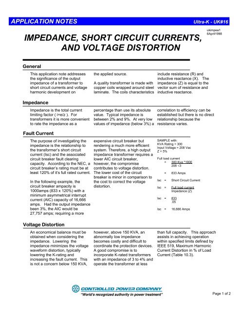
SAMPLE with:<br />
KVA Rating = 300<br />
Input Voltage = 208 Vac<br />
Z = 5%<br />
Full load current<br />
= 300 Kva *1000<br />
208 √3<br />
= 833 Amps<br />
Isc = Short Circuit Current<br />
Isc = Full load current<br />
Impedance (Z)<br />
Isc = 833<br />
.05<br />
Isc = 16,666 Amps<br />
ukimpea1<br />
6April1998<br />
than full capacity. This approach<br />
assists in achieving operation<br />
within specified limits defined by<br />
IEEE 519, Maximum Harmonic<br />
Current Distortion in % of Load<br />
Current (Table 10.3).<br />
Page 1 of 2
The electrical distribution contains<br />
harmonic <strong>currents</strong>, with the 5th<br />
<strong>and</strong> 7th harmonic being<br />
predominant. They cause<br />
additional heating <strong>and</strong> produce a<br />
<strong>voltage</strong> <strong>distortion</strong>. The <strong>voltage</strong><br />
<strong>distortion</strong> produced is related to<br />
the <strong>impedance</strong> (e = iz). In order<br />
to minimize the effects it is<br />
important to keep the <strong>impedance</strong><br />
of the transformer low. IEEE 519<br />
defines the acceptable Total<br />
Dem<strong>and</strong> Distortion (TDD) for an<br />
individual harmonic order which is<br />
based on Isc/IL. (IL= actual load<br />
current)<br />
Summary<br />
Maximum Harmonic Current Distortion in % of IL<br />
Individual Harmonic Order (Odd Harmonics)<br />
I SC / I L


