

Short Circuit Test of HTS Power Cable - ASL
Short Circuit Test of HTS Power Cable - ASL
Short Circuit Test of HTS Power Cable - ASL

You also want an ePaper? Increase the reach of your titles
YUMPU automatically turns print PDFs into web optimized ePapers that Google loves.
<strong>Short</strong> <strong>Circuit</strong> <strong>Test</strong> <strong>of</strong> <strong>HTS</strong> <strong>Power</strong> <strong>Cable</strong><br />
S. Torii, H. Kado, M. Ichikawa, H. Suzuki, M. Yagi and S. Mukoyama<br />
Abstract—The 500 m high temperature superconducting (<strong>HTS</strong>)<br />
cable developed by the Super-ACE project included copper layers<br />
as protection against short circuit current. The design policy was<br />
that liquid nitrogen would not vaporize when it was exposed to the<br />
short circuit current <strong>of</strong> 31.5 kA with 0.5 s. In order to establish the<br />
design policy, we have made nine 10 m samples with the same<br />
construction <strong>of</strong> the 500 m <strong>HTS</strong> cable and set three cables in the<br />
liquid nitrogen vessel. Both <strong>of</strong> balanced fault <strong>of</strong> 3LG and<br />
unbalanced faults <strong>of</strong> 1LG and 2LG have been set and fault<br />
currents have been applied to the <strong>HTS</strong> cables. After each fault, the<br />
critical current has been measured and we have confirmed no<br />
variation <strong>of</strong> Ic before and after each fault. <strong>HTS</strong> cables have not<br />
been damaged mechanically by the fault current <strong>of</strong> 31.5kA with<br />
0.5 s<br />
Index Terms— <strong>HTS</strong> cable, <strong>Short</strong> circuit current, Protection,<br />
Critical current, Mechanical damage<br />
I. INTRODUCTION<br />
A<br />
<strong>HTS</strong> cable is expected for large capacity and high density<br />
transmission <strong>of</strong> electric power to the urban grid with low<br />
voltage. Therefore, many projects had been conducted in the<br />
world [1-8]. The verification test <strong>of</strong> 500 m <strong>HTS</strong> cable had been<br />
conducted by CRIEPI under the Super-ACE project in Japan<br />
[7-11]. In this test, high stability, potential and reliability <strong>of</strong><br />
<strong>HTS</strong> cable had been verified. A feature <strong>of</strong> 500 m <strong>HTS</strong> cable had<br />
included copper layers as a protection against short circuit<br />
current for both <strong>of</strong> core and shield. In this paper, we described<br />
the short circuit test results with the <strong>HTS</strong> cable.<br />
II. CABLE DESIGN AND SPECIFICATIONS<br />
The 500 m <strong>HTS</strong> cable had been constructed by <strong>HTS</strong> tapes,<br />
electrical insulators and copper conductors. The schematic<br />
construction is shown in Fig. 1. The former was a stranded<br />
cooper hollow conductor with the cross section <strong>of</strong> 250 mm 2 and<br />
outer diameter <strong>of</strong> 28.4 mm, and this former was expected to<br />
play protection <strong>of</strong> core conductor against short circuit current.<br />
On the copper former, 20 <strong>HTS</strong> tapes were wound with 1 layer,<br />
300 mm pitch and the outer diameter <strong>of</strong> 30.9 mm. As an electric<br />
Manuscript received August 28, 2006. This work has been carried out as a<br />
part <strong>of</strong> the Super-ACE (R&D <strong>of</strong> fundamental technologies for superconducting<br />
AC power equipment) project <strong>of</strong> METI, under consignment by NEDO.<br />
S. Torii, H. Kado, M. Ichikawa and H. Suzuki are with Central Research<br />
Institute <strong>of</strong> Electric <strong>Power</strong> Industry (CRIEPI), Yokosuka, Japan (phone:<br />
+81-46-856-2121; fax: +81-46-856-3540; e-mail: tori@criepi.denken.or.jp,<br />
kado@criepi.denken.or.jp, michi@criepi.denken.or.jp and<br />
ksuzuki@criepi.denken.or.jp ).<br />
M. Yagi and S. Mukoyama are with Furukawa Electric Co. Ltd., Japan<br />
(e-mail: m-yagi@ch.furukawa.co.jp and mukoyama@ch.furukawa.co.jp ).<br />
insulator, laminated papers were wrapped with 8 mm thickness<br />
and the outer diameter <strong>of</strong> 49.3 mm. Then 30 <strong>HTS</strong> tapes were<br />
wound as a shield layer with 1 layer, 400 mm pitch and the<br />
outer diameter <strong>of</strong> 49.8 mm. On the <strong>HTS</strong> shield layer, 64 copper<br />
braids with the cross section <strong>of</strong> 2 mm 2 were wound as a shield<br />
layer protection. Each core or shield layer and protection<br />
coppers were soldered at the end <strong>of</strong> cable. Because <strong>of</strong> the most<br />
dangerous destruction <strong>of</strong> <strong>HTS</strong> cable was the breakdown <strong>of</strong><br />
electrical insulator caused by bubbling <strong>of</strong> liquid nitrogen inside<br />
electrical insulation layers, so the concept <strong>of</strong> protection was to<br />
avoid vaporizing <strong>of</strong> liquid nitrogen under pressurized condition<br />
when short circuit current flowed in the <strong>HTS</strong> cable. To realize<br />
this concept, the temperature rise <strong>of</strong> core conductor and former<br />
has to limited below boiling point <strong>of</strong> the pressurized liquid<br />
nitrogen. At first, we defined the condition <strong>of</strong> short circuit<br />
current <strong>of</strong> 31.5 kA and duration time <strong>of</strong> 0.5 s in this test. By the<br />
calculation <strong>of</strong> Joule heating temperature below boiling point,<br />
we determined the cross section <strong>of</strong> former as 250 mm 2 .<br />
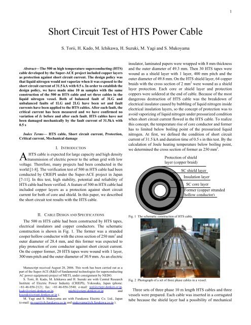
Protection <strong>of</strong> shield<br />
layer (copper braid)<br />
Fig. 1 The schematic construction <strong>of</strong> <strong>HTS</strong> cable.<br />
SC shield layer<br />
Insulation layer<br />
SC core layer<br />
Former (copper stranded<br />
hollow conductor)<br />
Fig. 2 Photograph <strong>of</strong> a set <strong>of</strong> three phase cables in a vessel.<br />
Three sets <strong>of</strong> three phase 10 m length <strong>HTS</strong> cables and three<br />
vessels were prepared. Each cable was inserted in a corrugated<br />
tube because the shield layer had a possibility <strong>of</strong> mechanical<br />
1
Critical current, Ic, <strong>of</strong> each cable both <strong>of</strong> core conductors and<br />
shield layers are listed in Table I. The criterion <strong>of</strong> Ic is 1 µV/cm<br />
in the core conductor and shield layer.<br />
A. 3LG short circuit current tests<br />
3LG short circuit tests <strong>of</strong> 10 kA, 20 kA and 315 kA were<br />
conducted with “north”, “south” and “center”, respectively.<br />
These test results are listed in Table II, and a current wave<br />
forms <strong>of</strong> 3LG, 31.5 kA and 0.52 s is shown in Fig. 6.<br />
<strong>Cable</strong><br />
Voltage<br />
(kV)<br />
North 8.24<br />
South 8.26<br />
Center 8.26<br />
Phase<br />
TABLE II<br />
TEST RESULTS OF 3LG.<br />
Peak<br />
value <strong>of</strong><br />
first<br />
wave<br />
(kApeak)<br />
RMS<br />
value<br />
after 3<br />
cycles<br />
(kArms)<br />
Measured Ic after test<br />
Core (A)<br />
Shield<br />
(A)<br />
R 28.5 10.2 1,320 2,010<br />
S 22.0 10.2 1,220 1,920<br />
T 21.1 10.2 1,080 1,780<br />
R 57.1 20.0 1,470 2,260<br />
S 43.5 20.2 1,410 2,110<br />
T 43.3 20.1 1,320 2,010<br />
R 90.2 31.2 1,480 2,270<br />
S 64.4 31.7 1.520 2,350<br />
T 73.4 31.4 1,570 2,200<br />
Fig. 6 The current wave forms <strong>of</strong> 3LG, 31.5 kA, 0.5 s short circuit.<br />
From the test result, phases R and T were injected large DC<br />
component and reduced about 0.2 s. From the signals <strong>of</strong><br />
Rogowski coils, it was cleared that short circuit current mainly<br />
flowed in protection copper conductor both <strong>of</strong> core and shield.<br />
Critical currents <strong>of</strong> these core and shield layer did not vary after<br />
short circuit tests. Also, the <strong>HTS</strong> cable was not injured<br />
mechanical damage against 3LG short circuit test.<br />
B. Unbalanced short circuit test results (1LG and 2LG)<br />
Unbalanced short circuit current tests both <strong>of</strong> 2LG and 1LG<br />
were conducted by “center” set. The test results <strong>of</strong> 2LG and<br />
1LG are listed in Table III and Table IV, respectively. Current<br />
wave forms <strong>of</strong> 31.5 kA both <strong>of</strong> 2LG and 1LG are shown in Fig.<br />
7 and 8, respectively.<br />
<strong>Cable</strong><br />
Voltage<br />
(kV)<br />
Center 12<br />
Center 12<br />
Center 11.6<br />
Phase<br />
TABLE III<br />
TEST RESULTS OF 2LG.<br />
Peak<br />
value <strong>of</strong><br />
first<br />
wave<br />
(kApeak)<br />
RMS<br />
value<br />
after 3<br />
cycles<br />
(kArms)<br />
Measured Ic after test<br />
Core (A)<br />
Shield<br />
(A)<br />
R 27.8 9.88 1,500 2,260<br />
S 15.0 10.1 1,550 2,350<br />
T 0.83 0.56 - -<br />
R 51.4 18.3 1,480 2,260<br />
S 30.7 18.4 1,540 2.350<br />
T 1.29 0.85 - -<br />
R 92.3 32.3 1,480 2,270<br />
S 64.1 32.6 1,520 2,340<br />
T 1.25 0.81 - -<br />
Fig. 7 Current wave forms <strong>of</strong> 2LG, 31.5 kA, 0.5 s short circuit.<br />
<strong>Cable</strong><br />
Voltage<br />
(kV)<br />
Center 12<br />
Center 12<br />
Center 16.9<br />
Phase<br />
TABLE IV<br />
TEST RESULTS OF 1LG.<br />
Peak<br />
value <strong>of</strong><br />
first<br />
wave<br />
(kApeak)<br />
RMS<br />
value<br />
after 3<br />
cycles<br />
(kArms)<br />
Measured Ic after test<br />
Core (A)<br />
Shield<br />
(A)<br />
R 27.4 10.2 1,480 2,260<br />
S 1.25 0.87 - -<br />
T 1.25 0.85 - -<br />
R 53.3 19.8 1,470 2,260<br />
S 1.30 0.90 - -<br />
T 1.30 0.88 - -<br />
R 83.6 31.4 1,480 2,270<br />
S 1.30 0.90 - -<br />
T 1.29 0.88 - -<br />
3