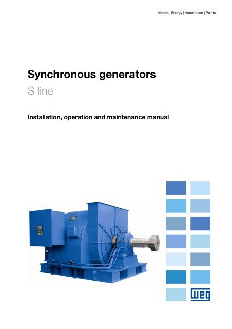
Synchronous generator S line - Weg
Synchronous generator S line - Weg
Synchronous generator S line - Weg

Create successful ePaper yourself
Turn your PDF publications into a flip-book with our unique Google optimized e-Paper software.
<strong>Synchronous</strong> <strong>generator</strong>s<br />
S <strong>line</strong><br />
Installation, operation and maintenance manual<br />
Motors | Energy | Automation | Paints
S LINE GENERATORS<br />
2<br />
FOREWORD<br />
The electricity plays an important role on people’s life either supporting<br />
them on the achievement of new developments and progress<br />
or providing them comfort and entertainment.<br />
The <strong>generator</strong> is the equipment used to generate such<br />
energy through different means such as aeolic,<br />
hydraulic, thermal systems and others.<br />
Considering the prominent role the <strong>generator</strong> plays,<br />
it should be regarded as a prime power unit.<br />
This means to say that both its installation and maintenance<br />
require special care in order to ensure perfect operation and longer life to the unit.<br />
THE INSTALLATION AND MAINTENANCE MANUAL FOR S LINE GENERATORS<br />
intends to assist those who deal with electric machines making<br />
their tasks easier to preserve an important equipment:<br />
THE GENERATOR.<br />
WEG EQUIPAMENTOS ELÉTRICOS S.A. - MÁQUINAS<br />
---- IMPORTANT ----<br />
READ CAREFULLY THE INSTRUCTIONS INCLUDED IN THIS MANUAL IN<br />
ORDER TO ENSURE A SAFE AND CONTINUOUS OPERATION TO THE<br />
EQUIPMENT.<br />
9300.0018 I/3<br />
Material: 10040213<br />
February 2008
S LINE GENERATORS<br />
TABLE OF CONTENTS<br />
1. NOMENCLATURE ........................................................................................................................ 6<br />
2. INTRODUCTION ......................................................................................................................... 7<br />
3. GENERAL INSTRUCTIONS .......................................................................................................... 7<br />
3.1. SAFETY INSTRUCTIONS ........................................................................................................7<br />
3.2. UNPACKING..........................................................................................................................7<br />
3.3. STORAGE .............................................................................................................................7<br />
3.3.1. BEARINGS.................................................................................................................................. 8<br />
3.3.2. SLEEVE BEARINGS .................................................................................................................... 8<br />
3.4. PROLONGED STORAGE..........................................................................................................9<br />
3.4.1. INTRODUCTION ......................................................................................................................... 9<br />
3.4.2. GENERALITIES........................................................................................................................... 9<br />
3.4.3. STORAGE PLACE ........................................................................................................................ 9<br />
3.4.3.1. INTERNAL STORAGE ..................................................................................................... 9<br />
3.4.3.2. EXTERNAL STORAGE................................................................................................... 10<br />
3.4.5. SPARE PARTS........................................................................................................................... 10<br />
3.4.6. SPACE HEATER ........................................................................................................................ 10<br />
3.4.7. INSULATION RESISTANCE ........................................................................................................ 10<br />
3.4.8. EXPOSED MACHINED SURFACES............................................................................................... 10<br />
3.4.9. BEARINGS................................................................................................................................ 11<br />
3.4.9.1. ANTIFRICTION BEARING LUBRICATED BY GREASE....................................................... 11<br />
3.4.9.2. ANTIFRICTION BEARING LUBRICATED BY OIL ............................................................. 11<br />
3.4.9.3. SLEEVE BEARING........................................................................................................ 11<br />
3.4.10. BRUSHES ............................................................................................................................... 11<br />
3.4.11. CONNECTION BOX: ................................................................................................................ 12<br />
3.4.12. PREPARATION FOR SERVICE AFTER LONG TERM STORAGE...................................................... 12<br />
3.4.12.1. CLEANING ................................................................................................................ 12<br />
3.4.12.2. BEARINGS LUBRICATION .......................................................................................... 12<br />
3.4.12.3. ISOLATION RESISTANCE VERIFICATION .................................................................... 12<br />
3.4.12.4. OTHER ..................................................................................................................... 12<br />
3.4.13. MAINTENANCE PLAN FOR STORAGE........................................................................................ 13<br />
3.5. INSULATION RESISTANCE ...................................................................................................14<br />
3.6. HANDLING ......................................................................................................................... 15<br />
4. GENERAL ASPECTS OF THE MAIN MACHINE............................................................................16<br />
4.1. STATOR OF THE MAIN MACHINE .........................................................................................16<br />
4.1.1. ROTOR OF THE MAIN MACHINE................................................................................................ 16<br />
4.2. MAIN EXCITER.................................................................................................................... 16<br />
4.2.1. STATOR OF THE MAIN EXCITER................................................................................................ 16<br />
4.2.2. ROTOR OF THE MAIN EXCITER................................................................................................. 16<br />
4.2.3. AUXILIARY WINDING ............................................................................................................... 16<br />
4.2.4. SLIP RINGS.............................................................................................................................. 17<br />
4.2.5. BRUSH HOLDERS ..................................................................................................................... 17<br />
4.2.6. BRUSHES................................................................................................................................. 18<br />
4.3. EXCITATION AND DISEXCITATION.......................................................................................19<br />
3
S LINE GENERATORS<br />
4.4. VOLTAGE REGULATOR ........................................................................................................19<br />
4.5. SUBFREQUENCY PROTECTION.............................................................................................19<br />
4.6. ADJUSTING POTENTIOMETER OF THE THEORETICAL VALUE .................................................19<br />
4.7. STATIC EXCITER (SLIP RING GENERATORS).........................................................................19<br />
5. INSTALLATION.........................................................................................................................20<br />
5.1. ROTATION DIRECTION .......................................................................................................20<br />
5.2. MECHANICAL ASPECTS........................................................................................................20<br />
5.2.1. FOUNDATIONS......................................................................................................................... 20<br />
5.2.1.1. METALLIC BASES ........................................................................................................ 20<br />
5.2.2. ALIGNMENT/LEVELING ............................................................................................................. 20<br />
5.2.3. DIRECT COUPLING................................................................................................................... 21<br />
5.2.4. COUPLING ARRANGEMENT FOR SLEEVE BEARING GENERATORS – AXIAL CLEARANCE ................ 21<br />
5.3. ELECTRICAL ASPECTS ......................................................................................................... 23<br />
5.3.1. PROTECTIONS ......................................................................................................................... 23<br />
5.3.1.1. GENERATOR ............................................................................................................... 23<br />
5.3.1.2. TEMPERATURE LIMITS FOR WINDINGS ....................................................................... 23<br />
5.3.1.3. IN THE PANEL ............................................................................................................ 24<br />
5.3.2. SPACE HEATERS....................................................................................................................... 25<br />
5.3.3. VIBRATION LIMITS .................................................................................................................. 25<br />
5.3.4. SHAFT VIBRATION LIMITS........................................................................................................ 25<br />
5.4. COMMISSIONING................................................................................................................ 26<br />
5.4.1. PRELIMINARY INSPECTION ...................................................................................................... 26<br />
5.4.2. START-UP ................................................................................................................................ 26<br />
5.4.3. OPERATION ............................................................................................................................. 26<br />
5.4.4. PARALLEL OPERATION ............................................................................................................. 26<br />
5.4.5. SWITCHING OFF ...................................................................................................................... 26<br />
6. MAINTENANCE .........................................................................................................................27<br />
6.1. CONNECTION DIAGRAMS ....................................................................................................27<br />
6.2. COMPLETE MAINTENANCE..................................................................................................28<br />
6.3. RADIATOR - AIR COOLER WITH ENCLOSED CIRCUIT ............................................................29<br />
6.3.1. GENERAL ASPECTS................................................................................................................... 29<br />
6.3.2. COMMISSIONING ..................................................................................................................... 29<br />
6.3.3. MAINTENANCE (RADIATOR) ..................................................................................................... 29<br />
6.3.4. CLEANLINESS (RADIATOR) ....................................................................................................... 29<br />
7. LUBRICATION ..........................................................................................................................30<br />
7.1. GREASE LUBRICATED BEARINGS .........................................................................................30<br />
7.1.1. LUBRICATION INTERVALS ........................................................................................................ 30<br />
7.1.2. QUALITY AND QUANTITY OF GREASE ....................................................................................... 30<br />
7.1.3. GREASE COMPATIBILITY .......................................................................................................... 30<br />
7.1.4. LUBRICATION INSTRUCTIONS.................................................................................................. 31<br />
7.1.5. REPLACEMENT OF BEARINGS ................................................................................................... 31<br />
7.1.6. SLEEVE BEARINGS ................................................................................................................... 32<br />
7.1.6.1. GENERAL INSTRUCTIONS............................................................................................ 32<br />
7.1.6.2. DISASSEMBLY OF SLEEVE BEARING (TYPE "EF / EM = B3", “ER / EG = D5 / D6”).......... 32<br />
7.1.6.3. SLEEVE BEARING ASSEMBLY ....................................................................................... 33<br />
7.1.6.4. SETTING OF THERMAL PROTECTIONS (100) ................................................................ 37<br />
7.1.6.5. WATER COOLING METHODS ....................................................................................... 37<br />
4
S LINE GENERATORS<br />
7.1.6.6. LUBRICATION............................................................................................................. 37<br />
7.1.6.7. SHAFT SEALS.............................................................................................................. 37<br />
7.1.6.8. OPERATION................................................................................................................ 37<br />
7.2. AIR GAP CHECKING ............................................................................................................ 38<br />
7.3. DRYING OF THE WINDING ..................................................................................................38<br />
8. REPLACEMENT OF ROTATING DIODES ....................................................................................39<br />
9. MAINTENANCE SCHEDULE .......................................................................................................52<br />
10. ABNORMAL SITUATIONS DURING OPERATION ....................................................................53<br />
WARRANTY TERMS FOR ENGINEERING PRODUCTS ...................................................................55<br />
5
1. NOMENCLATURE<br />
GENERATOR LINE<br />
S – S Line<br />
S LINE GENERATORS<br />
EXCITATION CHARACTERISTICS<br />
T - Brushless with auxiliary coil<br />
P - Brushless with auxiliary exciter<br />
S - Brushless without auxiliary coil (exciter)<br />
L - Generator with brushes<br />
COOLING SYSTEM<br />
A – Open self-ventilated<br />
F – Self ventilated with air-to-air heat exchanger on top of motor<br />
W – Air-to-water heat exchanger<br />
I – Independent forced ventilation with air-to-air heat exchanger<br />
D – Self-ventilated, air inlet and outlet by ducts<br />
T – Independent forced ventilation, air inlet and outlet by ducts<br />
L – Independent forced ventilation with Air-to-water exchanger<br />
V – Independent forced ventilation over the motor - opened<br />
IEC FRAME<br />
Shaft-end height in mm (450 up to 5000)<br />
6<br />
S P W 1250
2. INTRODUCTION<br />
IMPORTANTE:<br />
All standards and procedures<br />
included in this manual must be<br />
followed accordingly to ensure a<br />
proper operation to the equipment as well as to<br />
ensure safety conditions to the personnel involved<br />
in the <strong>generator</strong> operation. Following these<br />
instructions is also important for the warranty as<br />
explained at the end of this manual.<br />
Therefore, we strongly recommend to read this<br />
manual carefully before <strong>generator</strong> installation and<br />
operation. In case of any further doubt, please<br />
contact <strong>Weg</strong> Máquinas.<br />
3. GENERAL INSTRUCTIONS<br />
3.1. SAFETY INSTRUCTIONS<br />
All personnel involved with electrical installations,<br />
either handling, lifting, operation and<br />
maintenance, should be well-informed and<br />
updated concerning safety standards and<br />
principles the govern the work. Before work<br />
commences, it is the responsibility of the person<br />
in charge to ascertain that these have been duly<br />
complied with and alert his personnel of the<br />
inherent hazards of the job in hand.<br />
When incorrectly installed and improperly used or<br />
in cases of poor maintenance, these <strong>generator</strong>s<br />
can cause either injury to people and/or material<br />
damage.<br />
So it is recommended that these tasks be<br />
undertaken by qualified personnel who has<br />
received adequate training, experience,<br />
professional instruction, knowledge of technical<br />
standards, specifications and safety standards,<br />
knowledge about accident prevention and<br />
operation conditions. Equipment for fire<br />
extinguishing and notice of first aid should be<br />
placed at accessible and visible locations.<br />
S LINE GENERATORS<br />
7<br />
3.2. UNPACKING<br />
Prior to shipment, all <strong>generator</strong>s are factorytested<br />
and supplied in perfect operating<br />
conditions. All adjusting and machining surfaces<br />
are duly protected with corrosion inhibitors. Upon<br />
receipt, we recommend to check the boxes to<br />
see if any damage has occurred during<br />
transportation.<br />
If any, contact the carrier, insurance company<br />
and <strong>Weg</strong> Máquinas.<br />
The lack of notice will void the warranty.<br />
When lifting the boxes (or container) it is<br />
important to pay attention to the areas<br />
appropriated for this purposes well as to check<br />
weight of the box along with hoist capacity.<br />
Those <strong>generator</strong>s shipped in wooden boxes can<br />
only be lifted by the eyebolts or using forklift<br />
machines and never lifted by the shaft or box.<br />
The box should never be turned around. Lifting<br />
and lowering of such boxes must be done gently<br />
in order to avoid damage to the bearings.<br />
Make a visual inspection after the unpacking has<br />
been done. Do not remove the protecting grease<br />
from the shaft end neither the stoppers from the<br />
terminal boxes. These protection devices should<br />
remain in place until the installation is finished.<br />
For <strong>generator</strong>s fitted with shaft locking device,<br />
this device must be removed, and the rotor<br />
rotated several times by hands. If damages are<br />
noticed, contact the carrier and <strong>Weg</strong> Máquinas.<br />
3.3. STORAGE<br />
When <strong>generator</strong>s are not immediately unpacked,<br />
boxes should be stored in their normal upright<br />
position in a dry temperature room, free of dust,<br />
dirt, gases, insects and corrosive atmosphere.<br />
Generators must be stored in places free of<br />
vibrations in order to avoid bearing damage. For<br />
<strong>generator</strong>s fitted with space heaters, these<br />
accessories must be kept switched-on. If painting<br />
has suffered any damage, it must be repainted to<br />
avoid rust. The same applies to machined<br />
surfaces when protecting grease has been<br />
wasted.
3.3.1. BEARINGS<br />
When <strong>generator</strong> is kept in stock for a period of six<br />
months or less, it is not require to effect a full<br />
inspection on the bearings before running it. What<br />
has to be done is to rotate manually the shaft<br />
monthly.<br />
However, when <strong>generator</strong> is kept in stock for<br />
more than six months, bearings must be<br />
regreased, before operation. On the other hand, if<br />
the <strong>generator</strong> is kept in stock for approximately 2<br />
year or more, bearings must be disassembled and<br />
washed and checked. After the reassembly,<br />
bearings must be regreased. Generators fitted<br />
with shielded bearings must have these bearings<br />
replaced when <strong>generator</strong>s are kept in stock for a<br />
period exceeding 2 years.<br />
3.3.2. SLEEVE BEARINGS<br />
Sleeve bearing performance depends on adequate<br />
installation, lubrication and maintenance. Before<br />
assembling or disassembling the bearing, carefully<br />
read the instructions contained herein.<br />
The procedures described on item 7.1.6.2 and<br />
7.1.6.3 refers to assembly and disassembly of<br />
bearings used in electric machines with the rotor<br />
already mounted.<br />
S LINE GENERATORS<br />
8
3.4. PROLONGED STORAGE<br />
3.4.1. INTRODUCTION<br />
The instructions for long term storage described<br />
as follow are valid for <strong>generator</strong>s to be long<br />
term stored and/or long periods of standstill<br />
before the commissioning.<br />
3.4.2. GENERALITIES<br />
The existing tendency, especially during the<br />
construction of the plant, of storing the<br />
<strong>generator</strong>s for several years before<br />
commissioning or to install immediately some<br />
units, results that the <strong>generator</strong>s are exposed to<br />
influences that cannot be evaluated in advance<br />
for this time's period.<br />
It is difficult to evaluate the different forms of<br />
stress (atmospheric, chemical, thermal, and<br />
mechanic) imposed to the <strong>generator</strong>, which<br />
might happen during storage maneuvers,<br />
assembly, initial tests and storage until the<br />
commissioning.<br />
Other essential factor is the transportation, for<br />
example, the general contractor may transport<br />
the <strong>generator</strong> or the complete unit with<br />
<strong>generator</strong> as joint transportation to the<br />
installation location.<br />
The <strong>generator</strong> internal gaps (air gap, bearings<br />
and interior of connection box) are exposed to<br />
the atmospheric air and temperature<br />
fluctuations. Due to the air humidity, it is<br />
possible the liquid condensation and, depending<br />
on the kind and air contamination degree,<br />
aggressive substances may penetrate into these<br />
spaces.<br />
As a consequence after long periods, the<br />
internal components such as the bearings might<br />
get rust, the insulation resistance can decrease<br />
to under the admissible values and the grease<br />
lubricant capacity in the bearings is adversely<br />
affected. This influence increases the damage<br />
risk before commissioning of the plant.<br />
To keep manufacturer's warranty, should<br />
be insured that the described preventive<br />
measures in this instructions, as:<br />
constructive aspects, preservation,<br />
packing, storage and inspections, be<br />
followed and registered.<br />
S LINE GENERATORS<br />
9<br />
3.4.3. STORAGE PLACE<br />
In order to provide the best storage conditions<br />
to the <strong>generator</strong> during long standstill periods,<br />
the storage location should obey rigorously the<br />
criteria described as follow:<br />
3.4.3.1. INTERNAL STORAGE<br />
- Closed storage room with roof;<br />
- The location must be protected against<br />
humidity, vapors, aggressive fumes discharge,<br />
fast heat changes, gnawing and insects.<br />
- It must not present corrosive gases such as<br />
chlorine, sulfur dioxide or acid;<br />
- It must not present continuous or<br />
intermittent severe vibrations.<br />
- To have ventilation system with filter;<br />
- It must not present quickly changes of<br />
temperature;<br />
- Ambient temperature (5° C, > t < 60 °C)<br />
and must not present quickly changes of<br />
temperature;<br />
- Relative air humidity < 50%;<br />
- To have prevention against dirt and dust<br />
deposits;<br />
- To have fire detection system.<br />
- Electrical supply for space heater and<br />
illumination must be provided;<br />
If some of these requisites do not be attended<br />
by the storage environment, WEG suggests that<br />
additional protections be incorporated in the<br />
<strong>generator</strong> packing during the storage period, like<br />
follows:<br />
- Closed wooden or similar box with electrical<br />
installation, enable to the space heaters<br />
supply;<br />
- Closed wooden box or similar with<br />
installation that allows the space heaters be<br />
energized;<br />
- If there is a risk of fungus infestation and<br />
formation, the packing must be protected in<br />
the storage location by spraying or painting it<br />
with appropriated chemical agents.<br />
- Preparation of packing must be done with<br />
greatest care by an experienced person. A<br />
reliable packing company must take over of<br />
the packing.
3.4.3.2. EXTERNAL STORAGE<br />
The outdoor storage of the <strong>generator</strong> is<br />
not recommended.<br />
If the external storage cannot be avoided, the<br />
<strong>generator</strong> should be packed in specific packing<br />
for this condition, as described bellow.<br />
- For outdoor storage, besides the packing<br />
recommended above, we recommend to cover<br />
completely this packing with a protection<br />
against dust, humidity and other strange<br />
materials.<br />
- Place the packing in pallets, wooden<br />
bunches or foundations that guarantee the<br />
protection against the soil humidity.<br />
- Prevent the packing sink itself in the soil.<br />
- After covering the machine, a shed should<br />
be build to protect it of rain, snow and<br />
excessive sun heat.<br />
IMPORTANT<br />
It is recommendable check the storage local<br />
conditions and the <strong>generator</strong>s condition<br />
according to the maintenance plan for long term<br />
storage, described in this manual.<br />
3.4.5. SPARE PARTS<br />
- If parts have been supplied separately<br />
(connection boxes, heat exchanger, covers,<br />
etc...) these parts must be packed as<br />
described above.<br />
- The air relative humidity inside the packing<br />
should not exceed 50% until unpacking the<br />
machine.<br />
3.4.6. SPACE HEATER<br />
- The space heater installed in the <strong>generator</strong><br />
must be energized during the storage period<br />
to avoid the moisture condensation inside the<br />
<strong>generator</strong> and this way keeping the winding<br />
insulation resistance within acceptable levels.<br />
THE SPACE HEATER OF THE GENERATOR MUST<br />
BE MANDATORILY ENERGIZED WHEN THE<br />
GENERATOR IS STORED IN LOCAL WITH<br />
TEMPERATURE < 5 °C AND RELATIVE AIR<br />
HUMIDITY > 50%.<br />
S LINE GENERATORS<br />
10<br />
3.4.7. INSULATION RESISTANCE<br />
- During the storage period, the winding<br />
insulation resistance of the <strong>generator</strong> should<br />
be measured according to item 2.3.5 of this<br />
manual and registered every 3 months and<br />
before the <strong>generator</strong> installation.<br />
- Eventual drops in the insulation resistance<br />
level must be investigated.<br />
3.4.8. EXPOSED MACHINED SURFACES<br />
- At factory, all exposed surfaces (for<br />
example, the shaft edge and flanges) are<br />
protected with a temporary protective agent<br />
(rust inhibiter).<br />
- This protective coating should be reapplied<br />
every 6 months at least. When this coating is<br />
removed and/or damaged, the same<br />
preventive action must be done.<br />
Recommended products:<br />
Name: Dasco Guard 400 TX AZ, Manufacturer:<br />
D.A. Stuart Ltda.<br />
Name: TARP, Manufacturer: Castrol.
3.4.9. BEARINGS<br />
3.4.9.1. ANTIFRICTION BEARING<br />
LUBRICATED BY GREASE<br />
The bearings are lubricated in the factory for<br />
make the <strong>generator</strong> tests.<br />
During the storage period, every two months is<br />
necessary to remove the shaft brake device and<br />
turn the shaft manually to conserve the bearing in<br />
good conditions.<br />
After 6 months of storage and before starting in<br />
operation, the bearings should be regreased, as<br />
item 4.2.1.5 of this manual.<br />
If <strong>generator</strong> is kept in storage for approximately 2<br />
years or more, the bearings must be inspected<br />
and regreased according to item 4.2 of this<br />
manual.<br />
3.4.9.2. ANTIFRICTION BEARING<br />
LUBRICATED BY OIL<br />
- Depending on the position, the <strong>generator</strong> can<br />
be transported with or without oil in your<br />
bearings.<br />
- The <strong>generator</strong> must be stored in its original<br />
position of operation and with oil in the<br />
bearings;<br />
- The oil level should be respected, remaining in<br />
the half the oil sight glass.<br />
During the storage period, every two months is<br />
necessary to remove the shaft brake device and<br />
turn the shaft manually to conserve the bearing in<br />
good conditions.<br />
After 6 months of storage and before starting in<br />
operation, the bearings should be relubricated, as<br />
item 4.2.3.1 of this manual.<br />
If <strong>generator</strong> is kept in storage for approximately 2<br />
years or more, the bearings must be inspected<br />
and relubricated according to item 4.2 of this<br />
manual.<br />
3.4.9.3. SLEEVE BEARING<br />
- Depending on the position, the <strong>generator</strong> can<br />
be transported with or without oil in your<br />
bearings;<br />
- The <strong>generator</strong> must be stored in its original<br />
position of operation and with oil in the<br />
bearings;<br />
- The oil level should be respected, remaining in<br />
the half the oil sight glass;<br />
- During the storage period, every two months is<br />
necessary to remove the shaft brake device<br />
and rotate at about 30 rpm for the oil<br />
circulation and to conserve the bearing in good<br />
conditions.<br />
S LINE GENERATORS<br />
11<br />
If is not possible to rotate the shaft of the<br />
<strong>generator</strong>, the follow procedure should be used to<br />
protect internally the bearing and the contact<br />
surfaces against corrosion:<br />
- Drain the whole bearing oil;<br />
- Dismantle the bearing, following the procedure<br />
described in the item 4.2.4.2 of this manual;<br />
- Clean the bearing;<br />
- Apply the anti-corrosive (ex.: TECTIL 511,<br />
Valvo<strong>line</strong> or Dasco Guard 400TXAZ) in the<br />
bearing, bearing <strong>line</strong> (top and bottom half)<br />
and in the shaft contact surface of the<br />
<strong>generator</strong>;<br />
- Assemble the bearing, following the procedure<br />
described in the item 4.2.4.3 of this manual;<br />
- Close all tapped holes with screw plugs;<br />
- Seal the gaps between the shaft and bearing<br />
seal and between bearing seal and bearing<br />
housing by using self-adhesive permanent<br />
tape;<br />
- Connecting flanges (Ex.: Oil inlet and outlet)<br />
must be covered with blank plates.<br />
- Remove the bearing top sight glass and spray<br />
the corrosion inhibitor on the bearing.<br />
- Put some desiccant (silica gel) inside of the<br />
bearing. The desiccant absorbs the humidity<br />
and prevents the formation of moisture and<br />
water condensation inside the bearing.<br />
- Close the bearing tightly with the top sight<br />
glass.<br />
In case the standstill period is longer then 6<br />
months:<br />
- Repeat the procedures described above.<br />
- Replace the desiccant (silica gel) into the<br />
bearing each six months.<br />
In case the standstill period is longer than 2<br />
years:<br />
- Dismantle the bearing;<br />
- Preserve and store the bearing parts.<br />
3.4.10. BRUSHES<br />
- The brushes (if any) of the <strong>generator</strong>s should<br />
be lifted in the brush-holder, because should<br />
not remain in contact with the slip-rings during<br />
the storage period, avoiding thus the slip-rings<br />
oxidation.<br />
- Before the <strong>generator</strong> installation and<br />
commissioning, the brushes should come back<br />
to the original position.
3.4.11. CONNECTION BOX:<br />
When the winding insulation resistance of the<br />
<strong>generator</strong> is verified, the terminal box and<br />
accessories box must also be verified:<br />
- The interior should be dry, cleaned and free of<br />
any dust deposit.<br />
- The contacts should be free of rust<br />
(corrosion).<br />
- The seals should be in good conditions.<br />
- The cables inlet should be correctly sealed.<br />
If any of these items is not correct, the parts<br />
must be cleaned or replaced.<br />
3.4.12. PREPARATION FOR SERVICE AFTER<br />
LONG TERM STORAGE<br />
3.4.12.1. CLEANING<br />
- The machine interior and exterior should be<br />
free of oil, water, dust and dirt. The inside of<br />
the <strong>generator</strong> should be vacuum cleaned.<br />
- Remove the corrosion inhibitor of the exposed<br />
surfaces with a cloth soaked in petroleum<br />
based solvent.<br />
- Be sure that the bearings and cavities used to<br />
lubrication are free of dirt and the plugs on the<br />
holes are correctly sealed and tighten.<br />
Oxidations and marks on the bearings seats<br />
and shaft should be carefully removed.<br />
3.4.12.2. BEARINGS LUBRICATION<br />
Use grease or oil specified for bearings<br />
lubrication. This information is printed on the<br />
bearings nameplate and the lubrication should be<br />
made as described in the chapter 4 “Maintenance”<br />
of this Manual, according to the bearing type.<br />
Note: Sleeve bearings, where was applied<br />
internally the protection product against corrosion<br />
and desiccant, these bearings should be<br />
dismounted as the procedure described in the<br />
item 7.1.6.2 of this manual, washes for remove<br />
the anti-corrosive and the desiccants must be<br />
removed.<br />
Assemble again the bearings, as the procedure<br />
described in the item 7.1.6.3 of this manual and<br />
proceeds the re-lubrication.<br />
S LINE GENERATORS<br />
12<br />
3.4.12.3. ISOLATION RESISTANCE<br />
VERIFICATION<br />
Before starting in operation the insulation<br />
resistance must be verified, according to the item<br />
3.5 of this manual.<br />
3.4.12.4. OTHER<br />
Follow the further procedures described in the<br />
chapter 5.4 “Commissioning” of this manual,<br />
before putting the machine in operation.
3.4.13. MAINTENANCE PLAN FOR STORAGE<br />
S LINE GENERATORS<br />
During the storage period, the <strong>generator</strong> maintenance must be executed and registered according to the<br />
plan described in the table below:<br />
Monthly<br />
Each two<br />
months<br />
13<br />
Each six<br />
months<br />
Each 2<br />
years<br />
Before<br />
operation<br />
Storage local<br />
Inspect the cleaning conditions X X<br />
Inspect the humidity and temperature<br />
conditions<br />
X<br />
Verify signals insects infestations X<br />
Measure the vibration level<br />
Packing<br />
X<br />
Inspect physical damages X<br />
Inspect the relative humidity in the<br />
interior<br />
X<br />
Change desiccant in the packing<br />
(if any)<br />
Space heater<br />
X When necessary<br />
Verify the operation conditions<br />
Complete <strong>generator</strong><br />
X<br />
Make external cleaning X X<br />
Verify the painting conditions X<br />
Verify the rust inhibitor in the exposed<br />
parts<br />
X<br />
Replace the rust inhibitor<br />
Windings<br />
X<br />
Measure the insulation resistance X X<br />
Measure the polarization index<br />
Connection box and grounding terminals<br />
X X<br />
Clean the inside of the box<br />
Inspect the seals and gaskets<br />
X X<br />
Antifriction bearing lubricated by grease or oil<br />
Turn the shaft X<br />
Relubricate the bearing X X<br />
Dismount and clean the bearing<br />
Sleeve bearing<br />
X<br />
Turn the shaft X<br />
Apply rust inhibitor and desiccant X<br />
Clean and relubricate the bearings X<br />
Dismount and store the parts<br />
Brushes (if any)<br />
X<br />
Lift the brushes During the storage<br />
Lower the brushes and verify the<br />
contact with the slip-rings<br />
X<br />
Note
3.5. INSULATION RESISTANCE<br />
When <strong>generator</strong> is not immediately put into<br />
operation, it should be protected against<br />
moisture, high temperatures and impurities in<br />
order to avoid damage to the insulation. The<br />
winding insulation resistance must be measured<br />
before operating the <strong>generator</strong>.<br />
If the environment contains high humidity, a<br />
periodical inspection is recommended during<br />
storage. It is difficult to determine rules for the<br />
actual insulation resistance value for <strong>generator</strong>s<br />
as the resistance varies according to<br />
environmental conditions (dust, oil, grease, dirt)<br />
and condition of the insulating material used and<br />
manufacturing process of the <strong>generator</strong>. A lot of<br />
experience is required to decide when a <strong>generator</strong><br />
is ready for operation. Periodical records will help<br />
to take such decision.<br />
The following guide<strong>line</strong>s show the approximate<br />
insulation resistance values that can be expected<br />
from a clean and dry <strong>generator</strong> at 40°C<br />
temperature ambient, when test voltage is applied<br />
for a period of one minute supplied by the curve<br />
of figure 1, as per NBR 5383 Standard.<br />
The RM insulation resistance is given by the<br />
formula:<br />
Rm = Un + 1<br />
Where:<br />
RM – Minimum insulation resistance<br />
recommended in Mega Ohm with the winding at<br />
a temperature of 40ºC.<br />
Un – Rated voltage of the <strong>generator</strong> in kV.<br />
If the test is performed at a different<br />
temperature, it is necessary to correct the reading<br />
to 40°C using an insulation resistance variation<br />
curve in relation to temperature, given by the<br />
<strong>generator</strong> itself. If this curve is not available, it is<br />
possible to use an approximate correction given<br />
by the curve of figure 1, as per NBR 5383<br />
Standard.<br />
On new <strong>generator</strong>s, lower values are sometimes<br />
obtained as solvents are present in the insulating<br />
varnishes which become volatile in a later stage<br />
during normal operation. This does not<br />
necessarily mean that the <strong>generator</strong> is not<br />
suitable for operation once the insulation<br />
resistance will increase after a certain period of<br />
operation.<br />
On old <strong>generator</strong>s, still in operation, higher values<br />
are usually obtained. The comparison with values<br />
obtained from previous tests on the same<br />
<strong>generator</strong>s under identical load, temperature and<br />
humidity conditions will be a better indication of<br />
the insulation conditions in comparison to the<br />
value obtained from a single test. Any sudden or<br />
S LINE GENERATORS<br />
14<br />
high reduction of the value requires careful<br />
attention.<br />
The insulation resistance is normally measured<br />
with a Mega-ohmmeter.<br />
If the insulation resistance value is lower than the<br />
values obtained through the above mentioned<br />
formula, <strong>generator</strong> must be submitted to a drying<br />
process according to item 5.7.<br />
Insulation resistance<br />
value<br />
Insulation level<br />
2MΩ or lower Bad<br />
< 50MΩ Dangerous<br />
50...100MΩ Regular<br />
100...500MΩ Good<br />
500...1000MΩ Very Good<br />
> 1000MΩ Excellent<br />
Table 2.1. - Guide limits for insulation resistance of<br />
electrical machines.<br />
Polarization Index Insulation Level<br />
1 or lower Bad<br />
< 1.5 Dangerous<br />
1.5 to 2.0 Regular<br />
2.0 to 3.0 Good<br />
3.0 to 4.0 Very good<br />
> 4.0 Excellent<br />
Table 2.2. - Polarization Index (ratio between 1 and 10<br />
minutes).
Figure 1.<br />
S LINE GENERATORS<br />
15<br />
3.6. HANDLING<br />
Use only the existing eyebolts to lift the<br />
<strong>generator</strong>. Never lift the <strong>generator</strong> by the shaft.<br />
Check the <strong>generator</strong> weight. Lifting and lowering<br />
must be done gently in order to avoid damage to<br />
the bearings. The eyebolts attached to bearing<br />
housing, heat exchanger, endbells, etc, should be<br />
used to handle these components only.
4. GENERAL ASPECTS OF THE MAIN<br />
MACHINE<br />
The WEG S Line Generators (Brushless) are<br />
composed of:<br />
a) Main machine.<br />
b) Main exciter.<br />
c) Static voltage regulator.<br />
Machine with brushes:<br />
a) Main machine.<br />
b) Slip rings.<br />
4.1. STATOR OF THE MAIN MACHINE<br />
The frame is isolated and made of calendered<br />
steel plates. The stator core with its<br />
corresponding winding is fitted inside the<br />
<strong>generator</strong> frame.<br />
Low voltage windings are produced for class H<br />
insulation. The others are F. Thermal sensors in<br />
the lamination core can be fitted as well. The<br />
stator is designed based on technical<br />
characteristics including electrical and thermal<br />
items required by the customer. Additionally,<br />
harmonic distortions and evaluations of magnetic<br />
noises and vibrations on the lamination core also<br />
make part of the design.<br />
The stator coils can be built with round or<br />
rectangular wire. In cases of rectangular wire,<br />
either low or high voltage, coils are mechanically<br />
reinforced in the coil heads to protect against<br />
stator failures.<br />
For stator impregnation of low voltage with round<br />
wire, polyester varnish is used. For class H, epoxy<br />
is then used. For high voltage , VPI system with<br />
epoxy is used.<br />
4.1.1. ROTOR OF THE MAIN MACHINE<br />
The rotor accommodates the field winding where<br />
the poles are made of steel laminations. A squirrel<br />
cage winding for absorbing purposes<br />
compensates parallel and abnormal load<br />
operations.<br />
NOTE: The machine can be built with flat or<br />
salient poles; the rotor is designed to meet<br />
mechanical requirements as requested by the<br />
customers resulting in good performance and<br />
mechanical strength for a successful operation.<br />
The rotor is vacuum impregnated (with epoxy) to<br />
ensure high mechanical and electrical strength.<br />
S LINE GENERATORS<br />
16<br />
4.2. MAIN EXCITER<br />
For Brushless machines, a main exciter is used as<br />
well as a three phase current <strong>generator</strong>.<br />
Depending on the agreement with the customer,<br />
they can be placed either inside or outside of the<br />
main machine.<br />
4.2.1. STATOR OF THE MAIN EXCITER<br />
The poles accommodate the field coils which are<br />
series connected. The connection is made at the<br />
terminal block (Bornes I + and K -). Its function is<br />
to supply the flux to the exciter rotor. It is fed by<br />
DC which is controlled by the voltage regulator<br />
based on load requirements, which keeps the<br />
voltage constant.<br />
An auxiliary winding can be added to detect<br />
abnormal situation in the diodes.<br />
4.2.2. ROTOR OF THE MAIN EXCITER<br />
The rotor of the main exciter is mounted on the<br />
main machine shaft. It is made of steel<br />
laminations designed with slots that accommodate<br />
a star connected three phase winding. The<br />
common point of this star connection is not<br />
accessible. Each star connection point allow two<br />
wires which are connected to the rotating<br />
rectifiers seated on two dissipating supports.<br />
From the rectifier come out 2 wires to feed the<br />
rotor of the main machine. The rotor is induced<br />
by flux of the exciter stator on a three phase AC<br />
which will be rectified in a complete wave by the<br />
rotating rectifier.<br />
4.2.3. AUXILIARY WINDING<br />
The auxiliary coil for some low voltage machines<br />
is made with circular wire.<br />
The auxiliary winding is composed of coil groups<br />
fitted in the stator slots of the main machines,<br />
isolated in the main winding. This winding will<br />
feed the field power of the main exciter in order<br />
to guarantee the short circuit current.
4.2.4. SLIP RINGS<br />
The slip ring system is used in cases where a<br />
dynamic self performance in the response time is<br />
required from the machine. The function of slip<br />
rings is to send energy directly to the main<br />
machine field through brush contacts.<br />
This system requires periodical maintenance.<br />
Hence, customer should pay careful attention to<br />
several items in order to avoid damage to wound<br />
rotor, ring and/or brush system and static exciter<br />
Never open the field circuit under load as this can<br />
damage rotor insulation as well as to cause injury<br />
to operators.<br />
Basic cares include cleaning of dust from brushes,<br />
formation of patina, to check if the imposed load<br />
current is suitable with brush operation point.<br />
As a general rule, cleaning should be carried out<br />
monthly in order to remove the accumulated dust<br />
between the rings (see item 4.10).<br />
When disassembling slip rings, care must be<br />
taken to reassemble them so as to ensure<br />
centralization and avoid ovalization or radial run<br />
out.<br />
Correct positioning (100% of contact) of the<br />
brushes over the ring must also be ensured. If<br />
such procedures are not followed accordingly,<br />
problems associated with slip ring and brush wear<br />
can occur.<br />
4.2.5. BRUSH HOLDERS<br />
Brush holders must be set radially to the slip ring<br />
and adjusted approximately 4mm away from the<br />
contact surface to avoid brush rupture or injury<br />
(Fig. 4.4).<br />
INCORRECT<br />
CORRECT<br />
Figure 4.4 - Air gap between brush holder and<br />
ring contact surface.<br />
S LINE GENERATORS<br />
17<br />
Brushes must be checked weekly to ensure free<br />
sliding inside the brush-holder.
4.2.6. BRUSHES<br />
There is a factory-specified brush type for each<br />
electric motor fitted with slip rings.<br />
NOTE: In case motor is operating below its rated<br />
output (low load) or intermittent load, the set of<br />
brushes (brush type and quantity) must be<br />
adjusted to the actual operating conditions,<br />
avoiding in this way motor damage. This<br />
adjustment must be done with the help of <strong>Weg</strong><br />
Máquinas.<br />
Never use assorted brushes of different types on<br />
the same rings. Any change of brush type must<br />
be authotized by WEG Máquinas, as different<br />
brushes cause performance alterations to the<br />
machine in operation.<br />
Brushes should be constantly checked during<br />
operation. Any brush presenting signs of wear<br />
should be exceeding the mark indicated figure<br />
4.5, immediately replaced.<br />
At the time of replacement and whenever<br />
feasible, all brushes should be replaced. Having<br />
replaced the first one, the second brush should be<br />
replaced after a suitable running-in-period.<br />
Replacement brushes should be sanded to set<br />
perfectly on the ring surface curvature (min.<br />
75%).<br />
Figure 4.5.<br />
Wear<br />
Mark<br />
S LINE GENERATORS<br />
18<br />
On machines that always rotate in the same<br />
direction, the brushes should be set in a single<br />
direction only. During the backward movement of<br />
the shaft the brushes must be lifted (fig.4.6.).<br />
Figure 4.6.
4.3. EXCITATION AND DISEXCITATION<br />
The self excitation is started by the machine<br />
residual voltage or by a pre-excitation which is<br />
supplied by a bank of batteries.<br />
During maintenance services, machine must<br />
remain stopped as the disexcitation is not<br />
sufficient.<br />
The disexcitation is made when the <strong>generator</strong> is<br />
stopped or when regulator is switched off (if any<br />
is available on the panel).<br />
- Disexcitation for Brushless machines:<br />
A free circuit in the exciter stator can be fitted in<br />
parallel with the regulator. When <strong>generator</strong> is deenergized,<br />
the excitation current flows through a<br />
discharge resistance which leads to a quicker<br />
main machine disexcitation.<br />
- Disexcitation for slip ring machines:<br />
The disexcitation process is identical to previous<br />
one. The difference is that here the disexcitation<br />
is calculated to dissipate field energy.<br />
NOTE: There is also a “Crow-bar” system which<br />
protects the rotor from losing the main machine<br />
synchronism.<br />
4.4. VOLTAGE REGULATOR<br />
The voltage regulator is an electronic device and<br />
serve to keep the voltage constant independently<br />
from the type of load.<br />
For technical details and information about<br />
operation, functions, connections, adjustments,<br />
abnormal situations, etc, see the Voltage<br />
Regulator Manual.<br />
The voltage regulators are micro processed and<br />
analogic, with parallel operation between two<br />
machines and with the power supply. Power<br />
factor correction is applied.<br />
Check in the Regulator Manual<br />
the correct connection diagram<br />
of the said regulator. A wrong<br />
connection can result in a<br />
complete regulator and/or <strong>generator</strong><br />
winding burn out.<br />
S LINE GENERATORS<br />
19<br />
4.5. SUBFREQUENCY PROTECTION<br />
Before operating the <strong>generator</strong>, the protection<br />
against sub-frequency must be adjusted to 90%<br />
of the rated frequency (it leaves the factory<br />
already having such adjustment) or keep the<br />
voltage regulator switched off until the set gets to<br />
the rated speed in order to avoid winding<br />
overcurrents in the auxiliary winding of the<br />
<strong>generator</strong> excitation.<br />
Iexc (A)<br />
6<br />
5<br />
4<br />
3<br />
2<br />
1<br />
0<br />
30 35 40 45 50 55 60<br />
___ Enable<br />
___ Unable<br />
U/F Operation<br />
Frequency (Hz)<br />
4.6. ADJUSTING POTENTIOMETER OF<br />
THE THEORETICAL VALUE<br />
Each machine can be fitted with an adjusting<br />
potentiometer of the theoretical value (optional)<br />
which permits a voltage regulation usually in the<br />
range of 15% of the rated value.<br />
This range is also sufficient on the parallel<br />
operations to the power supply for reactive power<br />
regulation.<br />
For more details, see the Voltage Regulator<br />
Manual.<br />
4.7. STATIC EXCITER (SLIP RING<br />
GENERATORS)<br />
This is considered a voltage regulator with extra<br />
functions. Its main difference is to supply integral<br />
power to main machine rotor. These are also<br />
microprocessed voltage regulators requiring more<br />
space for installation of panels as well as power<br />
transformer.
5. INSTALLATION<br />
Electric machines should be installed in locations<br />
of easy access for periodical inspections and<br />
removal of equipment while performing<br />
maintenance services, if required.<br />
Under no circumstances, <strong>generator</strong>s can be<br />
installed in enclosed places which may block or<br />
reduce the free circulation of cooling air.<br />
Enclosed rooms will cause overheating<br />
resulting in reduction of insulation lifetime<br />
leading to a possible <strong>generator</strong> burning out.<br />
IMPORTANT: The shaft locking device must be<br />
used whenever <strong>generator</strong> needs to be removed<br />
from the base (uncoupled from driven machine)<br />
to avoid transportation damage.<br />
To ensure good performance and durability to the<br />
<strong>generator</strong> it is essential to match the degree of<br />
protection of the equipment with the installation<br />
environment.<br />
5.1. ROTATION DIRECTION<br />
The “S” <strong>line</strong> <strong>generator</strong>s are suitable to operate on<br />
both CW and CCW rotation directions. However,<br />
the phase sequence is adjusted for CW (viewed<br />
from the drive end side).<br />
As per VDE 0530, the <strong>generator</strong> terminals are<br />
identified in such a way that the alphabetical<br />
sequence of the connectors 1,2 and 3 correspond<br />
to the phase sequence, when the rotation<br />
direction is CW.<br />
If a <strong>generator</strong> requires CCW rotation direction,<br />
phase sequence must be exchanged. We<br />
recommend to check the phase sequence and<br />
rotation direction before operating the <strong>generator</strong>.<br />
5.2. MECHANICAL ASPECTS<br />
5.2.1. FOUNDATIONS<br />
The <strong>generator</strong> base must be leveled and free of<br />
vibrations.<br />
The type of base to be built on will depend on the<br />
type of ground at the installation site or on the<br />
floor capacity.<br />
If the foundation design is not correctly made,<br />
vibration problems can occur on the unit<br />
(foundation, <strong>generator</strong> and driven machine)<br />
NOTE: On the concrete base, a metallic plate to<br />
support the leveling bolt must be provided.<br />
S LINE GENERATORS<br />
20<br />
5.2.1.1. METALLIC BASES<br />
Metallic bases must have a flat surface under<br />
<strong>generator</strong> feet to avoid frame deformation. The<br />
support surface height should be designed in such<br />
a way to allow that under <strong>generator</strong> feet one can<br />
place compensating shims of 2mm total thickness.<br />
Generators should not be removed from their<br />
metallic bases for alignment purposes;<br />
additionally, metallic bases should be leveled on<br />
the actual foundation with the application of<br />
water-level (or other leveling devices).<br />
When a metallic base is used to adjust the<br />
<strong>generator</strong> shaft end height with driven machine<br />
shaft end height, this metallic base must be<br />
leveled on the concrete base.<br />
Once the base has been leveled, foundation studs<br />
tightened and the coupling checked, the metal<br />
base and studs are then cemented.<br />
5.2.2. ALIGNMENT/LEVELING<br />
The <strong>generator</strong> must be accurately aligned with<br />
the driven machine, particularly in cases of direct<br />
coupling.<br />
An incorrect alignment can cause bearing<br />
damage, vibrations and shaft breaking.<br />
The best way to ensure correct alignment is to<br />
use dial indicator placed on each coupling half,<br />
one reading radially and the other axially.<br />
In this way, simultaneous readings can be<br />
informed and one can check any parallel (Figure<br />
2.1) or concentricity deviations (Figure 2.2) by<br />
rotating the shaft. The dial indicator should not<br />
exceed 0.05mm. If the operator is sufficiently<br />
skilled, he can obtain alignment with clearance<br />
gauge and a steel ruler, providing that the<br />
couplings be perfect and centered (Figure 2.3).<br />
A measurement at 4 different points of the<br />
circumference should not give a reading<br />
difference higher than 0.03mm.<br />
Figure 2.1. - Radial clearance (concentricity).
Figure 2.2. - Angular clearance (parallelism).<br />
Figure 2.3. - Axial clearance.<br />
On the alignment/leveling it is important to take<br />
into consideration the temperature effect over<br />
the <strong>generator</strong> and driven machine. The different<br />
expansion levels of the coupled machines can<br />
modify the alignment/leveling during <strong>generator</strong><br />
operation.<br />
After the set is perfectly aligned (either at cold<br />
or at hot) <strong>generator</strong> must be bolted, as shown in<br />
fig 3.<br />
Figure 3.<br />
There are instruments which use visible laser ray<br />
added by specific computer programs that can<br />
perform and ensure high precision alignment.<br />
NOTE: Bolts, nuts and washers can<br />
be supplied with the <strong>generator</strong>s, if<br />
required.<br />
S LINE GENERATORS<br />
21<br />
5.2.3. DIRECT COUPLING<br />
Only appropriate couplings should be used,<br />
suitable exclusively for the torque transmission<br />
without causing transversal forces. Shaft centers<br />
of <strong>generator</strong>s and drive machine, must be<br />
absolutely aligned either for flexible or any other<br />
type of coupling. The flexible coupling is used to<br />
absorb vibrations and to compensate small<br />
assembly disalignments. All types of coupling<br />
arrangements must be assembled or<br />
disassembled using proper devices and never<br />
using hammer.<br />
5.2.4. COUPLING ARRANGEMENT FOR<br />
SLEEVE BEARING GENERATORS – AXIAL<br />
CLEARANCE<br />
Generators fitted with sleeve bearings should be<br />
directly coupled to the driven machine or even<br />
using a gearbox. Pulley/belt coupling is not<br />
recommended.<br />
These sleeve bearing <strong>generator</strong>s have three<br />
identification marks on the shaft end. The central<br />
mark (red painted) indicated the magnetic center;<br />
the other two indicate the limits for the rotor axial<br />
displacement.<br />
When coupling the motor, the following aspects<br />
must be considered:<br />
- Bearing axial clearance which is shown on the<br />
chart below for each bearing size.<br />
- Axial displacement of the driven machine, if<br />
any.<br />
- Maximum axial clearance allowed by the<br />
coupling.<br />
Clearances applied to sleeve bearing<br />
<strong>generator</strong>s manufactured by <strong>Weg</strong><br />
Bearing size<br />
Overall axial clearance<br />
(mm)<br />
9 3+3 = 6<br />
11 4+4 = 8<br />
14 5+5 =10<br />
18 7.5+7.5 = 15<br />
22 12+12 = 24<br />
28<br />
Table 1 - Axial clearance.<br />
12+12 = 24<br />
The <strong>generator</strong> must be coupled in such a way<br />
that the arrow attached to the bearing frame be<br />
positioned exactly on the central mark (red<br />
painted) while motor is in operation.
During motor starting or even under operation,<br />
rotor should move freely between the two<br />
external lots if the driven machine creates any<br />
axial force on the motor shaft. Under no<br />
circumstance, the <strong>generator</strong> can operate<br />
continuously with axial force on the bearing.<br />
Sleeve bearings normally used by <strong>Weg</strong> Máquinas<br />
are not designed to withstand axial forces<br />
continuously.<br />
Figure 2 below shows part of the drive end<br />
bearing highlighting a basic configuration of the<br />
shaft/bearing set as well as axial clearances.<br />
The figure below shows part of the bearing frame<br />
where the arrow indicates the magnetic center<br />
and the three marks on the shaft.<br />
S LINE GENERATORS<br />
22
5.3. ELECTRICAL ASPECTS<br />
5.3.1. PROTECTIONS<br />
5.3.1.1. GENERATOR<br />
<strong>Weg</strong> “S” <strong>line</strong> <strong>generator</strong>s are supplied with<br />
overheating protection devices installed in the<br />
stator windings. These devices will operate as<br />
tripping as follows:<br />
5.3.1.2. TEMPERATURE LIMITS FOR<br />
WINDINGS<br />
The temperature of the winding hottest point<br />
must be kept below the thermal class limit.<br />
The total temperature corresponds to the sum of<br />
ambient temperature plus temperature rise (T)<br />
plus the difference between average temperature<br />
of the winding and the hottest point.<br />
By standard, maximum ambient temperature is<br />
40ºC. any temperature above this is considered<br />
special.<br />
The temperature values and the permissible total<br />
temperature at the hottest point are given in the<br />
chart 4.1.<br />
Insulation class B F H<br />
Ambient temperature °C 40 40 40<br />
T = Temperature rise<br />
(resistance method)<br />
Difference between hottest<br />
°C 80 100 125<br />
point and average<br />
temperature<br />
°C 10 15 15<br />
Total: hottest point<br />
temperature<br />
Table 4.1.<br />
°C 130 155 180<br />
THERMOSTAT (BIMETALLIC): These are<br />
bimetallic thermal detectors with normally closed<br />
silver contacts and they trip at pre-determined<br />
temperatures. Thermostats are series-connected<br />
or independent, according to connection diagram<br />
given.<br />
THERMISTORS (PTC or NTC): They are<br />
thermal detectors composed of semi-conductors<br />
which sharply change their resistance when<br />
reaching a set temperature. They are seriesconnected<br />
or independent, according to<br />
connection diagram given.<br />
NOTE: Thermostats and thermistors are<br />
connected to a control unit which cuts-off the<br />
<strong>generator</strong> power supply or switches-on an alarm<br />
system.<br />
S LINE GENERATORS<br />
23<br />
RESISTANCE TEMPERATURE DETECTORS<br />
(RTD’s): RTD’s are resistance thermal detectors<br />
usually made of platinum.<br />
Basically, RTD’s operate on the principle that the<br />
electrical resistance of a metallic conductor varies<br />
<strong>line</strong>arly with the temperature. The detector<br />
terminals are connected to a control panel,<br />
usually fitted with a temperature gauge.<br />
Normally WEG <strong>generator</strong>s are usually supplied<br />
with one RTD per phase and one per bearing<br />
where these protective devices are adjusted for<br />
alarm and subsequent switched-off (for extra<br />
safety reasons, it is possible to fit two RTD’s per<br />
phase).<br />
NOTE:<br />
1) If required by the application, other protective<br />
devices must be used, besides those indicated<br />
above.<br />
2) Table 4.2 shows the temperature values in<br />
relation to the Ohmic resistance measured.<br />
3) It is recommended to adjust the relays as<br />
shown below:<br />
Class F:<br />
Alarm: 140°C<br />
Tripping: 155°C<br />
Class H:<br />
Alarm: 155°C<br />
Tripping: 180°C<br />
Alarm and tripping values can be defined based<br />
on experience. However, they can not exceed the<br />
values given herewith..
S LINE GENERATORS<br />
ºC 0 1 2 3 4 5 6 7 8 9<br />
0 100.00 100.39 100.78 101.17 101.56 101.95 102.34 102.73 103.12 103.51<br />
10 103.90 104.29 104.68 105.07 105.46 105.95 106.24 106.63 107.02 107.40<br />
20 107.79 108.18 108.57 108.96 109.35 109.73 110.12 110.51 110.90 111.28<br />
30 111.67 112.06 112.45 112.83 113.22 113.61 113.99 114.38 114.77 115.15<br />
40 115.54 115.93 116.31 116.70 117.08 117.47 117.85 118.24 118.62 119.01<br />
50 119.40 119.78 120.16 120.55 120.93 121.32 121.70 122.09 122.47 122.86<br />
60 123.24 123.62 124.01 124.39 124.77 125.16 125.54 125.92 126.31 126.69<br />
70 127.07 127.45 127.84 128.22 128.60 128.98 129.37 129.75 130.13 130.51<br />
80 130.89 131.27 131.66 132.04 132.42 132.80 133.18 133.56 133.94 134.32<br />
90 134.70 135.08 135.46 135.84 136.22 136.60 136.98 137.36 137.74 138.12<br />
100 138.50 138.88 139.26 139.64 140.02 140.39 140.77 141.15 141.53 141.91<br />
110 142.29 142.66 143.04 143.42 143.80 144.17 144.55 144.93 145.31 145.68<br />
120 146.06 146.44 146.81 147.19 147.57 147.94 148.32 148.70 149.07 149.45<br />
130 149.82 150.20 150.57 150.95 151.33 151.70 152.08 152.45 152.83 153.20<br />
140 153.58 153.95 154.32 154.70 155.07 155.45 155.82 156.19 156.57 156.94<br />
150 157.31 157.69 158.06 158.43 158.81 159.18 159.55 159.93 160.30 160.67<br />
Table 4.2 - Variation of Platinum RTD’s.<br />
Formula: Ω - 100 = ºC<br />
0,386<br />
NOTE: When <strong>generator</strong>s are supplied with<br />
accessories T-box, connection terminals for<br />
thermal protectors and other accessories are<br />
fitted in this T-Box. Otherwise, accessory<br />
terminals will be fitted in the main T-box.<br />
24<br />
5.3.1.3. IN THE PANEL<br />
The protections in the panel are defined by<br />
customer based on the application requirements.<br />
In table 4.3 there are some usual protections<br />
installed in the control panel.<br />
POWER PROTECTIONS<br />
Up to 150 Kva – low voltage 50/51 – 52/59<br />
From 150 to 1000KVA – low voltage 27-49-50-59-50/51<br />
Above 1000KVA – low voltage 27-32-49-50G-51V-52-59<br />
Up to 3000KVA – medium voltage CP-PR-27-32-49-50G-51V52-59<br />
From 3000KVA to 7500Kva – medium voltage CP-PR-32-40-46-49-50G-51V-52-59-87<br />
Above 7500KVA – medium voltage CP-PR-27-32-40-46-49-50G-51V-52-59-78-81-87<br />
Table 4.3.<br />
SYMBOLOGY:<br />
CP – capacitor<br />
PR – lightning arrester<br />
27 – subvoltage<br />
2 – reverse output<br />
46 – current unbalance<br />
49 – overload<br />
50G – ground over-current<br />
50 – instantaneous over-current<br />
51 – timing over-current<br />
51V – voltage locking over-current<br />
52 - breaker<br />
59 – overvoltage<br />
64 – field ground<br />
78 – phase angle<br />
81 – frequency<br />
86 – interruption relay<br />
87 – differential<br />
40 – lost of field<br />
NOTE: The use of protection 59 (overvoltage) is<br />
mandatory to avoid damage to <strong>generator</strong> and<br />
driven machine.
5.3.2. SPACE HEATERS<br />
When <strong>generator</strong>s are fitted with space heaters to<br />
avoid water condensation during long periods of<br />
standstill, these devices must be kept switched-on.<br />
As soon as motor is restarted, space heaters must<br />
be deenergized immediately.<br />
A dimensional drawing and a specific nameplate<br />
attached to the motor indicate the supply voltage<br />
and the characteristics of the space heaters<br />
installed.<br />
5.3.3. VIBRATION LIMITS<br />
WEG <strong>generator</strong>s Are factory balanced and comply<br />
with vibration limits established by IEC34-14, NEMA<br />
MG1 - Part 7 and NBR 11390 Standards (except<br />
when the purchasing agreement specifies different<br />
values).<br />
Vibration measurements are performed on the nondrive<br />
and drive end bearings, vertically, horizontally<br />
and axially.<br />
When a customer supplies the coupling half sleeve<br />
to WEG, the <strong>generator</strong> in question is balanced with<br />
this half sleeve mounted to the shaft. When this is<br />
not the case, based on the above standards<br />
<strong>generator</strong> is balanced with half key (that is, the key<br />
way is fulfilled with a piece of metal of identical<br />
width, thickness and height of the keyway).<br />
The maximum allowable vibration levels<br />
recommended by WEG for <strong>generator</strong>s in operation<br />
are given on the table below. These values are<br />
generic and serve as a guide<strong>line</strong>. Specific<br />
application conditions must be taken into<br />
consideration:<br />
Vibration Levels (mm/s RMS)<br />
Rated speed<br />
(rpm) Frame < 355<br />
600 ≤ n ≤ 1800<br />
1800 < n ≤ 3600<br />
Table 3.5.<br />
355<br />
to<br />
630<br />
S LINE GENERATORS<br />
> 630<br />
Alarm 4.5 4.5 5.5<br />
Tripping 7.0 7.0 8.0<br />
Alarm 3.5 4.5 5.5<br />
Tripping 5.5 6.5 7.5<br />
Vibration causes most frequently found on the field<br />
are:<br />
- Misalignment between <strong>generator</strong> and drive<br />
machine;<br />
- Incorrect <strong>generator</strong> fastening to the base, with<br />
“loose shims” underneath one or more<br />
<strong>generator</strong> feet and studs incorrectly fastened;<br />
- Improper base, or not firmly built;<br />
25<br />
- External vibrations caused by other<br />
equipment.<br />
Operate the <strong>generator</strong> with vibration values<br />
above those described above can damage its<br />
lifetime and/or its performance.<br />
5.3.4. SHAFT VIBRATION LIMITS<br />
In <strong>generator</strong>s equipped or with forecast for<br />
installation of proximity sensor (normally used in<br />
sleeve bearing) the shaft surfaces are prepared<br />
with special finishing in the adjacent areas of<br />
the bearings, so as to ensure the correct shaft<br />
vibration measurement.<br />
The shaft vibration in these <strong>generator</strong>s is<br />
measured and must comply with IEC 34-14 and<br />
NEMA MG 1 Standards.<br />
The alarm and tripping values of the table 3.6<br />
represent values of permissible shaft vibration<br />
for coupled electric machines as norm ISO7919-<br />
3.<br />
They are generic values and serve as a<br />
guide<strong>line</strong>, where specific application conditions<br />
must be taken into consideration, mainly<br />
diametric clearance between shaft and bearing.<br />
Rated<br />
speed<br />
(rpm)<br />
1800<br />
3600<br />
Table 3.6.<br />
Shaft vibration (μm peak to peak)<br />
Frame<br />
280<br />
and<br />
315<br />
355<br />
to<br />
450<br />
> 450<br />
Alarm 110 130 150<br />
Tripping 140 160 190<br />
Alarm 85 100 120<br />
Tripping 100 120 150<br />
Operate the <strong>generator</strong> with shaft vibration<br />
values close to alarm and tripping values<br />
can damage bearing <strong>line</strong>rs.<br />
The main reasons to cause increase of vibration are:<br />
- Unbalance coupling problems and others<br />
that can affect the machine;<br />
- Shaft manufacturing problems, which are<br />
minimized during the manufacturing;<br />
- Residual voltage or magnetism on the shaft<br />
surface where measurement is made;<br />
- Scratches, knocks or vibrations when<br />
finishing the shaft where measurement is<br />
made.
5.4. COMMISSIONING<br />
Generators leave the factory with some safety<br />
precautions for transportation. So before putting<br />
them into operation, these protections (if any)<br />
should be removed.<br />
5.4.1. PRELIMINARY INSPECTION<br />
Before starting the <strong>generator</strong> for the first time or<br />
after a long period of standstill, check the following<br />
items:<br />
1) Is the <strong>generator</strong> clean? Were all packing<br />
materials and protection elements removed?<br />
2) Are coupling elements in perfect condition and<br />
duty tightened and greased, if required?<br />
3) Is <strong>generator</strong> aligned?<br />
4) Are bearings duly lubricated?<br />
5) Are thermal protector grounding and surface<br />
heaters leads duty connected (if any)?<br />
6) Is winding insulation resistance within<br />
prescribed values?<br />
7) Were all objects such as tools, measuring<br />
instruments and alignment devices removed<br />
from <strong>generator</strong> operating area?<br />
8) Is <strong>generator</strong> fixed correctly?<br />
9) Are all connections made according to the<br />
<strong>generator</strong> connection diagram?<br />
10) Is voltage regulator correctly connected<br />
according to its installation manual?<br />
11) Are power supply connectors duly connected to<br />
main terminals in order to avoid short circuit or<br />
get them loose?<br />
12) Is <strong>generator</strong> duly grounded?<br />
13) When <strong>generator</strong> is started at no load, does it<br />
rotate freely without abnormal noise? Is<br />
rotation direction correct (to reserve the<br />
rotation, invert any of two power supply leads)<br />
14) Is <strong>generator</strong> cooling OK?<br />
5.4.2. START-UP<br />
Once all the above items have been entirely<br />
accomplished, <strong>generator</strong> is then ready for the startup.<br />
During operation, the automatic excitation<br />
starts working and, under rated speed, the<br />
<strong>generator</strong> can take load.<br />
Once the <strong>generator</strong> is started, excite it up to its<br />
rated voltage.<br />
Once the <strong>generator</strong> is excited up to its rated<br />
voltage, then it is ready to take load immediately.<br />
S LINE GENERATORS<br />
26<br />
5.4.3. OPERATION<br />
Operate the <strong>generator</strong> until it gets to the<br />
thermal stability and check for any noise,<br />
abnormal vibrations or excessive heating. If<br />
there are significant vibration changes on the<br />
set from start up and the thermal stability<br />
conditions, check the alignment, leveling and<br />
<strong>generator</strong> coupling arrangement along with<br />
drive machine. Make corrections, if required.<br />
All measuring and control equipment must be<br />
checked on a permanent basis for any deviation.<br />
If any is found, it must be corrected.<br />
For further questions, contact <strong>Weg</strong> Máquinas.<br />
5.4.4. PARALLEL OPERATION<br />
All the <strong>generator</strong>s can be used on parallel<br />
operations with the power supply or with other<br />
similar <strong>generator</strong>s as long as they are equipped<br />
with absorbent windings along with voltage<br />
regulator and an appropriate system for the<br />
operation.<br />
5.4.5. SWITCHING OFF<br />
Even after the de-excitation, residual voltage is<br />
still present. This means that only after the<br />
complete stop, any service on the <strong>generator</strong><br />
can be carried out.<br />
The non observation of these procedures<br />
can be harmful to people’s life.
6. MAINTENANCE<br />
A well scheduled maintenance service for<br />
<strong>generator</strong>s, when properly used, includes a<br />
periodical inspection of the insulation condition,<br />
temperature rise (winding and bearings), wears,<br />
bearing lubrication, bearing life time, checking of<br />
the fan, fan air flow and vibration levels.<br />
In case one of the items are not followed<br />
accordingly, you might have unexpected equipment<br />
breakdown. Inspection cycles depend on the<br />
conditions under which <strong>generator</strong> operates.<br />
Soft brush or clean cotton rags should be used to<br />
clean the <strong>generator</strong>s. A jet of compressed air can<br />
be used to remove any non-abrasive dust from the<br />
fan cover or any accumulated grime from the fan or<br />
cooling fins.<br />
Oil or impregnated impurities can be removed with<br />
rags soaked in a appropriate solvent.<br />
Terminal boxes of IP54 protection <strong>generator</strong>s<br />
should also be cleaned; their terminal should be<br />
free of oxidation and in perfect mechanical<br />
condition.<br />
Based on the humidity content of the<br />
installation site, <strong>generator</strong>s used for<br />
emergency cases must be operated from 2 to<br />
3 times a month for at least 3 hours each<br />
time.<br />
6.1. CONNECTION DIAGRAMS<br />
Below are the identification numerals for terminals<br />
and connection diagrams showing how they must<br />
be connected.<br />
IDENTIFICATION OF THERMINALS<br />
1 to 12, N - Power Terminals.<br />
UR, VR, WR and N - Reference and Regulator<br />
Power Supply Voltage.<br />
13, 14 and 15 - Auxiliary Exciter or Auxiliary Coil<br />
Phases.<br />
I and K - Main Exciter I(+) . K(-) or Slip Ring Field.<br />
16 to 19 - Space Heater (with or without<br />
Thermostat).<br />
20 to 25 - Thermosensor RTD (PT100) - Stator.<br />
26 to 31 - Thermistor (PTC) - Stator.<br />
32 to 37 - Thermostat (Klixon, Compela) - Stator.<br />
38 to 41 - Thermosensors - Bearing.<br />
42 to 45 - Thermistors - Bearing.<br />
46 to 49 - Thermostats - Bearing.<br />
S LINE GENERATORS<br />
27<br />
50 to 52 - Tacho-<strong>generator</strong>.<br />
53 to 55 - Water Flow Switch - Radiator.<br />
56 to 59 - Water Leakage Detector - Radiator.<br />
60 to 63 - Water Thermometer - Radiator.<br />
64 to 65 - Diodes Failure Detector.<br />
66 to 77 - Current Transformer.<br />
88 to 91 - Thermometor (bearing).<br />
POWER TERMINALS<br />
4 TERMINALS<br />
Y-CONN. 10<br />
TERMINALS<br />
Y CONN. - 6<br />
TERMINALS<br />
NEUTRAL<br />
CLOSE<br />
YY CONN. 12<br />
TERMINALS<br />
LIG.Y-6<br />
TERMINALS<br />
NEUTRAL<br />
OPEN<br />
MAIN EXCITER OR SLIP RING FIELD<br />
SPACE HEATER (WITH OR WITHOUT<br />
THERMOSTAT)<br />
With Thermostat<br />
THERMOSENSOR RTD (PT100)<br />
PT100 1 PER PHASE<br />
PT100 1 PER PHASE WITH 3 LEADS<br />
YY CONN. - 10<br />
TERMINALS<br />
Y CONN. 12<br />
TERMINALS
THERMOSENSORS - BEARINGS<br />
DE<br />
Bearing<br />
PT100<br />
NDE<br />
Bearing<br />
WATER FLOW SWITCH - RADIATOR<br />
WATER LEAKAGE DETECTOR - RADIATOR<br />
WATER THERMOMETERS - RADIATOR<br />
BRUS<br />
DIODES FAILURE DETECTOR<br />
PT100 WITH 3 LEADS<br />
DE<br />
Bearing<br />
Power Supply<br />
Voltage 110 or<br />
220 Vac - 4 VA<br />
S LINE GENERATORS<br />
NDE<br />
Bearing<br />
28<br />
THERMOMETOR - BEARING<br />
NOTES:<br />
For thermistors (PTC) and thermostats,<br />
numerals should be changed as per legend.<br />
For 2 thermistors per phase, suffixes are added<br />
such as “A “ for alarm and “ D” for tripping.<br />
For 3 thermistors per phase, suffixes will be<br />
added such as “A” for alarm, “D” for tripping<br />
and “R” for standby.<br />
Soft brush or clean cotton rags should be used<br />
to clean the <strong>generator</strong>s. A jet of compressed air<br />
should be used to remove non-abrasive dust<br />
from the fan cover and any accumulated grim<br />
from the fan and from the frame.<br />
Oil or damp impregnated impurities can be<br />
removed with rags soaked in a suitable solvent.<br />
Generators supplied with degree of protection<br />
IP54, should also have the terminal box duly<br />
cleaned; its terminals must be free of any<br />
oxidation or grease and in perfect mechanical<br />
condition.<br />
Bearing temperature control also makes part of<br />
a routine maintenance. The temperature rise<br />
can not exceed 60ºC, measured on the external<br />
bearing cap (ΔT = 60ºC).<br />
Constant temperature control can be monitored<br />
by means of external thermometers or<br />
embedded thermal elements.<br />
6.2. COMPLETE MAINTENANCE<br />
- Clean the dirty winding with a soft brush.<br />
Grease, oil or other impurities can be<br />
removed from the winding with a rag soaked<br />
in alcohol or a suitable solvent. Dry these<br />
windings with a jet of compressed air.<br />
- A jet of dry compressed air should be used to<br />
clean the bearings and the air ducts of the<br />
stator and rotor.<br />
- Drain the condensed water and clean the<br />
inside of the terminal boxes as well as the<br />
slip rings.<br />
- Measure the insulation resistance (see table<br />
2.1), or polarization index as per tables 2.2.
6.3. RADIATOR - AIR COOLER WITH<br />
ENCLOSED CIRCUIT<br />
Description<br />
6.3.1. GENERAL ASPECTS<br />
The radiator is a surface heat exchanger designed<br />
to dissipate heat from electric equipment or others<br />
on an indirect way, that is, enclosed circuit air and<br />
cooled by the radiator after removing the heat<br />
coming from the equipment which must be cooled<br />
down.<br />
Clean water should be used as secondary coolant.<br />
In this way, the heat dissipation is made from the<br />
equipment to the surrounding medium and from<br />
this to the water.<br />
6.3.2. COMMISSIONING<br />
Monitor first the temperature and then control the<br />
cooler and correct water flow, if required. Adjust<br />
water pressure, if required, to test pipes resistance<br />
and cooler.<br />
For operation control, we recommend to provide<br />
thermometers on the air side and on the water<br />
pipes, before and after the cooler and record the<br />
temperatures at certain intervals of time. When<br />
installing thermometers, recording and signaling<br />
instruments could be installed as well (horn, lights)<br />
on certain locations.<br />
6.3.3. MAINTENANCE (RADIATOR)<br />
Using aggressive water (sea water or chemical<br />
products), we recommend independently from<br />
amount of dirty in the cooler, to check the heads<br />
and glasses affected by the water when corrosion is<br />
present, at certain time intervals not exceeding one<br />
year of operation.<br />
If corrosion is noticed, a corrosion resistant material<br />
should be provided (for example, similar protection<br />
plate) in order to provide a better protection to<br />
affected parts. The external layer of all parts of the<br />
cooler must be always kept in perfect condition.<br />
S LINE GENERATORS<br />
29<br />
6.3.4. CLEANLINESS (RADIATOR)<br />
Using clean water, the cooler can remain in<br />
operation for several years without requiring any<br />
from 6 to 12 months. Excess of impurities<br />
clean<strong>line</strong>ss. When using dirty water, clean<strong>line</strong>ss<br />
is required in the water will cause increase of<br />
temperature. When the temperature of the cold<br />
air, under identical operation conditions,<br />
exceeds a pre-determined value, it means pipes<br />
are dirty. Proper brushes should be used to<br />
clean these pipes.<br />
When cleaning the heads, it must be<br />
disconnected from the glass. Foe new assembly,<br />
joints should be checked and, if required,<br />
replace them. Dirty water can be removed using<br />
drains available on the heads or pipes.
7. LUBRICATION<br />
7.1. GREASE LUBRICATED BEARINGS<br />
The purpose of this maintenance is to extend<br />
bearing life time as much as possible.<br />
Maintenance includes:<br />
a) General verification on the bearings.<br />
b) Lubrication and clean<strong>line</strong>ss.<br />
c) Detailed verification of bearings.<br />
Generator noise level should be measured at<br />
regular intervals ranging from 1 to 4 months. A<br />
well-tuned ear is perfectly capable to distinguish<br />
unusual noises, even using rudimentary tools such<br />
as a screw driver, etc.<br />
For a more accurate analysis of bearings,<br />
sophisticated equipment is recommended.<br />
Bearing temperature control is also part of a routine<br />
maintenance. When bearings are lubricated with<br />
greases recommended in item 4.2.1.2 temperature<br />
rise should not exceed 60ºC, measured on the<br />
external bearing cap<br />
(T = 60ºC/max. ambient. = 40ºC, absolute<br />
temperature = T + ambient).<br />
Temperature can be monitored on a permanent<br />
basis by means of external thermometers or by<br />
embedded thermal elements.<br />
Alarm and tripping temperatures for ball or<br />
roller bearings can be set for 110ºC and<br />
120ºC.<br />
<strong>Weg</strong> <strong>generator</strong>s are usually fitted with<br />
grease lubricated ball or roller bearings.<br />
Bearings must be lubricated to avoid metal to<br />
metal contact and also for protection against<br />
corrosion and wear.<br />
Lubrication properties deteriorate in the<br />
course of time and due to mechanical<br />
operation. Additionally, bearings are subject<br />
to contamination under working conditions.<br />
When lubrication useful life is over, bearings<br />
must be replaced.<br />
S LINE GENERATORS<br />
30<br />
7.1.1. LUBRICATION INTERVALS<br />
<strong>Weg</strong> <strong>generator</strong>s are supplied with sufficient<br />
amount of grease for a long operation period.<br />
Lubrication intervals, amount of grease and<br />
bearings used on the <strong>generator</strong>s are shown on<br />
the tables attached as guide values.<br />
Lubrication intervals depend on the size of the<br />
<strong>generator</strong>, operating speed working conditions,<br />
type of grease used and on the operating<br />
conditions.<br />
The lubrication period and bearing type for each<br />
<strong>generator</strong> are given on the <strong>generator</strong><br />
nameplate.<br />
7.1.2. QUALITY AND QUANTITY OF<br />
GREASE<br />
Correct lubrication is important for proper<br />
bearing operation. It means to say that the<br />
grease must be applied correctly. Insufficient or<br />
excessive quantity of grease are harmful to the<br />
<strong>generator</strong>.<br />
Excess greasing causes overheating due to high<br />
resistance on the rotating parts and specially<br />
due to compacting of the lubricant, which<br />
causes the grease to lose its lubricating<br />
properties.<br />
This can cause leakage allowing the grease to<br />
penetrate inside the <strong>generator</strong> affecting coils,<br />
rotor and stator.<br />
For lubrication of electric machine bearings<br />
lithium and bisulfate of molybdenum base<br />
grease are commonly used as they present<br />
good mechanical stability, insoluble in water and<br />
have a meting point of approximately 200ºC.<br />
These types of grease should be never mixed<br />
with sodium or calcium base grease.<br />
7.1.3. GREASE COMPATIBILITY<br />
The compatibility of different types of grease<br />
can create occasional problems. When the<br />
properties of the mixture remain within the<br />
individual property range of the greases, we can<br />
say the greases are compatible To avoid any<br />
possible incompatibility grease problem, we<br />
recommend to perform an appropriate<br />
lubrication which can be summarized as<br />
follows: after removing the old grease and<br />
cleaning the grease cavity accordingly, new<br />
grease must be pumped in. When this<br />
procedure is not possible, pump in new grease
y pressure.. This must be repeated until the old<br />
grease is drained out<br />
As a general rule, greases with same saponification<br />
type are compatible, however, depending on the<br />
mixture content, they can be incompatible.<br />
Therefore, different types of greases is not<br />
recommended. Before doing that, contact <strong>Weg</strong><br />
plant and/or <strong>Weg</strong> service agent.<br />
Same and basic oils can not be mixed either as they<br />
will not produce a homogeneous mixture. On this<br />
case, hardening or a softening (or drop of the<br />
resulting mixture melting point) can occur.<br />
7.1.4. LUBRICATION INSTRUCTIONS<br />
All high and low voltage <strong>generator</strong>s are fitted with<br />
grease fittings for bearing lubrication. The<br />
lubrication system was designed in such a way to<br />
allow, when re-greasing, the renewal of all grease<br />
from the bearing races through a grease relief<br />
which at the same types prevents from penetrating<br />
dust or other contaminants harmful to the bearings.<br />
This grease relief also avoids injury to bearings<br />
from the already known problem of over-greasing.<br />
It is recommended to re-lubricate while the<br />
<strong>generator</strong> is operating so as to allow the renewal of<br />
grease in the bearing housing.<br />
If this procedure is not possible due to rotating<br />
parts near the grease nipple (for example, pulley)<br />
which can be harmful to operator life, the following<br />
procedures should be taken:<br />
BEARING LUBRICATION STEPS:<br />
1. Remove the grease relief cover.<br />
2. Clean the area around the grease fitting with a<br />
clean cotton fabric.<br />
3. With the <strong>generator</strong> in operation, add grease<br />
with a manual grease gun until the old grease<br />
starts to drain out or up to the point the amount<br />
of grease recommended in Tables herewith<br />
indicated has been injected.<br />
4. Leave the <strong>generator</strong> running long enough to<br />
drain out all excess of grease.<br />
NOTE: Grease fittings must be cleaned before<br />
greasing the <strong>generator</strong> to avoid penetration of any<br />
solid material into the bearings.<br />
For lubrication, use only manual grease gun.<br />
S LINE GENERATORS<br />
31<br />
Figure 4.1. - Bearings and lubrication systems.<br />
7.1.5. REPLACEMENT OF BEARINGS<br />
When removing the bearing cap, avoid damage<br />
to the rotor and stator cores by filling the air<br />
gap between rotor and stator with stiff paper of<br />
a proper thickness.<br />
Providing that suitable tooling (bearing extractor<br />
with 3 grips as shown in Fig 4.2) is employed,<br />
disassembly of bearings is not difficult.<br />
Figure 4.2. - Bearing extractor.<br />
The extractor grips must be applied on the side<br />
wall of the inner ring to be stripped or on the an<br />
adjacent part.<br />
To ensure perfect operation and no injury to<br />
bearings, it is essential that the bearing<br />
assembly be carried out under conditions of<br />
complete clean<strong>line</strong>ss and by qualified personnel.<br />
New bearings should not be removed from their<br />
packages until they are mounted. Before<br />
mounting a new bearing make sure that the<br />
shaft does not present any rough edge or signs<br />
of hammering.<br />
During assembly, bearing should not be subject<br />
to direct blows. To make the assembly easier, it<br />
is recommended to heat up (inductive heater)<br />
the bearing. The aid used to press or strike the<br />
bearings should be applied to the inner ring.
7.1.6. SLEEVE BEARINGS<br />
7.1.6.1. GENERAL INSTRUCTIONS<br />
A proper maintenance of sleeve bearings include a<br />
periodical checking of the level and actual<br />
condition of the lubricant, verification of noise and<br />
vibration levels of the bearings, follow-up of the<br />
operating temperature and fastening of fixing and<br />
assembly bolts.<br />
The frame must be kept clean, free of dust, oil and<br />
dirt to provide easy cooling process.<br />
Threaded holes for connecting the thermometer, oil<br />
sight glass, oil inlet, oil circulating pump or reading<br />
thermometer in the oil sump are provided on each<br />
side so that all connections can be made on the<br />
right or left side of the bearing housing.<br />
The oil drain plug is located on the underside of the<br />
bearing housing.<br />
For those cases where independent oil lubricating<br />
bearing are provided, the outlet pipes should be<br />
connected at the oil sight glass level.<br />
If the bearing is electrically insulated, the spherical<br />
bearing <strong>line</strong> seat surfaces on the frame are coated<br />
with an insulating material. Never remove such<br />
protection.<br />
The anti rotating pin is also insulated and the shaft<br />
seals are manufactured with a special nonconductive<br />
material.<br />
Temperature monitoring equipment in contact with<br />
bearing <strong>line</strong>r should also be insulated.<br />
Water-cooled bearings are provided with a cooling<br />
coil installed. Care should be taken to protect the<br />
connections from damage during transportation<br />
and installation.<br />
7.1.6.2. DISASSEMBLY OF SLEEVE BEARING<br />
(TYPE "EF / EM = B3", “ER / EG = D5 / D6”)<br />
To disassemble the bearing <strong>line</strong>rs and all associated<br />
parts from the bearing housing, carry out the<br />
following instructions. Carefully store all<br />
disassembled parts in a safe room. (See Figure<br />
4.3).<br />
Drive end side:<br />
- Thoroughly clean the outside of the bearing<br />
housing. Loosen and remove the oil drain plug (1)<br />
at the bottom of the bearing housing allowing<br />
complete drainage of the lubricant.<br />
- Remove the bolts (4) that fix the top half of the<br />
bearing housing (5) on the <strong>generator</strong> (3).<br />
- Remove the bolts (6) at the split <strong>line</strong> of the<br />
bearing housing (2 and 5).<br />
S LINE GENERATORS<br />
32<br />
- Use the lifting eyebolts (9) to lift the bearing<br />
housing cap(5) so that the cap is uncoupled<br />
completely from the bottom half of the<br />
stationary baffle (11), labyrinth seals and<br />
labyrinth seals carrier (20) and bearing <strong>line</strong>r<br />
(12).<br />
- Pull the bearing housing cap forward out and<br />
away from the bearing area. Loosen and<br />
remove the bolts (19) securing the upper half<br />
of the stationary baffle. Remove the bolts (10)<br />
securing the upper half of the labyrinth seal<br />
carrier (20).<br />
- Lift the upper half of the bearing <strong>line</strong>r (13).<br />
- Remove the bolts at the split <strong>line</strong> of the oil ring<br />
(14) and carefully take them apart and remove<br />
them.<br />
- Remove the garter springs that encircle the<br />
labyrinth seal. Lift off the upper half of each<br />
seal. Then rotate the bottom half of each seal<br />
out of the grooves in the seal carrier and<br />
bearing housing and remove it.<br />
- Disconnect and remove RTD’s that enter the<br />
bottom half of the bearing <strong>line</strong>r.<br />
- Using a hoist or jack, raise the shaft slightly so<br />
that the bottom half of the bearing <strong>line</strong>r can be<br />
rolled out of the bearing housing.<br />
IMPORTANT: To make that<br />
feasible it is required that bolts 4<br />
and 6 of the other bearing half be<br />
loose.<br />
- Carefully roll out the bottom half of the<br />
bearing <strong>line</strong>r and remove it.<br />
- Loosen and remove the bolts (19) securing the<br />
bottom half of the stationary baffle (11).<br />
Loosen and remove the bolts (10) securing the<br />
bottom half of the labyrinth seal carrier (21).<br />
- Remove the bolts (4) securing the bottom half<br />
of the bearing housing (2).<br />
- Loosen and remove the bolts (8) securing the<br />
machine seal (7).<br />
- Thoroughly clean and inspect all individual;<br />
parts which have been removed. Clean the<br />
inside of the bearing housing.<br />
- To reassemble the bearing, follow the<br />
instructions given above in the reverse<br />
sequence.<br />
NOTE: Fastening torque of the bearing fixing<br />
bolts to the <strong>generator</strong> = 10 Kgfm.<br />
Non drive end side:<br />
- Thoroughly clean the outside of the bearing<br />
housing. Loosen and remove the oil drain plug<br />
(1) at the bottom of the bearing housing<br />
allowing complete drainage of the lubricant.
- Loosen and remove the bolts (19) and remove the<br />
bearing external cover (11).<br />
- Loosen and remove the bolts (4) that fix the<br />
upper half of the bearing housing (5) on the<br />
<strong>generator</strong> (3). Remove the bolts (6) at the split<br />
<strong>line</strong> of the bearing housing cap (2 and 5).<br />
- Use the lifting eyebolts (9) to lift the bearing<br />
housing cap (5) uncoupling it completely from the<br />
bottom halves of the bearing housing (2),<br />
labyrinth seal and bearing <strong>line</strong>r (12).<br />
- Loosen and remove the upper half of the bearing<br />
<strong>line</strong>r (13).<br />
- Remove the bolts at the split <strong>line</strong> of the oil ring<br />
(14) and carefully take them apart and remove<br />
them.<br />
- Remove the garter spring that encircle the<br />
labyrinth seals and remove the upper half of the<br />
ring. Then rotate the bottom half of the labyrinth<br />
seal and roll it out of the bearing housing and<br />
remove it.<br />
- Disconnect and remove RTD’s that enter the<br />
bottom half of the bearing <strong>line</strong>r.<br />
- Using a hoist or jack, raise the shaft slightly so<br />
that the bottom half of the bearing <strong>line</strong>r can be<br />
rolled out of the bearing housing.<br />
- Carefully roll out the bottom half of the bearing<br />
<strong>line</strong>r (12) and remove it.<br />
- Remove the bolts (4) and remove the bottom half<br />
of the bearing housing (2).<br />
- Loosen and remove the bolts (8) and remove the<br />
machine seal (7).<br />
- Thoroughly clean and inspect the individual parts.<br />
Clean the inside of the bearing housing.<br />
- To assemble the bearing, follow the instructions<br />
given above in the reverse sequence.<br />
NOTA: Fastening torque for the bearing fixing bolts<br />
to the <strong>generator</strong> = 10 Kgfm.<br />
7.1.6.3. SLEEVE BEARING ASSEMBLY<br />
Check contact face and mounting recess making<br />
sure it is clean and properly machined, smooth and<br />
free of sharps.<br />
Inspect shaft dimensions to ensure they meet the<br />
tolerances specified by Renk and if shaft is smooth<br />
enough (< 0.4).<br />
Remove the upper half of the housing (2) and<br />
bearing <strong>line</strong>rs (12 and 13), Check for any damage<br />
caused during transportation and thoroughly clean<br />
the contact surfaces.<br />
Lift the shaft slightly and locate the bottom half of<br />
the bearing into the mounting recess of the<br />
machine end shield and bolt it into position.<br />
Apply oil to spherical seats in the housing and shaft<br />
and place the bottom half of the bearing <strong>line</strong>r (12)<br />
into position. Special care must be taken so that<br />
S LINE GENERATORS<br />
33<br />
the fitting axial surfaces of the bearings are not<br />
damaged. After aligning the split faces of the<br />
bottom half of the bearing <strong>line</strong>r and the housing<br />
base lower the shaft into place. With a slight<br />
hammer blow against the housing base, fit the<br />
<strong>line</strong>r into its seating so that the <strong>line</strong>r axis and<br />
shaft axis are parallel. This procedure produces<br />
a high frequency vibration which reduces the<br />
static friction between the <strong>line</strong>r and the housing<br />
and allows a correct alignment of the bearing<br />
<strong>line</strong>r.<br />
The self-alignment capability of the bearing is to<br />
compensate only the normal shaft deflection<br />
during assembly. The further step is to install<br />
the oil ring. Care must be taken when handling<br />
the oil ring once a successful bearing operation<br />
will depend on the correct lubrication provided<br />
by the oil ring. The bolts should be fastened<br />
slightly. Any existing edge should be remove<br />
carefully in order to ensure a smooth operation<br />
of the oil ring. When performing any<br />
maintenance service, care must be taken in<br />
order not to modify oil ring geometrical shape.<br />
The outside of the two bearing <strong>line</strong>r halves is<br />
stamped with identification numbers or marks<br />
near the split <strong>line</strong> to serve as positioning guide.<br />
Place the upper half of the bearing <strong>line</strong>r aligning<br />
its identification marks with the corresponding<br />
ones at the bottom half. Incorrect fitting can<br />
lead to serious damages to bearing <strong>line</strong>rs.<br />
Check to ensure that the oil ring can still rotate<br />
freely on the shaft. With the bottom half of the<br />
bearing <strong>line</strong>r in place, install the seal on the<br />
flange side of the housing. (See item 5.5.7).<br />
After coating the split faces with a nonhardening<br />
sealing compound, place the upper<br />
half of the bearing housing into position (5).<br />
Care must be taken that the seal fits properly<br />
into the groove. Ensure also that the anti<br />
rotating pin be seated without any contact with<br />
the corresponding hole in the bearing <strong>line</strong>r.<br />
NOTE: Bearing housing and<br />
bearing <strong>line</strong>r may be<br />
interchangeable as complete<br />
assembly only (individual halves are<br />
not interchangeable).
Figure 4.1.<br />
1) Drain plug;<br />
2) Bearing housing;<br />
3) Generator frame;<br />
4) Fixing bolts;<br />
5) Bearing housing cap;<br />
6) Bearing housing cap split <strong>line</strong> bolt;<br />
7) Machine seal;<br />
8) Machine seal bolt;<br />
9) Lifting eyebolt;<br />
10) External cover bolts;<br />
11) External cover<br />
S LINE GENERATORS<br />
34<br />
12) Bearing <strong>line</strong>r – bottom half;<br />
13) Bearing <strong>line</strong>r – top half;<br />
14) Oil ring;<br />
15) Oil inlet;<br />
16) Connection for temperature sensor;<br />
17) Oil sight glass or oil outlet for lubrication;<br />
18) Drain for pipes;<br />
19) External protection bolts;<br />
20) Labyrinth seal carrier;<br />
21) Labyrinth seal carrier – bottom half.
S LINE GENERATORS<br />
INDEPENDENT LUBRICATION SYSTEM<br />
WEG STANDARD CONFIGURATION<br />
AN INDEPENDENT LUBRICATION SYSTEM FOR SLEEVE BEARINGS<br />
NOTE:<br />
1. Keep inclination of 2 to 3'' between positions 28 and 29.<br />
2. Clean oil inlet and outlet tubes.<br />
3. Use positions 35 as counter nut in positions 25 to 29.<br />
35<br />
Oil outlet inclination from 2 to 3"<br />
between pos. 28 and 29
S LINE GENERATORS<br />
(*) ERMETO CONNECTION SYSTEM<br />
Quantity Description Drawing Position Material<br />
Item<br />
36<br />
Weight Material<br />
Item<br />
10 Pressure washer TCG - 10 30 0355.0141 B4<br />
10 Screw bolt TCG - 24 29 0343.0103 M4x10<br />
10 Clamper 6600.3245 28<br />
10 Pressure washer TCG - 10 27 0355.0168 B6<br />
10 Hexangle bolt TCG - 28 26 0344.1253 M6x15<br />
5 Clamper 9001.4792 25 6701.6259<br />
02 LH-50 liquid thread sealing 24 0018.1842 Permabond<br />
1 Plug 301, 1 1/2 " diameter 23 0018.1418 TUPY<br />
1 TI30, 1 1/2"diameter 22 0018.1416 TUPY<br />
1 Elbow 90, 1 1/2 " diameter 21 0018.1413 TUPY<br />
4 Hexangle nut 1 1/2"BSP 20 0018.1843<br />
4 Elbow 45 120, 1 1/2" diameter<br />
Galvanized steel tube w/o<br />
19 0018.1411 TUPY<br />
6m welding, 1 1/2" x 4.25<br />
diameter<br />
18 0018.1410 TUPY<br />
3<br />
Tepered iron connection base<br />
1 1/2"BSP<br />
17 0018.1237 TUPY<br />
2<br />
Male-female adapter MAF 3/8 x<br />
3/4 BSP<br />
16 0018.2613 ERMETO<br />
2<br />
Male connection BSP UMA 25<br />
x 3/4 BSP<br />
15 0014.9121 ERMETO<br />
1m<br />
Steel tube w/o welding TN<br />
25210<br />
14 0014.9071 ERMETO<br />
2<br />
Female connection UFA 25x3/4<br />
NPT<br />
13 0018.0917 ERMETO<br />
2<br />
Flow adjusting nipple NPT 3/4<br />
x NPT 3/8<br />
9002.4982 12<br />
2<br />
Female connection UFA 10x3/8<br />
NPT<br />
11 0018.3079 ERMETO<br />
2 Manometer (***) 10 0018.0914 WILLY<br />
2<br />
Female-female adapter ffa 3/8<br />
NPT x 1/2 NPT<br />
09 0018.3078 ERMETO<br />
2 TE Male TMA 10x3/8 NPT 08 0018.3077 ERMETO<br />
2<br />
Male connection NPT UMA<br />
10x3/8 NPT<br />
07 0018.3076 ERMETO<br />
2 Flow adjusting valve FN-03-20 06 0018.3075 VICKERS<br />
2<br />
Male connection NPT UMA 10x<br />
3/8 NPT<br />
05 0018.3076 ERMETO<br />
6m TE orTIA10 04 0018.3064 ERMETO<br />
1<br />
Steel tube w/o welding TN<br />
100070<br />
03 0018.3063 ERMETO<br />
1 Double connection UDA10 02 0018.3062 ERMETO<br />
Note<br />
Connection plugger OBA 10 01 0018.3061 ERMETO
7.1.6.4. SETTING OF THERMAL<br />
PROTECTIONS (100)<br />
Each bearing is fitted with a PT100 temperature<br />
detector installed directly in the bearing <strong>line</strong>r near<br />
the point where load is applied. This device must<br />
be connected to a controlling panel with the<br />
purpose of indicating any overheating and<br />
protecting the bearing when operating under high<br />
temperature.<br />
IMPORTANT: The following temperatures must<br />
be set on the bearing protective system:<br />
ALARM: 110ºC<br />
TRIPPING: 120ºC<br />
The alarm temperature should be<br />
set at 10°C above the working<br />
temperature, not exceeding the limit<br />
of 110°C.<br />
7.1.6.5. WATER COOLING METHODS<br />
On this case, the oil reservoir on the bearing is<br />
equipped with cooling coils through which<br />
circulates the water.<br />
The circulating water must present at the bearing<br />
inlet a temperature lower or equal that of the<br />
environment to allow the cooling process..<br />
The water pressure must be 0.1 Bar and the<br />
water flow equal to 0.7 l/s. Ph must be neutral.<br />
NOTE: When connecting the cooling<br />
coils, leaks in or on the bearing<br />
housing as well as oil reservoir must<br />
be avoided to avoid contamination of<br />
the lubricating oil.<br />
7.1.6.6. LUBRICATION<br />
The change of oil in the bearings must be done<br />
every 8000 operating hours or whenever the<br />
lubricating oil changes its lubricating properties.<br />
The viscosity and Ph of the oil should be checked<br />
periodically.<br />
Oil level must be checked every<br />
day and it must be kept at the<br />
center of the oil level sight glass.<br />
The bearing must be filled in through the grease<br />
fitting available with a prescribed type of oil. All<br />
threaded holes not in use should be plugged.<br />
Also check all connections for oil leaks.<br />
S LINE GENERATORS<br />
37<br />
The correct oil level is that when the lubricant can<br />
be seen at the center of the sight glass. Using<br />
more quantity of oil will not damage the bearing,<br />
however, excessive amount may cause the oil to<br />
leak through the shaft seals.<br />
IMPORTANT:<br />
The cares taken with bearing<br />
lubrication will determine the life<br />
time of such bearings as well as<br />
safety <strong>generator</strong> operation. So it is quite<br />
important to follow these recommendations:<br />
- The oil selected must have a viscosity suitable<br />
for the bearing operating temperature. This<br />
must be checked during eventual oil change or<br />
during periodical maintenance.<br />
- If the bearing is filled in with oil below the<br />
required oil level or if the oil level is not<br />
checked periodically, insufficient lubrication<br />
may lead to damage of the bearing <strong>line</strong>r. The<br />
minimum oil level is reached when the oil can<br />
just be seen in the oil sight glass when the<br />
machine is not in operation.<br />
7.1.6.7. SHAFT SEALS<br />
The two halves of the labyrinth seal are held<br />
together by a garter spring. They must be<br />
inserted into the groove of the carrier ring in such<br />
a way the stop pin is always in the corresponding<br />
recess in the upper half of the housing. Incorrect<br />
installation destroys the seals.<br />
The seals are to be carefully cleaned and coated<br />
with a non-hardening sealing compound on the<br />
faces in contact with the grooves. The drain holes<br />
in the lower part of the seal must be cleaned and<br />
unobstructed. When installing the bottom half of<br />
the seal, press it lightly against the underside of<br />
the shaft.<br />
An additional sealing is provided inside the<br />
<strong>generator</strong> to prevent sucking of oil due to by low<br />
pressure caused by the <strong>generator</strong> cooling system.<br />
7.1.6.8. OPERATION<br />
The operation of <strong>generator</strong>s fitted with sleeve<br />
bearings is similar to those fitted with ball or roller<br />
bearings.<br />
It is recommended that the oil circulating system<br />
be accompanied carefully as well as the first<br />
operating hours.
Before making the start up, check the<br />
following<br />
- If the oil used has been prescribed<br />
accordingly.<br />
- The characteristics of the lubricating oil.<br />
- Oil level.<br />
- Alarm and tripping temperature set up for the<br />
bearings (respectively 110 and 120ºC for<br />
alarm and tripping).<br />
During first start up, check for vibrations or<br />
noises. In case bearing operation is noisy and<br />
uneven, <strong>generator</strong> must be switched off<br />
immediately.<br />
The <strong>generator</strong> must operate for several hours<br />
until the bearing temperature is fixed within the<br />
limits indicated previously. If a temperature<br />
overheating occurs, <strong>generator</strong> must be stopped<br />
immediately and then check the bearings and<br />
temperature detectors.<br />
When bearing operating temperature is reached,<br />
check for any oil leakage on the plugs, joints or<br />
shaft end.<br />
7.2. AIR GAP CHECKING<br />
(LARGE ODP GENERATORS)<br />
After disassembling and assembling the<br />
<strong>generator</strong>s, air gap must be measured between<br />
stator and rotor surfaces to check the<br />
concentricity. The air gap variation at any two<br />
vertically opposite points must be less than 10%<br />
of the average air gap measurement.<br />
7.3. DRYING OF THE WINDING<br />
It is recommended that this task be undertaken<br />
carefully and by qualified personnel.<br />
The rate of temperature rise should not exceed<br />
5ºC per hour and the final temperature should not<br />
exceed 150ºC.<br />
Either excessive temperature or a too quick<br />
temperature rise can generate vapor which<br />
damages the winding insulation.<br />
NOTE: From here on, the following abbreviations<br />
will be used:<br />
AND – anode in the frame;<br />
CTD – cathode in the frame.<br />
S LINE GENERATORS<br />
38<br />
During the drying process, the temperature<br />
should be monitored carefully and the insulation<br />
resistance should be measured at regular<br />
intervals. In the initial stage, the insulation<br />
resistance will decrease due to temperature<br />
increase, but it will increase as the insulation gets<br />
dry.<br />
The drying process should continue until<br />
successive measurements of the insulation<br />
resistance indicate a constant insulation<br />
resistance which should be higher than the<br />
minimum value specified.<br />
The winding is effectively dried through a warm<br />
air flow.<br />
To ensure dry air, a certain number of fans must<br />
be installed uniformly at the air inlet.<br />
In case the humidity content is excessively high,<br />
space heaters should be provided between fans<br />
and windings, or use forced ventilation heaters.<br />
Is it important to provide an efficient ventilation<br />
inside the <strong>generator</strong> during the drying process<br />
allowing actual removal of the humidity.<br />
The dehumidifying heat can also be obtained from<br />
energizing the <strong>generator</strong> space heaters or<br />
circulating current through the winding to be<br />
dehumidified.
8. REPLACEMENT OF ROTATING<br />
DIODES<br />
When a damage occurs on one of the rotating<br />
diodes, it is also required to check the conduction<br />
characteristics of the remaining diodes. The set of<br />
diodes makes part of the field excitation circuit of<br />
the synchronous machine. Electrically, this circuit<br />
presents the following configuration.<br />
Rotor of the main<br />
exciter<br />
Set of Diodes (bridge rectifier)<br />
S LINE GENERATORS<br />
Rotor<br />
(field of<br />
the main<br />
machine)<br />
39
S LINE GENERATORS<br />
SET OF DIODES<br />
40
S LINE GENERATORS<br />
SET OF DIODES<br />
Quantity Description Position<br />
9 Hexagonal nut 21<br />
3 Flat washer 20<br />
9 Eyebolt with cylindrical sleeve 19<br />
3 Pressure washer 18<br />
3 Isolating bushing 17<br />
4 Varistor C12 16<br />
6 Lead washer 15<br />
6 Flat washer 14<br />
3 Cylindrical bolt with hexagonal internal shape 13<br />
3 Diode DS8 Cathode ( - ) 12<br />
3 Diode DS8 Anode ( + ) 11<br />
3 Isolating bushing 10<br />
3 Pressure washer 09<br />
4 Isolating washer 08<br />
8 Isolating washer 07<br />
12 Isolating washer 06<br />
6 Flat washer 05<br />
6 Hexagonal nut 04<br />
3 Supporting bolt 03<br />
1 Support for diodes 02<br />
1 Support for diodes 01<br />
41
SECTION D-D<br />
S LINE GENERATORS<br />
SET OF DIODES<br />
42
S LINE GENERATORS<br />
SET OF DIODES<br />
Quantity Description Position<br />
8 Silver spring SCREW CENTER 680.008 26<br />
1 Polyester film 25<br />
1 Electric insulating film 24<br />
4 Flat washer D12xD30 23<br />
12 Brass nut M8 22<br />
18 Toothed washer - Form A D8.2XD14 21<br />
4 Cylindrical bolt with hexagonal internal shape M8x55 20<br />
6 Cylindrical bolt with hexagonal internal shape M8x65 19<br />
6 Hexagonal nut M8x1.25 18<br />
2 Cylindrical bolt with hexagonal internal shape M8x60 17<br />
18 Flat washer D20xD8.5x2 16<br />
6 Cylindrical bolt with hexagonal internal shape M8x45 15<br />
2 Isolating bushing D15xD8.1x33 14<br />
2 Isolating bushing D15xD8.1x48 13<br />
4 Isolating bushing D15xD8.1x.31 12<br />
4 Isolating bushing with shoulder 11<br />
6 Isolating bushing 10<br />
4 Isolating washer D30xD23x6 9<br />
8 Isolating washer D35xD15.1x6 8<br />
6 Lead washer 7<br />
4 Varistor C12 6<br />
2 Connection bridge for diodes 5<br />
3 Diodes DS10 CATHODE (-) 4<br />
3 Diodes DS10 ANODE (+) 3<br />
1 Split ring for diodes 2<br />
1 Support for diodes 1<br />
43
Mounting: D5.<br />
Degree of Protection: IP 23.<br />
Bearing type: Sleeve.<br />
Cooling method: IC 01.<br />
S LINE GENERATORS<br />
SSA TYPE<br />
44
Mounting: D6.<br />
Degree of Protection: IP 23.<br />
Bearing type: Sleeve.<br />
Cooling method: IC 01.<br />
S LINE GENERATORS<br />
SSA TYPE<br />
45
Mounting: D5.<br />
Degree of Protection: IP54/55.<br />
Bearing type: Sleeve.<br />
Cooling method: IC 81W7.<br />
S LINE GENERATORS<br />
SSW TYPE<br />
46
Mounting: D6.<br />
Degree of Protection: IP54/55.<br />
Bearing type: Sleeve.<br />
Cooling method: IC 81W7.<br />
S LINE GENERATORS<br />
SSW TYPE<br />
47
Contaminated<br />
area<br />
S LINE GENERATORS<br />
AXIAL COOLING METHOD<br />
FRAMES 355 TO 500 (without radial channels)<br />
Non<br />
Contaminated<br />
area<br />
AIR-AIR HEAT EXCHANGER<br />
The machine can have degree of protection IP44, IP54, IP55<br />
or equivalent. Two fans, one internally and another externally<br />
are coupled to the shaft.<br />
The heat exchanger is mounted on top of the machine.<br />
DRIP PROOF (SELF-VENTILATED)<br />
On this method, machine can have degree of protection IP23,<br />
IP24 or equivalent, identifying a drip proof machine.<br />
An internal fan is coupled to the shaft which draws the coolant<br />
and blows it through the machine and then discharged to the<br />
surrounding medium<br />
AIR WATER HEAT EXCHANGER<br />
Machine with air-water heat exchanger can have degree of<br />
protection IP44, IP54, IP%% or equivalent. A fan is coupled to<br />
the machine shaft<br />
SELF VENTILATED BY DUCTS (SSD, SMD)<br />
On this method, an internal fan is coupled to the machine shaft<br />
which draws the coolant from a remote medium, passes<br />
through the machine and is then discharged to a surrounding<br />
medium.<br />
48
Warm air<br />
Contaminated<br />
area<br />
Cold air<br />
Non<br />
contaminated<br />
area<br />
S LINE GENERATORS<br />
INDEPENDENT COOLING WITH AIR-AIR HEAT<br />
EXCHANGER (SSI, SMI)<br />
On this method there is an independent fan that circulates the<br />
coolant internally. The other independent fan draws the coolant<br />
from a surrounding medium and circulates it through the air-air<br />
heat exchanger.<br />
INDEPENDENT COOLING, DRIP PROOF<br />
GENERATOR<br />
The coolant is circulated through the machine by an<br />
independent fan which is mounted on top of the machine. The<br />
coolant is then discharged to a surrounding medium.<br />
INDEPENDENT COOLING WITH AIR-WATER<br />
HEAT EXCHANGER (SSL, SML)<br />
On this method, an independent fan circulates the coolant<br />
internally via an air-water heat exchanger<br />
SEPARATE COOLING BY DUCTS (SST, SMT)<br />
The coolant is drawn from a remote medium and is circulated<br />
through the machine by a separate fan and is then discharged<br />
to a surrounding medium.<br />
49
Non<br />
contaminated<br />
area<br />
S LINE GENERATORS<br />
SYMETRIC BILATERAL COOLING<br />
FRAMES 560 TO 1000 (with radial channels)<br />
Contaminated area<br />
Non<br />
contaminated<br />
area<br />
AIR-AIR HEAT EXCHANGER<br />
The machine can have degree of protection IP44, IP54, IP55 or<br />
equivalent.<br />
Two fans, one internally and another externally are coupled to<br />
the machine shaft.<br />
The heat exchanger is mounted on top of the machine.<br />
DRIP PROOF (SELF-VENTILATED (SSA, SMA)<br />
On this method, machine can have degree of protect IP23, IP24<br />
or equivalent, identifying a drip proof machine.<br />
Two internal fans are coupled to the machine which draw the<br />
coolant from a surrounding medium, passes through the it and<br />
is then discharged to a surrounding medium.<br />
AIR-WATER HEAT EXCHANGER (SSW, SMW)<br />
An air-water heat exchanger machine can have degree of<br />
protection IP44, IP54, IP55 or equivalent. Two cooling fans are<br />
coupled to the machine shaft.<br />
SELF-VENTILATED BY DUCTS (SSD, SMD)<br />
On this method, two fans are coupled to the machine shaft<br />
which draw the coolant from a remote medium, passes<br />
through the machine and is then discharged to a<br />
surrounding medium.<br />
50
Cold air<br />
Non<br />
contaminated<br />
area<br />
Warm air<br />
Contaminated area<br />
Cold air<br />
Non<br />
contaminated<br />
area<br />
S LINE GENERATORS<br />
INDEPENDENT COOLING WITH AIR-AIR HEAT<br />
EXCHANGER (SSI, SMI)<br />
On this method, an independent fan circulates the coolant<br />
internally. The other independent fan draws the coolant from a<br />
surrounding medium and makes it circulate via an air-air heat<br />
exchange.<br />
INDEPENDENT COOLING, DRIP PROOF GENERATOR<br />
(SSV, SMW)<br />
The coolant is circulated through the machine by two<br />
independent fans which are mounted on top of it. The coolant<br />
is then discharged to a surrounding medium.<br />
INDEPENDENT COOLING WITH AIR-WATER HEAT<br />
EXCHANGER (SSL, SML)<br />
On this method, an independent fan circulates the coolant<br />
through the machine internally via an air-water heat exchanger.<br />
SEPARATE COOLING BY DUCTS (SST, SMT)<br />
The coolant is drawn from a remote medium by two<br />
separate fans and guided by ducts to the machine. The<br />
coolant is then discharged to a surrounding medium.<br />
51
9. MAINTENANCE SCHEDULE<br />
COMPONENT DAILY WEEKLY<br />
- Complete<br />
<strong>generator</strong>.<br />
- Winding of the<br />
stator and rotor.<br />
- Bearings.<br />
- Terminal boxes<br />
and grounding<br />
lugs.<br />
- Coupling: follow<br />
the maintenance<br />
instructions<br />
contained in the<br />
manual of the<br />
coupling<br />
manufacturer.<br />
- Monitoring<br />
devices.<br />
- Filter.<br />
- Slip rings area.<br />
- Slip rings.<br />
- Brushes.<br />
- Air/air heat<br />
exchanger.<br />
- Check the<br />
noise and the<br />
vibration<br />
levels.<br />
- Check the<br />
noise level.<br />
- Record the<br />
measurement<br />
values.<br />
- Regrease: for<br />
intervals see the<br />
greasing plate.<br />
- After the first week<br />
of operation: check<br />
the alignment and<br />
fastening.<br />
- Inspect the<br />
clean<strong>line</strong>ss and<br />
clean it, if required.<br />
- Check surface and<br />
contact area.<br />
- Check and replace<br />
them when 2/3 of<br />
their height is worn<br />
(check wear mark in<br />
fig. 4.5).<br />
S LINE GENERATORS<br />
EVERY 3<br />
MONTHS<br />
- Drain<br />
condensed<br />
water (it any).<br />
- Clean it, if<br />
required.<br />
52<br />
YEARLY<br />
(PARTIAL<br />
MAINTEN.)<br />
- Retighten the bolts.<br />
- Visual inspection;<br />
- Measure insulation<br />
resistance.<br />
- Clean the inside<br />
area retighten the<br />
bolts.<br />
- Check alignment<br />
and fastening.<br />
- Clean it, if required.<br />
- Check the<br />
clean<strong>line</strong>ss and<br />
clean it, if required.<br />
EVERY 3 YEARS<br />
(COMPLETE<br />
MAINTEN.)<br />
- Dismantle the<br />
<strong>generator</strong>.<br />
- Check spare parts.<br />
- Clean<strong>line</strong>ss: check the<br />
fastenings and the slot<br />
wedges;<br />
- Measure the insulation<br />
resistance.<br />
- Clean the bearings.<br />
Replace them, if<br />
required;<br />
- Check bearing <strong>line</strong>r and<br />
replace it, if required<br />
(sleeve bearing);<br />
- Check sleeve race<br />
(shaft) and rebuild, if<br />
required.<br />
- Clean the inside area<br />
retighten the bolts.<br />
- Check alignment and<br />
fastening.<br />
- If possible, disassemble<br />
and check its operating<br />
condition.<br />
- Clean it (see section<br />
4.1.2).<br />
- Clean the pipes of the<br />
heat exchanger.
S LINE GENERATORS<br />
10. ABNORMAL SITUATIONS DURING OPERATION<br />
We are listing below some abnormal situations that can occur during <strong>generator</strong> operation along with<br />
suggested corrective measures.<br />
- The <strong>generator</strong> does not excite.<br />
ABNORMAL SITUATION CORRECTIVE MEASURE<br />
- Excitation switch, if any, is not operating.<br />
- Interruption in the auxiliary winding circuit.<br />
- Residual voltage excessively low.<br />
- Driving speed is not correct.<br />
- Interruption in the main excitation circuit.<br />
53<br />
- Check the switch.<br />
- Check lead connection of the auxiliary exciter at<br />
the connection block proceeding up to the<br />
regulator connection block.<br />
- Provide an external excitation with a 12 to 20Vdc<br />
battery until the excitation starts:<br />
- Negative pole at K;<br />
- Always disconnect regulator leads to prevent<br />
from any damage;<br />
- Positive pole at I.<br />
- Warning: When using a battery, this can not be<br />
grounded.<br />
- Measure the speeds; eventually make new<br />
adjustment.<br />
- Measure all rotating diodes; replace all defective<br />
diodes or even the complete set.<br />
- Defective relay or other regulator component. - Replace voltage regulator.<br />
- External voltage adjusting potentiometer broken<br />
or connection interrupted.<br />
- Protection varistor.<br />
- Generator does not excite up to rated voltage.<br />
- Check connection of the terminals as well as the<br />
potentiometer.<br />
- If defective, replace it; if replacement parts are<br />
not available, remove it temporarily.<br />
ABNORMAL SITUATION CORRECTIVE MEASURE<br />
- Defective rotating rectifiers.<br />
- Measure individually all rotating diodes; replace<br />
the defective diodes; eventually replace the<br />
complete set.<br />
- Incorrect speed. - Measure the speed and adjust it.<br />
- Adjustment below the rated one. - Adjust the potentiometer.<br />
- Feeding voltage of the regulator is not in<br />
accordance with outlet voltage required.<br />
- Check if connections are in accordance with<br />
Voltage Regulator Manual.
S LINE GENERATORS<br />
- At no load, <strong>generator</strong> excites up to rated voltage, however it collapses when load is hooked<br />
up.<br />
ABNORMAL SITUATION CORRECTIVE MEASURE<br />
- Defective rotating diodes.<br />
54<br />
- Measure individually all rotating diodes; replace<br />
the defective diodes; eventually replace the<br />
complete set.<br />
- Significant voltage drop. - Control selector of the drive machine.<br />
- At no load, <strong>generator</strong> excites by over-voltage<br />
ABNORMAL SITUATION CORRECTIVE MEASURE<br />
- Defective power tiristor .<br />
- Defective regulator feeding transformer.<br />
- Regulator feeding voltage is not in accordance<br />
with outlet voltage required.<br />
- Variations on the <strong>generator</strong> voltage<br />
- Replace regulator.<br />
- Remake the connections. Check the Voltage<br />
Regulator Manual.<br />
ABNORMAL SITUATION CORRECTIVE MEASURE<br />
- Stability incorrectly adjusted. - Adjust regulator stability.<br />
- Speed variations on the drive machine.<br />
IMPORTANT:<br />
- Frequent variations are originated from the drive<br />
machine and these must be eliminated.<br />
The machines included in this Manual are constantly updated.<br />
For this reason, any information given herewith may change without prior notice.
S LINE GENERATORS<br />
WARRANTY TERMS FOR ENGINEERING PRODUCTS<br />
<strong>Weg</strong> Máquinas warrants its products against defects in workmanship and materials for a period of twelve<br />
(12) months from invoice date made by representative or distributor or eighteen (18) months from<br />
manufacturing date, whichever occurs first.<br />
The warranty condition is not connected with start up date of the equipment and the following requirements<br />
must be accomplished:<br />
- Adequate transportation, handling and storage;<br />
- Correct installation along with specified environment conditions and free of aggressive particles;<br />
- Operation within normal running conditions;<br />
- Proof of periodical preventive maintenance activities;<br />
- Repairs and/or replacements made only by qualified personnel duly authorized in writing by <strong>Weg</strong><br />
Máquinas;<br />
- In case of any abnormal situation, that the equipment be available to the supplier for a period of time<br />
long enough to identify the cause of the failure and the required repair services;<br />
- Immediate notice by buyer about the defects occurred and that these are further acknowledged by <strong>Weg</strong><br />
Máquinas as manufacturing defects.<br />
This warranty does not include disassembly services at buyers facilities, transportation cost for the<br />
equipment, neither transportation, accommodation or meals for <strong>Weg</strong> technicians when these are requested<br />
by buyer; Any service required will only be performed at a repair shop duly authorized by <strong>Weg</strong> Máquinas or<br />
at its facilities.<br />
Any component under normal use having useful life time shorter than the warranty period is not included in<br />
this warranty.<br />
The repair and/or replacement of parts or equipment, at <strong>Weg</strong> Máquinas own decision within the warranty<br />
period will not extend the original warranty period.<br />
The present warranty is limited to the equipment supplied herewith and <strong>Weg</strong> Máquinas will have no<br />
obligation or liability for personnel injury, damages to third parties, other equipment or installations loss of<br />
profits or any other emergent or consequential damages.<br />
WEG EQUIPAMENTOS ELÉTRICOS S.A. - MÁQUINAS<br />
Av. Prefeito Waldemar Grubba, 3000 89256-900 Jaraguá do Sul/SC<br />
Phone (047) 3276-4000 Fax (047) 3276-4030<br />
www.weg.net<br />
55<br />
1012.05/0696
WEG Equipamentos Elétricos S.A.<br />
Internation Division<br />
AV. Prefeito Waldemar Grubba, 3000<br />
89256-900 - Jaraguá do Sul - SC - Brasil<br />
Phone: 55 (47) 3276-4002<br />
Fax: 55(47) 3276-4060<br />
www.weg.net