
You also want an ePaper? Increase the reach of your titles
YUMPU automatically turns print PDFs into web optimized ePapers that Google loves.
20060731<br />
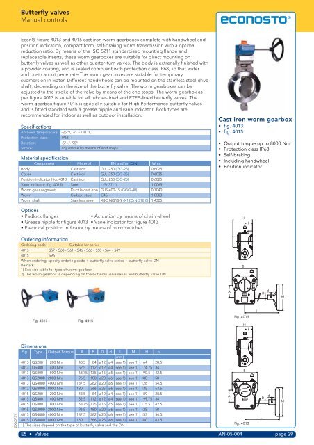
<strong>Butterfly</strong> <strong>valves</strong><br />
Manual controls<br />
<strong>Econ®</strong> figure 4013 and 4015 cast iron worm gearboxes complete with handwheel and<br />
position indication, compact form, self-braking worm transmission with a optimal<br />
reduction ratio. By means of the ISO 5211 standardised mounting flange and<br />
replaceable inserts, these worm gearboxes are suitable for direct mounting on<br />
butterfly <strong>valves</strong> as well as other quarter-turn <strong>valves</strong>. The body is extrenally finished with<br />
a powder coating, and is sealed compliant with protection class IP68, so that water<br />
and dust cannot penetrate.The worm gearboxes are suitable for temporary<br />
submersion in water. Different handwheels can be mounted on the stainless steel drive<br />
shaft, depending on the size of the butterfly valve. The worm gearboxes can be<br />
adjusted to the stroke of the valve by means of the end stops. The worm gearbox as<br />
per figure 4013 is suitable for all rubber-lined and PTFE-lined butterfly <strong>valves</strong>. The<br />
worm gearbox figure 4015 is specially suitable for High Performance butterfly <strong>valves</strong><br />
and is fitted standard with a grease nipple and vane indicator. Both types are<br />
recommended for indoor as well as outdoor installation.<br />
Specifications<br />
Ambient temperature: -25 °C -/- +110 °C<br />
Protection class: IP68<br />
Rotation: -5° -/- 95°<br />
Stroke: adjustable by means of end stops<br />
Material specification<br />
Component Material EN and/or (DIN) W.nr.<br />
Body Cast iron GJL-250 (GG-25) 0.6025<br />
Cover Cast iron GJL-250 (GG-25) 0.6025<br />
Position indicator (fig. 4013) Cast iron GJL-250 (GG-25) 0.6025<br />
Vane indicator (fig. 4015) Steel - (St.37-1) 1.0065<br />
Worm gear segment Ductile cast iron GJS-400-15 (GGG-40) 0.7040<br />
Worm Carbon steel C45 1.0503<br />
Worm shaft Stainless steel X8CrNiS18-9 (X12CrNiS18 8) 1.4305<br />
Options<br />
• Padlock flanges • Actuation by means of chain wheel<br />
• Grease nipple for figure 4013 • Vane indicator for figure 4013<br />
• Electrical position indicator by means of microswitches<br />
Ordering information<br />
Ordering code Suitable for series<br />
4013 S57 - S60 - S61 - S46 - S66 - S58 - S64 - S49<br />
4015 S96<br />
When ordering, specify ordering code + butterfly valve series + butterfly valve DN<br />
Remark:<br />
1) See size table for type of worm gearbox<br />
2) The worm gearbox is depending on the butterfly valve series and butterfly valve DN<br />
Dimensions<br />
Fig. Type Output Torque A B D d L M H h<br />
[mm]<br />
4013 QS200 200 Nm 43.5 84 ø12 ø4 see 1) see 1) 64 28.5<br />
4013 QS400 400 Nm 52.5 112 ø12 ø4 see 1) see 1) 74.75 34<br />
4013 QS800 800 Nm 68.75 135 ø15 ø5 see 1) see 1) 90.5 42.5<br />
4013 QS2000 2000 Nm 96.5 180 ø20 ø6 see 1) see 1) 100 50<br />
4013 QS4000 4000 Nm 137.5 282 ø20 ø6 see 1) see 1) 128 54.5<br />
4013 QS8000 8000 Nm 180 366 ø25 ø6 see 1) see 1) 135 63.5<br />
4015 QS200 200 Nm 43.5 84 ø12 ø4 see 1) see 1) 89 28.5<br />
4015 QS400 400 Nm 52.5 112 ø12 ø4 see 1) see 1) 99.75 34<br />
4015 QS800 800 Nm 68.75 135 ø15 ø5 see 1) see 1) 115.5 42.5<br />
4015 QS2000 2000 Nm 96.5 180 ø20 ø6 see 1) see 1) 125 50<br />
4015 QS4000 4000 Nm 137.5 282 ø20 ø6 see 1) see 1) 153 54.5<br />
4015 QS8000 8000 Nm 180 366 ø25 ø6 see 1) see 1) 160 63.5<br />
1) The sizes depend on the type of butterfly valve and the DN.<br />
Cast iron worm gearbox<br />
• fig. 4013<br />
• fig. 4015<br />
• Output torque up to 8000 Nm<br />
• Protection class IP68<br />
• Self-braking<br />
• Including handwheel<br />
• Position indicator<br />
E5 • Valves AN-05-004 page 29<br />
A<br />
A<br />
SHUT<br />
SHUT<br />
H<br />
B<br />
OPEN<br />
Fig. 4015<br />
OPEN<br />
h<br />
H<br />
h<br />
B<br />
Fig. 4013<br />
SHUT<br />
SHUT<br />
L<br />
L<br />
D<br />
D<br />
d<br />
d<br />
M<br />
M