resilient seat wafer valves - Fives North American Combustion, Inc.
resilient seat wafer valves - Fives North American Combustion, Inc.
resilient seat wafer valves - Fives North American Combustion, Inc.

Create successful ePaper yourself
Turn your PDF publications into a flip-book with our unique Google optimized e-Paper software.
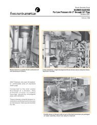
FEATURES:<br />
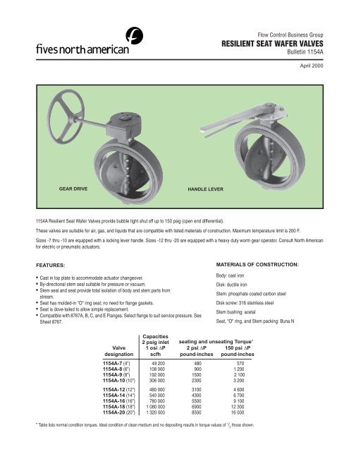
GEAR DRIVE HANDLE LEVER<br />
1154A Resilient Seat Wafer Valves provide bubble tight shut off up to 150 psig (open end differential).<br />
• Cast in top plate to accommodate actuator changeover.<br />
• By-directional stem seal suitable for pressure or vacuum.<br />
• Stem seal and <strong>seat</strong> provide total isolation of body and stem parts from<br />
stream.<br />
• Seat has molded-in "O" ring seal; no need for fl ange gaskets.<br />
• Seat is dove-tailed to allow simple replacement.<br />
• Compatible with 8767A, B, C, and E Flanges. Select fl ange to suit service pressure. See<br />
Sheet 8767.<br />
Capacities<br />
2 psig inlet <strong>seat</strong>ing and un<strong>seat</strong>ing Torque*<br />
Valve 1 osi ΔP 2 psi ΔP 150 psi ΔP<br />
designation scfh pound.inches pound.inches<br />
1154A-7 (4") 49 200 480 570<br />
1154A-8 (6") 108 000 900 1 200<br />
1154A-9 (8") 192 000 1500 2 100<br />
1154A-10 (10") 306 000 2300 3 200<br />
1154A-12 (12") 480 000 3100 4 600<br />
1154A-14 (14") 540 000 4300 6 700<br />
1154A-16 (16") 780 000 5500 9 100<br />
1154A-18 (18") 1 080 000 6900 12 300<br />
1154A-20 (20") 1 320 000 8500 16 000<br />
* Table lists normal condition torques. Ideal condition of clean medium and no depositing results in torque values of 1 / 2 those shown.<br />
Flow Control Business Group<br />
RESILIENT SEAT WAFER VALVES<br />
Bulletin 1154A<br />
These <strong>valves</strong> are suitable for air, gas, and liquids that are compatible with listed materials of construction. Maximum temperature limit is 200 F.<br />
April 2000<br />
Sizes -7 thru -10 are equipped with a locking lever handle. Sizes -12 thru -20 are equipped with a heavy duty worm gear operator. Consult <strong>North</strong> <strong>American</strong><br />
for electric or pneumatic actuators.<br />
MATERIALS OF CONSTRUCTION:<br />
Body: cast iron<br />
Disk: ductile iron<br />
Stem: phosphate coated carbon steel<br />
Disk screw: 316 stainless steel<br />
Stem bushing: acetal<br />
Seat, "O" ring, and Stem packing: Buna N
FIVES NORTH AMERICAN COMBUSTION, INC. Bulletin 1154A, 4-00<br />
Page 2<br />
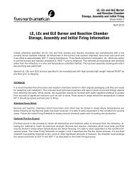
Open pipework to allow free valve<br />
entry. Rotate valve stem clockwise to<br />
position disk edge about 3 /8" from the<br />
outside edge of the <strong>seat</strong> (semi-closed<br />
position). This will protect disk edge,<br />
and reduce rubber interface and initial<br />
torque build-up.<br />
DO NOT install valve with pipework<br />
spread insuffi ciently. This will damage<br />
the valve <strong>seat</strong>. Installing valve with<br />
disk in full-open position as shown,<br />
will impact fl ange and damage disk<br />
edge.<br />
Insert the valve between the fl anges<br />
and assemble the valve body to the<br />
fl anges with all required fl ange bolts.<br />
DO NOT USE FLANGE GASKETS.<br />
1154A Valve <strong>seat</strong> has a molded-in<br />
O-ring that effects a positive seal<br />
against standard ANSI fl ange faces.<br />
(N.A. style 8767A, B, C, and E.)<br />
DO NOT install with disk in fully closed<br />
position. This will cause <strong>seat</strong> distortion.<br />
When fl ange bolts are tightened,<br />
rubber will close around disk edge<br />
creating excessive torque in initial<br />
operation.<br />
Turn the disk to full-open position.<br />
Center the valve body to the fl anges,<br />
and tighten the bolts handtight.<br />
Slowly close the valve to check for adequate<br />
disk clearance. Return disk to full-open position<br />
and cross-tighten all bolts to proper torque<br />
specifi cation.<br />
INCORRECT pipe alignment will<br />
cause interference between disk edge<br />
and fl ange face creating leakage,<br />
excessive torque and damage to disk<br />
and <strong>seat</strong>.
fIVES NORTH AMERICAN COMBUSTION, INC. Bulletin 1154A, 4-00<br />
Page 3<br />
INSTALLATION AND MAINTENANCE INSTRUCTIONS<br />
Flange and Pipe Compatibility: 1154A Valves are used between all types of ANSI 125 and 150 pound fl at or raised face fl anges.<br />
Flange gaskets are unnecessary as 1154A Valve <strong>seat</strong> face design eliminates the need for gaskets. Lined pipe, heavy wall pipe, or fl anges<br />
must have a minimum allowable inside diameter "K" at the centered body face to clear disk sealing edge when opening valve.<br />
Installation Information: 1154A Valves are nondirectional and will control fl ow equally well in either direction. For best results<br />
in dirty service, position the valve assembly to have stem in horizontal position and lower disk edge to open in downstream direction.<br />
To install valve between existing ANSI fl anges, fl anges must be spread suffi ciently before placing valve in position to prevent distortion<br />
and/or damage to the sealing face of <strong>seat</strong>.<br />
In new construction using ANSI welding type fl anges, the following method of installation has proven benefi cial. With the disk in nearly<br />
closed position, center each companion fl ange bore to the body face bore, span valve body with fl ange bolting, and make-up the bolting.<br />
Use fl ange-body-fl ange assembly for fi t-up and centering to pipe. Tack weld the fl anges to pipe. Remove bolting and valve assembly<br />
from between fl anges. Important: Do not fi nish weld the fl anges to pipe with valve bolted between fl anges as<br />
this will result in serious heat damage to <strong>seat</strong>. Finish welding the fl anges to pipe and allow fl anges to cool completely.<br />
Installation Instructions: Observe that the disk sealing edge is in line with keyway in stem. Rotate stem clockwise to position<br />
disk within body at least 3 /8" away from body face. After spreading the fl anges, center valve body between fl anges and span valve body<br />
with all fl ange bolts possible. Turn disk to full-open position. Next, maintain the valve to fl ange alignment while gradually removing the<br />
fl ange spreaders and tightening fl ange bolting handtight. Slowly close the valve clockwise to check for adequate disk clearance. Return<br />
the disk to the full-open position and cross-tighten all bolting to proper torque specifi cation. Again, check for adequate disk clearance.<br />
If installation is satisfactory, valve is ready for service after installing valve operator or actuator.<br />
Maintenance: Routine maintenance or lubrication is not required.<br />
Repairs: 1154A Valves are fi eld repairable. If in time it is necessary to replace certain parts, valve must be removed from the line.<br />
Proceed by turning disk to the nearly closed position, loosen all fl ange bolting, remove necessary bolting, spread the fl anges if necessary,<br />
and remove valve from between fl anges.<br />
Valve Disassembly: Turn disk to the almost open position. Proceed by removing operator or actuator, disk screws with "O" rings,<br />
stem, packing and bushing. Remove disk by pulling or "rolling" the disk out of <strong>seat</strong> bore. To remove <strong>seat</strong> from body, pry under both<br />
<strong>seat</strong> edges at one point, collapse <strong>seat</strong> into the shape of a round bottom heart confi guration ( ), and pull the <strong>seat</strong> out of body bore.<br />
Discard parts to be replaced.<br />
Valve Assembly: Clean all reusable parts. If possible, use Silicone base oil or lubricant to facilitate assembly. Collapse <strong>seat</strong> into the<br />
shape of a round bottom heart confi guration ( ), fi rmly place "bottom" part of <strong>seat</strong> into position taking care to align lower stem holes,<br />
snap <strong>seat</strong> into position within the body, and check all stem holes for proper alignment. Install disk with the screw holes toward body top<br />
plate and align stem holes. Install packing, bushing, and stem. Use a rotary downward pressure on stem to facilitate assembly while<br />
paying particular attention that the <strong>seat</strong> is not damaged due to any misalignment of stem holes. Align the counterdrilled portion of the<br />
stem screw holes with disk screw holes. Place "O" rings on disk screws. Install disk screws and tighten securely.<br />
β<br />
β
X<br />
B.C.<br />
T<br />
N<br />
J<br />
G<br />
-9 thru -14<br />
W – tap size<br />
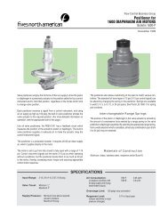
DIMENSIONS<br />
inches<br />
keyway J<br />
H – dia. H – dia.<br />
-16 thru -20<br />
Valve<br />
designation A B C D E F G H J K L N P T V<br />
1154A-7 4 41 / 6 8 7 / 7 2 8 1 / 4 1 8 1 / 4<br />
1154A-8 6 61 / 8 8 3 / 7 4 15 / 2 16 1 / 4 1 4 1 / 4<br />
1154A-9 8 81 / 11 9 8 3 / 2 16 1 / – 1 2 5 / 8<br />
1154A-10 10 101 / 13 8 3 / 10 8 1 / 2 2 13 / – 1 16 5 / 8<br />
5<br />
/8 17 / 3 16 7 / 11 – – – 4 8 13 / 16<br />
5<br />
/8 17 / 6 11 – – – 5 16 7 / 8<br />
3<br />
/4 115 / 8 16 – – – 6 16 15 / 16<br />
7<br />
/8 1 / 10 16 – – – 8 8 3 / 8<br />
1154A-12 12 12 1 / 8 16 1 / 8 12 1 / 16 3 1 / 8 – – 1 1 / 8 1 1 / 4 12 – 1 5 / 8 10 – 9 13 / 16<br />
1154A-14 14 13 1 / 4 17 3 / 4 13 1 / 8 3 5 / 8 – – 1 3 / 8 1 1 / 2 13 1 / 4 – 2 1 / 4 16 – 10 3 / 8<br />
1154A-16 16 15 1 / 4 20 1 / 4 14 1 / 2 4 1 / 8 6 – 1 1 / 2 1 1 / 2 15 – 2 7 / 16 16 3 1 / 8 12 1 / 8<br />
1154A-18 18 17 1 / 4 21 5 / 8 16 4 5 / 8 8 – 2 2 16 7 / 8 – 3 16 4 5 / 8 13<br />
1154A-20 20 19 1 / 4 23 7 / 8 17 1 / 2 5 1 / 8 8 – 2 2 18 3 / 4 – 3 16 4 5 / 8 15<br />
Valve wt, lb<br />
designation W X w/operator keyway<br />
1154A-7 5 /8- 11 UNC – 15 –<br />
1154A-8 3 /4- 10 UNC – 21 –<br />
1154A-9 3 /4- 10 UNC 11 3 / 4 34 –<br />
1154A-10 7 /8 -9 UNC 14 1 / 4 59 –<br />
7 1154A-12 /8-9 UNC 17 94 –<br />
1154A-14 1-8 UNC 183 / 147 –<br />
4<br />
1154A-16 1-8 UNC 211 3 3 / 218 /8 × /8<br />
4<br />
1154A-18 1 / 7 UNC 22 8- 3 1 / 297 /2 × 4 3 / 8 Flat<br />
1154A-20 1 1 / 7 UNC 25 390 /2 × 8- 3 / 8 Flat<br />
P<br />
A = pipe size<br />
sizes -7 & 8: H dia. × J fl ats<br />
K = minimum allowable pipe or fl ange ID<br />
7 thru -14<br />
DIMENSIONS SHOWN ARE SUBJECT TO CHANGE. PLEASE OBTAIN CERTIFIED PRINTS FROM FIVES NORTH AMERICAN COMBUSTION, INC.<br />
IF SPACE LIMITATIONS OR OTHER CONSIDERATIONS MAKE EXACT DIMENSION(S) CRITICAL.<br />
WARNING: Situations dangerous to personnel and property may exist with the operation and maintenance of an combustion equipment.The presence of fuels, oxidants, hot and cold<br />
combustion products, hot surfaces, electrical power in control and ignition circuits, etc.,are inherent with any combustion application. Parts of this product may exceed 160F in operation<br />
and present a contact hazard. <strong>Fives</strong> <strong>North</strong> <strong>American</strong> urges compliance with National Safety Standards and insurance Underwriters recommendations, and care in operation.<br />
<strong>Fives</strong> <strong>North</strong> Amercian <strong>Combustion</strong>, <strong>Inc</strong>., 4455 East 71st Street, Cleveland, OH 44105 USA, Phone 216.271.6000<br />
Fax 216.641.7852 email: fna.sales@fi vesgroup.com • www.fi vesgroup.com/fi vesna<br />
Printed in USA FNA 4-00-B1154A<br />
L<br />
F<br />
H<br />
E<br />
stem<br />
Bulletin 1154A<br />
Page 4<br />
C<br />
B<br />
K<br />
G<br />
D<br />
V