TBH Plunger valve Type PLV DN200(8”)-1400(55”) PN6-25
TBH Plunger valve Type PLV DN200(8”)-1400(55”) PN6-25
TBH Plunger valve Type PLV DN200(8”)-1400(55”) PN6-25

You also want an ePaper? Increase the reach of your titles
YUMPU automatically turns print PDFs into web optimized ePapers that Google loves.
<strong>TBH</strong>YDRO<br />
tbhydro.com.pl<br />
Description:<br />
<strong>Plunger</strong> <strong>valve</strong> <strong>Type</strong> <strong>PLV</strong><br />
<strong>DN200</strong>(<strong>8”</strong>)-<strong>1400</strong>(<strong>55”</strong>) <strong>PN6</strong>-<strong>25</strong><br />
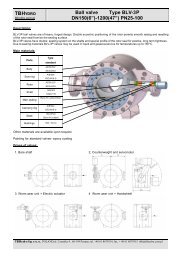
<strong>PLV</strong> plunger <strong>valve</strong>s have compact shape and good head loss coefficient compared to other regulating and shut-off devices.<br />
The outer and the inner bodies are formed in such a way that the cross section of flow decreases continuously from the inlet<br />
side to the sealing point. The piston moves axial to the main flow and perpendiculary to the seat ring.<br />
<strong>PLV</strong> plunger <strong>valve</strong>s are used as shut-off and regulating devices in pressurized piping systems.<br />
Due to sealing materials <strong>PLV</strong> <strong>valve</strong>s may be used in liquid and gaseous service for temperatures up to 150°C.<br />
Main materials:<br />
Parts<br />
Body<br />
Piston<br />
Clamping<br />
ring<br />
Ring<br />
Shaft<br />
Seals<br />
<strong>Type</strong><br />
standard<br />
ASTM 537<br />
S335J2G3<br />
AISI304<br />
X5CrNi18-9<br />
AISI304<br />
X5CrNi18-9<br />
AISI304<br />
X5CrNi18-9<br />
AISI403<br />
X20Cr13V<br />
Novothan<br />
Buna N (rubber)<br />
Bushings INA / Deva<br />
Main<br />
sealing<br />
Buna N /<br />
polyurethan<br />
Other materials are available upon request<br />
Painting for standard <strong>valve</strong>s- epoxy coating<br />
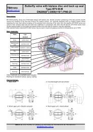
Drives of <strong>valve</strong>s:<br />
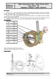
1. Worm gear unit + Electric actuator Outlet section:<br />
I - with cut-off edge and sudden entlargement<br />
of cross sectional area at the seat<br />
2. Worm gear unit + Handwheel<br />
III - with perforated<br />
cylinder<br />
II - with slotted<br />
sleeve<br />
<strong>TBH</strong>ydro S p. z o. o. POLAND,ul. Czernika 4, 60-194 Poznan, tel. +48 61 8679314, fax. + 48 61 8679315 tbh@tbhydro.com.pl<br />
1/2
<strong>TBH</strong>YDRO<br />
tbhydro.com.pl<br />
<strong>Plunger</strong> <strong>valve</strong> <strong>Type</strong> <strong>PLV</strong><br />
<strong>DN200</strong>(<strong>8”</strong>)-<strong>1400</strong>(<strong>55”</strong>) <strong>PN6</strong>-<strong>25</strong><br />
Dimensions and weights for standard range of <strong>PLV</strong>- plunger <strong>valve</strong>s (other sizes and pressure ratings are available upon request).<br />
DN BL<br />
A B D Weight<br />
drive 1<br />
<strong>PN6</strong> PN10 PN16 PN<strong>25</strong><br />
Weight<br />
drive 2<br />
A B D Weight<br />
drive 1<br />
<strong>TBH</strong>ydro S p. z o. o. POLAND,ul. Czernika 4, 60-194 Poznan, tel. +48 61 8679314, fax. + 48 61 8679315 tbh@tbhydro.com.pl 2/2<br />
Weight<br />
drive 2<br />
A B D Weight<br />
drive 1<br />
Weight<br />
drive 2<br />
A B D Weight<br />
drive 1<br />
[mm] [mm] [mm] [mm] [mm] [kG] [kG] [mm] [mm] [mm] [kG] [kG] [mm] [mm] [mm] [kG] [kG] [mm] [mm] [mm [kG] [kG]<br />
200 555 560 180 415 <strong>25</strong>0 230 560 180 415 280 <strong>25</strong>0 560 180 415 300 280 560 180 415 350 330<br />
<strong>25</strong>0 710 600 180 450 280 260 600 180 450 300 280 600 180 450 320 300 600 180 450 400 380<br />
300 850 650 180 500 370 340 650 180 500 385 360 650 180 500 410 380 650 180 500 490 470<br />
350 950 690 180 550 430 400 690 180 550 460 440 690 180 550 505 485 690 180 550 570 550<br />
400 1050 770 180 700 600 580 770 180 700 630 600 770 180 700 730 710 770 180 700 900 880<br />
450 1150 770 180 700 700 690 770 180 700 760 740 770 180 700 890 870 770 180 700 1080 1050<br />
500 1<strong>25</strong>0 820 180 800 800 790 820 180 800 860 840 820 180 800 1020 1000 820 180 800 1230 1200<br />
600 1450 920 180 1000 1230 1210 920 180 1000 1410 1390 920 180 1000 1680 1660 920 180 1000 2040 2020<br />
700 1600 970 180 1100 1680 1660 970 180 1100 1780 1760 980 180 1100 2080 2050 980 180 1100 <strong>25</strong>50 <strong>25</strong>20<br />
800 1800 1080 180 1300 2000 1970 1080 180 1300 2390 2370 1090 180 1300 2840 2800 1090 180 1300 3510 3470<br />
900 2000 1130 180 <strong>1400</strong> 3160 3140 1140 180 <strong>1400</strong> 3330 3300 1140 180 <strong>1400</strong> 3460 3400 1140 180 <strong>1400</strong> 4230 4200<br />
1000 2200 1180 180 1500 3780 3760 1190 180 1500 4000 3970 1190 180 1500 4240 4200 <strong>1400</strong> 180 1500 5300 5240<br />
1200 2400 1340 180 1800 5700 5680 1350 180 1800 6180 6150 1350 180 1800 6430 6400 1500 180 1800 7500 7600<br />
<strong>1400</strong> 3000 <strong>1400</strong> 180 2200 15850 15700 1500 180 2200 16370 16200 1600 180 2200 16500 16400 1700 180 2200 17700 17500<br />
Flange in accordance with ISO / DIN<br />
Flanges in accordance with ANSI and MSS available on request.<br />
Dimensions and weights are preliminary only. Final dimensions and weights will be established after detail design of each <strong>valve</strong> is completed.<br />
Weight<br />
drive 2