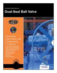
DUAL-SEAL BALL VALVE
DUAL-SEAL BALL VALVE
DUAL-SEAL BALL VALVE

You also want an ePaper? Increase the reach of your titles
YUMPU automatically turns print PDFs into web optimized ePapers that Google loves.
WOM<br />
OPERATING & MAINTENANCE<br />
PROCEDURES<br />
FOR<br />
<strong>DUAL</strong>-<strong>SEAL</strong> <strong>BALL</strong> <strong>VALVE</strong><br />
FOR PRODUCTION, PIPELINE, TOP-SIDE AND UNDERGROUND<br />
STORAGE SERVICES<br />
Manual Identification Number: OPM-316, Rev. 4<br />
Revised February, 2010<br />
A429EN1.08 Rev.4
TABLE OF CONTENTS<br />
DESCRIPTION SECTION<br />
Operating Procedures for a Model 30 and<br />
Model 30-D Dual Seal Ball Valve................................................................I<br />
Maintenance & Lubrication for Model 30<br />
and Model 30-D Dual Seal Ball Valve......................................................II<br />
Trouble Shooting & Routine Functional Testing<br />
for Model 30 and Model 30-D Dual Seal Ball Valve ............................ III<br />
Valve Storage .............................................................................................. IV<br />
EHSR Requirement of Warning & Caution ............................................ V<br />
Appendices<br />
Maintenance Schedule............................................................................ A<br />
Assembly Drawings.................................................................................B<br />
Bill of Materials........................................................................................ C<br />
API Specification 6D Testing Procedures............................................ D<br />
General Design Standard........................................................................E<br />
A429EN1.08 Rev.4
SECTION I<br />
A429EN1.08 Rev.4
WOM<br />
MODEL 30 / MODEL 30-D<br />
<strong>DUAL</strong> <strong>SEAL</strong><br />
<strong>BALL</strong> <strong>VALVE</strong><br />
Size: All<br />
Pressure Class: All<br />
Material Class: All<br />
Mode of Operation: All<br />
OPERATING PROCEDURES<br />
OPM-316<br />
REVISION: 4<br />
SECTION: I<br />
PAGE: 1 OF 5<br />
The Model 30 and Model 30-D Dual-Seal Ball Valve use a trunnion mounted ball design to<br />
achieve an upstream seal. The Model 30 Dual-Seal valve is bi-directional, and incorporates<br />
W.O.M.’s patented Dual-Seal design of two independent seals on each side of the ball for<br />
extended valve life and additional safety.<br />
The Model 30-D use the same upstream Dual-Seal design, but the addition of a modified<br />
secondary seal on the downstream side now gives the valve a third seal on the downstream<br />
side of the ball. The 30-D also has a “preferred direction of flow arrow” indicated by a stainless<br />
steel tag mounted on the side of the body.<br />
A. GENERAL OPERATING INSTRUCTIONS:<br />
Ball valves should never be used to "throttle" line fluid. Throttling any<br />
ball valve will result in seat and/or ball damage. This valve should be fully opened and fully<br />
closed.<br />
To Operate:<br />
1. To OPEN, rotate the lever or gear box handwheel counter-clockwise the valve has<br />
moved 90 degrees and strong resistance is felt. There is a shoulder, the “end-stop,” on<br />
the valve which gives the valve a positive stop in the open position. Worm gear operated<br />
valves will have a position indication cast on to the top plate of the worm gear. These<br />
valves will travel only turn ¼ turn or 90 degrees. Reverse direction to CLOSE.<br />
2. Power-opening with an electric actuator – use the open / closed stops on the valve or on<br />
the gear box to fully open and close the valve. The electric actuator should be set to stop<br />
with torque limits.<br />
A429EN1.08 Rev.4
WOM<br />
MODEL 30 / MODEL 30-D<br />
<strong>DUAL</strong> <strong>SEAL</strong><br />
<strong>BALL</strong> <strong>VALVE</strong><br />
OPERATING PROCEDURES<br />
OPM-316<br />
REVISION: 4<br />
SECTION: I<br />
PAGE: 2 OF 5<br />
B. Operation Instructions for Double Block and Bleed using the Bleed Fitting:<br />
The W.O.M. Dual-Seal Ball Valve is a Double Block and Bleed valve (DBB) Double Block<br />
and Bleed can be verified by following API 6D test procedures. With the line under<br />
pressure, the valve center body cavity can be vented to the atmosphere and completely<br />
de-pressurized with the ball in either the open or closed positions.<br />
After venting, if no additional line pressure enters the valve, the seals have been proven to<br />
be intact.<br />
Bleed the body cavity pressure through the vent (bleeder) fitting located in the upper<br />
quadrant of the ball valve’s center section. This fitting has two venting ports 180 degrees<br />
opposite each other. Refer to Drawings “A” & “B”.<br />
Figure 4 (4” & Larger Ball Valves)<br />
Drawing “B” - 4” valve & Up<br />
Body Vent (Bleeder) Fitting<br />
A429EN1.08 Rev.4
WOM<br />
MODEL 30 / MODEL 30-D<br />
<strong>DUAL</strong> <strong>SEAL</strong><br />
<strong>BALL</strong> <strong>VALVE</strong><br />
OPERATING PROCEDURES<br />
OPM-316<br />
REVISION: 4<br />
SECTION: I<br />
PAGE: 3 OF 5<br />
1. 4” and larger valves: To open the vent ports use a wrench on the upper (smaller) hex<br />
head stem of the fitting and turn the wrench counter-clockwise*. This will allow any<br />
trapped pressure in the body to vent to atmosphere.<br />
Figure 3 (2” & 3” Ball Valves)<br />
Drawing “A” - 2” & 3” valve<br />
Body Vent (Bleeder) Fitting<br />
2. 2” and 3” valves: same procedure as for 4” and larger, but the vent fitting uses an allen<br />
head wrench to open and close the ports.<br />
3. Close the vent fitting by turning the small hex head stem, (or allen head)<br />
clockwise until it snugs tight. This fitting must be in the closed position<br />
at all times other than for block and bleed tests.<br />
* Caution : When turning the smaller hex head, make sure the threaded body of the<br />
fitting does not unthread out of the ball valve center section. You may need<br />
to put a back-up wrench on the larger hex head. (See Figures 3 & 4)<br />
** ALWAYS USE EYE PROTECTION DURING THIS PROCEDURE<br />
C. VENTING:<br />
No WOM ball valve can trap pressure in the body. All valves are self-relieving.<br />
A429EN1.08 Rev.4
WOM<br />
MODEL 30 / MODEL 30-D<br />
<strong>DUAL</strong> <strong>SEAL</strong><br />
<strong>BALL</strong> <strong>VALVE</strong><br />
OPERATING PROCEDURES<br />
OPM-316<br />
REVISION: 4<br />
SECTION: I<br />
PAGE: 4 OF 5<br />
In the Model 30, the excess pressure bleeds to the side of the valve with the lowest<br />
pressure. For example: if you have 1000 psi on the upstream side of the valve and 500 psi<br />
on the downstream side, the excess pressure in the body cavity will bleed to the low<br />
pressure (downstream) side. (See Figure 1)<br />
Figure 1 Figure 2<br />
In the Model 30-D, with the Third Seal, the valve will vent excess pressure to the upstream or<br />
pressure side of the valve. At zero line pressure, it could hold approximately 200 psi to 300 psi<br />
inside the body cavity. Precaution should be taken to bleed off this retained pressure by, a.<br />
Opening the vent fitting,<br />
b. Using a pressure relief tool (see below) on one of the body grease fittings or<br />
c. By cycling the valve to bleed the body cavity pressure to the line. (See Figure 2 above)<br />
A429EN1.08 Rev.4
WOM<br />
MODEL 30 / MODEL 30-D<br />
<strong>DUAL</strong> <strong>SEAL</strong><br />
<strong>BALL</strong> <strong>VALVE</strong><br />
OPERATING PROCEDURES<br />
Pressure Relief Tool for use with grease fittings<br />
OPM-316<br />
REVISION: 4<br />
SECTION: I<br />
PAGE: 5 OF 5<br />
NOTES:<br />
1. Always follow your Company’s specified operating instructions for the media being produced.<br />
2. Assembly drawing of Model 30 Ball Valve<br />
3. Details of stem sealing area<br />
4. Bill of Material for Ball Valve.<br />
Stem Seal Details & Bill of Materials<br />
A429EN1.08 Rev.4
SECTION II<br />
A429EN1.08 Rev.4
WOM<br />
MODEL 30 / MODEL 30-D<br />
<strong>DUAL</strong> <strong>SEAL</strong><br />
<strong>BALL</strong> <strong>VALVE</strong><br />
Size: All<br />
Pressure Class: All<br />
Material Class: All<br />
Mode of Operation: All<br />
MAINTENANCE<br />
AND<br />
LUBRICATION<br />
OPM-316<br />
REVISION: 4<br />
SECTION: II<br />
PAGE: 1 OF 5<br />
A. GENERAL INSTRUCTIONS :<br />
1. Preventive Maintenance is based on Operating Conditions and the Company’s own<br />
Preventative Maintenance Program.<br />
2. The stem seals are lubricated at the factory. No maintenance needed for normal<br />
operation.<br />
3. Model 30 and Model 30-D uses two sets of dry permanently lubricated bearings, the<br />
upper trunnion and one on the lower trunnion. These bearings do not require lubrication<br />
under normal operating procedures.<br />
4. Worm gear - The worm gear operator needs annual additions of heavy non-pourable<br />
grease to lubricate the worm gear shaft. Grease can be injected thru the grease zert<br />
located on the gear housing, or you can unbolt the gear box and pry off the cover plate.<br />
Add grease until the area is nearly full. Grease will help keep water from accumulating<br />
in the gear box. NOTE: In freezing weather, any water in the gear box can freeze and<br />
damage the box.<br />
B. SEAT LUBRICATION :<br />
It is not necessary to lubricate the seats during normal operations of this valve. The<br />
seats are designed for the resilient seals to float against the ball without requiring<br />
grease.<br />
Caution : There will be some trapped pressure in the body cavity (from the last<br />
open/close cycling) If the valve is handling H2S or similar toxic materials,<br />
appropriate safety precautions and protective equipment should be used.<br />
Consult your safety coordinator if unsure.<br />
A429EN1.08 Rev.4
WOM<br />
MODEL 30 / MODEL 30-D<br />
<strong>DUAL</strong> <strong>SEAL</strong><br />
<strong>BALL</strong> <strong>VALVE</strong><br />
MAINTENANCE<br />
AND<br />
LUBRICATION<br />
OPM-316<br />
REVISION: 4<br />
SECTION: II<br />
PAGE: 2 OF 5<br />
Follow this sequence: (preferred, but not essential to bleed off body pressure)<br />
1. Body vent fitting is the MIDDLE body fitting. Note: Use the instructions in Section C<br />
of the Operating Instructions to de-pressurize the valve. If you cannot de-pressurize<br />
the valve, you will need to use sufficient grease gun pressure to over come the<br />
pressure in the valve, plus the pressure required to move the grease out of the<br />
grease gun. In cold weather, grease will thicken and require more pressure to pump<br />
through the gun.<br />
Caution : Never remove any fitting or plug that appears to be threaded into the<br />
body without first making sure there is no pressure beneath the fitting. There may<br />
be trapped pressure underneath the fitting that could eject it out of the threads<br />
with deadly consequences.<br />
2. When body cavity is completely vented, remove the vent cap from the grease fitting<br />
(See drawing “E”) on the pressure side seat. Do not remove the entire grease fitting<br />
which is threaded into the valve end connection. (A ball check inside the fitting<br />
prevents pressure loss, but will accept grease input).<br />
Drawing “E” - Vented Cap Body Grease Fitting<br />
Note : There is no buried check valve beneath ANY grease fitting of a WOM Valve.<br />
A429EN1.08 Rev.4
WOM<br />
MODEL 30 / MODEL 30-D<br />
<strong>DUAL</strong> <strong>SEAL</strong><br />
<strong>BALL</strong> <strong>VALVE</strong><br />
MAINTENANCE<br />
AND<br />
LUBRICATION<br />
OPM-316<br />
REVISION: 4<br />
SECTION: II<br />
PAGE: 3 OF 5<br />
3. Connect a high pressure (10,000psi) grease gun to seat grease fitting on the<br />
pressure side of the valve.<br />
4. Pump lubricant into the valve seat. The grease will travel around the entire “annulus”<br />
between the Primary and Secondary Seals, filling the area up between the O.D.<br />
elastomers. This will lubricate the seals and allow them to float, as designed, if you<br />
have determined that they are not sealing against the ball.<br />
5. Never exceed the working pressure of the valve when pumping grease into the<br />
seats. Refer to Appendix E, Table 2.1 from API 6D.<br />
6. Remove grease gun<br />
7. Replace vent cap on grease fitting and lightly tighten.<br />
C. Draining the valve to remove moisture:<br />
Depending on climate and your Company’s standard operating<br />
procedures, you may need to periodically drain accumulated water and contaminants<br />
from the center body cavity of the valve. Choose the lowest body fitting to the ground,<br />
depending on the orientation of the valve. It will either be the center or middle body vent<br />
fitting, or the lower trunnion fitting. The lower trunnion fitting is typically a solid drain<br />
plug. (See Drawing C)<br />
Drawing “C”<br />
Solid Cavity Drain Plug - all valve sizes<br />
A429EN1.08 Rev.4
WOM<br />
MODEL 30 / MODEL 30-D<br />
<strong>DUAL</strong> <strong>SEAL</strong><br />
<strong>BALL</strong> <strong>VALVE</strong><br />
MAINTENANCE<br />
AND<br />
LUBRICATION<br />
OPM-316<br />
REVISION: 4<br />
SECTION: II<br />
PAGE: 4 OF 5<br />
As an option, this plug can be replaced with a quarter turn drain valve. Removing solid<br />
drain plug allows water and sediment to drain from valve. Be sure this plug or a valve is<br />
re-installed prior to commissioning valve.<br />
Do not remove this plug without first venting valve body cavity to the atmosphere.<br />
D. Storage<br />
a. Place the valve in the full open position<br />
b. Inject grease in to each seat grease fitting until you see excess grease oozing out<br />
from between the ball and seat on the inside of the valve cavity (see instruction B<br />
under Seat Lubrication.)<br />
c. Coat the end connection seal surfaces with grease to prevent rust.<br />
d. Use flange covers to keep out debris.<br />
e. The valve should remain in the open position until installed.<br />
NOTES :<br />
1. Always follow your Company’s specified operating instructions for the media being<br />
produced.<br />
2. Assembly drawing of Model 30 Ball Valve<br />
3. Details of stem sealing area<br />
4. Bill of Material for Ball Valve<br />
5. Stem Packing Tag Drawing<br />
Stem Packing Tag<br />
A429EN1.08 Rev.4
WOM<br />
MODEL 30 / MODEL 30-D<br />
<strong>DUAL</strong> <strong>SEAL</strong><br />
<strong>BALL</strong> <strong>VALVE</strong><br />
MAINTENANCE<br />
AND<br />
LUBRICATION<br />
Stem Seal Detail & Bill of Materials<br />
OPM-316<br />
REVISION: 4<br />
SECTION: II<br />
PAGE: 5 OF 5<br />
A429EN1.08 Rev.4
SECTION III<br />
A429EN1.08 Rev.4
WOM<br />
MODEL 30 / MODEL 30-D<br />
<strong>DUAL</strong> <strong>SEAL</strong><br />
<strong>BALL</strong> <strong>VALVE</strong><br />
Size: All<br />
Pressure Class: All<br />
Material Class: All<br />
Mode of Operation: All<br />
TROUBLE SHOOTING AND<br />
ROUTINE PUNCTIONAL TESTING<br />
OPM-316<br />
REVISION: 4<br />
SECTION: III<br />
PAGE: 1 OF 4<br />
A. Stem Packing Troubleshooting:<br />
1. If you see slight weepage of valve contents coming from around the stem this is an<br />
indication of a slight stem packing leak. This may be corrected by injecting sealant into<br />
the stem packing fitting. Use the same procedures as adding grease in the seat grease<br />
fitting, instruction “B Maintenance instructions for injecting lube/sealant” into this area.<br />
(See Figure 5) Keep in mind that the area to inject grease in to is very small and a<br />
single stroke from a high pressure grease gun should inject enough grease to affect a<br />
seal. If the valve can be cycled, open and close it several times to help distribute the<br />
grease around the O.D. of the stem.<br />
A429EN1.08 Rev.4
WOM<br />
MODEL 30 / MODEL 30-D<br />
<strong>DUAL</strong> <strong>SEAL</strong><br />
<strong>BALL</strong> <strong>VALVE</strong><br />
TROUBLE SHOOTING AND<br />
ROUTINE PUNCTIONAL TESTING<br />
Figure 5<br />
OPM-316<br />
REVISION: 4<br />
SECTION: III<br />
PAGE: 2 OF 4<br />
A429EN1.08 Rev.4
WOM<br />
MODEL 30 / MODEL 30-D<br />
<strong>DUAL</strong> <strong>SEAL</strong><br />
<strong>BALL</strong> <strong>VALVE</strong><br />
TROUBLE SHOOTING AND<br />
ROUTINE PUNCTIONAL TESTING<br />
OPM-316<br />
REVISION: 4<br />
SECTION: III<br />
PAGE: 3 OF 4<br />
2. If you see a steady flow of valve contents coming from around the stem this may<br />
indicate significant damage to the stem seals. Use the same instructions above but Inject<br />
enough sealant into the stem packing fitting to reduce the amount of the leak until an<br />
authorized service representative can be consulted.<br />
B. Shell Testing<br />
The valve is to be shell tested in the PARTIAL OPEN position. The test is to be done as per API<br />
6D, latest edition.<br />
The shell test is to verify if the following seal points are intact and functioning properly:<br />
1. Body to Upper/Lower Trunnion gasket seals<br />
2. All Body Bleed Fittings<br />
3. Stem Seals<br />
If any of the above seal points appear to leak or are weeping, consult the WOM factory<br />
representative. (See Stem Seal Trouble Shooting at the beginning of this section.)<br />
C. Seat Testing<br />
The valve must be in the FULLY CLOSED position.<br />
The Seat Test is done in accordance with API 6D, latest edition.<br />
The Seat Test will verify if the following seal points are intact and functioning properly:<br />
1. The face seal of the seat against the ball.<br />
2. The seat to body seal where the outside diameter elastomer seals between the<br />
body and the seat assembly<br />
NOTES :<br />
1. Always follow your Company’s specified operating instructions for the media being<br />
produced.<br />
2. Assembly drawing of Model 30 Ball Valve<br />
3. Details of stem sealing area<br />
4. Bill of Material for Ball Valve.<br />
A429EN1.08 Rev.4
WOM<br />
MODEL 30 / MODEL 30-D<br />
<strong>DUAL</strong> <strong>SEAL</strong><br />
<strong>BALL</strong> <strong>VALVE</strong><br />
TROUBLE SHOOTING AND<br />
ROUTINE PUNCTIONAL TESTING<br />
Stem Seal Detail & Bill of Materials<br />
OPM-316<br />
REVISION: 4<br />
SECTION: III<br />
PAGE: 4 OF 4<br />
A429EN1.08 Rev.4
SECTION IV<br />
A429EN1.08 Rev.4
WOM<br />
MODEL 30 / MODEL 30-D<br />
<strong>DUAL</strong> <strong>SEAL</strong><br />
<strong>BALL</strong> <strong>VALVE</strong><br />
<strong>VALVE</strong> STORAGE<br />
OPM-316<br />
REVISION: 4<br />
SECTION: IV<br />
PAGE: 1 of 2<br />
CAUTION: For handling and or lifting, the lifting equipment (fasteners, hooks,<br />
etc.) must be sized & selected white talking into account the valve weight<br />
indicated in the packing list. Do not use the lifting points located on the<br />
actuator , if any, to lift the valve. Caution must be taken during the handling to<br />
avoid that this equipment passes over the workers or over any other place<br />
where a possible fall could cause damage. Every employee should aware about<br />
the safety regulations during handling of the valve.<br />
1.1 Preparation and Preservation for Shipment<br />
All valves are properly packed in order to protect the parts that are subjected to<br />
deterioration during transportation and storage on site. In particular precautions<br />
should be followed as below:<br />
a) The valves must be packed with the ball in the open position.<br />
b) The valve ends surface shall be protected with suitable protective. The ends shall<br />
be closed with plastic/ rubber disc.<br />
c) All actuated valves must be carefully securely palleted or crated in order to<br />
ensure that the parts of actuator don’t extent beyond the crate.<br />
d) The type of packing must be defined in the Customer’s order & shall be<br />
appropriate to ensure safe transportation to final destination & eventual<br />
conservation before installation.<br />
1.2 Handling Requirements<br />
A- Packed Valves<br />
Crates: Lifting & Handling of the packed valves in crates will be carried out by a<br />
fork lift by means of appropriate lifting slings.<br />
Cases: The Lifting of packed valves in cases should be carried out in the lifting<br />
points and at the center of gravity position, which have been marked. The<br />
transportation of all packed material must be carried out safely with safety<br />
measures.<br />
A429EN1.08 Rev.4
WOM<br />
MODEL 30 / MODEL 30-D<br />
<strong>DUAL</strong> <strong>SEAL</strong><br />
<strong>BALL</strong> <strong>VALVE</strong><br />
<strong>VALVE</strong> STORAGE<br />
OPM-316<br />
REVISION: 4<br />
SECTION: IV<br />
PAGE: 2 of 2<br />
B- Unpacked Valves<br />
1. The lifting & the handling of these valves must be carried out on pallets,<br />
protecting the machined surface to avoid any damage.<br />
2. For big sizes valves, the sling & hook must be carried out by using the<br />
appropriate tools (brackets, hooks, fasteners, ropes) and load balancing<br />
tools in order to prevent them from falling during the lifting & handling.<br />
1.3 Storage and Preservation before Installation<br />
In case the valves have to be stored before installation, the storage has to be carried<br />
out in a controlled way, and has to perform in accordance with following way:<br />
1. The valves have to be stocked in a closed, clean and dry area.<br />
2. The ball must be in the open position and the faces must be protected with<br />
plastic or rubber discs with straps.<br />
3. Periodical checks have to be carried out in the storage area to verify that the<br />
above mentioned conditions are maintained.<br />
For actuated valves, in addition to the above, refer the warnings in the actuator<br />
manufacturer manual.<br />
! Note:<br />
Storage in the open area for limited period can be considered only in case the<br />
valves have appropriate packing.<br />
Do not place consignment packages directly on the ground.<br />
Do not expose consignment packages to the weather or directly to the sun<br />
Check the packaging every two months.<br />
A429EN1.08 Rev.4
SECTION V<br />
A429EN1.08 Rev.4
WOM<br />
MODEL 30 / MODEL 30-D<br />
INSTALATION<br />
<strong>DUAL</strong> <strong>SEAL</strong><br />
<strong>BALL</strong> <strong>VALVE</strong><br />
! Warning<br />
EHSR REQUIREMENT<br />
OF<br />
WARNING & CAUTION<br />
OPM-316<br />
REVISION: 4<br />
SECTION: V<br />
PAGE: 1 of 2<br />
1. Verify the direction of the flow in the line corresponds to the arrow indicated<br />
on the valve body. If valve has a flow direction arrow, this is the PREFERRED<br />
DIRECTION of flow, but the valve will seal in either direction and is bidirectional.<br />
Every valve that WOM makes is bi-directional.<br />
2. Refer the actuator user manual for the actuator-operated valve.<br />
3. Verify the overpressure relief device in case of gas & liquid service.<br />
! Caution<br />
If piping system is pressurized with water for testing and in case the piping<br />
system has been shut down after testing for a long time, the following steps<br />
should be followed:<br />
1. Use the corrosion inhibitor with water to pressurize the piping system.<br />
2. After testing, the piping system should be depressurized and test water<br />
completely drained.<br />
A429EN1.08 Rev.4
WOM<br />
MODEL 30 / MODEL 30-D<br />
<strong>SEAL</strong>S REPLACEMENT<br />
<strong>DUAL</strong> <strong>SEAL</strong><br />
<strong>BALL</strong> <strong>VALVE</strong><br />
! Warning<br />
EHSR REQUIREMENT<br />
OF<br />
WARNING & CAUTION<br />
OPM-316<br />
REVISION: 4<br />
SECTION: V<br />
PAGE: 2 of 2<br />
Depressurize the line before starting any seals replacement of the valve or<br />
maintenance of the valve. Failure to do so may cause serious personal injury<br />
and damage to the valve.<br />
Valve Removal<br />
If the valve needs to be removed from the line for some reason, the user should<br />
ensure the following:<br />
1. The valve is depressurized.<br />
2. the pipe shall be cut as far away from the valve as possible.<br />
! Warning<br />
Depressurize the line before starting any maintenance. Failure to do so may<br />
cause serious personal injury and damage to the valve.<br />
A429EN1.08 Rev.4
APPENDIX A<br />
A429EN1.08 Rev.4
LUBRICATION & GENERAL<br />
MAINTENANCE<br />
MAINTENANCE SCHEDULE<br />
FOR <strong>BALL</strong> <strong>VALVE</strong>S<br />
AS<br />
NEEDED<br />
BI-<br />
WEEKLY<br />
MONTHLY SEMI-<br />
ANNUALLY<br />
1. Lubricate Body & Seats X<br />
2. Pressure Test X<br />
3. Inspect for Stem Packing Leaks X<br />
4. Inspect for Smooth Valve Operation X<br />
5. Inspect Flanges for Leaks X<br />
6. Inspect gear box X<br />
7. Inspect Grease Fitting & Inj. Ports X<br />
A. In order to maintain the W.O.M. warranty, the above maintenance schedule should be followed.<br />
B. In the event of abnormalities, see Troubleshooting Guide for possible cause and recommended repair.<br />
A429EN1.08 Rev.4
APPENDIX B<br />
A429EN1.08 Rev.4
APPENDIX C<br />
A429EN1.08 Rev.4
APPENDIX D<br />
A429EN1.08 Rev.4
SHELL TESTING:<br />
MODEL 30/30-D <strong>BALL</strong> <strong>VALVE</strong><br />
GENERAL HYDROSTATIC PROCEDURES<br />
When the valve needs to be Shell tested, it has to be in PARTIAL OPEN position. If<br />
Shell testing is done in full open or full closed position, there is a possibility the seal<br />
assemblies may get damaged. Consult the factory or the latest edition of API<br />
Specification 6D for Shell Test maximum pressures for the valve you are testing.<br />
The shell test will verify if the following seal points are intact and functioning<br />
property:<br />
1. Body to bonnet gasket seal<br />
2. All body bleed fittings<br />
3. All seat sealant fittings<br />
4. Stem injection fittings<br />
5. Stem seals<br />
In any of the above seal points appear to be leaking or weeping, consult the factory<br />
representative.<br />
SEAT TESTING:<br />
When the valve needs to be Seat tested, it has to be in FULLY CLOSED position.<br />
Consult the factory or the latest edition of API Specification 6D for Seat Test maximum<br />
pressures for the valve you are testing. See Table 5.1 from API Spec 6D<br />
The seat test will verify if the following seal points are intact and functioning property:<br />
1. The face seal of the seat against the ball<br />
2. The outside diameter elastomer seal on the seat assembly<br />
A429EN1.08 Rev.4
APPENDIX E<br />
A429EN1.08 Rev.4
ATTACH<br />
<strong>DUAL</strong>-<strong>SEAL</strong><br />
<strong>BALL</strong> <strong>VALVE</strong><br />
BROCHURE<br />
A429EN1.08 Rev.4