

installation & maintenance manual for scoop coupling - Elecon
installation & maintenance manual for scoop coupling - Elecon
installation & maintenance manual for scoop coupling - Elecon

Create successful ePaper yourself
Turn your PDF publications into a flip-book with our unique Google optimized e-Paper software.
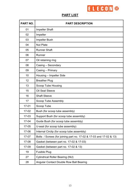
PART LIST<br />
PART NO. PART DESCRIPTION<br />
01 Impeller Shaft<br />
02 Impeller<br />
03 Impeller Bush<br />
04 Nut Plate<br />
05 Runner Shaft<br />
06 Runner<br />
07 Oil retaining ring<br />
08 Casing – Secondary<br />
09 Casing – Primary<br />
10 Housing – Impeller Side<br />
12 Breather Plug<br />
13 Scoop Tube Housing<br />
15 Oil Seal Sleeve<br />
16 Shaft Sleeve<br />
17 Scoop Tube Assembly<br />
17-01 Scoop Tube<br />
17-02 Bush (<strong>for</strong> <strong>scoop</strong> tube assembly)<br />
17-03 Support Bush (<strong>for</strong> <strong>scoop</strong> tube assembly)<br />
17-04 Guide Bush (<strong>for</strong> <strong>scoop</strong> tube assembly)<br />
17-05 U-seal (<strong>for</strong> <strong>scoop</strong> tube assembly)<br />
17-06 Internal Circlip (<strong>for</strong> <strong>scoop</strong> tube assembly)<br />
17-07 Bolts / Screws (<strong>for</strong> joining part no. 17-02 & 17-03 and 17-02 & 13)<br />
17-08 Gasket (between part no. 17-02 & 17-03)<br />
17-09 Gasket (between part no. 17-02 & 13)<br />
19 Fusible Plug<br />
27 Cylindrical Roller Bearing (NU)<br />
28 Angular Contact Double Row Ball Bearing<br />
13