Surface Sand Filters PTP-04 - City of Franklin
Surface Sand Filters PTP-04 - City of Franklin
Surface Sand Filters PTP-04 - City of Franklin

You also want an ePaper? Increase the reach of your titles
YUMPU automatically turns print PDFs into web optimized ePapers that Google loves.
General Application<br />
ACTIVITY: <strong>Surface</strong> <strong>Sand</strong> <strong>Filters</strong> <strong>PTP</strong>-<strong>04</strong><br />
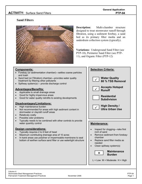
<strong>Sand</strong> <strong>Filters</strong><br />
Components:<br />
• Forebay (or sedimentation chamber)—settles coarse particles<br />
and trash<br />
• <strong>Sand</strong> bed (or Filtration) chamber—provides water quality<br />
treatment by filtering other pollutants<br />
• Spillway system(s)— provide discharge control<br />
Advantages/Benefits:<br />
• Applicable to small drainage areas<br />
• Good for highly impervious areas<br />
• Good for water quality retr<strong>of</strong>its to existing developments<br />
Disadvantages/Limitations:<br />
• High maintenance burden<br />
• Not recommended for areas with high sediment content in<br />
stormwater or clay/silt run<strong>of</strong>f areas<br />
• Relatively costly<br />
• Possible odor problems<br />
• Typically needs to be combined with other controls to provide<br />
water quantity control<br />
Design considerations:<br />
• Typically requires 2 to 6 feet <strong>of</strong> head<br />
• Maximum contributing drainage area <strong>of</strong> 10 acres<br />
• In karst areas use polyliner or impermeable membrane to seal<br />
bottom <strong>of</strong> earthen surface sand filter or use watertight structure<br />
Description: Multi-chamber structure<br />
designed to treat stormwater run<strong>of</strong>f through<br />
filtration, using a sediment forebay, a sand<br />
bed as its primary filter media and an<br />
underdrain collection system (typically).<br />
Variations: Underground <strong>Sand</strong> Filter (see<br />
<strong>PTP</strong>-10), Perimeter <strong>Sand</strong> Filter (see <strong>PTP</strong>-<br />
11), and Organic Filter (<strong>PTP</strong>-12)<br />
Selection Criteria:<br />
Maintenance:<br />
Water Quality<br />
80 % TSS Removal<br />
Accepts Hotspot<br />
Run<strong>of</strong>f<br />
Residential<br />
Subdivision<br />
High Density /<br />
Ultra Urban Use<br />
• Inspect for clogging—rake first<br />
inch <strong>of</strong> sand<br />
• Remove sediment from forebaychamber<br />
• Replace sand filter media as<br />
needed<br />
• Clean spillway system(s)<br />
Maintenance<br />
Burden<br />
L = Low M = Moderate H = High<br />
Volume 4:<br />
Stormwater Best Management Practices- <strong>PTP</strong>-<strong>04</strong><br />
Permanent Treatment Management Practices November 2006 Page 1<br />
<br />
<br />
<br />
H
General Application<br />
ACTIVITY: <strong>Surface</strong> <strong>Sand</strong> <strong>Filters</strong> <strong>PTP</strong>-<strong>04</strong><br />
General<br />
Description<br />
Site and Design<br />
Considerations<br />
<strong>Sand</strong> filters (also referred to as filtration basins) are structural stormwater<br />
controls that capture and temporarily store stormwater run<strong>of</strong>f and treat it by<br />
filtering it through a bed <strong>of</strong> sand. The surface sand filter is a ground-level<br />
open air structure that consists <strong>of</strong> a pretreatment sediment forebay and a<br />
sand bed chamber. This system can treat drainage areas up to 10 acres in<br />
size and is an <strong>of</strong>f-line device in which flows larger than the water quality<br />
volume by-pass the system. <strong>Surface</strong> sand filters can be designed as an<br />
excavation with earthen embankments or as a concrete or block structure.<br />
The filtered run<strong>of</strong>f is collected and returned to the conveyance system, or it<br />
can also be partially or fully exfiltrated into the surrounding soil in areas<br />
with porous soils. A schematic <strong>of</strong> a surface sand filter is shown in Figure<br />
4.1.<br />
Because they have few site constraints beside head requirements, sand<br />
filters can be used on development sites where the use <strong>of</strong> other structural<br />
controls may be precluded. However, sand filter systems can be relatively<br />
expensive to construct and install and they have high maintenance<br />
requirements.<br />
A design variant, the underground sand filter, is intended primarily for<br />
extremely space limited and high density areas and is thus considered a<br />
limited application structural control. See <strong>PTP</strong>-10 for more details.<br />
Another design variant is the perimeter sand filter, which is an enclosed<br />
filter system typically constructed just below grade in a vault along the edge<br />
<strong>of</strong> an impervious area such as a parking lot. See <strong>PTP</strong>-16 for information on<br />
the perimeter sand filter.<br />
In surface sand filter systems, stormwater pollutants are removed through a<br />
combination <strong>of</strong> gravitational settling, filtration, and adsorption. The<br />
filtration process effectively traps suspended solids and particulates. As<br />
solids are trapped in the sand bed, some reduction <strong>of</strong> associated pollutants<br />
such as biochemical oxygen demand (BOD), fecal coliform bacteria, and<br />
other pollutants may be achieved.<br />
Location and Siting<br />
1. <strong>Surface</strong> sand filters should have a contributing drainage area <strong>of</strong> 10 acres<br />
or less.<br />
2. <strong>Surface</strong> sand filter systems are generally applied to land uses with a<br />
high percentage <strong>of</strong> impervious surfaces. Sites with less than 50%<br />
imperviousness or with high clay/silt sediment loads must not use sand<br />
filters without adequate pretreatment because the sediment causes<br />
clogging and failure <strong>of</strong> the filter bed. Any disturbed areas within the<br />
sand filter facility drainage area should be identified and stabilized.<br />
Filtration controls should only be constructed after the construction site<br />
is stabilized.<br />
Volume 4:<br />
Stormwater Best Management Practices- <strong>PTP</strong>-<strong>04</strong><br />
Permanent Treatment Management Practices November 2006 Page 2
General Application<br />
ACTIVITY: <strong>Surface</strong> <strong>Sand</strong> <strong>Filters</strong> <strong>PTP</strong>-<strong>04</strong><br />
Site and Design<br />
Considerations<br />
(Continued)<br />
3. <strong>Surface</strong> sand filters are used in an <strong>of</strong>f-line configuration where the water<br />
quality volume (WQv) is diverted to the filter facility. Stormwater flows<br />
greater than the WQv are diverted to other controls or downstream using<br />
a diversion structure or flow splitter.<br />
4. <strong>Sand</strong> filter systems are designed for intermittent flow and must be<br />
allowed to drain and aerate between rainfall events. They should not be<br />
used on sites with a continuous flow from groundwater, sump pumps, or<br />
other sources.<br />
General Design<br />
5. A surface sand filter facility consists <strong>of</strong> a two-chamber open-air<br />
structure, which is located at ground-level. The first chamber is the<br />
sediment forebay (sedimentation chamber) while the second chamber<br />
houses the sand filter bed. Flow enters the forebay chamber where<br />
settling <strong>of</strong> larger sediment particles occurs. Discharge from the forebay<br />
chamber flows through a perforated standpipe into the sand bed<br />
chamber. The flow is then uniformly distributed across the sand bed<br />
chamber via distribution vault or weir. After passing though the filter<br />
bed, run<strong>of</strong>f is collected by a perforated pipe and gravel underdrain<br />
system. Figure 4.1 provides plan view and pr<strong>of</strong>ile schematics <strong>of</strong> a<br />
surface sand filter.<br />
Physical Specifications/Geometry<br />
6. The entire treatment system (including the forebay) must temporarily<br />
hold the WQv prior to filtration. Table 4.1 presents the design<br />
parameters and values for the perimeter sand filter. Figure 4.2 illustrates<br />
these design parameters.<br />
7. The forebay chamber must be sized to at least 50% <strong>of</strong> the computed<br />
WQv, hold this volume for 24 hours, and have a length-to-width ratio <strong>of</strong><br />
at least 2:1. Inlet and outlet structures should be located at opposite<br />
ends <strong>of</strong> the chamber.<br />
8. The filter area is sized based on the principles <strong>of</strong> Darcy’s Law. A<br />
coefficient <strong>of</strong> permeability (k) <strong>of</strong> 3.5 ft/day for sand should be used.<br />
The filter bed is typically designed to completely drain in 24 hours or<br />
fewer.<br />
9. The filter media consists <strong>of</strong> an 18 to 24 inch layer <strong>of</strong> clean washed<br />
medium sand (meeting ASTM C-33 concrete sand) on top <strong>of</strong> the<br />
underdrain system. Permeable filter fabric is placed both above and<br />
below the sand bed to prevent clogging <strong>of</strong> the sand filter and the<br />
underdrain system. Figure 4.3 illustrates a typical media cross section.<br />
10. The filter bed is equipped with a 6-inch perforated pipe (ASTM<br />
Schedule 40) underdrain in a gravel layer. The underdrain must have a<br />
minimum grade <strong>of</strong> 1/8-inch per foot (1% slope). Holes should be 3/8-<br />
inch diameter and spaced approximately 6 inches on center. Gravel<br />
should be clean washed aggregate with a maximum diameter <strong>of</strong> 3.5<br />
Volume 4:<br />
Stormwater Best Management Practices- <strong>PTP</strong>-<strong>04</strong><br />
Permanent Treatment Management Practices November 2006 Page 3
General Application<br />
ACTIVITY: <strong>Surface</strong> <strong>Sand</strong> <strong>Filters</strong> <strong>PTP</strong>-<strong>04</strong><br />
Site and Design<br />
Considerations<br />
(Continued)<br />
inches and a minimum diameter <strong>of</strong> 1.5 inches with a void space <strong>of</strong> about<br />
30%. Do not use aggregate contaminated with soil.<br />
11. The structure <strong>of</strong> the surface sand filter may be constructed <strong>of</strong><br />
impermeable media such as concrete, or through the use <strong>of</strong> excavations<br />
and earthen embankments. When constructed with earthen<br />
walls/embankments, filter fabric should be used to line the bottom and<br />
side slopes <strong>of</strong> the structures before installation <strong>of</strong> the underdrain system<br />
and filter media. The structure should include an access ramp at 4:1<br />
(H:V) or less for maintenance.<br />
Table 4.1 <strong>Surface</strong> <strong>Sand</strong> Filter Design Parameters<br />
Parameter Description Parameter Parameter Value<br />
Total Temporary Volume in<br />
Forebay and <strong>Sand</strong> Bed<br />
Chamber<br />
WQv WQv; See Design Step #1<br />
Approximate Temporary <strong>Sand</strong><br />
Bed Volume 1<br />
VST (0.5) WQv<br />
Minimum <strong>Sand</strong> Bed<br />
Thickness<br />
TS 18 inches<br />
<strong>Sand</strong> Bed Design Porosity n 0.3<br />
<strong>Sand</strong> Bed Design<br />
Permeability<br />
k 3.5 feet/day<br />
<strong>Sand</strong> Bed Design Drain Time td 1.5 days, 36 hours max<br />
Minimum <strong>Sand</strong> Bed Chamber<br />
Area<br />
AS See Design Step #6<br />
Approximate Temporary<br />
Forebay Volume 2<br />
VFT (0.5) WQv<br />
Minimum Forebay <strong>Surface</strong><br />
Area<br />
AF (0.05) WQv<br />
Maximum Temporary <strong>Sand</strong><br />
Bed Depth 3<br />
DST See Design Step #3<br />
Minimum Temporary Forebay<br />
Depth<br />
DFT 2 feet<br />
Overall Minimum Length to<br />
Width Ratio<br />
L/W 2<br />
1. Includes temporary storage volume in sand.<br />
2. Includes temporary storage volume in sand.<br />
3. Excludes storage volume in forebay permanent pool.<br />
4. Measured from top <strong>of</strong> sand bed.<br />
(Adapted from the New Jersey Stormwater Best Management Practices<br />
Manual)<br />
Volume 4:<br />
Stormwater Best Management Practices- <strong>PTP</strong>-<strong>04</strong><br />
Permanent Treatment Management Practices November 2006 Page 4
General Application<br />
ACTIVITY: <strong>Surface</strong> <strong>Sand</strong> <strong>Filters</strong> <strong>PTP</strong>-<strong>04</strong><br />
Site and Design<br />
Considerations<br />
(Continued)<br />
Pretreatment/Inlets<br />
12. Pretreatment <strong>of</strong> run<strong>of</strong>f in a sand filter system is provided by the forebay<br />
chamber.<br />
13. Inlets to surface sand filters are to be provided with energy dissipaters.<br />
Exit velocities from the forebay chamber must be nonerosive.<br />
14. Figure 4.4 shows a typical inlet pipe from the forebay to the sand bed<br />
chamber where the flow is then evenly distributed across the filtration<br />
area.<br />
Outlet Structures<br />
Outlet pipe is to be provided from the underdrain system to the facility<br />
discharge. Due to the slow rate <strong>of</strong> filtration, outlet protection is generally<br />
unnecessary (except for emergency overflows and spillways).<br />
Emergency Spillway<br />
<strong>Surface</strong> sand filters are <strong>of</strong>f-line devices and the emergency spillway is<br />
provided in case diversion structure fails. The spillway prevents filter water<br />
levels from overtopping the embankment and causing structural damage.<br />
The emergency spillway should be located so that downstream buildings<br />
and structures will not be impacted by spillway discharges.<br />
Maintenance Access<br />
Adequate access through maintenance easements must be provided for all<br />
sand filter systems for inspection and maintenance, including the<br />
appropriate equipment and vehicles. Facility designs must enable<br />
maintenance personnel to easily replace the upper layers <strong>of</strong> the filter media.<br />
Maintenance access ramps at a 4:1 slope or flatter must be provided.<br />
Safety Features<br />
<strong>Surface</strong> sand filter facilities can be fenced to prevent unauthorized access.<br />
Volume 4:<br />
Stormwater Best Management Practices- <strong>PTP</strong>-<strong>04</strong><br />
Permanent Treatment Management Practices November 2006 Page 5
General Application<br />
ACTIVITY: <strong>Surface</strong> <strong>Sand</strong> <strong>Filters</strong> <strong>PTP</strong>-<strong>04</strong><br />
Design<br />
Procedures<br />
Step 1. Compute the Water Quality Volume.<br />
Calculate the Water Quality Volume (WQv), which must be temporarily stored<br />
within the perimeter sand filter’s entire treatment system.<br />
WQv = P x Rv x A/12<br />
Where:<br />
WQv = water quality treatment volume, ac-ft<br />
P = rainfall for the 85% storm event (1.1 in)<br />
Rv = run<strong>of</strong>f coefficient (see below)<br />
A = site area, acres<br />
Rv = 0.015 + 0.0092*I<br />
Where:<br />
I = site impervious cover, % (for example 50% equals 50)<br />
Step 2. Determine approximate required volumes <strong>of</strong> the forebay and sand bed.<br />
Each should be equal to approximately 0.5 WQv, as shown in Table 4.1.<br />
Step 3. Determine approximate temporary depths in sand bed (DST) and forebay<br />
(DFT) for the WQv.<br />
The estimate will depend on and be based on analysis <strong>of</strong> site conditions including<br />
the difference between the invert elevation <strong>of</strong> the downstream conveyance system<br />
and the maximum ground elevation at filter facility. Make sure to include the<br />
minimum sand bed thickness (THS) into the consideration for these temporary<br />
depths. Note that the maximum temporary depth in the sand bed zone (DST) is<br />
measured from the top <strong>of</strong> the sand bed, while the maximum temporary forebay<br />
depth (DFT) is measured the bottom <strong>of</strong> the forebay.<br />
Step 4. Compute minimum forebay surface area (AF).<br />
The minimum surface area is<br />
AF = 0.05 (WQv)<br />
Where:<br />
AF = forebay area<br />
0.05 = a multiplier in units per area <strong>of</strong> volume (L 2 /L 3 )<br />
Volume 4:<br />
Stormwater Best Management Practices- <strong>PTP</strong>-<strong>04</strong><br />
Permanent Treatment Management Practices November 2006 Page 6
General Application<br />
ACTIVITY: <strong>Surface</strong> <strong>Sand</strong> <strong>Filters</strong> <strong>PTP</strong>-<strong>04</strong><br />
Design<br />
Procedures<br />
Continued<br />
Step 5. Compute total temporary storage volume in the forebay (VFT).<br />
From the maximum temporary depth in the forebay (DFT) from Step 3 and the<br />
minimum forebay area (AF) from Step 4, compute the total temporary storage<br />
volume in the forebay (VFT). Compare this volume with the approximate<br />
required forebay volume computed in Step 2. Adjust the maximum temporary<br />
forebay depth (DFT) and/or forebay area (AF) as necessary to achieve a total<br />
temporary forebay storage volume (VFT) as close as practical to the required<br />
forebay volume from Step 2. While adjusting the forebay surface area (AF) by<br />
varying its length and width, remember that the forebay will be located<br />
immediately adjacent to the sand bed zone and that the minimum overall length<br />
to width ratio <strong>of</strong> the combined zone is two to one.<br />
Step 6. Compute sand bed chamber area (AS).<br />
The filter area is sized using the following equation (based on Darcy’s Law):<br />
Where:<br />
AS = (WQv) (TS / [(k) (DST/2 + TS) (TD)]<br />
AS = <strong>Sand</strong> Bed <strong>Surface</strong> Area (in square feet)<br />
TS = Thickness <strong>of</strong> <strong>Sand</strong> in <strong>Sand</strong> Bed<br />
(typically 18 inches, no more than 24 inches)<br />
k = Coefficient <strong>of</strong> permeability <strong>of</strong> filter media (ft/day)<br />
(use 3.5 ft/day for sand)<br />
DST = Maximum Temporary <strong>Sand</strong> Bed Depth (ft)<br />
td = <strong>Sand</strong> Bed Design Drain Time<br />
(1.5 days or 36 hours is recommended<br />
maximum)<br />
See the Physical Specifications/Geometry section <strong>of</strong> the Site and Design<br />
Considerations for filter media specifications.<br />
Step 7. Compute total temporary storage volume in sand bed.<br />
VST = (AS)(DST) + (AS)( TS)(n)<br />
Where:<br />
VST = Temporary <strong>Sand</strong> Bed Storage Volume (in cubic feet)<br />
AS = <strong>Sand</strong> Bed <strong>Surface</strong> Area (in square feet)<br />
DST = Maximum Temporary <strong>Sand</strong> Bed Depth (ft)<br />
TS = Thickness <strong>of</strong> <strong>Sand</strong> in <strong>Sand</strong> Bed, recommended 18 inches (in feet)<br />
n = <strong>Sand</strong> Bed Design Porosity, recommended 0.3<br />
Volume 4:<br />
Stormwater Best Management Practices- <strong>PTP</strong>-<strong>04</strong><br />
Permanent Treatment Management Practices November 2006 Page 7
General Application<br />
ACTIVITY: <strong>Surface</strong> <strong>Sand</strong> <strong>Filters</strong> <strong>PTP</strong>-<strong>04</strong><br />
Design<br />
Procedures<br />
(Continued)<br />
Step 8. Compare and adjust areas and volumes to achieve storage <strong>of</strong> WQv<br />
within the entire facility.<br />
Compare the total temporary sand bed storage volume (VST) with the<br />
approximate required sand bed zone volume computed in Step 2. As shown on<br />
Table 16.1, this temporary sand bed storage volume should be approximately<br />
one half <strong>of</strong> the stormwater quality design storm run<strong>of</strong>f volume (WQv). In<br />
addition, add the total temporary sand bed volume (VST) to the total temporary<br />
forebay storage volume (VFT) to determine the total temporary storage volume in<br />
the sand filter. As shown in Table 16.1, this total temporary storage volume must<br />
equal the stormwater quality design storm run<strong>of</strong>f volume (WQv). Adjust the<br />
maximum temporary sand bed depth (DST) and/or sand bed area (AS) as<br />
necessary to achieve a total temporary sand bed storage volume (VST) as close as<br />
practical to the required sand bed volume from Step 2 and a total filter volume<br />
equal to WQv. Remember, while adjusting width and length that forebay will be<br />
located immediately adjacent to the sand bed zone and that the minimum overall<br />
length to width ratio <strong>of</strong> the combined zone is two to one.<br />
Step 9. Design flow diversion structure.<br />
A flow regulator (or flow splitter diversion structure) should be supplied to divert<br />
the WQv to the sand filter.<br />
Size low flow orifice, weir, or other device to bypass the 100-year flood.<br />
Step 10. Design inlets, underdrain system, overflow wiers, and outlet structures.<br />
See Site and Design Considerations for more information on underdrain<br />
specifications and outlet structures. <strong>PTP</strong>-01 provides more information on sizing<br />
orifices, weirs, and outlets.<br />
Step 11. Design emergency overflow.<br />
An overflow must be provided in case <strong>of</strong> a failure in the diversion structure.<br />
Non-erosive velocities need to be ensured at the outlet point.<br />
Volume 4:<br />
Stormwater Best Management Practices- <strong>PTP</strong>-<strong>04</strong><br />
Permanent Treatment Management Practices November 2006 Page 8
General Application<br />
ACTIVITY: <strong>Surface</strong> <strong>Sand</strong> <strong>Filters</strong> <strong>PTP</strong>-<strong>04</strong><br />
(Source: New Jersey Stormwater Best Management Practices Manual, 2003)<br />
Figure 4.1 <strong>Surface</strong> <strong>Sand</strong> Filter Schematic<br />
Volume 4:<br />
Stormwater Best Management Practices- <strong>PTP</strong>-<strong>04</strong><br />
Permanent Treatment Management Practices November 2006 Page 9
General Application<br />
ACTIVITY: <strong>Surface</strong> <strong>Sand</strong> <strong>Filters</strong> <strong>PTP</strong>-<strong>04</strong><br />
(Source: New Jersey Stormwater Best Management Practices Manual, 2003)<br />
Figure 4.2 Schematic <strong>of</strong> <strong>Surface</strong> <strong>Sand</strong> Filter Showing Design Parameters<br />
Volume 4:<br />
Stormwater Best Management Practices- <strong>PTP</strong>-<strong>04</strong><br />
Permanent Treatment Management Practices November 2006 Page 10
General Application<br />
ACTIVITY: <strong>Surface</strong> <strong>Sand</strong> <strong>Filters</strong> <strong>PTP</strong>-<strong>04</strong><br />
(Source: Claytor and Schueler, 1996)<br />
Figure 4.3 Typical <strong>Sand</strong> Filter Media Cross Sections<br />
Volume 4:<br />
Stormwater Best Management Practices- <strong>PTP</strong>-<strong>04</strong><br />
Permanent Treatment Management Practices November 2006 Page 11
General Application<br />
ACTIVITY: <strong>Surface</strong> <strong>Sand</strong> <strong>Filters</strong> <strong>PTP</strong>-<strong>04</strong><br />
(Source: Claytor and Schueler, 1996)<br />
Figure 4.4 <strong>Surface</strong> <strong>Sand</strong> Filter Perforated Stand-Pipe<br />
Volume 4:<br />
Stormwater Best Management Practices- <strong>PTP</strong>-<strong>04</strong><br />
Permanent Treatment Management Practices November 2006 Page 12
General Application<br />
ACTIVITY: <strong>Surface</strong> <strong>Sand</strong> <strong>Filters</strong> <strong>PTP</strong>-<strong>04</strong><br />
References<br />
ARC, 2001. Georgia Stormwater Management Manual Volume 2 Technical Handbook.<br />
Connecticut Department <strong>of</strong> Environmental Protection, 20<strong>04</strong>. Stormwater Quality Manual.<br />
Center for Watershed Protection, Accessed July 2005. Stormwater Manager’s Resource Center.<br />
Manual Builder. www.stormwatercenter.net.<br />
New Jersey Department <strong>of</strong> Environmental Protection, 20<strong>04</strong>. Stormwater Best Management<br />
Practices Manual.<br />
StormwaterAuthority.com, Accessed January, 2006. “<strong>Sand</strong> and Organic <strong>Filters</strong>.”<br />
www.stormwaterauthority.com .<br />
Suggested Reading<br />
California Storm Water Quality Task Force, 1993. California Storm Water Best Management<br />
Practice Handbooks.<br />
<strong>City</strong> <strong>of</strong> Austin, TX, 1988. Water Quality Management. Environmental Criteria Manual.<br />
Environmental and Conservation Services.<br />
<strong>City</strong> <strong>of</strong> Sacramento, CA, 2000. Guidance Manual for On-Site Stormwater Quality Control<br />
Measures. Department <strong>of</strong> Utilities<br />
Claytor, R.A., and T.R. Schueler. 1996. Design <strong>of</strong> Stormwater Filtering Systems. The Center for<br />
Watershed Protection, Silver Spring, MD.<br />
Maryland Department <strong>of</strong> the Environment, 2000. Maryland Stormwater Design Manual,<br />
Volumes I and II. Prepared by Center for Watershed Protection (CWP).<br />
Metropolitan Washington Council <strong>of</strong> Governments (MWCOG), March, 1992, “A Current<br />
Assessment <strong>of</strong> Urban Best Management Practices: Techniques for Reducing Nonpoint Source<br />
Pollution in the Coastal Zone”.<br />
Northern Virginia Regional Commission (NVRC), 1992. The Northern Virginia BMP<br />
Handbook. Annandale, VA.<br />
US EPA, 1999. Storm Water Technology Fact Sheet: <strong>Sand</strong> <strong>Filters</strong>. EPA 832-F-99-007. Office<br />
<strong>of</strong> Water.<br />
Volume 4:<br />
Stormwater Best Management Practices- <strong>PTP</strong>-<strong>04</strong><br />
Permanent Treatment Management Practices November 2006 Page 13