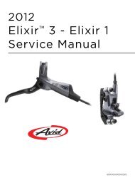
2012 Elixir 9 - Elixir 7 Service Manual - Sport Import GmbH
2012 Elixir 9 - Elixir 7 Service Manual - Sport Import GmbH
2012 Elixir 9 - Elixir 7 Service Manual - Sport Import GmbH

You also want an ePaper? Increase the reach of your titles
YUMPU automatically turns print PDFs into web optimized ePapers that Google loves.
<strong>2012</strong><br />
<strong>Elixir</strong> 9 - <strong>Elixir</strong> 7<br />
<strong>Service</strong> <strong>Manual</strong><br />
GEN.0000000003393
2<br />
SRAM LLC WARRANTY<br />
SRAM warrants its products to be free from defects in materials or workmanship for a period of two<br />
years after original purchase. This warranty only applies to the original owner and is not transferable.<br />
Claims under this warranty must be made through the retailer where the bicycle or the SRAM<br />
component was purchased. Original proof of purchase is required.<br />
This warranty statement gives the customer specific legal rights. The customer may also have other<br />
rights which vary from state to state (USA), from province to province (Canada), and from country to<br />
country elsewhere in the world.<br />
To the extent that this warranty statement is inconsistent with the local law, this warranty shall be<br />
deemed modified to be consistent with such law, under such local law, certain disclaimers and<br />
limitations of this warranty statement may apply to the customer. For example, some states in the<br />
United States of America, as well as some governments outside of the United States (including<br />
provinces in Canada) may:<br />
a. Preclude the disclaimers and limitations of this warranty statement from limiting the statutory rights of<br />
the consumer (e.g. United Kingdom).<br />
b. Otherwise restrict the ability of a manufacturer to enforce such disclaimers or limitations.<br />
To the extent allowed by local law, except for the obligations specifically set forth in this warranty<br />
statement, in no event shall SRAM or its third-party suppliers be liable for direct, indirect, special,<br />
incidental, or consequential damages.<br />
· This warranty does not apply to products that have been incorrectly installed and/or adjusted<br />
according to the respective SRAM technical installation manual. The SRAM installation manuals can be<br />
found online at www.sram.com, www.rockshox.com, www.avidbike.com, www. truvativ.com, or<br />
www.zipp.com.<br />
· This warranty does not apply when the product has been modified.<br />
· This warranty does not apply when the serial number or production code has been deliberately altered,<br />
defaced or removed.<br />
· This warranty does not apply to damage to the product caused by a crash, impact, abuse of the product,<br />
non-compliance with manufacturer’s specifications of usage or any other circumstances in which the<br />
product has been subjected to forces or loads beyond its design.<br />
· This warranty does not apply to normal wear and tear. Wear and tear parts are subject to damage as a<br />
result of normal use, failure to service according to SRAM recommendations and/or riding or installation<br />
in conditions or applications other than recommended.<br />
Wear and tear parts are identified as:<br />
Dust seals/Bushings/Air sealing o-rings/Glide rings/Rubber moving parts/Foam rings/Rear shock<br />
mounting hardware and main seals/Stripped threads and bolts (aluminum,titanium, magnesium or steel)/<br />
Upper tubes (stanchions)/Brake sleeves/Brake pads/Chains/Sprockets/Cassettes/Shifter and brake<br />
cables (inner and outer)/Handlebar grips/Shifter grips/Jockey wheels/Disc brake rotors/Wheel braking<br />
surfaces/Bottom out pads/Bearings/Bearing Races/Pawls/Transmission gears/Spokes/Free hubs/<br />
Aero bar pads/Corrosion/Tools<br />
· This warranty shall not cover damages caused by the use of parts of different manufacturers.<br />
· This warranty shall not cover damages caused by the use of parts that are not compatible, suitable and/<br />
or authorized by SRAM for use with SRAM components.<br />
· This warranty shall not cover damages resulting from commercial (rental) use.<br />
AVID BRAKE SERVICE<br />
We recommend that you have your Avid brakes serviced by a qualified bicycle mechanic. Servicing Avid<br />
brakes requires knowledge of brake components as well as the special tools and fluids used for service.<br />
This publication includes trademarks and registered trademarks of SRAM Corporation designated by the symbols and ®, respectively.<br />
Copyright © SRAM LLC 2011<br />
For exploded diagram and part number information, please refer to the Spare Parts Catalog available on our web site at www.sram.com.<br />
For order information, please contact your local SRAM distributor or dealer.<br />
Information contained in this publication is subject to change at any time without prior notice. For the latest technical information, please visit our website at www.sram.com.<br />
Your product‘s appearance may differ from the pictures/diagrams contained in this catalog.<br />
Product names used in this document may be trademarks or registered trademarks of others.
3<br />
TABLE OF CONTENTS<br />
ELIXIR 9 & 7 BRAKE LEVER OVERHAUL ................................................................................................................................ 5<br />
PARTS AND TOOLS NEEDED FOR SERVICE: ................................................................................................................................................................. 5<br />
ELIXIR 9 & 7 BRAKE CALIPER OVERHAUL .......................................................................................................................... 14<br />
PARTS AND TOOLS NEEDED FOR SERVICE: ................................................................................................................................................................14<br />
AVID BRAKE HOSE LENGTH ADJUSTMENT ........................................................................................................................20<br />
PARTS AND TOOLS NEEDED FOR SERVICE: .............................................................................................................................................................. 20<br />
AVID BRAKE BLEED PROCEDURE ........................................................................................................................................24<br />
PARTS AND TOOLS NEEDED FOR SERVICE: ...............................................................................................................................................................24<br />
DISC BRAKE PAD INSTALLATION INSTRUCTIONS ............................................................................................................30<br />
DISC BRAKE PAD AND ROTOR BED-IN PROCEDURE ........................................................................................................31
SAFETY FIRST!<br />
At SRAM, we care about YOU. Please, always wear your safety<br />
glasses and protective gloves when servicing your<br />
componentry.<br />
Protect yourself! Wear your safety gear!<br />
<strong>Import</strong>ant: Your parts may look different from those illustrated.
5<br />
ELIXIR 9 & 7 BRAKE LEVER OVERHAUL<br />
Avid brake lever assemblies need to be serviced periodically to optimize braking function. If brake fluid is leaking from any area<br />
of the brake lever assembly, there may be damage or wear and tear to the internal moving parts. If your brake was filled with fluid<br />
OTHER than DOT 5.1 or 4 (such as mineral oil or DOT 5), damage to all rubber and plastic internal parts may exist. If your brake was<br />
damaged in a crash, there may be damage to the lever blade and pushrod assemblies, as well as the housing assembly. Inspection<br />
and/or replacement of these parts, due to any of the above situations, will be necessary to restore proper brake function.<br />
WARNING:<br />
• Avid highly recommends the use of nitrile gloves when handling DOT fluids.<br />
• DOT FLUIDS WILL DAMAGE PAINTED SURFACES! If any fluid comes in contact with a painted surface (i.e. your frame) or<br />
printing on the brakes, wipe it off immediately and clean with isopropyl alcohol or water. REMOVAL OF PAINT AND/OR<br />
PRINTING BY DOT FLUID IS NOT COVERED UNDER WARRANTY!<br />
• Do not allow any brake fluid to come in contact with the brake pads. If this occurs, the pads are contaminated and must be<br />
replaced.<br />
• For best results, use only Avid High-Performance 5.1 DOT Fluid. If Avid fluid is not available, only use DOT 5.1 or 4 fluid. Do<br />
NOT use mineral oil or DOT 5 fluid.<br />
• Used DOT fluid should be recycled or disposed of in accordance to local and federal regulations.<br />
• NEVER pour DOT fluid down a sewage or drainage system or into the ground or a body of water.<br />
PARTS AND TOOLS NEEDED FOR SERVICE:<br />
• Safety glasses<br />
• Nitrile gloves<br />
• T25 TORX®<br />
• <strong>Elixir</strong> Lever Pivot Bearing Press Tool<br />
• Oil pan<br />
• Avid High-Performance 5.1 DOT Fluid or DOT 4 Fluid, or Avid<br />
DOT Grease or DOT 5.1 or 4 compatible grease<br />
• Adjustable torque wrench<br />
• 8 mm flare nut wrench<br />
• 11 mm open end wrench<br />
• 2 and 5 mm hex wrenches<br />
• Bench vise or 10 mm open end wrench<br />
• Soapy water<br />
• Clean, lint-free rag<br />
<strong>Elixir</strong> 9 & 7 brakE lEvEr ovErhaul
6<br />
EXPLODED VIEW - ELIXIR 9 BRAKE LEVER ASSEMBLY<br />
A B C<br />
G<br />
A. LEVER BODY E. PIVOT CLIP I. PUSHROD SLEEVE<br />
B. PIVOT BUSHINGS F. LEVER BLADE J. REACH ADJUST KNOB<br />
C. PISTON/BLADDER/PUSHROD ASSEMBLY G. PISTON SPRING<br />
D. PIVOT PIN H. SNAP RING<br />
(SHOWN REMOVED)<br />
1<br />
Use a T25 TORX® to remove the brake clamp bolt from the<br />
discrete clamp, MMX, or XLoc (XLoc will first require the<br />
removal of the XX shifter). Remove the brake lever from the<br />
handlebar. Pull the hose boot off the compression nut and slide<br />
it down the hose.<br />
If dirty, clean the levers with soapy water and a clean rag.<br />
H<br />
D<br />
I<br />
E<br />
T25 MMX<br />
J<br />
F<br />
<strong>Elixir</strong> 9 & 7 brakE lEvEr ovErhaul
7<br />
2<br />
3<br />
4<br />
Use an 11 mm open end wrench to hold the hose stop in place<br />
and use an 8 mm flare nut wrench to unthread the hose<br />
compression nut. Pull the brake hose and compression fitting<br />
from the brake lever body.<br />
Allow any brake fluid to drain into a container. Hold the lever<br />
assembly over the container and squeeze the lever to pump<br />
any brake fluid from inside the lever assembly.<br />
If the system has been contaminated with the wrong fluid,<br />
you will need to flush all the parts with soapy water, rinse,<br />
and allow to dry prior to rebuilding. You will also need to<br />
install all new seals and a new hose.<br />
Remove the pivot pin.<br />
Carbon lever blade: Use the <strong>Elixir</strong> Lever Pivot Bearing<br />
Press Tool to remove the pivot pin from the lever:<br />
Prepare the tool by first installing the small washer<br />
followed by the press sleeve onto the bolt.<br />
Next, slide the bolt through pivot pin of the lever.<br />
Thread the catcher onto the bolt until it<br />
makes contact with the lever body.<br />
Insert the lever blade brace, with the contoured<br />
side against the pivot pin, into the lever blade.<br />
Use a vise or 10 mm open end wrench to hold<br />
the flat end section of the catcher.<br />
<strong>Elixir</strong> 9 & 7 brakE lEvEr ovErhaul
8<br />
5<br />
Use a 5 mm hex to turn the bolt clockwise until<br />
the pivot pin is pushed into the catcher.<br />
Remove the tool and pin from the brake lever.<br />
The pivot bushings, pivot clip, and dowel may fall out of<br />
the lever blade, this is ok. Set them aside on a clean rag.<br />
Aluminum lever blade:<br />
<strong>Elixir</strong> 9 only - First, depress the lever blade and<br />
use a 2 mm hex to remove the set screw.<br />
<strong>Elixir</strong> 9 & 7 - Open a vise 1/2 inch and place<br />
a clean rag over the jaws of the vise.<br />
Position the pivot pin over the opening of the vise. Use a<br />
rubber mallet to gently tap a 5 mm hex against the pivot pin.<br />
Remove the hex and pivot pin from the brake lever.<br />
Turn the reach adjust knob counter-clockwise by hand to<br />
remove the lever from the pushrod.<br />
5 mm<br />
2 mm<br />
5 mm<br />
<strong>Elixir</strong> 9 & 7 brakE lEvEr ovErhaul
9<br />
6<br />
7<br />
To replace a damaged or lost reach adjust knob assembly:<br />
Clamp a 4 mm hex into a vise with the long end extending<br />
upward. Install the end of the sleeve onto the 4 mm hex.<br />
Use a 2.5 mm hex to remove the reach stop screw, then remove<br />
the reach knob, spring, cross dowel, and blade from the sleeve.<br />
Install the new cross dowel into the lever blade and slide<br />
the sleeve through the recessed side of the dowel.<br />
Slide the new reach knob, followed by the spring, onto<br />
the sleeve. Clamp a 4 mm hex into a vise with the long<br />
end extending upward. Install the end of the sleeve onto<br />
the 4 mm hex. Use a 2.5 mm hex to install and tighten<br />
the reach stop screw to 0.5-0.7 N·m (4-6 in-lb). Remove<br />
the reach adjust/blade assembly from the 4 mm hex.<br />
Clamp a 2 mm hex into a vise with the long end extending<br />
upward. Install the lever body onto the wrench, with the<br />
wrench inserted into the lever body through the fluid flow port<br />
in the master cylinder head.<br />
Place a clean rag under the lever body to<br />
wipe up any fluid that may spill out.<br />
4 mm 2.5 mm<br />
2 mm<br />
4 mm 2.5 mm<br />
<strong>Elixir</strong> 9 & 7 brakE lEvEr ovErhaul
10<br />
8<br />
9<br />
Use long snap ring pliers to collapse the snap ring. Then apply<br />
downward pressure to the lever body and use the pliers to<br />
remove the snap ring in the lever body along with the piston/<br />
bladder assembly. Remove the lever body from the hex<br />
wrench.<br />
The piston/bladder assembly is attached to the snap ring.<br />
CAUTION<br />
Caution: Do not look directly into the lever body while<br />
performing this step. The internal piston/spring assembly<br />
is preloaded and will come out of the lever body quickly.<br />
Replace the entire piston/bladder/snap ring assembly with a<br />
new assembly. Lubricate the piston/bladder assembly by<br />
dipping it into Avid High-Performance 5.1 DOT Fluid.<br />
You can also use Avid DOT Grease, or DOT 5.1<br />
or 4 compatible grease, as a lubricant.<br />
10 Position the snap ring on the retainer of the piston, with the<br />
clocked portion of the retainer seated between the two<br />
centering tabs of the snap ring.<br />
<strong>Elixir</strong> 9 & 7 brakE lEvEr ovErhaul
11<br />
11<br />
Use long snap ring pliers to push the piston/bladder/snap ring<br />
assembly into the lever body, and secure the snap ring in its<br />
groove.<br />
Orient the snap ring eyelets toward the lever blade opening.<br />
You can also a long 10 mm socket against the snap ring to push<br />
the piston/bladder/snap ring assembly into the lever body.<br />
If you push the snap ring past its groove, you can use the<br />
2 mm hex in the vise to push the assembly into position<br />
from inside the fluid flow port of the lever body<br />
12 Aluminum <strong>Elixir</strong> 7 lever blade only - Insert a pivot bushing<br />
between each side of the lever body.<br />
13<br />
Align the pushrod sleeve and the pushrod. Turn the reach<br />
knob clockwise by hand onto the pushrod.<br />
<strong>Elixir</strong> 9 & 7 brakE lEvEr ovErhaul
12<br />
14 Re-install the pivot pin.<br />
Carbon lever blade:<br />
Slide a pivot bushing in between each side of the lever blade<br />
and the lever body, with the convex side of the bushings<br />
facing out. Insert the pivot clip inside the lever blade.<br />
Align the holes of the lever body, both washers, the pivot<br />
clip, and the lever blade, then slide the press sleeve of<br />
the press tool into the holes to maintain alignment<br />
Use the press tool to install the pivot pin into the lever:<br />
Prepare the tool by installing the washer and<br />
brake lever pivot pin onto the bolt.<br />
Insert the threaded end of the bolt through<br />
the press sleeve in the lever body.<br />
Thread the catcher, open end first, onto the bolt<br />
from the other side of the lever body.<br />
Use a vise or 10 mm open end wrench to hold<br />
the flat end section of the catcher.<br />
Insert the lever blade brace into the lever blade with<br />
the contoured end resting against the press sleeve.<br />
Use a 5 mm hex to turn the bolt clockwise and press the<br />
press sleeve and pivot pin into the lever body until the press<br />
sleeve separates from the lever body and drops into the<br />
catcher and the pivot pin is centered in the lever body.<br />
Remove the tool from the brake lever.<br />
The lever blade action may feel sluggish following<br />
installation of the pivot pin. To improve the feel, mount<br />
the brake lever onto the handlebar, hold the lever blade<br />
between your thumb and forefinger, then gently flex the<br />
lever blade from side to side. Check the lever pivot action.<br />
Repeat this process until the lever pivot action feels<br />
smooth. Be careful not to flex the lever too far at any time,<br />
otherwise damage to the lever blade or body could occur.<br />
5 mm<br />
5 mm<br />
<strong>Elixir</strong> 9 & 7 brakE lEvEr ovErhaul
13<br />
Aluminum lever blade:<br />
<strong>Elixir</strong> 9 & 7 - Confirm that the pivot bushings are still in<br />
place. Insert the pivot clip into lever blade and align it<br />
with the holes in the lever body and lever blade. Align<br />
the holes in the lever body, both bushings and the<br />
lever blade. Gently tap the pivot pin into place with a<br />
rubber mallet until it is flush with the lever body.<br />
<strong>Elixir</strong> 9 only - Depress the lever and use a 2 mm hex to<br />
re-install and tighten the pivot set screw<br />
to 1.1-1.3 N·m (10-11 in-lb).<br />
The lever blade action may feel sluggish following<br />
installation of the pivot pin. To improve the feel, mount<br />
the brake lever onto the handlebar, hold the lever blade<br />
between your thumb and forefinger, then gently flex the<br />
lever blade from side to side. Check the lever pivot action.<br />
Repeat this process until the lever pivot action feels<br />
smooth. Be careful not to flex the lever too far at any time,<br />
otherwise damage to the lever blade or body could occur.<br />
15 Use an 11 mm open end wrench to hold the hose stop in place<br />
and use an 8 mm flare nut wrench to thread the hose<br />
compression nut onto the lever body. Slide the hose boot onto<br />
the compression nut.<br />
Re-install the brake lever into the discrete clamp,<br />
MMX, or XLoc. Use a T25 TORX® to re-install the brake<br />
clamp bolt into the discreet clamp, MMX, or XLoc.<br />
8 mm 11 mm<br />
T25 MMX<br />
2 mm<br />
<strong>Elixir</strong> 9 & 7 brakE lEvEr ovErhaul
14<br />
ELIXIR 9 & 7 BRAKE CALIPER OVERHAUL<br />
Avid brake lever assemblies need to be serviced periodically in order to optimize braking function. If brake fluid is leaking<br />
from any area of the brake lever assembly, there may be damage or wear and tear to the internal moving parts. If your brake<br />
was filled with fluid OTHER than DOT 5.1 or 4 (such as mineral oil or DOT 5), damage to all rubber and plastic internal parts<br />
may exist. If your brake was damaged in a crash, there may be damage to the lever blade and pushrod assemblies, as well as<br />
the housing assembly. Inspection and/or replacement of these parts, due to any of the above situations, will be necessary to<br />
restore proper brake function.<br />
WARNING:<br />
• Avid highly recommends the use of nitrile gloves when handling DOT fluids.<br />
• DOT FLUIDS WILL DAMAGE PAINTED SURFACES! If any fluid comes in contact with a painted surface (i.e. your frame) or<br />
printing on the brakes, wipe it off immediately and clean with isopropyl alcohol or water. REMOVAL OF PAINT AND/OR<br />
PRINTING BY DOT FLUID IS NOT COVERED UNDER WARRANTY!<br />
• Do not allow any brake fluid to come in contact with the brake pads. If this occurs, the pads are contaminated and must be<br />
replaced.<br />
• For best results, use only Avid High-Performance 5.1 DOT Fluid. If Avid fluid is not available, only use DOT 5.1 or 4 fluid. Do<br />
NOT use mineral oil or DOT 5 fluid.<br />
• Used DOT fluid should be recycled or disposed of in accordance to local and federal regulations.<br />
• NEVER pour DOT fluid down a sewage or drainage system or into the ground or a body of water.<br />
PARTS AND TOOLS NEEDED FOR SERVICE:<br />
• Safety glasses<br />
• Nitrile gloves<br />
• T25 and T10 TORX® wrenches<br />
• Avid High-Performance 5.1 DOT Fluid or DOT 4 Fluid, or Avid<br />
DOT Grease or DOT 5.1 or 4 compatible grease<br />
• Oil pan<br />
• Flathead screwdriver<br />
• Air compressor with blow gun chuck<br />
TROUBLESHOOTING<br />
‘Sticky’ or slow brake pad return feel<br />
• Adjustable torque wrench<br />
• 8 mm open end wrench<br />
• 2.5 mm hex<br />
• Sharp pick<br />
• Clean, lint-free rags<br />
• Needle-nose pliers<br />
Before completely disassembling your caliper, it’s worth trying to loosen the sticky piston. Try the following:<br />
1. Clamp the bicycle in a bicycle work stand.<br />
2. Spin the affected wheel. Lightly squeeze the brake lever and watch the brake pads when the lever is released.<br />
3. Determine which side of the caliper has a slow returning brake piston.<br />
4. Remove the caliper from the bicycle. If you have a caliper mounting bracket, remove the bracket with the caliper attached.<br />
5. Remove e-clip from the guide pin groove on top of the caliper. Use a 2.5 mm hex wrench to remove the guide pin from the<br />
caliper.<br />
6. Remove both brake pads and h-spring.<br />
7. Use a 10 mm box wrench to press the working piston into caliper body.<br />
8. While continuing to hold the piston inside the caliper body, squeeze the brake lever slowly to move the sticky piston inward.<br />
Press the piston back into the caliper again.<br />
9. Repeat these steps to correct caliper piston inner o-ring position.<br />
10. Both pistons should now be moving freely. Re-install the spring pad clip, h-spring, and pads into the caliper. If there is no<br />
improvement, continue with caliper service.<br />
11. Re-install the caliper (or mounting bracket with attached caliper) on the bicycle. You may need to re-center the caliper to the<br />
rotor. If you removed the caliper without an adapter, or removed it from the adapter, it will need to be re-centered. Spin the<br />
wheel and check brake function.<br />
<strong>Elixir</strong> 9 & 7 brakE calipEr ovErhaul
15<br />
1<br />
2<br />
3<br />
4<br />
Use a T25 TORX® to remove the brake caliper from the fork or<br />
frame and remove the caliper mounting bracket and CPS<br />
hardware from the caliper. Set aside in the correct order.<br />
Remove the e-clip from the guide pin groove on top of the<br />
caliper. Use a 2.5 mm hex to remove the guide pin from the<br />
caliper.<br />
Pull and remove both brake pads and h-spring.<br />
If the total thickness of the backing plate and pad friction<br />
material is less than 3 mm, the brake pads need to be replaced.<br />
Click here for detailed brake pad removal instructions<br />
Use an 8 mm open end wrench and a T25 TORX to remove the<br />
caliper body and banjo bolts.<br />
Brake fluid will leak, so hold the caliper<br />
over a container to catch the fluid.<br />
<strong>Elixir</strong> 9 & 7 brakE calipEr ovErhaul
16<br />
5<br />
6<br />
7<br />
8<br />
Pull the banjo bolt completely out of caliper. Pour all caliper<br />
brake fluid into a container.<br />
Use a T10 TORX® to remove the bleed screw from the banjo<br />
bolt.<br />
Use a sharp pick to remove the bleed screw o-ring. This o-ring<br />
may be a little hard to see. Replace with a new bleed screw<br />
o-ring.<br />
Re-install the banjo bolt bleed screw into the banjo bolt and<br />
tighten with a T10 TORX.<br />
<strong>Elixir</strong> 9 & 7 brakE calipEr ovErhaul
17<br />
9<br />
Remove and replace the o-rings on the banjo bolt and banjo.<br />
Separate the caliper body halves and open the caliper<br />
10 assembly.<br />
11<br />
Using a sharp pick, remove to replace the small banjo hole<br />
(body half) o-ring.<br />
Do not scratch the o-ring gland with the pick. Be sure to<br />
replace the new o-ring into the hole with the recessed edge.<br />
<strong>Elixir</strong> 9 & 7 brakE calipEr ovErhaul
18<br />
12 Caliper Piston Removal:<br />
Using an air compressor chuck, insert the chuck nozzle into<br />
the banjo bolt hole of one of the caliper body halves.<br />
Hold the caliper in one hand and point the caliper piston<br />
in a safe direction. Hold one finger covered by at least<br />
two rags over the banjo bolt through-hole on the opposite<br />
side of the caliper body so air does not escape.<br />
Squeeze the air chuck and force air into the banjo bolt<br />
hole. The compressed air will unseat the piston from<br />
the caliper. Remove the piston from the caliper.<br />
WARNING:<br />
Point the caliper in a safe direction. Use two rags and a plastic<br />
bag to prevent the piston from causing injury or becoming<br />
lost. Repeat this process for the other caliper body half.<br />
13 Remove the square-edge o-ring from inside each caliper body<br />
half with a sharp pick. Lubricate the new square-edge o-rings<br />
with Avid High-Performance 5.1 DOT Fluid and install them<br />
inside each caliper body half.<br />
Do not scratch the o-ring gland with the pick<br />
You can also use Avid DOT Grease, or DOT 5.1<br />
or 4 compatible grease, as a lubricant.<br />
14 Inspect the caliper pistons for damage and replace if<br />
necessary. Re-install the caliper brake pistons into each half of<br />
the caliper body. Make sure the piston slots are vertical in the<br />
caliper body (this keeps the fluid slots on the back side of<br />
piston lined up with fluid ports).<br />
15 Re-assemble the two caliper body halves. Use a T25 TORX® to<br />
loosely re-install the caliper body bolt to hold the assembly<br />
together.<br />
<strong>Elixir</strong> 9 & 7 brakE calipEr ovErhaul
19<br />
16 Use an 8 mm open end wrench to re-install the banjo bolt and<br />
tighten to 8.5-10 N·m (75-90 in-lb).<br />
17 Use a T25 TORX® to tighten the caliper body bolt to<br />
8.5-10 N·m (75-90 in-lb).<br />
Insert the Bleed Block into the caliper in place of the brake<br />
18 pads.<br />
You will need to bleed your brakes before<br />
re-installing the brake pads.<br />
Wipe the assembled caliper with soapy water to remove any<br />
19 brake fluid.<br />
20 Visually check your work. Inspect the banjo bolt and banjo for<br />
any protruding o-rings. If there are any o-rings that are<br />
‘squeezed’ beyond the outside edges of the banjo or bolt,<br />
remove and replace the o-rings, and then repeat the<br />
installation process.<br />
8 mm 8.5–10 N∙m (75–90 in-lb)<br />
T25 8.5–10 N∙m (75–90 in-lb)<br />
Overhauling the caliper introduces a small amount of air into the system, so at this point it is necessary to bleed the brakes for<br />
optimal performance. See the section, “Avid Brake Bleed Procedure” for instructions.<br />
<strong>Elixir</strong> 9 & 7 brakE calipEr ovErhaul
20<br />
AVID BRAKE HOSE LENGTH ADJUSTMENT<br />
After completing the hose length adjustment, it will be necessary to bleed the brakes for optimal performance. See the section,<br />
“Avid Brake Bleed Procedure” for instructions.<br />
WARNING:<br />
• Avid highly recommends the use of nitrile gloves when handling DOT fluids.<br />
• DOT FLUIDS WILL DAMAGE PAINTED SURFACES! If any fluid comes in contact with a painted surface (i.e. your frame) or<br />
printing on the brakes, wipe it off immediately and clean with isopropyl alcohol or water. REMOVAL OF PAINT AND/OR<br />
PRINTING BY DOT FLUID IS NOT COVERED UNDER WARRANTY!<br />
• Do not allow any brake fluid to come in contact with the brake pads. If this occurs, the pads are contaminated and must be<br />
replaced.<br />
• For best results, use only Avid High-Performance 5.1 DOT Fluid. If Avid fluid is not available, only use DOT 5.1 or 4 fluid. Do<br />
NOT use mineral oil or DOT 5 fluid.<br />
• Used DOT fluid should be recycled or disposed of in accordance to local and federal regulations.<br />
• NEVER pour DOT fluid down a sewage or drainage system or into the ground or a body of water.<br />
PARTS AND TOOLS NEEDED FOR SERVICE:<br />
• Safety glasses<br />
• Nitrile gloves<br />
• Hydraulic hose cutters or very sharp cable housing cutters<br />
• Avid DOT Grease or DOT 5.1 or 4 compatible grease<br />
• Isopropyl alcohol<br />
• Avid Bleed Kit or Avid Professional Bleed Kit<br />
Avid<br />
High-Performance<br />
DOT Fluid<br />
Compression fittings<br />
Hose barbs<br />
TORX<br />
Avid Bleed Kit Contents<br />
Syringes<br />
Bleed Block<br />
(actual bleed block<br />
may differ)<br />
• Adjustable torque wrench<br />
• 8 mm flare nut wrench<br />
• 11 mm open end wrench<br />
• T10 TORX®<br />
• Clean, lint-free rag<br />
• Avid High-Performance 5.1 DOT Fluid or DOT 4 Fluid<br />
avid brakE hosE lEngth adjustmEnt
21<br />
1<br />
2<br />
3<br />
4<br />
Make sure the hoses are properly secured to the bicycle and<br />
check the routing of each hose. Account for suspension<br />
movement and be sure the handlebars can move freely by<br />
turning the bars all the way from side to side.<br />
Pull the hose boot away from the lever to access the<br />
compression nut. If the boot sticks, carefully pry up a corner<br />
with something that won’t harm it (like the end of a zip tie)<br />
and spray isopropyl alcohol between the boot and the lever.<br />
Work the alcohol in; the boot should loosen up and slide easily<br />
down the hose.<br />
For models with a compression nut and a hex hose stop: Use<br />
an 11 mm open end wrench to hold the hose stop in place and<br />
use an 8 mm flare nut wrench to unthread the compression<br />
nut.<br />
For models with a compression nut only: Use an 8 mm<br />
flare nut wrench to unthread the compression nut.<br />
Pull the hose from the lever. Be careful, DOT fluid will drip from<br />
the hose. Try not to spill too much fluid because any fluid that<br />
drips out will create bubbles that you’ll have to eliminate later.<br />
Slide the nut down the hose and away from<br />
the end where you’ll be cutting. Do not pull the<br />
brake lever while the hose is removed.<br />
Compression nut<br />
Hex hose stop<br />
Compression nut<br />
avid brakE hosE lEngth adjustmEnt
22<br />
5<br />
6<br />
7<br />
Determine where you need to cut the hose by holding it up to<br />
the lever in the position you like. Make sure to leave a gentle<br />
bend in the hose with enough length to freely turn the bars all<br />
the way from side to side. Double-check this measurement<br />
because you can’t go back after you cut.<br />
The groove in the lever nose marks the spot where<br />
you’ll cut the hose. Cut the hose using hydraulic hose<br />
cutters or very sharp cable housing cutters.<br />
Apply Avid DOT Grease to the threads of a new hose barb, the<br />
compression fitting outer surfaces and compression nut<br />
threads.<br />
While holding the hose firmly, use a T10 TORX® to thread<br />
the hose barb into the end of the hose until it is flush.<br />
Slide a new compression fitting over the end<br />
of the hose with the new hose barb.<br />
Push the hose firmly into the lever until it stops.<br />
While holding the hose in place, slide the compression<br />
fitting and compression nut up to the lever or hose stop.<br />
Measure twice, cut once!<br />
avid brakE hosE lEngth adjustmEnt
23<br />
8<br />
9<br />
For models with a compression nut and a hex hose stop:<br />
While continuing to push the hose into the hose stop, use an<br />
11 mm open end wrench to hold the hose stop in place and use<br />
an 8 mm flare nut wrench to tighten the compression nut to<br />
the proper torque.<br />
For models with a compression nut only: While continuing<br />
to push the hose into the lever body, use an 8 mm flare nut<br />
wrench to tighten the compression nut to the proper torque.<br />
· If your compression fitting is alloy, tighten to 5 N·m (47 in-lb).<br />
· If your compression fitting is steel, tighten to 7.8 N·m (70 in-lb)<br />
Slide the boot back into place.<br />
Cutting the hose introduces a small amount of air into the system, so at this point it is necessary to bleed the brakes for optimal<br />
performance. See the next section, “ Avid Brake Bleed Procedure” for instructions.<br />
avid brakE hosE lEngth adjustmEnt
24<br />
AVID BRAKE BLEED PROCEDURE<br />
Avid brakes are the most powerful and precise hydraulic brakes on the market. A key reason behind this is the ability to optimize<br />
brake performance with a perfect bleed. The goal of bleeding is to remove any air that is trapped in the hose, caliper, or lever. Air<br />
trapped in a hydraulic brake system degrades the performance of the brake. The following instructions will walk you through our<br />
simple bleed procedure.<br />
Avid brakes come with hoses attached and bled. If you don’t need to change the hose length, you do not need to bleed the<br />
system prior to installation.<br />
Supplemental video instruction is available at www.sram.com/en/service.<br />
WARNING:<br />
• Avid highly recommends the use of nitrile gloves when handling DOT fluids.<br />
• DOT FLUIDS WILL DAMAGE PAINTED SURFACES! If any fluid comes in contact with a painted surface (i.e. your frame) or<br />
printing on the brakes, wipe it off immediately and clean with isopropyl alcohol or water. REMOVAL OF PAINT AND/OR<br />
PRINTING BY DOT FLUID IS NOT COVERED UNDER WARRANTY!<br />
• Do not allow any brake fluid to come in contact with the brake pads. If this occurs, the pads are contaminated and must be<br />
replaced.<br />
• For best results, use only Avid High-Performance 5.1 DOT Fluid. If Avid fluid is not available, only use DOT 5.1 or 4 fluid. Do<br />
NOT use mineral oil or DOT 5 fluid.<br />
• Used DOT fluid should be recycled or disposed of in accordance to local and federal regulations.<br />
• NEVER pour DOT fluid down a sewage or drainage system or into the ground or a body of water.<br />
PARTS AND TOOLS NEEDED FOR SERVICE:<br />
• Safety glasses<br />
• Nitrile gloves<br />
• T10 TORX®<br />
• Isopropyl alcohol<br />
• Avid Bleed Kit or Avid Professional Bleed Kit<br />
Avid<br />
High-Performance<br />
DOT Fluid<br />
Compression fittings<br />
Hose barbs<br />
TORX<br />
Avid Bleed Kit Contents<br />
Syringes<br />
Bleed Block<br />
(actual bleed block<br />
may differ)<br />
• Avid Bleed Block<br />
• 2.5 and 4 mm hex wrenches<br />
• Sharp pick<br />
• Clean, lint-free rag<br />
• Avid High-Performance 5.1 DOT Fluid or DOT 4 Fluid<br />
avid brakE blEEd procEdurE
25<br />
When bleeding Avid brakes, keep in mind that you are simply forcing air bubbles out of the system. We recommend that you<br />
bleed your brakes at least once a year to ensure optimal performance. If you ride frequently or in aggressive terrain, you should<br />
bleed your brakes more often.<br />
When bleeding brakes, you may notice discoloration of the old fluid as it exits the system into the syringe at the lever. If the<br />
fluid is severely discolored, this indicates that the fluid is very old. In this case, bleeding the system twice in order to completely<br />
remove the old fluid is recommended.<br />
1<br />
2<br />
3<br />
4<br />
5<br />
Fill one syringe 1/2 full with Avid High-Performance 5.1 DOT<br />
Fluid and fill the other syringe 1/4 full.<br />
Hold each syringe with the tip pointed up and tap<br />
the side of the syringe with your finger to bring<br />
any air bubbles to the top. Place a clean rag around<br />
the tip and slowly push the air bubbles out of the<br />
syringe. Close the hose clamp on each syringe.<br />
De-gas the fluid in the 1/2 full syringe. Leave the hose clamp<br />
shut and pull on the plunger. Bubbles will form in the brake fluid. While the<br />
plunger is still pulled down, lightly tap the syringe to release<br />
the bubbles sticking to the sides and the bottom so that they can rise to the top<br />
of the fluid. When the bubbles stop forming and have all risen to the top, release<br />
the plunger, open the clamp and carefully push the air out. Repeat several times.<br />
You will not be able to remove all the bubbles.<br />
Remove the wheel from your bike. Remove the brake pads and spreader clip from<br />
the caliper and insert the appropriate Bleed Block. This will help prevent system<br />
overfill and keep DOT fluid from contaminating your brake<br />
pads.<br />
Click here for detailed brake pad removal instructions<br />
Use the T10 TORX® to remove the caliper bleed port screw<br />
from the caliper body or banjo bolt<br />
Make sure the fluid in the 1/2 full syringe is pushed all the way<br />
to the tip (no air gap!), then thread into the caliper bleed port.<br />
avid brakE blEEd procEdurE
26<br />
6<br />
7<br />
8<br />
9<br />
For models with Contact Point Adjustment and a rotating<br />
bleed port screw located on the contact point adjuster:<br />
rotate the adjuster in the direction opposite the arrow until<br />
it stops, then rotate the adjuster back just enough to place<br />
the bleed screw at its highest point.<br />
For models with Contact Point Adjustment and a fixed<br />
bleed port screw: rotate the adjuster in the direction<br />
opposite the arrow on the adjuster knob until it stops.<br />
Use the T10 TORX® to remove the lever bleed port screw.<br />
Make sure the fluid in the 1/4 full syringe is pushed all the way<br />
to the tip (no air gap!), then thread into the lever bleed port.<br />
It is not necessary to reposition the angle of the brake lever on<br />
the handlebar. You may have a small amount of DOT fluid drip<br />
from the bleed port screw, this is normal. Just have a clean rag<br />
handy to wipe off any excess after the syringe is installed.<br />
Hold both syringes upright.<br />
Gently push on the caliper syringe plunger to move<br />
fluid from the caliper syringe into the lever syringe<br />
until the lever syringe is increased to 1/2 full and<br />
the caliper syringe is decreased to 1/4 full.<br />
You should see bubbles form in the lever syringe.<br />
Close the syringe clamp on the lever.<br />
10<br />
avid brakE blEEd procEdurE
27<br />
11<br />
Pull the brake lever all the way to the bar with your finger and<br />
hold it there until instructed to release the lever in a later step.<br />
If you don’t want to hold the lever with your finger, have a friend<br />
hold it or you can fasten it with a zip-tie or rubber band.<br />
12 Pull out on the caliper syringe plunger to create a vacuum then<br />
gently push in on the plunger to pressurize the system. Repeat<br />
this procedure several times, until large bubbles stop coming out of<br />
the caliper.<br />
Do not pull the plunger past the end of the syringe.<br />
13 Once the large bubbles at the caliper have stopped, apply a<br />
small amount of pressure on the syringe plunger and slowly let<br />
the pressure extend the brake lever you have been holding<br />
with your finger. If you fastened the lever with a zip-tie or<br />
rubber bands, remove these first but keep the lever pulled in<br />
with your finger, then apply pressure on the syringe plunger.<br />
You will feel the pressure at your finger on the lever, just let<br />
the fluid extend the lever back to its original position.<br />
14 Close the clamp on the caliper syringe, then remove the<br />
syringe from the caliper and re-install the bleed port screw.<br />
Use a clean rag to wipe off any excess DOT fluid that spills<br />
out as you re-install the bleed port screw.<br />
avid brakE blEEd procEdurE
28<br />
15 Open the syringe clamp on the lever.<br />
16 Pull out on the lever syringe plunger to create a vacuum, then<br />
gently push in on plunger to pressurize the system. Squeeze<br />
and release the brake lever ten times, allowing the lever to snap back<br />
to its starting position after squeezing (this helps break loose the bubbles).<br />
Repeat this procedure of creating a vacuum at the syringe and<br />
squeezing the brake lever ten times until large bubbles stop<br />
coming out of the lever.<br />
Do not pull out too hard on the plunger or you will suck air past the plunger<br />
seal into the fluid and create more bubbles that you will have to eliminate.<br />
Once the large bubbles at the lever have stopped, apply a<br />
17 small amount of pressure on the syringe plunger then remove<br />
the syringe and re-install the bleed port screw.<br />
There will be a small amount of excess DOT fluid<br />
that spills out as you remove the syringe and re-install the bleed port screw,<br />
this is normal. be sure to wipe the fluid off the lever with a clean rag.<br />
18 Spray isopropyl alcohol or water onto a clean rag and wipe off<br />
the brake lever and caliper to remove any excess DOT fluid.<br />
19 Visually check your work. Inspect the banjo bolt and banjo for<br />
any protruding o-rings. If there are any o-rings that are<br />
‘squeezed’ beyond the outside edges of the banjo or bolt,<br />
remove and replace the o-rings, and then repeat the<br />
installation process.<br />
avid brakE blEEd procEdurE
29<br />
Remove the Bleed Block from the caliper and re-install the<br />
20 brake pads and spreader clip.<br />
Re-install your wheel according to the manufacturer’s<br />
21 instructions.<br />
WARNING:<br />
• Empty the syringes into a sealed container and dispose of the fluid properly. Remember, DOT fluid should be recycled or<br />
disposed of in accordance to local and federal regulations.<br />
• NEVER pour DOT fluid down a sewage or drainage system or into the ground or a body of water.<br />
• Do not re-use this fluid.<br />
• Do not leave the hose clamps closed, this will damage the clear tubing on the syringes.<br />
22 You are almost ready to ride, but first it’s a good idea to test<br />
your brakes. Pull on the lever extremely hard (as hard as you<br />
can imagine yourself pulling the lever while you’re riding)<br />
several times. Make sure to look around the compression nut<br />
on the lever, and the banjo bolt on the caliper for any leaks.<br />
Make one last check of all the bolts and fittings.If everything<br />
checks out, YOU ARE READY TO RIDE!<br />
avid brakE blEEd procEdurE
30<br />
DISC BRAKE PAD INSTALLATION INSTRUCTIONS<br />
1<br />
2<br />
3<br />
4<br />
5<br />
Remove pad retainer bolt.<br />
Start by removing the e-clip on the wheel side of the caliper,<br />
then unscrew the retainer bolt using a 2.5 mm hex<br />
wrench. Remove the retainer bolt all the way.<br />
Push the pistons back in.<br />
<strong>Elixir</strong> calipers are self-adjusting, the pistons need to be pushed<br />
back into the body to their original position before the new<br />
pads can be installed. The safest way to do this is with the old<br />
pads still in the caliper to protect the pistons. Place a flatblade<br />
screwdriver between the old pads, then carefully rock<br />
it back and forth, pushing the pistons back into their bores.<br />
Remove the old pads.<br />
Grab the pad tabs and pull straight out.<br />
Install the new pads and spreader.<br />
Be sure the spreader clip is oriented to the pads as<br />
shown. Align the hole in the spreader clip with the holes<br />
in the pad tabs. Squeeze the pad and clip assembly<br />
together, then insert into the caliper as a unit. Firmly<br />
push until the assembly is seated into place.<br />
Re-install the pad retainer bolt.<br />
Replace the pad retainer bolt, tighten to torque specifications,<br />
and replace the e-clip on the wheel side of the caliper.<br />
E-clip<br />
0.9-1.1 N·m<br />
(8-10 in-lb)<br />
disc brakE pad installation instructions
31<br />
DISC BRAKE PAD AND ROTOR BED-IN PROCEDURE<br />
All new brake pads and rotors should be put through a wear-in process called ‘bed-in’. The bed-in procedure, which should be<br />
performed prior to your first ride, ensures the most consistent and powerful braking feel along with the quietest braking in most<br />
riding conditions. The bed-in process heats up the brake pads and rotors which deposits an even layer of brake pad material<br />
(transfer layer) to the braking surface of the rotor. It this transfer layer that optimizes braking performance.<br />
1<br />
2<br />
3<br />
WARNING:<br />
The bed-in process requires you to perform heavy braking. You must be familiar with the power and operation of disc<br />
brakes. Braking heavily when not familiar with the power and operation of disc brakes could cause you to lose control of<br />
your bicycle, which could lead to a crash and could lead to serious injury and/or death. If you are unfamiliar with the power<br />
and operation of disc brakes, you should have the bed-in process performed by a qualified bicycle mechanic.<br />
IMPORTANT:<br />
To safely achieve optimal results, remain seated on<br />
the bike during the entire bed-in procedure.<br />
Accelerate the bike to a moderate speed, then firmly apply the<br />
brakes until you are at walking speed. Repeat approximately<br />
twenty times.<br />
Accelerate the bike to a faster speed. Then very firmly apply<br />
the brakes until you are at walking speed. Repeat<br />
approximately ten times.<br />
IMPORTANT:<br />
Do not lock up the wheels at any point during the bed-in procedure.<br />
Allow the brakes to cool prior to any additional riding.<br />
disc brakE pad and rotor bEd-in procEdurE