
You also want an ePaper? Increase the reach of your titles
YUMPU automatically turns print PDFs into web optimized ePapers that Google loves.
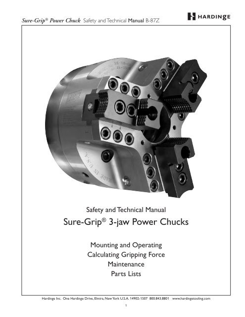
<strong>Sure</strong>-Grip ® <strong>Power</strong> <strong>Chuck</strong> Safety and Technical Manual B-87Z<br />
Safety and Technical Manual<br />
<strong>Sure</strong>-Grip ® 3-jaw <strong>Power</strong> <strong>Chuck</strong>s<br />
Mounting and Operating<br />
Calculating Gripping Force<br />
Maintenance<br />
Parts Lists<br />
Hardinge Inc. One Hardinge Drive, Elmira, New York U.S.A. 14902-1507 800.843.8801 www.hardingetooling.com<br />
1
<strong>Sure</strong>-Grip ® <strong>Power</strong> <strong>Chuck</strong> Safety and Technical Manual B-87Z<br />
Table of Contents:<br />
Chapter 1 – Safety Information, Instructions, Maintenance & Parts Lists<br />
General Safety Information & Warnings …………………………………………………………………………… 7-9<br />
Guidelines For Use ……………………………………………………………………………………………… 10-11<br />
<strong>Sure</strong>-Grip ® <strong>Chuck</strong> Specifications and Dimensions<br />
4" and 5" <strong>Chuck</strong>s ……………………………………………………………………………………………… 12<br />
6" <strong>Chuck</strong>s …………………………………………………………………………………………………… 13, 17<br />
8" <strong>Chuck</strong>s …………………………………………………………………………………………………… 14, 17<br />
10" <strong>Chuck</strong>s ………………………………………………………………………………………………… 15, 17<br />
12" <strong>Chuck</strong>s ………………………………………………………………………………………………… 16, 17<br />
Smallest Gripping Diameter for Pointed Soft Jaws—all <strong>Chuck</strong> Sizes ………………………………………………… 18<br />
Master Jaw Slot and T-Nut Specifications—all <strong>Chuck</strong> Sizes …………………………………………………… 18<br />
<strong>Sure</strong>-Grip Spindle Adapters—A2-5 to A2-6, A2-6 to A2-8, A2-11 to A2-8 ……………………………………… 19<br />
Machine Tools with Pneumatic Actuating Cylinders ………………………………………………………………… 19<br />
Maximum Static Gripping Force …………………………………………………………………………………… 20<br />
Maximum <strong>Chuck</strong> RPM ……………………………………………………………………………………………… 20<br />
Centrifugal Force …………………………………………………………………………………………………… 21<br />
Correlation Between Jaw Gripping Force, Spindle Speed and Jaw Position ………………………………………… 22<br />
Gripping Force Loss Due to <strong>Chuck</strong> Jaw Position …………………………………………………………… 22-24<br />
Jaw Height and Mass Gripping Force ……………………………………………………………………… 25-27<br />
Top Jaws Higher and/or Wider than Standard Height Top Jaws ………………………………………………… 25<br />
Hysteresis ……………………………………………………………………………………………………… 25<br />
Mounting Procedures<br />
Mounting a <strong>Chuck</strong> to the Machine Tool Spindle ………………………………………………………………… 28, 29<br />
Mounting & Removing <strong>Chuck</strong>s on Hardinge Horizontal Lathes ………………………………………………… 30-32<br />
Work Stop Plates ……………………………………………………………………………………………… 32<br />
Mounting Top Jaws to Master Jaws ……………………………………………………………………………… 33, 34<br />
Mounting the I-Beams and Top Jaws for Quick-Change <strong>Chuck</strong>s ……………………………………………… 34<br />
Mounting & Removing <strong>Chuck</strong>s on Non-Hardinge Machines—Two-piece Draw Bar …………………………… 35-39<br />
Preparing Link for <strong>Chuck</strong>s on Non-Hardinge Machines …………………………………………………… 35, 39<br />
Work Stop Plates ……………………………………………………………………………………………… 37<br />
Draw Bar Link Info Sheet ……………………………………………………………………………………… 39<br />
Mounting & Removing <strong>Chuck</strong>s on Hardinge-EMAG VL Vertical Lathes ………………………………………… 40, 41<br />
Mounting & Removing <strong>Chuck</strong>s on Hardinge VT100 & VT200 Vertical Lathes …………………………………… 42-45<br />
Machining Top Jaws ……………………………………………………………………………………………… 46-47<br />
Parts Lists/Periodic Safety and Maintenance Inspection<br />
4" <strong>Chuck</strong> Assembly for Hardinge Lathes—A2-4 Spindle …………………………………………………… 48, 49<br />
5" <strong>Chuck</strong> Assembly for Hardinge Lathes —A2-5 Spindle …………………………………………………… 50, 51<br />
5" <strong>Chuck</strong> Assembly for Other CNC Lathes—A2-5 Spindle ………………………………………………… 52, 53<br />
6" <strong>Chuck</strong> Assembly for Hardinge Lathes—A2-5 Spindle …………………………………………………… 54, 55<br />
6" <strong>Chuck</strong> Assembly for Hardinge Lathes—A2-6 Spindle …………………………………………………… 56, 57<br />
6" <strong>Chuck</strong> Assembly for Hardinge-EMAG VL3 Vertical Lathes—A2-5 Spindle ……………………………… 58, 59<br />
6" <strong>Chuck</strong> Assembly for Hardinge <strong>Chuck</strong>-Style Spindle and Other CNC Lathes—A2-5 Spindle …………… 60, 61<br />
8" <strong>Chuck</strong> Assembly for Hardinge Lathes—A2-5 Spindle …………………………………………………… 62, 63<br />
8" <strong>Chuck</strong> Assembly for Hardinge Lathes—A2-6 Spindle …………………………………………………… 64, 65<br />
8" <strong>Chuck</strong> Assembly for Hardinge-EMAG VL5 Vertical Lathes—A2-6 Spindle ……………………………… 66, 67<br />
8" <strong>Chuck</strong> Assembly for Hardinge <strong>Chuck</strong>-Style Spindle and Other CNC Lathes—(B-Version)—A2-6 Spindle 68, 69<br />
8" <strong>Chuck</strong> Assembly for Other CNC Lathes—Large Bore (C-Version)—A2-6 Spindle ……………………… 70, 71<br />
8" <strong>Chuck</strong> Assembly for Hardinge <strong>Chuck</strong>-Style Spindle Lathes—A2-6 Spindle ……………………………… 72, 73<br />
8" <strong>Chuck</strong> Assembly for Hardinge SR 200 Lathes—A2-6 Spindle …………………………………………… 74. 75<br />
10" <strong>Chuck</strong> Assembly for Hardinge Lathes—A2-6 Spindle …………………………………………………… 76, 77<br />
10" <strong>Chuck</strong> Assembly for Hardinge Lathes—A2-8 Spindle …………………………………………………… 78, 79<br />
10" <strong>Chuck</strong> Assembly for Hardinge VL5 Vertical Lathes—A2-6 Spindle ……………………………………… 80, 81<br />
10" <strong>Chuck</strong> Assembly for Hardinge VT100 & VT200 Vertical Lathes—A2-8 and A2-11 Spindle ……………… 82, 83<br />
Hardinge Inc. One Hardinge Drive, Elmira, New York U.S.A. 14902-1507 800.843.8801 www.hardingetooling.com<br />
2
<strong>Sure</strong>-Grip ® <strong>Power</strong> <strong>Chuck</strong> Safety and Technical Manual B-87Z<br />
10" <strong>Chuck</strong> Assembly for Hardinge and Other Lathes—(B-Version)—A2-8 Spindle ………………………… 84, 85<br />
10" <strong>Chuck</strong> Assembly for Other Lathes—Large Bore (C-Version)—A2-8 Spindle …………………………… 86. 87<br />
10" <strong>Chuck</strong> Assembly for Hardinge SR 250 Lathes—A2-8 Spindle ………………………………………… 88, 89<br />
12" <strong>Chuck</strong> Assembly for Hardinge Lathes—A2-8 Spindle …………………………………………………… 90, 91<br />
12" <strong>Chuck</strong> Assembly for Hardinge VT100 & VT200 Vertical Lathes—A2-8 and A2-11 Spindle ……………… 92, 93<br />
12" <strong>Chuck</strong> Assembly for Other Lathes—A2-8 Spindle ……………………………………………………… 94, 95<br />
Top Jaws …………………………………………………………………………………………………… 96, 97<br />
Chapter 2 – Calculating Gripping Force<br />
Gripping Force Introduction / Illustration …………………………………………………………………………… 100<br />
Parameter Definitions ……………………………………………………………………………………………… 100<br />
Gripping Force/RPM Diagrams—Gripping Force Loss Due to Jaw Location ………………………………… 101-103<br />
4" <strong>Chuck</strong> ……………………………………………………………………………………………………… 102<br />
5" and 6" <strong>Chuck</strong> ……………………………………………………………………………………………… 101<br />
8" <strong>Chuck</strong> ……………………………………………………………………………………………………… 102<br />
10" & 12" <strong>Chuck</strong> ……………………………………………………………………………………………… 103<br />
Jaw Height and Mass Gripping Force Chart …………………………………………………………………… 104-106<br />
4" <strong>Chuck</strong> ……………………………………………………………………………………………………… 105<br />
5" and 6" <strong>Chuck</strong> ……………………………………………………………………………………………… 104<br />
8" <strong>Chuck</strong> ……………………………………………………………………………………………………… 105<br />
10" & 12" <strong>Chuck</strong> ……………………………………………………………………………………………… 106<br />
Turning Operation<br />
Formula #1 Gripping Force …………………………………………………………………………………… 104-106<br />
Formula #2 Main Cutting Force …………………………………………………………………………………… 107<br />
Chip Cross Section (Table 1) ………………………………………………………………………………… 107<br />
<strong>Chuck</strong>ing Coefficient (Table 2) ………………………………………………………………………………… 108<br />
Specific Cutting Force Kc at Feed Sr (Table 3) ………………………………………………………………… 108<br />
<strong>Chuck</strong>ing Ratio (Table 4) ……………………………………………………………………………………… 109<br />
Determining the Length Factor (Table 5) ……………………………………………………………………… 110<br />
Formula #3 Initial Gripping Force—Centrifugal Forces …………………………………………………………… 110<br />
Draw Bar/Tube Force ………………………………………………………………………………………… 111<br />
Turning Example Calculation<br />
Centrifugal Forces of Jaws Corresponding to Rotational Speed ……………………………………………… 112-114<br />
4" <strong>Chuck</strong> ……………………………………………………………………………………………………… 113<br />
5" and 6" <strong>Chuck</strong> ……………………………………………………………………………………………… 112<br />
8" <strong>Chuck</strong> ……………………………………………………………………………………………………… 113<br />
10" & 12" <strong>Chuck</strong> ……………………………………………………………………………………………… 114<br />
Total Gripping Force / Draw Bar Force / Operating Pressure ………………………………………………… 115-117<br />
4" <strong>Chuck</strong> ……………………………………………………………………………………………………… 116<br />
5" and 6" <strong>Chuck</strong> ……………………………………………………………………………………………… 115<br />
8" <strong>Chuck</strong> ……………………………………………………………………………………………………… 116<br />
10" & 12" <strong>Chuck</strong> ……………………………………………………………………………………………… 117<br />
Other Cutting Tool Force Calculations ……………………………………………………………………………… 118<br />
Bolt Torque for all <strong>Chuck</strong>s and Jaws<br />
4", 5" and 6" <strong>Chuck</strong> …………………………………………………………………………………………… 119<br />
8" <strong>Chuck</strong> ……………………………………………………………………………………………………… 120<br />
10" <strong>Chuck</strong> ……………………………………………………………………………………………………… 121<br />
12" <strong>Chuck</strong> ……………………………………………………………………………………………………… 122<br />
Warranty<br />
The seller warrants to the original Buyer only those products manufactured by the Seller or through an authorized<br />
representative and used by the original Buyer within limits of rated and normal usage will be free from defects which are<br />
not commercially acceptable in material and workmanship for the following periods, measured from the date of shipment:<br />
6 months for repair parts purchased after the original warranty expires; 12 months for all models of Hardinge ® <strong>Sure</strong>-Grip ®<br />
3 Jaw <strong>Power</strong> <strong>Chuck</strong>s. Hardinge will not sell Hardinge <strong>Sure</strong>-Grip chuck bodies as a replacement part. If this part requires<br />
replacement the complete chuck must be returned to Hardinge for rebuilding.<br />
Hardinge Inc. One Hardinge Drive, Elmira, New York U.S.A. 14902-1507 800.843.8801 www.hardingetooling.com<br />
3
<strong>Sure</strong>-Grip ® <strong>Power</strong> <strong>Chuck</strong> Safety and Technical Manual B-87Z<br />
Hardinge Inc. One Hardinge Drive, Elmira, New York U.S.A. 14902-1507 800.843.8801 www.hardingetooling.com<br />
4
<strong>Sure</strong>-Grip ® <strong>Power</strong> <strong>Chuck</strong> Safety and Technical Manual B-87Z<br />
Chapter 1<br />
Safety Information<br />
Instructions<br />
Maintenance<br />
Parts Lists<br />
Hardinge Inc. One Hardinge Drive, Elmira, New York U.S.A. 14902-1507 800.843.8801 www.hardingetooling.com<br />
5
<strong>Sure</strong>-Grip ® <strong>Power</strong> <strong>Chuck</strong> Safety and Technical Manual B-87Z<br />
NOTES:<br />
Hardinge Inc. One Hardinge Drive, Elmira, New York U.S.A. 14902-1507 800.843.8801 www.hardingetooling.com<br />
6
<strong>Sure</strong>-Grip ® <strong>Power</strong> <strong>Chuck</strong> Safety and Technical Manual B-87Z<br />
General Safety Information<br />
Before placing the Hardinge ® <strong>Sure</strong>-Grip ® <strong>Power</strong> <strong>Chuck</strong> on your machine tool, thoroughly read this manual and understand<br />
the information. If you are uncertain about any of the information, see your immediate supervisor. Also make certain that<br />
you understand the information in your machine tool operator’s, programmer’s and maintenance manuals.<br />
NOTICE<br />
Damage resulting from misuse, negligence or accidents<br />
is not covered by the Hardinge <strong>Sure</strong>-Grip <strong>Power</strong> <strong>Chuck</strong> Warranty.<br />
Information in this document is subject to change without notice.<br />
In no event will Hardinge Inc. be responsible for indirect or consequential damage<br />
resulting from the use or application of the product, or any of the information in this document.<br />
This product is only to be used by trained machinists skilled<br />
in the use and operation of power chucks on metal cutting machines.<br />
Machine Tool Setup/Operators Responsibilities:<br />
• Hazards may arise from the characteristics of the workpiece and machine used with a given workholding chuck<br />
even if the specific requirements in this manual are met. The user shall therefore consider such characteristics of<br />
workpieces (dimensions, mass and shape), and of machines (operating speed, feed and depth of cut) in order to<br />
remove or reduce the hazard.<br />
• The maximum permissible speed for the specific machining shall be determined by the user on the basis of the<br />
clamping forces required. This speed shall not exceed the maximum rotational speed of the workholding chuck.<br />
• For special top jaws, the user should calculate the dynamic clamping force for a particular workholding chuck<br />
according to the one method outlined in this manual. Other methods are available from publications referred to<br />
on page 118.<br />
• Static clamping force measuring devices should be used to check maintenance conditions at regular intervals<br />
according to the information in this manual.<br />
• Residual risks may arise from a failure to achieve a satisfactory quality of rotational balance.<br />
• To prevent excessive force being applied to a particular workholding chuck, the actuating force available from a<br />
machine may need to be reduced.<br />
– WARNINGS –<br />
Warnings must be followed carefully to avoid the possibility of personal injury and or damage to the chuck,<br />
machine tool, tooling, or the workpiece. In this publication the term "personal injury" should be understood<br />
to include severe personal injury, possibly resulting in death.<br />
– CAUTIONS –<br />
Cautions must be followed carefully to avoid the possibility of damage to the chuck,<br />
machine tool, tooling, or workpiece.<br />
– NOTES –<br />
Notes contain supplemental information.<br />
Hardinge Inc. One Hardinge Drive, Elmira, New York U.S.A. 14902-1507 800.843.8801 www.hardingetooling.com<br />
7
<strong>Sure</strong>-Grip ® <strong>Power</strong> <strong>Chuck</strong> Safety and Technical Manual B-87Z<br />
For Safe Operation of Hardinge ® <strong>Sure</strong>-Grip ® Thru-Hole <strong>Power</strong> <strong>Chuck</strong>s<br />
Please carefully read this manual, paying close attention to the safety instructions, warnings and cautions before installation<br />
and operation of your chuck. Hardinge will not assume responsibility for damage or accidents caused by the misuse of a<br />
Hardinge <strong>Sure</strong>-Grip <strong>Chuck</strong> through noncompliance with the safety, operating, and maintenance instructions in this manual<br />
and the safety, operations and maintenance instructions in the machine tool’s manuals.<br />
– WARNING –<br />
HAZARDS ................................................................. It is the user's responsibility to make certain that all machine tool safety, operation, and maintenance<br />
instructions and accessory safety, operation, and maintenance instructions are taken into consideration<br />
before operating the power chuck. (Ignoring this warning may cause damage to the machine<br />
and/or personal injury.)<br />
MAXIMUM PERMISSIBLE RPM ......... (Spindle speed) shall be determined by the user on the basis of the gripping force required for the<br />
specific machining application. It shall not exceed the maximum recommended spindle speed (RPM) of<br />
the power chuck (pages 12-17). The maximum chuck RPM may only be used at the maximum applied<br />
draw bar force and with a properly operating chuck. (Ignoring this warning may cause damage to<br />
the machine and/or personal injury.)<br />
DYNAMIC GRIPPING FORCE .............. for special top jaws, as well as standard height, medium height and hard top jaws, shall be calculated by<br />
the user in conjunction with the related chuck according to the method given in this manual. (Ignoring<br />
this warning may cause damage to the machine and/or personal injury.)<br />
STATIC GRIPPING FORCE...................... measuring devices shall be used to check the gripping force of the power chuck at regular intervals<br />
according to the operation and maintenance information in this manual. (Ignoring this warning may<br />
cause damage to the machine and/or personal injury.)<br />
TURN OFF POWER ...................................... before changing, inspecting, lubricating or setting the chuck. (If machine is accidently started, there<br />
may be damage to the machine and/or personal injury.)<br />
NEVER OPERATE ............................................ the Open or Close switches on the control while the spindle is rotating. (Jaws may open, allowing<br />
the workpiece to come out, causing damage to the machine and/or personal injury.)<br />
DO NOT EXCEED ............................................ maximum recommended spindle RPM even when using the maximum recommended draw bar force.<br />
(<strong>Chuck</strong> may be damaged and/or the workpiece may come out, damaging the machine tool<br />
and/or injuring the operator.)<br />
NEVER START ..................................................... the machine with the machine doors open. (The workpiece or the jaws may come out, causing<br />
damage to the machine and/or personal injury.)<br />
"T" NUTS ................................................................... should never extend beyond the OD of the chuck body. (The jaws will not be held securely to<br />
the chuck which may cause the jaws to come off, or the workpiece to come out of the jaws,<br />
causing damage to the machine and/or personal injury.)<br />
NEVER EXCEED ................................................. the maximum draw bar/tube force of the chuck (Pages 12-17). (<strong>Chuck</strong> and mounting bolts may be<br />
damaged, causing the chuck, jaws or workpiece to come off, causing damage to the<br />
machine and/or personal injury.)<br />
ALWAYS CHECK THE STROKE ......... of the machine tool’s draw bar. It should be greater than or equal to the draw bar stroke of the chuck.<br />
If the machine’s stroke is less than the chuck's, the jaw stroke will be reduced proportionately. (The<br />
jaw stroke may not be adequate to handle the tolerance variation of the workpiece chucking<br />
diameter, causing damage to the machine and/or personal injury.)<br />
HEAVY DUTY GUARD ................................ must be installed around the chuck when being used on an unshielded machine tool. (If a jaw breaks<br />
and/or a workpiece comes loose without a guard installed, there may be damage to the<br />
machine and/or personal injury.)<br />
POWER FAILURE .............................................. can shut your machine down. Always check your chuck to make certain that you have full chucking<br />
force before continuing production. Even though your machine tool rotating draw tube has check<br />
valves to maintain chucking pressure in this type circumstance, always check your chuck.<br />
(Noncompliance may cause damage to the machine, the chuck, and/or personal injury.)<br />
PROPERLY TORQUE ...................................... the bolts for mounting the chuck to the spindle and mounting the jaws to the chuck. Over-torque of<br />
the bolts may cause cracks and under-torque may allow the bolts to loosen (Pages 119-122).<br />
(Not complying with the torque specifications may cause damage to the machine and/or<br />
personal injury.)<br />
BACK OF TOP JAWS MUST NOT .... extend beyond the outside diameter of the chuck. This condition creates extremely high centrifugal<br />
forces which may allow the workpiece to come out of the jaw and/or fatigue and fracture the jaws.<br />
(These conditions may cause damage to the machine and/or personal injury.)<br />
Hardinge Inc. One Hardinge Drive, Elmira, New York U.S.A. 14902-1507 800.843.8801 www.hardingetooling.com<br />
8
<strong>Sure</strong>-Grip ® <strong>Power</strong> <strong>Chuck</strong> Safety and Technical Manual B-87Z<br />
– WARNING –<br />
JAW HEIGHT ......................................................... should be within the maximum gripping force limits. (When jaws are too high and the maximum<br />
gripping force limits are exceeded, the workpiece may come out of the chuck, causing<br />
damage to the machine and/or personal injury.)<br />
INTERNAL CHUCKING ............................. requires a reduction of the gripping force because centrifugal force adds additional gripping force<br />
which could distort the part or cause the part to fracture after material has been removed. The necessary<br />
pressure reduction may be as low as 20% and when working with thin wall parts higher than<br />
50%. The user must determine the gripping force required for each specific workpiece. (The workpiece<br />
may come off of the jaws, causing damage to the machine and/or personal injury.)<br />
LONG WORKPIECES .................................... require the use of a tailstock center or a steady rest. Workpieces are considered long when the length<br />
is approximately three (3) times its diameter. For example a 1" diameter part 3 1 /2" long would require<br />
a tailstock, a piece 2 3 /4" long would not. This applies only if the part is gripped by the complete height<br />
of the jaw. If the part is gripped in a stepped jaw, the ratio decreases accordingly. For example a 1"<br />
diameter part 2 1 /2" long gripped 1 /4" deep in stepped jaws would require a tailstock. (The workpiece<br />
may come out of the jaws, causing damage to the machine and/or personal injury.)<br />
HEAVY CUTS ........................................................ at high RPM’s can cause part slippage and/or cause the workpiece to come loose. (The workpiece<br />
may come out of the jaws, causing damage to the machine and/or personal injury.)<br />
DO NOT MODIFY ............................................. the chuck body, top plate, T-nuts or other components. Any modification will cause the chuck to be<br />
out of balance. See additional note under THE CHUCK BALANCE on this page. (Any modification<br />
may cause the chuck to fail, causing damage to the machine and/or personal injury.)<br />
NEVER OPERATE .............................................. the machine tool and chuck while under the influence of alcohol, drugs, controlled substances or<br />
prescription medication. (Ignoring this warning may cause damage to the machine and/or personal<br />
injury.)<br />
DO NOT WEAR ................................................... gloves, ties, jewelry, watches, loose clothing or long hair when operating a machine tool and/or chuck.<br />
(Ignoring this warning may cause damage to the machine and/or personal injury.)<br />
WHEN LIFTING ................................................. the chuck, use the eyebolt and a hoist. For chucks that do not have an eyebolt, use a lifting strap of<br />
sufficient strength capabilities and a hoist. (Personal injury, damage to the machine and/or the<br />
chuck may result from improper lifting of the chuck.)<br />
KEEP HANDS OUT ......................................... of the gripping area of the chuck when gripping a workpiece. (Ignoring this warning may cause<br />
damage to the machine and/or personal injury.)<br />
NEVER HAMMER ............................................... the chuck, jaws or workpiece. (<strong>Chuck</strong> may be damaged resulting in the workpiece and/or jaws<br />
coming off, causing damage to the machine and/or personal injury.)<br />
THE CHUCK BALANCE ............................ is critical. The chuck is precision-balanced (ISO - G6.3) during the manufacturing process at Hardinge ® .<br />
If a chuck has been damaged and repaired, it should not be used until it has been precision balanced<br />
by a qualified technician. (Unbalanced chucks may allow parts to come loose, causing damage<br />
to the machine and/or personal injury.)<br />
GREASE CHUCK ............................................... a minimum of once every 24 hours. More frequent lubrication may be required when using non-water<br />
based coolants or when workpiece production results in very short cycle times. (Insufficient lubrication<br />
may result in lower gripping forces at the workpiece, allowing the workpiece to come<br />
loose, causing damage to the machine and/or personal injury.)<br />
ONLY SPINDLE ADAPTERS ...............................manufactured or recommended by Hardinge can be used with <strong>Sure</strong>-Grip ® power chucks. (Improper<br />
materials and machine spindle specifications may cause improper mating of the spindle<br />
and/or the chuck as well as failure of the material. The chuck and/or spindle adapter may<br />
come loose or break apart, causing damage to the machine and/or personal injury.)<br />
ONLY TOP JAWS ................................................ manufactured or recommended by Hardinge should be used on <strong>Sure</strong>-Grip chucks. (Improper<br />
mat-erials and machining specifications may cause jaws to fail, causing damage to the<br />
machine and/or personal injury.)<br />
LENGTH OF TOP JAW BOLTS .................... is critical. If bolts are too long they will bottom out in the master jaw before the jaw is securely locked.<br />
(The unstable jaw may release the workpiece, causing damage to the machine and/or<br />
personal injury - see page 33.)<br />
COLLISIONS .......................................................... After any collision, the jaws and the chuck must be removed and checked for any cracks, out-of-<br />
balance, or damage. The chuck must be disassembled and all parts checked for cracks and damage.<br />
The chuck must not be used unless certified by a person with proper credentials. (Ignoring this<br />
warning may cause damage to the machine and/or personal injury.)<br />
DAMAGED BOLTS ........................................... Worn or damaged bolts used to hold the jaws to the chuck and/or used to mount the chuck to the<br />
spindle must be replaced with new bolts. The bolts must meet DIN912 12.9, ISO 4762, or ANS B<br />
18.3.1M specifications. (Ignoring this warning may cause damage to the machine and/or<br />
personal injury.)<br />
Hardinge Inc. One Hardinge Drive, Elmira, New York U.S.A. 14902-1507 800.843.8801 www.hardingetooling.com<br />
9
<strong>Sure</strong>-Grip ® <strong>Power</strong> <strong>Chuck</strong> Safety and Technical Manual B-87Z<br />
GUIDELINES FOR USING POWER OPERATED CHUCKS<br />
When mounting the Hardinge ® <strong>Sure</strong>-Grip ® <strong>Chuck</strong> on a lathe for heavy-duty machining at high spindle speeds, certain<br />
criteria must be taken into consideration to ensure safe operation of the chuck as well as the machine tool.<br />
Machine tools other than Hardinge may require an actuating cylinder and draw bar to operate the chuck. The following<br />
safety requirements must be met for these configurations as well as those mounted on Hardinge lathes. Make sure the<br />
machine tool has the following features before mounting the Hardinge <strong>Sure</strong>-Grip <strong>Chuck</strong>, and that each of these features<br />
function properly.<br />
• Spindle Start: The spindle cannot be allowed to rotate until the clamping pressure has built up in the actuating<br />
cylinder and the clamping has taken place.<br />
• Open <strong>Chuck</strong>: The chuck may not be opened until the spindle has come to a complete stop.<br />
• Hydraulic or Pneumatic <strong>Power</strong> Failure: The workpiece must stay firmly gripped in the chuck jaws until the<br />
spindle has come to a complete stop.<br />
• Electrical <strong>Power</strong> Failure: After an electrical power failure, the workpiece must stay firmly gripped in the chuck<br />
jaws until the spindle has come to a complete stop. When the electricity is resumed, the chuck must still firmly<br />
grip the part so as not to release it. The user must make certain after any electrical power failure that all functions<br />
of the machine work properly before operating the chuck or the machine tool.<br />
• Draw Bar Pressure Failure: If the pressure fails going to the actuating cylinder, a signal must stop the machine<br />
spindle.<br />
• Safety Instructions: The safety instructions given in the machine tool operations manual and maintenance<br />
manual must be strictly followed. When using a second-source actuating cylinder, the safety instructions given in its<br />
operation's manual must also be strictly followed.<br />
<strong>Chuck</strong> Functioning (See ISO TR 13618 Recommendations for the User)<br />
After mounting the chuck, the following must be checked by the operator/setup person before operating the chuck on<br />
the machine tool:<br />
• Clamping Force: The clamping force found in the chuck operation manual must be obtainable at the<br />
maximum recommended draw bar force.<br />
• Stroke Safety Range: A safety stroke limit must be provided for both the forward and back positions.<br />
The machine spindle can only start after the draw bar has moved enough to safely close the chuck.<br />
• RPM Limit: The machine tool must be equipped with a speed limitation device to make certain that the spindle<br />
RPM of the machine does not exceed the maximum RPM limitations of the chuck.<br />
• Adjustable Stroke Limits: When a different size or manufacturer of chuck is mounted to the machine spindle,<br />
the draw bar stroke limit must be adjustable to meet these new specifications.<br />
• Centrifugal Force: The centrifugal force of the clamping jaws must be taken into consideration when<br />
calculating the required clamping for machining a workpiece.<br />
<strong>Chuck</strong> Maintenance<br />
The chuck will only operate properly when the maintenance instructions are precisely followed as outlined in the operation's<br />
manual for the chuck. The following practices must be followed:<br />
• Only lubricants specified in the operation's manual must be used. An unsuitable lubricant can unexpectedly<br />
reduce the clamping force dramatically. Use Chevron Ultra-Duty EP NLGI 2, Dow Corning BR-Plus, or Kluber<br />
ALTEMP Q NB 50 grease.<br />
• A pressure gun must be used to make certain that the lubricant reaches all the surfaces requiring<br />
lubrication.<br />
• The chuck must be actuated several times through its complete stroke in order for the lubricant to reach<br />
all surfaces. After this has been done, repeat the lubrication and then check the clamping force of the chuck.<br />
Hardinge Inc. One Hardinge Drive, Elmira, New York U.S.A. 14902-1507 800.843.8801 www.hardingetooling.com<br />
10
<strong>Sure</strong>-Grip ® <strong>Power</strong> <strong>Chuck</strong> Safety and Technical Manual B-87Z<br />
Clamping Force Check<br />
• Before starting a machining operation or when changing jobs, and in between the maintenance intervals,<br />
the clamping force should be checked by means of a clamping force gage. Regular checks will ensure the optimum<br />
performance of the chuck.<br />
Full Stroke Schedule<br />
• The chuck jaws should be moved through their complete stroke range once every twenty-four hours. This<br />
practice will return any lubricant that has been pushed away from the pressure surfaces. The clamping force will<br />
be maintained for a longer period of time as well as reducing wear to these surfaces.<br />
Special Jaws<br />
When using jaws configured different than the standard jaws, the following instructions must be followed:<br />
• Jaw Height and Weight: The special jaws must be designed in such a way that their weight and height is as low<br />
as possible. The clamping point should be as close to the face of the chuck as possible. A clamping point which<br />
is at a higher distance may cause greater surface pressure on the sliding surfaces, thus considerably reducing the<br />
clamping force as well as decreasing the life of the chuck. Many times special jaws are required by the part configuration<br />
but do not require the mass of the large top jaw. In these instances, remove as much mass as possible and<br />
still safely grip the workpiece.<br />
• Calculating the rated speed: If the special jaws are wider and/or higher than the hardened and ground single<br />
step jaws, the resulting higher centrifugal forces must be taken into consideration when calculating the required<br />
clamping pressure and RPM. For calculating the rated speed for a certain machining operation, the following<br />
formula must be applied:<br />
Fspo = initial clamping force at 0 RPM (measure in Newtons [N])<br />
Fspz = required clamping force with chuck at 0 RPM for a certain machining task<br />
(measure in Newtons [N])<br />
nmax = maximum admissible speed (RPM)<br />
m = mass of the entire jaw unit (kg)chuck and top jaws<br />
rc = center of gravity radius of the entire jaw unit (m)<br />
a = number of jaws<br />
• Welded Jaws: Welded jaws should not be used. If absolutely necessary, the weld seams must be checked as to<br />
their centrifugal and clamping force capacity.<br />
• Mounting Screws: Mounting screws must be positioned for maximum holding.<br />
Hardinge Inc. One Hardinge Drive, Elmira, New York U.S.A. 14902-1507 800.843.8801 www.hardingetooling.com<br />
11
<strong>Sure</strong>-Grip ® <strong>Power</strong> <strong>Chuck</strong> Safety and Technical Manual B-87Z<br />
Parts List: 4" <strong>Chuck</strong> Assembly for Hardinge ® Lathes—A2-4 Spindle<br />
Assembly for Hardinge ELITE ® 27 MS and QUEST ® GT:<br />
Model No. Part Number Description<br />
HM304 SCA 2000304A24H Standard <strong>Chuck</strong> – 1.5mm x 60° Master Jaw Serrations<br />
Parts List:<br />
Item Qty Part Number Description<br />
1 6 MS 0573614 Socket Set Screw -Flat [M6 x 1 x 8mm] (DIN912 12.9, ISO 4762, or ANS B 18.3.1M specs)<br />
2 3 SC 0000223 "T" Nut for Metric Serrations -Soft Jaws (.551" bolt spacing) Must use Hardinge T-Nuts<br />
3 3 SC 2000222 Soft Top Jaw<br />
4 6 MS 0103818 Socket Head Cap Screw [M8 x 1.25 x 20] (DIN912 12.9, ISO 4762, or ANS B 18.3.1M specs)<br />
6 3 SC 0000060 Pin<br />
7 6 CE 0001851 Fitting, Alemite No. 1851<br />
8 3 0100310 Socket Head Cap Screw [#10-32 x 5/8"] (DIN912 12.9, ISO 4762, or ANS B 18.3.1M specs)<br />
9 3 SC 0000202 Counter Weight<br />
10 3 SC 0000208 Lever<br />
11 3 SC 0000221 Master Jaw Metric Serrations (1.5mm x 60° serrations)<br />
Kit 1 SC 2000221 S 3 Master Jaws (item 11), Shields (item 14), Escutcheon Pins (item 15)<br />
12 1 SC 0000206 Top Plate<br />
13 15 MS 0103617 Socket Head Cap Screw [M6 x 1 x 16] (DIN912 12.9, ISO 4762, or ANS B 18.3.1M specs)<br />
14 3 SC 0000055 Chip Shield<br />
15 6 R 0008044 Escutcheon Pin<br />
16 1 SC 0000213 <strong>Chuck</strong> Draw Bar (QUEST ® GT and ELITE ® 27 MS)<br />
17 1 SCA 0000003 Key<br />
18 1 replacement N/A <strong>Chuck</strong> Body (Send entire chuck assembly to Hardinge if chuck body is damaged)<br />
19 3 0101249 Socket Head Cap Screw [7/16"-14 x 3-1/4"] (DIN912 12.9, ISO 4762, or ANS B 18.3.1M specs)<br />
20 3 MS 0104030 Socket Head Cap Screw [M10 x 1.5 x 80] (DIN912 12.9, ISO 4762, or ANS B 18.3.1M specs)<br />
21 0 CE 0000002 Grease—Chevron Ultra-Duty EP NLGI 2 (Dow Corning BR-2 Plus or Kluber ALTEMP Q NB 50 avail)<br />
22 1 CE 0000737 Nozzle, Alemite No. Z-737 (Adapter for Grease Gun)<br />
23 0 NC 0010884 Loctite #242<br />
24 1 B 0009500-0087 Safety and Technical Manual<br />
29 3 MS-0554017-SS Balancing Set Screw (M10x1.5x16mm) Length of screws may vary<br />
WARNING: You must use Hardinge T-nuts. (Ignoring this warning may result in machine and/or personal injury)<br />
Top Jaws for Hardinge <strong>Sure</strong>-Grip ® <strong>Chuck</strong>s — 1.5mm x 60° Metric Serrations<br />
Model No. Part Number Description<br />
4MSHF SC 2000225 Standard Height Soft Flat Top Jaw<br />
4MMHF SC 2000226 Medium Height Soft Flat Top Jaw<br />
4MSHP SC 2000222 Standard Height Soft Pointed Top Jaw<br />
4MMHP SC 2000227 Medium Height Soft Pointed Top Jaw<br />
4MH1 SC 2000224 Hard Single Step Top Jaw<br />
NOTE: Only jaws manufactured by Hardinge Inc. or jaws approved by Hardinge are to be used on <strong>Sure</strong>-Grip <strong>Power</strong> <strong>Chuck</strong>s.<br />
Hardinge Inc. One Hardinge Drive, Elmira, New York U.S.A. 14902-1507 800.843.8801 www.hardingetooling.com<br />
48
<strong>Sure</strong>-Grip ® <strong>Power</strong> <strong>Chuck</strong> Safety and Technical Manual B-87Z<br />
Bolt Torque Specs<br />
on pages 119-122<br />
4" <strong>Sure</strong>-Grip ® <strong>Power</strong><br />
<strong>Chuck</strong> for<br />
Hardinge ® Lathes<br />
– A2-4 Spindle –<br />
Periodic Safety Inspection—Every 6 Months or After an Accident or Collision<br />
(This inspection should be done after the chuck has been removed from the lathe spindle)<br />
NOTE: The parts for each jaw location (pin, lever, master jaw, t-nuts and top jaw) should be kept together for reassembly. If assembled into a different<br />
location the chuck will not be balanced and the strokes may not be within specifications.<br />
• Loosen the bolts (4) and raise and slide the jaws with the T-nuts (2) (5) from the slot in the master jaw.<br />
• Remove the twelve socket-head cap screws (13) from the top plate.<br />
• Remove the top plate (12).<br />
• Remove the three master jaws (11). It is not necessary to disassemble items (7) (14) (15).<br />
• Remove three set screws (29) and record the depth and location. Balance screws may be different lengths / depths and must be replaced in the same<br />
holes and to the same depth.<br />
• Remove six set screws (1) which lock in pivot pin (6). Do not remove item (7).<br />
• Remove Pivot Pin (6).<br />
• Remove Lever/counterweight assembly (8) (9) (10). Do not disassemble.<br />
• Remove <strong>Chuck</strong> Draw Bar (16). Do not disassemble item (17).<br />
Check all parts, including mounting bolts (4)(13)(19) for hairline cracks, fissures, and excessive wear. Replace all damaged parts.<br />
NOTE: If the chuck body is damaged, the entire chuck assembly must be sent back to Hardinge Inc. for rebuilding.<br />
• Clean all parts.<br />
• Lubricate all moving parts with Chevron Ultra-Duty EP NLGI 2, Dow Corning BR-2-Plus, or Kluber ALTEMP Q NB 50 grease.<br />
• Reassemble parts in the reverse order they were disassembled. Use Loctite as indicated on drawing by #23.<br />
• Use pressure gun with adapter (22) to grease pivot pin (7) with Chevron Ultra-Duty EP NLGI 2, Dow Corning BR-2-Plus, or Kluber ALTEMP Q NB 50<br />
grease.<br />
• Use pressure gun with adapter (22) to lightly grease master jaws (11) with Chevron Ultra-Duty EP NLGI 2, Dow Corning BR-2-Plus, or Kluber ALTEMP<br />
Q NB 50 grease. Move jaws through their full stroke several times.<br />
• After mounting chuck to machine tool, again grease the master jaws, then move the jaws through their full stroke under power. Grease the jaws again<br />
and cycle under power. This process makes certain all surfaces are lubricated properly.<br />
Hardinge Inc. One Hardinge Drive, Elmira, New York U.S.A. 14902-1507 800.843.8801 www.hardingetooling.com<br />
49
<strong>Sure</strong>-Grip ® <strong>Power</strong> <strong>Chuck</strong> Safety and Technical Manual B-87Z<br />
Parts List: 5" <strong>Chuck</strong> Assembly for Hardinge ® Lathes—A2-5 Spindle<br />
Assembly for Hardinge CHNC ® , CONQUEST ® T42, COBRA ® 42, QUEST ® & ELITE ® 6/42 and RS 42:<br />
Model No. Part Number Description<br />
HM305 SCA 2000305A25H Standard <strong>Chuck</strong> – 1.5mm x 60° Master Jaws<br />
Parts List:<br />
Item Qty Part Number Description<br />
1 6 MS 0573614 Socket Set Screw [M6 x 1x 8mm] (DIN912 12.9, ISO 4762, or ANS B 18.3.1M specs)<br />
2 3 SC 0000067 "T" Nut Round - for Metric Serrations - Hard & Soft Jaws - (Item 22 also required) - Must use Hardinge "T" Nuts<br />
3 3 SC 2000066 Soft Top Jaw<br />
4 6 MS 0103819 Socket Head Cap Screw [M8x1.25x25mm] (DIN912 12.9, ISO 4762, or ANS B 18.3.1M specs)<br />
5 3 SC 0000060 Pin<br />
6 6 CE 0001851 Fitting, Alemite No. 1851<br />
7 1 replacement N/A <strong>Chuck</strong> Body (Send entire chuck assembly to Hardinge if chuck body is damaged)<br />
8 3 SC 0000058 Lever<br />
9 3 SCA 0000064 Master Jaw with Metric Serrations<br />
Kit 1 SCA 2000064 S Three Master Jaws (9), Shields (12) Escutcheon Pins (13)<br />
10 1 SC 0000056 Top Plate<br />
11 12 MS 0103817 Socket Head Cap Screw [M8x1.2x16mm] (DIN912 12.9, ISO 4762, or ANS B 18.3.1M specs)<br />
12 3 SC 0000055 Chip Shield<br />
13 6 R 0008044 Escutcheon Pin<br />
14 3 MS 0104030 Socket Head Cap Screw [M10x1.5x80mm] (DIN912 12.9, ISO 4762, or ANS B 18.3.1M specs)<br />
15 1 SC 0000063 <strong>Chuck</strong> Draw Bar (CHNC, CONQUEST T42, COBRA 42, QUEST & ELITE 6/42, RS 42)<br />
16 1 SCA 0000003 Key<br />
17 3 0101248 Socket Head Cap Screw [7/16"-14 x 3"] (DIN912 12.9, ISO 4762, or ANS B 18.3.1M specs)<br />
18 3 SC 0000052 Counter Weight<br />
19 3 0100308 Socket Head Cap Screw [#10-32 x 1/2"] (DIN912 12.9, ISO 4762, or ANS B 18.3.1M specs)<br />
20 1 CE 0000737 Nozzle, Alemite No. Z-737<br />
21 0 CE 0000002 Grease—Chevron Ultra-Duty EP NLGI 2 (Dow Corning BR-2 Plus, or Kluber ALTEMP Q NB 50 avail.)<br />
22 3 SC 0000065 "T" Nut for Metric Serrations - (Item 2 also required) Must use Hardinge "T" Nuts<br />
23 0 NC 0010884 Loctite #242<br />
24 1 B 0009500-0087 Safety and Technical Manual<br />
29 3 MS-0554017-SS Balancing Set Screw [M10x1.5x16mm] Length of screws may vary<br />
WARNING: You must use Hardinge T-nuts. (Ignoring this warning may result in machine and/or personal injury)<br />
Top Jaws for Hardinge <strong>Sure</strong>-Grip <strong>Chuck</strong>s — 1.5mm x 60° Metric Serrations<br />
Model No. Part Number Description<br />
5MSHF SC 2000070 Standard Height Soft Flat Top Jaw<br />
5MMHF SC 2000071 Medium Height Soft Flat Top Jaw<br />
5MSHP SC 2000066 Standard Height Soft Pointed Top Jaw<br />
5MMHP SC 2000073 Medium Height Soft Pointed Top Jaw<br />
5MH1 SC 2000072 Hard Single Step Top Jaw<br />
NOTE: Only jaws manufactured by Hardinge Inc. or jaws approved by Hardinge are to be used on <strong>Sure</strong>-Grip <strong>Power</strong> <strong>Chuck</strong>s.<br />
Hardinge Inc. One Hardinge Drive, Elmira, New York U.S.A. 14902-1507 800.843.8801 www.hardingetooling.com<br />
50
<strong>Sure</strong>-Grip ® <strong>Power</strong> <strong>Chuck</strong> Safety and Technical Manual B-87Z<br />
Bolt Torque Specs<br />
on pages 119-122<br />
5" <strong>Sure</strong>-Grip ® <strong>Power</strong><br />
<strong>Chuck</strong> for<br />
Hardinge ® Lathes<br />
– A2-5 Spindle –<br />
Periodic Safety Inspection—Every 6 Months or After an Accident or Collision<br />
(This inspection should be done after the chuck has been removed from the lathe spindle)<br />
NOTE: The parts for each jaw location (pin, lever, master jaw, t-nuts and top jaw) should be kept together for reassembly. If assembled into a different<br />
location the chuck will not be balanced and the strokes may not be within specifications.<br />
• Loosen the bolts (4) and raise and slide the jaws with the T-nuts (2) from the slot in the master jaw.<br />
• Remove the twelve socket-head cap screws (11) from the top plate.<br />
• Remove the top plate (10).<br />
• Remove the three master jaws (9). It is not necessary to disassemble Items (6) (12) (13).<br />
• Remove three set screws (29) and record depth and location. Balance screws may be different lengths / depths and must be replaced in the same holes<br />
and to the same depth.<br />
• Remove six set screws (1) which lock in pivot pin (5). Do not remove item (6).<br />
• Remove Pivot Pin (5).<br />
• Remove Lever/counterweight assembly (8) (18) (19). Do not disassemble.<br />
• Remove <strong>Chuck</strong> Draw Bar (15). Do not disassemble item (16).<br />
Check all parts including mounting bolts (4)(14)(17) for hairline cracks, fissures, and excessive wear. Replace all damaged parts.<br />
WARNING: If the chuck body is damaged, the entire chuck assembly must be sent back to Hardinge ® for rebuilding.<br />
• Clean all parts.<br />
• Lubricate all moving parts with Chevron Ultra-Duty EP NLGI 2, Dow Corning BR-2-Plus, or Kluber ALTEMP Q NB 50 grease.<br />
• Reassemble parts in the reverse order they were disassembled. Use Loctite #242 (23) on bolts (1)(11)(29).<br />
• Use a pressure gun to grease pivot pin (5) with Chevron Ultra-Duty EP NLGI 2, Dow Corning BR-2-Plus, or Kluber ALTEMP Q NB 50 grease.<br />
• Use a pressure gun to lightly grease master jaws (9) with Chevron Ultra-Duty EP NLGI 2, Dow Corning BR-2-Plus, or Kluber ALTEMP Q NB 50 grease.<br />
Move jaws through their full stroke several times.<br />
• After mounting chuck to machine tool, again grease the master jaws, then move the jaws through their full stroke under power. Grease the jaws again<br />
and cycle under power. This process makes certain all surfaces are lubricated properly.<br />
Hardinge Inc. One Hardinge Drive, Elmira, New York U.S.A. 14902-1507 800.843.8801 www.hardingetooling.com<br />
51
<strong>Sure</strong>-Grip ® <strong>Power</strong> <strong>Chuck</strong> Safety and Technical Manual B-87Z<br />
Parts List: 5" <strong>Chuck</strong> Assembly for Other CNC Lathes—A2-5 Spindle<br />
Assembly for Other CNC Lathes:<br />
Model No. Part Number Description<br />
CM2-305B-5 SCA 2200305 A25C Standard <strong>Chuck</strong> – 1.5mm x 60° Master Jaws<br />
Parts List:<br />
Item Qty Part Number Description<br />
1 6 MS 0573614 Socket Set Screw [M6 x 1x 8mm] (DIN912 12.9, ISO 4762, or ANS B 18.3.1M specs)<br />
2 3 SC 0000067 "T" Nut - Round - for Metric Serrations - Hard & Soft Jaws - (Item 22 also required) - Must use Hardinge "T" Nuts<br />
3 3 SC 2000066 Soft Top Jaw<br />
4 6 MS 0103819 Socket Head Cap Screw [M8x1.25x25mm] (DIN912 12.9, ISO 4762, or ANS B 18.3.1M specs)<br />
5 3 SC 0000060 Pin<br />
6 6 CE 0001851 Fitting, Alemite No. 1851<br />
7 1 replacement N/A <strong>Chuck</strong> Body (Send entire chuck assembly to Hardinge if chuck body is damaged)<br />
8 3 SC 0000058 Lever<br />
9 3 SCA 0000064 Master Jaw with Metric Serrations<br />
Kit 1 SCA 2000064 S Three Master Jaws (9), Shields (12) Escutcheon Pins (13)<br />
10 1 SC 0000056 Top Plate<br />
11 12 MS 0103817 Socket Head Cap Screw [M8x1.2x16mm] (DIN912 12.9, ISO 4762, or ANS B 18.3.1M specs)<br />
12 3 SC 0000055 Chip Shield<br />
13 6 R 0008044 Escutcheon Pin<br />
14 3 MS 0104030 Socket Head Cap Screw [M10x1.5x80mm] (DIN912 12.9, ISO 4762, or ANS B 18.3.1M specs)<br />
15 1 CE 8323437 Plunger, Stubby 8-32 x 7/16<br />
16 1 SCA 0000003 Key<br />
17 3 0101248 Socket Head Cap Screw [7/16"-14 x 3"] (DIN912 12.9, ISO 4762, or ANS B 18.3.1M specs)<br />
18 3 SC 0000052 Counter Weight<br />
19 3 0100308 Socket Head Cap Screw [#10-32 x 1/2"] (DIN912 12.9, ISO 4762, or ANS B 18.3.1M specs)<br />
20 1 CE 0000737 Nozzle, Alemite No. Z-737<br />
21 0 CE 0000002 Grease—Chevron Ultra-Duty EP NLGI 2 (Dow Corning BR-2 Plus or Kluber ALTEMP Q NB 50 avail.)<br />
22 3 SC 0000065 "T" Nut for Metric Serrations - ( Item 2 also required) Must use Hardinge "T" Nuts<br />
23 0 NC 0010884 Loctite #242<br />
24 1 B 0009500 0087 Safety and Technical Manual<br />
29 3 MS 0554017 SS Balancing Set Screw [M10x1.5x16mm] Length of screws may vary<br />
30 1 SC 0000088 <strong>Chuck</strong> Draw Bar (Draw Head)<br />
31 1 SC 0000089 <strong>Chuck</strong> Draw Bar Link<br />
32 1 SC 0000090 Nut<br />
33 1 SC 0000091 Tool<br />
WARNING: You must use Hardinge T-nuts. (Ignoring this warning may result in machine and/or personal injury)<br />
Top Jaws for Hardinge <strong>Sure</strong>-Grip <strong>Chuck</strong>s—1.5mm x 60° Metric Serrations<br />
Model No. Part Number Description<br />
5MSHF SC 2000070 Standard Height Soft Flat Top Jaw<br />
5MMHF SC 2000071 Medium Height Soft Flat Top Jaw<br />
5MSHP SC 2000066 Standard Height Soft Pointed Top Jaw<br />
5MMHP SC 2000073 Medium Height Soft Pointed Top Jaw<br />
5MH1 SC 2000072 Hard Single Step Top Jaw<br />
NOTE: Only jaws manufactured by Hardinge Inc. or jaws approved by Hardinge are to be used on <strong>Sure</strong>-Grip <strong>Power</strong> <strong>Chuck</strong>s.<br />
Hardinge Inc. One Hardinge Drive, Elmira, New York U.S.A. 14902-1507 800.843.8801 www.hardingetooling.com<br />
52
<strong>Sure</strong>-Grip ® <strong>Power</strong> <strong>Chuck</strong> Safety and Technical Manual B-87Z<br />
Bolt Torque Specs<br />
on pages 119-122<br />
5" <strong>Sure</strong>-Grip ® <strong>Power</strong><br />
<strong>Chuck</strong> for<br />
Other CNC Lathes<br />
– A2-5 Spindle –<br />
Periodic Safety Inspection—Every 6 Months or After an Accident or Collision<br />
(This inspection should be done after the chuck has been removed from the lathe spindle)<br />
NOTE: The parts for each jaw location (pin, lever, master jaw, t-nuts and top jaw) should be kept together for reassembly. If assembled into a<br />
different location the chuck will not be balanced and the strokes may not be within specifications.<br />
• Loosen the bolts (4) and raise and slide the jaws with the T-nuts (2) (22) from the slot in the master jaw.<br />
• Remove the twelve socket-head cap screws (11) from the top plate.<br />
• Remove the top plate (10).<br />
• Remove the three master jaws (9). It is not necessary to disassemble Items (6) (12) (13).<br />
• Remove three set screws (29) and record depth and location. Balance screws may be different lengths and depths and must be replaced in the same<br />
holes and to the same depth.<br />
• Remove six set screws (1) which lock in pivot pin (5). Do not remove items (6).<br />
• Remove Pivot Pin (5).<br />
• Remove Lever/counterweight assembly (8) (18) (19). Do not disassemble.<br />
• Remove <strong>Chuck</strong> Draw Bar (31). Do not disassemble item (16).<br />
Check all parts including mounting bolts (4)(14)(17) for hairline cracks, fissures, and excessive wear. Replace all damaged parts.<br />
WARNING: If the chuck body is damaged, the entire chuck assembly must be sent back to Hardinge for rebuilding.<br />
• Clean all parts.<br />
• Lubricate all moving parts with Chevron Ultra-Duty EP NLGI 2, Dow Corning BR-2-Plus, or Kluber ALTEMP Q NB 50 grease.<br />
• Reassemble parts in the reverse order they were disassembled. Use Loctite #242 (23) on bolts (1) (11) (29).<br />
• Use a pressure gun to grease pivot pin (5) with Chevron Ultra-Duty EP NLGI 2, Dow Corning BR-2-Plus, or Kluber ALTEMP Q NB 50 grease.<br />
• Use a pressure gun to lightly grease master jaws (9) with with Chevron Ultra-Duty EP NLGI 2, Dow Corning BR-2-Plus, or Kluber ALTEMP Q NB 50<br />
grease. Move jaws through their full stroke several times.<br />
• After mounting chuck to machine tool, again grease the master jaws, then move the jaws through their full stroke under power. Grease the jaws again<br />
and cycle under power. This process makes certain all surfaces are lubricated properly.<br />
Hardinge Inc. One Hardinge Drive, Elmira, New York U.S.A. 14902-1507 800.843.8801 www.hardingetooling.com<br />
53
<strong>Sure</strong>-Grip ® <strong>Power</strong> <strong>Chuck</strong> Safety and Technical Manual B-87Z<br />
Parts List: 6" <strong>Chuck</strong> Assembly for Hardinge ® Lathes—A2-5 Spindle<br />
Assemblies for Hardinge CHNC ® , CONQUEST ® T42, COBRA ® 42, QUEST ® & ELITE ® 6/42 and RS 42:<br />
Model No. Part Number Description<br />
HM 306 SCA 2000306 A25H Standard <strong>Chuck</strong> – 1.5mm x 60° Master Jaw Serrations<br />
HM 306 Q SC 2070306A 25H Quick-Change <strong>Chuck</strong> – 1.5mm x 60° Master Jaw Serrations<br />
Parts List:<br />
Item Qty Part Number Description<br />
1 6 MS 0573614 Socket Set Screw-Flat [M6 x 1x 8mm] (DIN912 12.9, ISO 4762, or ANS B 18.3.1M specs)<br />
2 3 SC 0000015 "T" Nut - for Metric Serrations - .787" spacing for Hard & Soft Jaws - Must Use Hardinge "T" Nuts<br />
3 3 SC 2000016 Soft Top Jaw<br />
4 6 MS 0104019 Socket Head Cap Screw [M10x1.5x25mm] (DIN912 12.9, ISO 4762, or ANS B 18.3.1M specs)<br />
5 3 SC 0000010 Pin<br />
6 6 CE 0001851 Fitting, Alemite No. 1851<br />
7 1 replacement N/A <strong>Chuck</strong> Body (Send entire chuck assembly to Hardinge if chuck body is damaged)<br />
8 3 SC 0000008 Lever<br />
9 3 SCB 0000014 Master Jaws with Metric Serrations<br />
Kit 1 SCB 2000014 S Three Master Jaws (9), Shields (12), Escutcheon Pins (13)<br />
10 1 SC 0000006 Top Plate<br />
11 12 MS 0103817 Socket Head Cap Screw [M8-1.2x16mm](DIN912 12.9, ISO 4762, or ANS B 18.3.1M specs)<br />
12 3 SC 0000005 Chip Shield<br />
13 6 R 0008044 Escutcheon Pin<br />
14 3 MS 0104031 Socket Head Cap Screw [M10-1.5x90mm](DIN912 12.9, ISO 4762, or ANS B 18.3.1M specs)<br />
15 1 SC 0000004 <strong>Chuck</strong> Draw Bar (CHNC ® , CONQUEST ® T42, COBRA ® 42, QUEST ® & ELITE ® 6/42, RS 42)<br />
16 1 SCA 0000003 Key<br />
17 3 0101250 Socket Head Cap Screw [7/16"-14 x 3-1/2"] (DIN912 12.9, ISO 4762, or ANS B 18.3.1M specs)<br />
18 3 SC 0000002 Counter Weight<br />
19 3 0100312 Socket Head Cap Screw [#10-32 x 3/4"] (DIN912 12.9, ISO 4762, or ANS B 18.3.1M specs)<br />
20 1 CE 0000737 Nozzle, Alemite No. Z-737<br />
21 0 CE 0000002 Grease—Chevron Ultra-Duty EP NLGI 2 (Dow Corning BR-2 Plus or Kluber ALTEMP Q NB 50 avail.)<br />
22 0 NC 0010884 Loctite #242<br />
23 1 B 0009500 0087 Safety and Technical Manual<br />
29 3 MS 0554017 SS Balancing Set Screw [M10x1.5x16mm] Length of screws may vary<br />
Kit 1 SC 2000741QC Quick-Change Kit includes all parts listed below:<br />
30 3 SC 0000742 T-Nut<br />
31 3 SC 0000740 I-Beam<br />
32 3 SC 0000743 Screw<br />
33 3 SC 2000741 Top Jaw<br />
34 3 SC 0000725 Boring Pin<br />
35 1 SC 0000748 Boring Ring<br />
36 3 CE 0000004AN Spring Plunger<br />
38 3 TL 0006615 Dowel Pin<br />
WARNING: You must use Hardinge T-nuts. (Ignoring this warning may result in machine and/or personal injury)<br />
Top Jaws for Hardinge <strong>Sure</strong>-Grip <strong>Chuck</strong>s—1.5mm x 60° Metric Serrations<br />
Model No. Part Number Description (for Standard <strong>Chuck</strong>)<br />
6MSHF SC 2000019 Standard Height Soft Flat Top Jaw<br />
6MMHF SC 2000020 Medium Height Soft Flat Top Jaw<br />
6MSHP SC 2000016 Standard Height Soft Pointed Top Jaw<br />
6MMHP SC 2000023 Medium Height Soft Pointed Top Jaw<br />
6MH1 SC 2000021 Hard Single Step Top Jaw<br />
Model No. Part Number Description (for Quick-Change <strong>Chuck</strong>)<br />
6MQP1 SC 2000741 Standard Height Soft Pointed Top Jaw<br />
NOTE: Only jaws manufactured by Hardinge Inc. or jaws approved by Hardinge are to be used on <strong>Sure</strong>-Grip <strong>Power</strong> <strong>Chuck</strong>s.<br />
Hardinge Inc. One Hardinge Drive, Elmira, New York U.S.A. 14902-1507 800.843.8801 www.hardingetooling.com<br />
54<br />
Quick-Change Parts
<strong>Sure</strong>-Grip ® <strong>Power</strong> <strong>Chuck</strong> Safety and Technical Manual B-87Z<br />
Bolt Torque Specs<br />
on pages 119-122<br />
6" <strong>Sure</strong>-Grip ® <strong>Power</strong><br />
<strong>Chuck</strong> for<br />
Hardinge ® Lathes<br />
– A2-5 Spindle –<br />
Periodic Safety Inspection—Every 6 Months or After an Accident or Collision<br />
(This inspection should be done after the chuck has been removed from the lathe spindle)<br />
NOTE: The parts for each jaw location (pin, lever, master jaw, t-nuts and top jaw) should be kept together for reassembly. If assembled into a different<br />
location the chuck will not be balanced and the strokes may not be within specifications.<br />
• Loosen the bolts (4) and raise and slide the standard jaws with the T-nuts (2) from the slot in the master jaw.<br />
For Quick-Change Jaw - Loosen bolts (32) one full turn; Remove Quick-Change Top Jaw (33); Again loosen bolt (32) 1 /2 turn;<br />
Slide I-beam assembly off (30) ( 31) (36) master jaw.<br />
• Remove twelve socket-head cap screws (11) from the top plate.<br />
• Remove the top plate (10). The chip shield (12) does not have to be removed.<br />
• Remove the three master jaws (9).<br />
• Remove three set screws (29) after recording the depth and location. Balance screws may be different lengths and depths and must be replaced in the<br />
same holes and to the same depth.<br />
• Remove six set screws (1) which lock in pivot pin (5). Do not remove items (6).<br />
• Remove Pivot Pin (5).<br />
• Remove Lever/counterweight assembly (8) (18) (19).<br />
• Remove <strong>Chuck</strong> Draw Bar (15). Do not disassemble item (16) Key.<br />
Check the draw bar, draw bar adapter and all chuck parts, including mounting bolts (4) (11) (14) (17) for hairline cracks,<br />
fissures, and excessive wear. Replace all damaged parts.<br />
WARNING: If the chuck body is damaged, the entire chuck assembly must be sent back to Hardinge for rebuilding.<br />
• Clean all parts.<br />
• Lubricate all moving parts with Chevron Ultra-Duty EP NLGI 2, Dow Corning BR-2-Plus, or Kluber ALTEMP Q NB 50 grease.<br />
• Reassemble parts in the reverse order they were disassembled. Use Loctite #242 (22) on bolts (1)(11)(29).<br />
• Use pressure gun with adapter (20) to grease pivot pin (5) with Chevron Ultra-Duty EP NLGI 2, Dow Corning BR-2-Plus, or Kluber ALTEMP Q NB 50<br />
grease.<br />
• Use pressure gun with adapter (20) to lightly grease master jaws (9) with Chevron Ultra-Duty EP NLGI 2, Dow Corning BR-2-Plus, or Kluber ALTEMP<br />
Q NB 50 grease. Move jaws through their full stroke several times.<br />
• After mounting chuck to machine tool, again grease the master jaws, then move the jaws through their full stroke under power. Grease the jaws again<br />
and cycle under power. This process makes certain all surfaces are lubricated properly.<br />
Hardinge Inc. One Hardinge Drive, Elmira, New York U.S.A. 14902-1507 800.843.8801 www.hardingetooling.com<br />
55
<strong>Sure</strong>-Grip ® <strong>Power</strong> <strong>Chuck</strong> Safety and Technical Manual B-87Z<br />
Parts List: 6" <strong>Chuck</strong> Assembly for Hardinge ® Lathes—A2-6 Spindle 1.5mm x 60°<br />
Model No. Part Number Description<br />
HM-306-6 SCA 2000306A26H Standard <strong>Chuck</strong> for Hardinge QUEST ® TwinTurn ® 65<br />
HM-306-6Q SC 2070306A26H Quick-Change <strong>Chuck</strong> for Hardinge Hardinge QUEST ® TwinTurn ® 65<br />
HM-306-6L SCA 2000306A26L Standard <strong>Chuck</strong> for Hardinge T42BB & T51, COBRA ® 51, QUEST ® & ELITE ® 8/51 and RS 51<br />
HM-306-6LQ SC 2070306A26L Quick-Change <strong>Chuck</strong> for Hardinge T42BB & T51, COBRA ® 51, QUEST ® & ELITE ® 8/51 and RS 51<br />
HM-306-6 SCA 2000306 A6SR Standard <strong>Chuck</strong> for Hardinge SR 150<br />
HM-306-SRQ SC 2700306 A6SR Quick-Change <strong>Chuck</strong> for Hardinge SR 150<br />
Item Qty Part Number Description<br />
1 6 MS 0573614 Socket Set Screw-Flat [M6 x 1x 8mm] (DIN912 12.9, ISO 4762, or ANS B 18.3.1M specs)<br />
2 3 SCA 0000500 "T" Nut - for Metric Serrations - .787" spacing for Hard & Soft Jaws - Must Use Hardinge "T" Nuts<br />
3 3 SC 2000016 Soft Top Jaw<br />
4 6 MS 0104019 Socket Head Cap Screw [M10x1.5x25mm] (DIN912 12.9, ISO 4762, or ANS B 18.3.1M specs)<br />
5 3 SC 0000010 Pin<br />
6 6 CE 0001851 Fitting, Alemite No. 1851<br />
7 1 replacement N/A <strong>Chuck</strong> Body (Send entire chuck assembly to Hardinge if chuck body is damaged)<br />
8 3 SC 0000008 Lever<br />
9 3 SCA 0000502 Master Jaws with Metric Serrations<br />
10 1 SCA 0000503 Top Plate<br />
11 12 MS 0103817 Socket Head Cap Screw [M8-1.2x16mm](DIN912 12.9, ISO 4762, or ANS B 18.3.1M specs)<br />
12 3 SC 0000005 Chip Shield<br />
12A 1 SC 2000031 S 6" Master Jaw / Chip Shield Kit (A2-6)<br />
13 6 R 0008044 Escutcheon Pin<br />
14 3 MS 0104231 Socket Head Cap Screw [M12-1.75x90mm] SHCS<br />
16 1 SCA 0000003 Key<br />
18 3 SC 0000302 Counter Weight<br />
19 3 0100312 Socket Head Cap Screw [#10-32 x 3/4"] (DIN912 12.9, ISO 4762, or ANS B 18.3.1M specs)<br />
20 1 CE 0000737 Nozzle, Alemite No. Z-737<br />
21 0 CE 0000002 Grease—Chevron Ultra-Duty EP NLGI 2 (Dow Corning BR-2 Plus, or Kluber ALTEMP Q NB 50 avail.)<br />
22 0 NC 0010884 Loctite #242<br />
23 1 B 0009500 0087 Safety and Technical Manual<br />
29 3 MS 0554017 SS Balancing Set Screw [M10x1.5x16mm] Length of screws may vary<br />
31 1 SCA 0000510 <strong>Chuck</strong> Draw Bar (CONQUEST ® T42BB & T51, Cobra ® 51, QUEST ® & Elite ® 8/51, RS 51)<br />
31A 1 SCA 0000504 <strong>Chuck</strong> Draw Bar (QUEST ® TwinTurn 65)<br />
31B 1 SCA 0000510-SR <strong>Chuck</strong> Draw Bar (SR 150)<br />
Kit 1 SC 2000746QC Quick-Change Kit includes all parts listed below:<br />
33 3 SC 0000742 T-Nut<br />
34 3 SC 0000745 I-Beam<br />
35 3 SC 0000743 Screw<br />
36 3 SC 2000746 Top Jaw<br />
37 3 SC 0000725 Boring Pin<br />
38 1 SC 0000744 Boring Ring<br />
39 3 CE 0000004AN Spring Plunger<br />
41 3 TL 0006615 Dowel Pin<br />
WARNING: You must use Hardinge T-nuts. (Ignoring this warning may result in machine and/or personal injury)<br />
Top Jaws for Hardinge <strong>Sure</strong>-Grip <strong>Chuck</strong>s —1.5mm x 60° Metric Serrations<br />
Model No. Part Number Description (for Standard <strong>Chuck</strong>)<br />
6MSHF SC 2000019 Standard Height Soft Flat Top Jaw<br />
6MMHF SC 2000020 Medium Height Soft Flat Top Jaw<br />
6MSHP SC 2000016 Standard Height Soft Pointed Top Jaw<br />
6MMHP SC 2000023 Medium Height Soft Pointed Top Jaw<br />
6MH1 SC 2000021 Hard Single Step Top Jaw<br />
Model No. Part Number Description (for Quick-Change <strong>Chuck</strong>)<br />
6MQP3 SC 2000746 Standard Height Soft Pointed Top Jaw<br />
NOTE: Only jaws manufactured by Hardinge Inc. or jaws approved by Hardinge are to be used on <strong>Sure</strong>-Grip <strong>Power</strong> <strong>Chuck</strong>s.<br />
Hardinge Inc. One Hardinge Drive, Elmira, New York U.S.A. 14902-1507 800.843.8801 www.hardingetooling.com<br />
56<br />
Quick-Change Parts
<strong>Sure</strong>-Grip ® <strong>Power</strong> <strong>Chuck</strong> Safety and Technical Manual B-87Z<br />
Bolt Torque Specs<br />
on pages 119-122<br />
6" <strong>Sure</strong>-Grip ® <strong>Power</strong><br />
<strong>Chuck</strong> for<br />
Hardinge ® Lathes<br />
– A2-6 Spindle –<br />
Periodic Safety Inspection—Every 6 Months or After an Accident or Collision<br />
(This inspection should be done after the chuck has been removed from the lathe spindle)<br />
NOTE: The parts for each jaw location (pin, lever, master jaw, t-nuts and top jaw) should be kept together for reassembly. If assembled into a different<br />
location the chuck will not be balanced and the strokes may not be within specifications.<br />
• Loosen the bolts (4) and raise and slide the standard jaws with the T-nuts (2) from the slot in the master jaw.<br />
Quick-Change Jaw - Loosen bolts (35) one full turn; Remove Quick-Change Top Jaw (36); Again loosen bolt (35) 1 /2 turn;<br />
Slide I-beam assembly off (33) (34) (39) master jaw.<br />
• Remove twelve socket-head cap screws (11) from the top plate.<br />
• Remove the top plate (10). The chip shield (12) does not have to be removed.<br />
• Remove the three master jaws (9).<br />
• Remove three set screws (29) after recording the depth and location. Balance screws may be different lengths and depths and must be replaced in the<br />
same holes and to the same depth.<br />
• Remove six set screws (1) which lock in pivot pin (5). Do not remove items (6).<br />
• Remove Pivot Pin (5).<br />
• Remove Lever/counterweight assembly (8) (18) (19).<br />
• Remove <strong>Chuck</strong> Draw Bar assembly (31) (31-A). Do not disassemble item (16) Key.<br />
Check the draw bar, draw bar adapter and all chuck parts, including mounting bolts (4) (11) (14) (17) for hairline cracks,<br />
fissures, and excessive wear. Replace all damaged parts.<br />
WARNING: If the chuck body is damaged, the entire chuck assembly must be sent back to Hardinge for rebuilding.<br />
• Clean all parts.<br />
• Lubricate all moving parts with Chevron Ultra-Duty EP NLGI 2, Dow Corning BR-2-Plus, or Kluber ALTEMP Q NB 50 grease.<br />
• Reassemble parts in the reverse order they were disassembled. Use Loctite #242 (22) on bolts (1)(11)(29).<br />
• Use pressure gun with adapter (20) to grease pivot pin (5) with Chevron Ultra-Duty EP NLGI 2, Dow Corning BR-2-Plus, or Kluber ALTEMP Q NB 50<br />
grease.<br />
• Use pressure gun with adapter (20) to lightly grease master jaws (9) with Chevron Ultra-Duty EP NLGI 2, Dow Corning BR-2-Plus, or Kluber ALTEMP<br />
Q NB 50 grease. Move jaws through their full stroke several times.<br />
• After mounting chuck to machine tool, again grease the master jaws, then move the jaws through their full stroke under power. Grease the jaws again<br />
and cycle under power. This process makes certain all surfaces are lubricated properly.<br />
Hardinge Inc. One Hardinge Drive, Elmira, New York U.S.A. 14902-1507 800.843.8801 www.hardingetooling.com<br />
57
<strong>Sure</strong>-Grip ® <strong>Power</strong> <strong>Chuck</strong> Safety and Technical Manual B-87Z<br />
Parts List: 6" <strong>Chuck</strong> Assembly for Hardinge ® -EMAG VL3 Lathes–A2-5 Spindle<br />
Assemblies for Hardinge EMAG VL3:<br />
Model No. Part Number Description<br />
CM2-306-5E SCA 2300306 A25E Standard <strong>Chuck</strong> – 1.5mm x 60° Master Jaw Serrations<br />
CM2-306E-5Q SCA 2370306 A25E Quick-Change <strong>Chuck</strong> – 1.5mm x 60° Master Jaw Serrations<br />
Parts List:<br />
Item Qty Part Number Description<br />
1 7 MS 0573614 Socket Set Screw-Flat [M6 x 1x 8mm] (DIN912 12.9, ISO 4762, or ANS B 18.3.1M specs)<br />
2 3 SC 0000015 "T" Nut - for Metric Serrations - .787" spacing for Hard & Soft Jaws - Must Use Hardinge "T" Nuts<br />
3 3 SC 2000016 Soft Top Jaw<br />
4 6 MS 0104019 Socket Head Cap Screw [M10x1.5x25mm] (DIN912 12.9, ISO 4762, or ANS B 18.3.1M specs)<br />
5 3 SC 0000010 Pin<br />
6 6 CE 0001851 Fitting, Alemite No. 1851<br />
7 1 replacement N/A <strong>Chuck</strong> Body (Send entire chuck assembly to Hardinge if chuck body is damaged)<br />
8 3 SC 0000008 Lever<br />
9 3 SCB 0000014 Master Jaw with Metric Serrations<br />
Kit 1 SCB 2000014 S Three Master Jaws (9), Shields (12), Escutcheon Pins (13)<br />
10 1 SC 0000306 Top Plate<br />
11 12 MS 0103817 Socket Head Cap Screw [M8-1.2x16mm] (DIN912 12.9, ISO 4762, or ANS B 18.3.1M specs)<br />
12 3 SC 0000005 Chip Shield<br />
13 6 R 0008044 Escutcheon Pin<br />
14 3 MS 0104031 Socket Head Cap Screw [M10-1.5x90mm] (DIN912 12.9, ISO 4762, or ANS B 18.3.1M specs)<br />
16 1 SCA 0000003 Key<br />
17 3 0101250 Socket Head Cap Screw [7/16"-14 x 3-1/2"] (DIN912 12.9, ISO 4762, or ANS B 18.3.1M specs)<br />
18 3 SC 0000302 Counter Weight<br />
19 3 0100312 Socket Head Cap Screw [#10-32 x 3/4"] (DIN912 12.9, ISO 4762, or ANS B 18.3.1M specs)<br />
20 1 CE 0000737 Nozzle, Alemite No. Z-737<br />
21 0 CE 0000002 Grease—Chevron Ultra-Duty EP NLGI 2 (Dow Corning BR-2 Plus or Kluber ALTEMP Q NB 50 avail.)<br />
22 0 NC 0010884 Loctite #242<br />
23 1 B 0009500 0087 Safety and Technical Manual<br />
28 3 MS 0554017 SS Balancing Set Screw [M10x1.5x16mm] Length of screws may vary<br />
29 1 4550 00 91 890000 Erickson Style Wrench for Installing Link<br />
31 1 SC 0000338 <strong>Chuck</strong> Draw Bar (Draw Head)<br />
32 1 CE 0833437 Stubby Plunger<br />
33 1 SC 0000590 Draw Bar Link<br />
34 1 SC 0000340 Nut<br />
35 1 SC 0000586 Short Draw Bar Link Adapter<br />
36 1 SC 0000589 Long Draw Bar Adapter<br />
37 1 SC 0000588 A2-5 to A2-5 Spindle Adapter<br />
37A 1 A2 0011920 Drive Button<br />
37B 1 A2 0011920 S Drive Button Screw<br />
37C 3 MS 0104024 Mounting bolt M10-1.5 x45mm<br />
38 1 SC 0000587 Cover Plate<br />
39 3 MS 0103516 Cap Screw - M5x.8x12mm long<br />
40 1 MC 0000591 Tool for VL3 EMAG<br />
Kit 1 SC 2000747QC Quick-Change Kit includes all parts listed below<br />
41 3 SC 0000742 T-Nut<br />
42 3 SC 0000740 I-Beam<br />
43 3 SC 0000743 Screw<br />
44 3 SC 2000747 Top Jaw<br />
45 3 SC 0000725 Boring Pin<br />
46 1 SC 0000744 Boring Ring<br />
47 3 CE 0000004AN Spring Plunger<br />
Top Jaws for Hardinge <strong>Sure</strong>-Grip <strong>Chuck</strong>s—1.5mm x 60° Metric Serrations<br />
Model No. Part Number Description (for Standard <strong>Chuck</strong>s)<br />
6MSHF SC 2000019 Standard Height Soft Flat Top Jaw<br />
6MMHF SC 2000020 Medium Height Soft Flat Top Jaw<br />
6MSHP SC 2000016 Standard Height Soft Pointed Top Jaw<br />
6MMHP SC 2000023 Medium Height Soft Pointed Top Jaw<br />
6MH1 SC 2000021 Hard Single Step Top Jaw<br />
Model No. Part Number Description (for Quick-Change <strong>Chuck</strong>s)<br />
6MQP2 SC 2000747 Standard Height Soft Pointed Top Jaw<br />
Hardinge Inc. One Hardinge Drive, Elmira, New York U.S.A. 14902-1507 800.843.8801 www.hardingetooling.com<br />
58<br />
Quick-Change Parts<br />
WARNING:<br />
You must use<br />
Hardinge T-nuts.<br />
(Ignoring this<br />
warning may result<br />
in machine and/or<br />
personal injury)
<strong>Sure</strong>-Grip ® <strong>Power</strong> <strong>Chuck</strong> Safety and Technical Manual B-87Z<br />
Bolt Torque Specs<br />
on pages 119-122<br />
6" <strong>Sure</strong>-Grip ® <strong>Power</strong><br />
<strong>Chuck</strong> for Hardinge ®<br />
EMAG VL3 Vertical<br />
Lathes<br />
– A2-5 Spindle –<br />
Periodic Safety Inspection—Every 6 Months or After an Accident or Collision<br />
(This inspection should be done after the chuck has been removed from the lathe spindle)<br />
NOTE: The parts for each jaw location (pin, lever, master jaw, t-nuts and top jaw) should be kept together for reassembly. If assembled into a different<br />
location the chuck will not be balanced and the strokes may not be within specifications.<br />
• Loosen the bolts (4) and raise and slide the standard jaws with the T-nuts (2) from the slot in the master jaw.<br />
Quick-Change Jaw - Loosen bolts (43) one full turn; Remove Quick-Change Top Jaw (44); Again loosen bolt (43) 1 /2 turn.<br />
Slide I-beam assembly off (41) (42) (43) (45) master jaw.<br />
• Remove twelve socket-head cap screws (11) from the top plate.<br />
• Remove the top plate (10). The chip shield (12) does not have to be removed.<br />
• Remove the three master jaws (9).<br />
• Remove three set screws (28) after recording the depth and location. Balance screws may be different lengths and depths and must be replaced in the<br />
same holes and to the same depth.<br />
• Remove six set screws (1) which lock in pivot pin (5). Do not remove items (6).<br />
• Remove Pivot Pin (5).<br />
• Remove Lever/counterweight assembly (8) (18) (19).<br />
• Remove <strong>Chuck</strong> Draw Bar assembly (31) (33) (34) (35) (38). Disassembly not required.<br />
Check the draw bar, draw bar adapter and all chuck parts, including mounting bolts (4) (11) (14) (17) (37C) for hairline cracks,<br />
fissures, and excessive wear. Replace all damaged parts.<br />
WARNING: If the chuck body is damaged, the entire chuck assembly must be sent back to Hardinge for rebuilding.<br />
• Clean all parts.<br />
• Lubricate all moving parts with Chevron Ultra-Duty EP NLGI 2, Dow Corning BR-2-Plus, or Kluber ALTEMP Q NB 50 grease.<br />
• Reassemble parts in the reverse order they were disassembled. Use Loctite #242 (22) on bolts (1)(11)(28).<br />
• Use pressure gun with adapter (20) to grease pivot pin (5) with Chevron Ultra-Duty EP NLGI 2, Dow Corning BR-2-Plus, or Kluber ALTEMP Q NB 50<br />
grease.<br />
• Use pressure gun with adapter (20) to lightly grease master jaws (9) with Chevron Ultra-Duty EP NLGI 2, Dow Corning BR-2-Plus, or Kluber ALTEMP<br />
Q NB 50 grease. Move jaws through their full stroke several times.<br />
• After mounting chuck to machine tool, again grease the master jaws, then move the jaws through their full stroke under power. Grease the jaws again<br />
and cycle under power. This process makes certain all surfaces are lubricated properly.<br />
Hardinge Inc. One Hardinge Drive, Elmira, New York U.S.A. 14902-1507 800.843.8801 www.hardingetooling.com<br />
59<br />
Quick-<br />
Change<br />
Jaw
<strong>Sure</strong>-Grip ® <strong>Power</strong> <strong>Chuck</strong> Safety and Technical Manual B-87Z<br />
Parts List: 6" <strong>Chuck</strong> Assembly for Hardinge and Other Brand CNC Lathes—A2-5 Spindle<br />
Assemblies for Hardinge Talent 6/45, SV 150 and GS 150 and Other Brands of CNC Lathes:<br />
Model No. Part Number Description<br />
CM2-306C-5 SCA 2300306 A25C Standard <strong>Chuck</strong> – 1.5mm x 60° Master Jaw Serrations (Other brands)<br />
CM2-306C-5Q SC 2370306 A25C Quick-Change <strong>Chuck</strong> – 1.5mm x 60° Master Jaw Serrations (Other brands)<br />
HM-306-5T SC 2300306 A25T Standard <strong>Chuck</strong> for Hardinge Talent 6/45, SV 150 and GS 150 CNC Lathes<br />
HM2-306-5TQ SC 2370306 A25T Quick-Change <strong>Chuck</strong> for Hardinge Talent 6/45, SV 150 and GS 150 CNC Lathes<br />
Parts List:<br />
Item Qty Part Number Description<br />
1 6 MS 0573614 Socket Set Screw-Flat [M6 x 1x 8mm] (DIN912 12.9, ISO 4762, or ANS B 18.3.1M specs)<br />
2 3 SC 0000015 "T" Nut - for Metric Serrations - .787" spacing for Hard & Soft Jaws - Must Use Hardinge "T" Nuts<br />
3 3 SC 2000016 Soft Top Jaw<br />
4 6 MS 0104019 Socket Head Cap Screw [M10x1.5x25mm] (DIN912 12.9, ISO 4762, or ANS B 18.3.1M specs)<br />
5 3 SC 0000010 Pin<br />
6 6 CE 0001851 Fitting, Alemite No. 1851<br />
7 1 replacement N/A <strong>Chuck</strong> Body (Send entire chuck assembly to Hardinge if chuck body is damaged)<br />
8 3 SC 0000008 Lever<br />
9 3 SCB 0000014 Master Jaw with Metric Serrations<br />
Kit 1 SCB 2000014 S Three Master Jaws (9), Shields (12), Escutcheon Pins (13)<br />
10 1 SC 0000306 Top Plate<br />
11 12 MS 0103817 Socket Head Cap Screw [M8-1.2x16mm] (DIN912 12.9, ISO 4762, or ANS B 18.3.1M specs)<br />
12 3 SC 0000005 Chip Shield<br />
13 6 R 0008044 Escutcheon Pin<br />
14 3 MS 0104031 Socket Head Cap Screw [M10-1.5x90mm] (DIN912 12.9, ISO 4762, or ANS B 18.3.1M specs)<br />
16 1 SCA 0000003 Key<br />
17 3 0101250 Socket Head Cap Screw [7/16"-14 x 3-1/2"] (DIN912 12.9, ISO 4762, or ANS B 18.3.1M specs)<br />
18 3 SC 0000302 Counter Weight<br />
19 3 0100312 Socket Head Cap Screw [#10-32 x 3/4"] (DIN912 12.9, ISO 4762, or ANS B 18.3.1M specs)<br />
20 1 CE 0000737 Nozzle, Alemite No. Z-737<br />
21 0 CE 0000002 Grease—Chevron Ultra-Duty EP NLGI 2 (Dow Corning BR-2 Plus or Kluber ALTEMP Q NB 50 avail.)<br />
22 0 NC 0010884 Loctite #242<br />
23 1 B 0009500 0087 Safety and Technical Manual<br />
28 3 MS 0554017 SS Balancing Set Screw [M10x1.5x16mm] Length of screws may vary<br />
29 1 SC 0000341 Special Wrench for Installing Link<br />
31 1 SC 0000338 <strong>Chuck</strong> Draw Bar (Draw Head)<br />
32 1 CE 0833437 Stubby Plunger<br />
33 1 SC 0000339 Draw Bar Link for other brand lathes<br />
33a 1 SC 0000606 Draw Bar Link for Hardinge (Talent 6/45, SV 150, GS 150)<br />
34 1 SC 0000340 Nut<br />
Kit 1 SC 2000747QC Quick-Change Kit includes all parts listed below:<br />
35 3 SC 0000742 T-Nut<br />
36 3 SC 0000740 I-Beam<br />
37 3 SC 0000743 Screw<br />
38 3 SC 2000747 Top Jaw<br />
39 3 SC 0000725 Boring Pin<br />
40 1 SC 0000744 Boring Ring<br />
41 3 CE 0000004AN Spring Plunger<br />
43 3 TL 0006615 Dowel Pin<br />
Top Jaws for Hardinge <strong>Sure</strong>-Grip <strong>Chuck</strong>s—1.5mm x 60° Metric Serrations<br />
Model No. Part Number Description (for Standard <strong>Chuck</strong>s)<br />
6MSHF SC 2000019 Standard Height Soft Flat Top Jaw<br />
6MMHF SC 2000020 Medium Height Soft Flat Top Jaw<br />
6MSHP SC 2000016 Standard Height Soft Pointed Top Jaw<br />
6MMHP SC 2000023 Medium Height Soft Pointed Top Jaw<br />
6MH1 SC 2000021 Hard Single Step Top Jaw<br />
Model No. Part Number Description (for Quick-Change <strong>Chuck</strong>s)<br />
6MQP3 SC 2000747 Standard Height Soft Pointed Top Jaw<br />
Hardinge Inc. One Hardinge Drive, Elmira, New York U.S.A. 14902-1507 800.843.8801 www.hardingetooling.com<br />
60<br />
Quick-Change Parts<br />
WARNING:<br />
You must use<br />
Hardinge T-nuts.<br />
(Ignoring this<br />
warning may result<br />
in machine and/or<br />
personal injury)
<strong>Sure</strong>-Grip ® <strong>Power</strong> <strong>Chuck</strong> Safety and Technical Manual B-87Z<br />
Bolt Torque Specs<br />
on pages 119-122<br />
6" <strong>Sure</strong>-Grip ® <strong>Power</strong><br />
<strong>Chuck</strong> for Hardinge<br />
Talent 6/45, SV 150,<br />
GS 150 and Other<br />
brand CNC Lathes<br />
– A2-5 Spindle –<br />
33a<br />
Periodic Safety Inspection—Every 6 Months or After an Accident or Collision<br />
(This inspection should be done after the chuck has been removed from the lathe spindle)<br />
NOTE: The parts for each jaw location (pin, lever, master jaw, t-nuts and top jaw) should be kept together for reassembly. If assembled into a different<br />
location the chuck will not be balanced and the strokes may not be within specifications.<br />
• Loosen the bolts (4) and raise and slide the standard jaws with the T-nuts (2) from the slot in the master jaw.<br />
Quick-Change Jaw - Loosen bolts (37) one full turn; Remove Quick-Change Top Jaw (38); Again loosen bolt (37) 1 /2 turn;<br />
Slide I-beam assembly off (35) (36) (41) master jaw.<br />
• Remove twelve socket-head cap screws (11) from the top plate.<br />
• Remove the top plate (10). The chip shield (12) does not have to be removed.<br />
• Remove the three master jaws (9).<br />
• Remove three set screws (28) after recording the depth and location. Balance screws may be different lengths and depths and must be replaced in the<br />
same holes and to the same depth.<br />
• Remove six set screws (1) which lock in pivot pin (5). Do not remove items (6).<br />
• Remove Pivot Pin (5).<br />
• Remove Lever/counterweight assembly (8) (18) (19).<br />
• Remove <strong>Chuck</strong> Draw Bar (31). Do not disassemble item (32) (33) (34) (16) Key.<br />
Check the draw bar, draw bar adapter and all chuck parts, including mounting bolts (4) (11) (14) (17) for hairline cracks,<br />
fissures, and excessive wear. Replace all damaged parts.<br />
WARNING: If the chuck body is damaged, the entire chuck assembly must be sent back to Hardinge for rebuilding.<br />
• Clean all parts.<br />
• Lubricate all moving parts with Chevron Ultra-Duty EP NLGI 2, Dow Corning BR-2-Plus, or Kluber ALTEMP Q NB 50 grease.<br />
• Reassemble parts in the reverse order they were disassembled. Use Loctite #242 (22) on bolts (1)(11)(28).<br />
• Use pressure gun with adapter (20) to grease pivot pin (5) with Chevron Ultra-Duty EP NLGI 2, Dow Corning BR-2-Plus, or Kluber ALTEMP Q NB 50<br />
grease.<br />
• Use pressure gun with adapter (20) to lightly grease master jaws (9) with Chevron Ultra-Duty EP NLGI 2, Dow Corning BR-2-Plus, or Kluber ALTEMP<br />
Q NB 50 grease. Move jaws through their full stroke several times.<br />
• After mounting chuck to machine tool, again grease the master jaws, then move the jaws through their full stroke under power. Grease the jaws again<br />
and cycle under power. This process makes certain all surfaces are lubricated properly.<br />
Hardinge Inc. One Hardinge Drive, Elmira, New York U.S.A. 14902-1507 800.843.8801 www.hardingetooling.com<br />
61<br />
Quick-<br />
Change<br />
Jaw
<strong>Sure</strong>-Grip ® <strong>Power</strong> <strong>Chuck</strong> Safety and Technical Manual B-87Z<br />
Parts List: 8" <strong>Chuck</strong> Assembly for Hardinge ® CNC Lathes—A2-5 Spindle<br />
Assemblies for Hardinge A2-5, 16C Spindle CNC Lathes:<br />
Model No. Part Number Description<br />
HM-308-5 SCA 2000308 A25H Standard <strong>Chuck</strong> - 1.5mm x 60° Master Jaw Serrations<br />
HM-308-5Q SC 2070308 A25H Quick-Change <strong>Chuck</strong> - 1.5mm x 60° Master Jaw Serrations<br />
Parts List:<br />
Item Qty Part Number Description<br />
1 6 MS 0553814 Socket Set Screw-Flat [M6 x 1x 8mm] (DIN912 12.9, ISO 4762, or ANS B 18.3.1M specs)<br />
2 3 SC 0000115 "T" Nut Flat - for Metric Serrations - # 22 also needed - Must Use Hardinge "T" Nuts<br />
3 3 SC 2000116 Soft Top Jaw<br />
4 6 MS 0104219 Socket Head Cap Screw [M12x1.75 x 25mm] (DIN912 12.9, ISO 4762, or ANS B 18.3.1M specs)<br />
5 3 SC 0000110 Pin<br />
6 6 CE 0001851 Fitting, Alemite No. 1851<br />
7 1 replacement N/A <strong>Chuck</strong> Body (Send entire chuck assembly to Hardinge if chuck body is damaged)<br />
8 3 SC 0000108 Lever<br />
9 3 SCA 0000114 Master Jaws with Metric Serrations (1.5mm x 60°)<br />
Kit 1 SCA 2000114 S Three Master Jaws (9), Shields (12), Escutcheon Pins (13)<br />
10 1 SC 0000106 Top Plate<br />
11 18 MS 0104018 Socket Head Cap Screw [M10x1.5 x 20mm] (DIN912 12.9, ISO 4762, or ANS B 18.3.1M specs)<br />
12 3 SC 0000105 Chip Shield<br />
13 6 R 0008044 Escutcheon Pin<br />
14 3 MS 0104223 Socket Head Cap Screw [M12x1.75x45mm] (DIN912 12.9, ISO 4762, or ANS B 18.3.1M specs)<br />
15A 1 SC 0000104 <strong>Chuck</strong> Draw Bar for Hardinge A2-5 16C Spindle<br />
15B 1 SC 0000132 <strong>Chuck</strong> Draw Bar Adapter<br />
16 1 SCA 0000003 Key<br />
17 3 0101428 Socket Head Cap Screw [1/2"-13x 1-3/4"] (DIN912 12.9, ISO 4762, or ANS B 18.3.1M specs)<br />
18 3 SCA 0000102 Counter Weight<br />
19 3 MS 0103518 Socket Head Cap Screw [M5 x.8 x 20mm] (DIN912 12.9, ISO 4762, or ANS B 18.3.1M specs)<br />
20 1 CE 0000737 Nozzle, Alemite No. Z-737<br />
21 0 CE 0000002 Grease—Chevron Ultra-Duty EP NLGI 2 (Dow Corning BR-2 Plus or Kluber ALTEMP Q NB 50 avail.)<br />
22 3 SC 0000131 "T"-Nut - Round - for Metric Serrations - # 2 also needed - Must Use Hardinge "T"-Nuts<br />
23 1 CE 0000012 Eye Bolt, Reid MEB-12<br />
24 0 NC 0010884 Loctite #242<br />
25 1 B 0009500 0087 Safety and Technical Manual<br />
30 3 MS 0554219 SS M12x1.75x25mm Set Screw - Balancing Screw - Length may vary<br />
31 1 SC 0000133 Spindle Adapter – A2-5 to A2-6<br />
31A 1 CS 0011920 Drive Button<br />
31B 1 A2 0011920 Screw for Drive Button<br />
31C 6 MS 0104019 Socket Head Cap Screw (M10 x 1.5 x 25mm) (DIN912 12.9, ISO 4762, or ANS B 18.3.1M specs)<br />
32 1 SC 0000132 Adapter<br />
Kit 1 SC 2000721QC Quick-Change Kit includes all parts listed below:<br />
34 3 SC 0000722 T-Nut<br />
35 3 SC 0000720 I-Beam<br />
36 3 SC 0000723 Screw<br />
37 3 SC 2000721 Top Jaw<br />
38 3 SC 0000725 Boring Pin<br />
39 1 SC 0000726 Boring Ring<br />
40 3 CE 0000004AN Spring Plunger<br />
41 3 TL 0006615 Dowel Pin<br />
Top Jaws for Hardinge <strong>Sure</strong>-Grip <strong>Chuck</strong>s—1.5mm x 60° Metric Serrations<br />
Model No. Part Number Description (for Standard <strong>Chuck</strong>s)<br />
8MSHF SC 2000119 Standard Height Soft Flat Top Jaw<br />
8MMHF SC 2000120 Medium Height Soft Flat Top Jaw<br />
8MSHP SC 2000116 Standard Height Soft Pointed Top Jaw<br />
8MMHP SC 2000123 Medium Height Soft Pointed Top Jaw<br />
8MH1 SC 2000121 Hard Single Step Top Jaw<br />
Model No. Part Number Description (for Quick-Change <strong>Chuck</strong>s)<br />
8MQP1 SC 2000721 Standard Height Soft Pointed Top Jaw<br />
Hardinge Inc. One Hardinge Drive, Elmira, New York U.S.A. 14902-1507 800.843.8801 www.hardingetooling.com<br />
62<br />
Quick-Change Parts<br />
WARNING:<br />
You must use<br />
Hardinge T-nuts.<br />
(Ignoring this<br />
warning may result<br />
in machine and/or<br />
personal injury)
<strong>Sure</strong>-Grip ® <strong>Power</strong> <strong>Chuck</strong> Safety and Technical Manual B-87Z<br />
Bolt Torque Specs<br />
on pages 119-122<br />
8" <strong>Sure</strong>-Grip ®<br />
<strong>Power</strong> <strong>Chuck</strong> for<br />
Hardinge ® Lathes<br />
– A2-5 Spindle –<br />
MAX. DRAW BAR FORCE<br />
6,500LBS [29KN]<br />
MEASURED STATIC GRIP<br />
FORCE: 10,000LBS [44KN]<br />
MAX. RPMS: 5,500<br />
APPROX WEIGHT:<br />
48LBS [21.8Kg]<br />
GREASE EVERY 24HRS.<br />
1<br />
Hardinge Inc. One Hardinge Drive, Elmira, New York U.S.A. 14902-1507 800.843.8801 www.hardingetooling.com<br />
63<br />
2<br />
MODEL No. HM-308<br />
Periodic Safety Inspection —Every 6 Months or After an Accident or Collision<br />
(This inspection should be done after the chuck has been removed from the lathe spindle.)<br />
NOTE: The parts for each jaw location (pin, lever, master jaw, t-nuts and top jaw) should be kept together for reassembly. If assembled into a different<br />
location the chuck will not be balanced and the strokes may not be within specifications.<br />
• Loosen the bolts (4) and raise and slide the standard jaws with the T-nuts (2) from the slot in the master jaw.<br />
Quick-Change Jaw - Loosen bolts (36) one full turn; Remove Quick-Change Top Jaw (37); Again loosen bolt (36) 1 /2 turn;<br />
Slide I-beam assembly off (34) (35) (40) master jaw.<br />
• Remove eighteen socket-head cap screws (11) from the top plate.<br />
• Remove the top plate (10). The chip shield (12) does not have to be removed.<br />
• Remove the three master jaws (9).<br />
• Remove three set screws (25) after recording the depth and location. Balance screws may be different lengths and depths and must be replaced in the<br />
same holes and to the same depth.<br />
• Remove 6 set screws (1) which lock in pivot pin (5). Do not remove items (6).<br />
• Remove Pivot Pin (5).<br />
• Remove Lever/counterweight assembly (8) (18) (19).<br />
• Remove <strong>Chuck</strong> Draw Bar (15A). Do not disassemble item (16) Key.<br />
Check the draw bar, draw bar adapter and all chuck parts, including mounting bolts (4) (11) (14) (17) for hairline cracks,<br />
fissures, and excessive wear. Replace all damaged parts.<br />
WARNING: If the chuck body is damaged, the entire chuck assembly must be sent back to Hardinge for rebuilding.<br />
• Clean all parts.<br />
• Lubricate all moving parts with Chevron Ultra-Duty EP NLGI 2, Dow Corning BR-2-Plus, or Kluber ALTEMP Q NB 50 grease.<br />
• Reassemble parts in the reverse order they were disassembled. Use Loctite #242 (24) on bolts (1)(11)(25).<br />
• Use pressure gun with adapter (20) to grease pivot pin (5) with Chevron Ultra-Duty EP NLGI 2, Dow Corning BR-2-Plus, or Kluber ALTEMP Q NB 50<br />
grease.<br />
• Use pressure gun with adapter (20) to lightly grease master jaws (9) with Chevron Ultra-Duty EP NLGI 2, Dow Corning BR-2-Plus, or Kluber ALTEMP<br />
Q NB 50 grease. Move jaws through their full stroke several times.<br />
• After mounting chuck to machine tool, again grease the master jaws, then move the jaws through their full stroke under power. Grease the jaws again<br />
and cycle under power. This process makes certain all surfaces are lubricated properly.<br />
SERIAL No.<br />
3<br />
1<br />
MADE IN U.S.A.
<strong>Sure</strong>-Grip ® <strong>Power</strong> <strong>Chuck</strong> Safety and Technical Manual B-87Z<br />
Parts List: 8" <strong>Chuck</strong> Assembly for Hardinge ® Lathes—A2-6 Spindle<br />
Assemblies for Hardinge CNC Lathes: 1.5mm x 60° Master Jaw Serrations<br />
Model No. Part Number Description<br />
HM-308 SCA 2000308 A26H Standard <strong>Chuck</strong> A2-6, 20C Spindle (T42BB, T51, COBRA ® 51, QUEST ® & Elite ® 8/51, RS 51)<br />
HM-308-Q SC 2070308 A26H Quick-Change <strong>Chuck</strong> A2-6, 20C Spindle (T42BB, T51, COBRA ® 51, QUEST ® & Elite ® 8/51, RS 51)<br />
HMQ-308 SC 2000308 A26Q Standard <strong>Chuck</strong> A2-6, 25C Spindle (QUEST ® 10/65, RS 65)<br />
HMQ-308-Q SC 2070308 A26Q Quick-Change <strong>Chuck</strong> A2-6, 25C Spindle (QUEST ® 10/65, RS 65)<br />
Item Qty Part Number Description<br />
1 6 MS 0553814 Socket Set Screw-Flat [M6 x 1x 8mm] (DIN912 12.9, ISO 4762, or ANS B 18.3.1M specs)<br />
2 3 SC 0000115 "T" Nut Flat - for Metric Serrations - Item 22 also needed - Must Use Hardinge "T" Nuts<br />
3 3 SC 2000116 Soft Top Jaw<br />
4 6 MS 0104219 Socket Head Cap Screw [M12x1.75 x 25mm] (DIN912 12.9, ISO 4762, or ANS B 18.3.1M specs)<br />
5 3 SC 0000110 Pin<br />
6 6 CE 0001851 Fitting, Alemite No. 1851<br />
7 1 replacement N/A <strong>Chuck</strong> Body (Send entire chuck assembly to Hardinge if chuck body is damaged)<br />
8 3 SC 0000108 Lever<br />
9 3 SCA 0000114 Master Jaws with Metric Serrations (1.5mm x 60°)<br />
Kit 1 SCA 2000114 S Three Master Jaws (9), Shields (12), Escutcheon Pins (13)<br />
10 1 SC 0000106 Top Plate<br />
11 18 MS 0104018 Socket Head Cap Screw [M10x1.5 x 20mm] (DIN912 12.9, ISO 4762, or ANS B 18.3.1M specs)<br />
12 3 SC 0000105 Chip Shield<br />
13 6 R 0008044 Escutcheon Pin<br />
14 3 MS 0104223 Socket Head Cap Screw [M12x1.75x45mm] (DIN912 12.9, ISO 4762, or ANS B 18.3.1M specs)<br />
15 1 SC 0000113 <strong>Chuck</strong> Draw Bar (CONQUEST ® T42BB & T51, COBRA ® 51, QUEST ® & Elite ® 8/51, RS 51)<br />
15a 1 SC 0000576 <strong>Chuck</strong> Draw Bar (QUEST ® 10/65, RS 65)<br />
16 1 SCA 0000003 Key<br />
17 3 0101428 Socket Head Cap Screw [1/2"-13x 1-3/4"] (DIN912 12.9, ISO 4762, or ANS B 18.3.1M specs)<br />
18 3 SCA 0000102 Counter Weight<br />
19 3 MS 0103518 Socket Head Cap Screw [M5 x.8 x 20mm] (DIN912 12.9, ISO 4762, or ANS B 18.3.1M specs)<br />
20 1 CE 0000737 Nozzle, Alemite No. Z-737<br />
21 0 CE 0000002 Grease—Chevron Ultra-Duty EP NLGI 2 (Dow Corning BR-2 Plus or Kluber ALTEMP Q NB 50 avail.)<br />
22 1 CE 0000012 Eye Bolt, Reid MEB-12<br />
23 0 NC 0010884 Loctite #242<br />
24 1 B 0009500 0087 Safety and Technical Manual<br />
29 3 SC 0000131 "T"-Nut - Round - for Metric Serrations - Item 2 also needed - Must Use Hardinge "T"-Nuts<br />
30 3 MS 0554219 SS M12x1.75x25mm Set Screw - Balancing Screw - Length may vary<br />
Kit 1 SC 2000721QC Quick-Change Kit includes all parts listed below<br />
32 3 SC 0000722 T-Nut<br />
33 3 SC 0000720 I-Beam<br />
34 3 SC 0000723 Screw<br />
35 3 SC 2000721 Top Jaw<br />
36 3 SC 0000725 Boring Pin<br />
37 1 SC 0000726 Boring Ring<br />
38 3 CE 0000004AN Spring Plunger<br />
39 3 TL 0006615 Dowel Pin<br />
Top Jaws for Hardinge <strong>Sure</strong>-Grip <strong>Chuck</strong>s —1.5mm x 60° Metric Serrations<br />
Model No. Part Number Description (for standard <strong>Chuck</strong>s)<br />
8MSHF SC 2000119 Standard Height Soft Flat Top Jaw<br />
8MMHF SC 2000120 Medium Height Soft Flat Top Jaw<br />
8MSHP SC 2000116 Standard Height Soft Pointed Top Jaw<br />
8MMHP SC 2000123 Medium Height Soft Pointed Top Jaw<br />
8MH1 SC 2000121 Hard Single Step Top Jaw<br />
Model No. Part Number Description (for Quick-Change <strong>Chuck</strong>s)<br />
8MQP1 SC 2000721 Standard Height Soft Pointed Top Jaw<br />
NOTE: Only jaws manufactured by Hardinge Inc. or jaws approved by Hardinge are to be used on <strong>Sure</strong>-Grip <strong>Power</strong> <strong>Chuck</strong>s.<br />
Hardinge Inc. One Hardinge Drive, Elmira, New York U.S.A. 14902-1507 800.843.8801 www.hardingetooling.com<br />
64<br />
Quick-Change Parts<br />
WARNING:<br />
You must use<br />
Hardinge T-nuts.<br />
(Ignoring this<br />
warning may result<br />
in machine and/or<br />
personal injury)
<strong>Sure</strong>-Grip ® <strong>Power</strong> <strong>Chuck</strong> Safety and Technical Manual B-87Z<br />
Bolt Torque Specs<br />
on pages 119-122<br />
8" <strong>Sure</strong>-Grip ® <strong>Power</strong><br />
<strong>Chuck</strong> for<br />
Hardinge ® Lathes<br />
– A2-6 Spindle –<br />
MAX. DRAW BAR FORCE<br />
6,500LBS [29KN]<br />
MEASURED STATIC GRIP<br />
FORCE: 10,000LBS [44KN]<br />
MAX. RPMS: 5,500<br />
APPROX WEIGHT:<br />
48LBS [21.8Kg]<br />
GREASE EVERY 24HRS.<br />
Hardinge Inc. One Hardinge Drive, Elmira, New York U.S.A. 14902-1507 800.843.8801 www.hardingetooling.com<br />
65<br />
2<br />
QUEST 10/65<br />
Periodic Safety Inspection—Every 6 Months or After an Accident or Collision<br />
(This inspection should be done after the chuck has been removed from the lathe spindle)<br />
NOTE: The parts for each jaw location (pin, lever, master jaw, t-nuts and top jaw) should be kept together for reassembly. If assembled into a different<br />
location the chuck will not be balanced and the strokes may not be within specifications.<br />
• Loosen the bolts (4) and raise and slide the standard jaws with the T-nuts (2) from the slot in the master jaw.<br />
Quick-Change Jaw - Loosen bolts (34) one full turn; Remove Quick-Change Top Jaw (35); Again loosen bolt (34) 1 /2 turn.<br />
Slide I-beam assembly off (32) (33) (38) master jaw.<br />
• Remove eighteen socket-head cap screws (11) from the top plate.<br />
• Remove the top plate (10). The chip shield (12) does not have to be removed.<br />
• Remove the three master jaws (9).<br />
• Remove three set screws (30) after recording the depth and location. Balance screws may be different lengths and depths and must be replaced in the<br />
same holes and to the same depth.<br />
• Remove six set screws (1) which lock in pivot pin (5). Do not remove items (6).<br />
• Remove Pivot Pin (5).<br />
• Remove Lever/counterweight assembly (8) (18) (19).<br />
• Remove <strong>Chuck</strong> Draw Bar (15). Do not disassemble item (16) Key.<br />
Check the draw bar, draw bar adapter and all chuck parts, including mounting bolts (4) (11) (14) (17) for hairline cracks,<br />
fissures, and excessive wear. Replace all damaged parts.<br />
WARNING: If the chuck body is damaged, the entire chuck assembly must be sent back to Hardinge for rebuilding.<br />
• Clean all parts.<br />
• Lubricate all moving parts with Chevron Ultra-Duty EP NLGI 2, Dow Corning BR-2-Plus, or Kluber ALTEMP Q NB 50 grease.<br />
• Reassemble parts in the reverse order they were disassembled. Use Loctite #242 (23) on bolts (1)(11)(30).<br />
• Use pressure gun with adapter (20) to grease pivot pin (5) with Chevron Ultra-Duty EP NLGI 2, Dow Corning BR-2-Plus, or Kluber ALTEMP Q NB 50<br />
grease.<br />
• Use pressure gun with adapter (20) to lightly grease master jaws (9) with Chevron Ultra-Duty EP NLGI 2, Dow Corning BR-2-Plus, or Kluber ALTEMP<br />
Q NB 50 grease. Move jaws through their full stroke several times.<br />
• After mounting chuck to machine tool, again grease the master jaws, then move the jaws through their full stroke under power. Grease the jaws again<br />
and cycle under power. This process makes certain all surfaces are lubricated properly.<br />
3<br />
1<br />
15a
<strong>Sure</strong>-Grip ® <strong>Power</strong> <strong>Chuck</strong> Safety and Technical Manual B-87Z<br />
Parts List: 8" <strong>Chuck</strong> Assembly for Hardinge ® -EMAG VL5 Lathes–A2-6 Spindle<br />
Assemblies for Hardinge-EMAG VL5 Lathes:<br />
Model No. Part Number Description<br />
HM-308-6E SC 2200308 A26E Standard <strong>Chuck</strong> – 1.5mm x 60° Master Jaw Serrations<br />
HM-308-6EQ SC 2270308 A26E Quick-Change <strong>Chuck</strong> – 1.5mm x 60° Master Jaw Serrations<br />
Parts List:<br />
Item Qty Part Number Description<br />
1 6 MS 0553814 Socket Set Screw-Flat [M8 x 1.25x 8mm] (DIN912 12.9, ISO 4762, or ANS B 18.3.1M specs)<br />
2 3 SC 0000115 "T" Nut - for Metric Serrations - .787" spacing for Hard & Soft Jaws - Must Use Hardinge "T" Nuts<br />
3 3 SC 2000116 Soft Top Jaw<br />
4 6 MS 0104219 Socket Head Cap Screw [M12x1.75x25mm] (DIN912 12.9, ISO 4762, or ANS B 18.3.1M specs)<br />
5 3 SC 0000110 Pin<br />
6 9 CE 0001851 Fitting, Alemite No. 1851<br />
7 1 replacement N/A <strong>Chuck</strong> Body (Send entire chuck assembly to Hardinge if chuck body is damaged)<br />
8 3 SC 0000108 Lever<br />
9 3 SCA 0000114 Master Jaw with Metric Serrations<br />
Kit 1 SCB 2000014 S Three Master Jaws (9), Shields (12), Escutcheon Pins (13)<br />
10 1 SC 0000356 Top Plate<br />
11 18 MS 0104018 Socket Head Cap Screw [M10-1.5x20mm] (DIN912 12.9, ISO 4762, or ANS B 18.3.1M specs)<br />
12 3 SC 0000105 Chip Shield<br />
13 6 R 0008044 Escutcheon Pin<br />
14 3 MS 0104223 Socket Head Cap Screw [M12-1.75x45mm] (DIN912 12.9, ISO 4762, or ANS B 18.3.1M specs)<br />
16 1 SCA 0000003 Key<br />
17 3 MS 0103516 Socket Head Cap Screw [M5-.8x12mm] (DIN912 12.9, ISO 4762, or ANS B 18.3.1M specs)<br />
18 3 SCA 0000102 Counter Weight<br />
19 3 MS 0103518 Socket Head Cap Screw [M5x.8x20mm] (DIN912 12.9, ISO 4762, or ANS B 18.3.1M specs)<br />
20 1 CE 0000737 Nozzle, Alemite No. Z-737<br />
21 0 CE 0000002 Grease—Chevron Ultra-Duty EP NLGI 2 (Dow Corning BR-2 Plus or Kluber ALTEMP Q NB 50 avail.)<br />
22 1 CE 0000012 Eye Bolt<br />
23 0 NC 0010884 Loctite #242<br />
29 3 SC 0000131 Round T-Nut<br />
30 3 MS 0554219 SS Balancing Set Screw [M12x1.75x25mm] Length of screws may vary<br />
31 1 SC 0000391 Tool for VL5 EMAG<br />
32 1 SC 0000388 <strong>Chuck</strong> Draw Bar (Draw Head)<br />
33 1 CE 1032468 Stubby Plunger [10-32x<br />
Top Jaws for Hardinge <strong>Sure</strong>-Grip <strong>Chuck</strong>s—1.5mm x 60° Metric Serrations<br />
15 /32]<br />
34 1 SC 0000600 Draw Bar Link<br />
35 1 SC 0000390 Nut<br />
36 1 B 0009500 0087 Safety and Technical Manual<br />
37 1 SC 0000597 A2-6 to A2-6 Spindle Adapter Assembly<br />
38 1 SC 0000587 Cover Plate<br />
39 1 MS 0573614 Socket Head Set Screw [m6x1x8mm]<br />
40 1 SC 0000598 Draw Bar Link Adapter<br />
41 1 455 0009189 Erickson-Style Spanner Wrench for Installing Link<br />
42 1 SC 0000592 Mounting Fixture<br />
Kit 1 SC 2000721QC Quick-Change Kit includes all parts listed below:<br />
43 3 SC 0000722 T-Nut<br />
44 3 SC 0000720 I-Beam<br />
45 3 SC 0000723 Screw<br />
46 3 SC 2000721 Top Jaw<br />
47 3 SC 0000725 Boring Pin<br />
48 1 SC 0000726 Boring Ring<br />
49 3 CE 0000004AN Spring Plunger<br />
Model No. Part Number Description (for standard <strong>Chuck</strong>s)<br />
8MSHF SC 2000119 Standard Height Soft Flat Top Jaw<br />
8MMHF SC 2000120 Medium Height Soft Flat Top Jaw<br />
8MSHP SC 2000116 Standard Height Soft Pointed Top Jaw<br />
8MMHP SC 2000123 Medium Height Soft Pointed Top Jaw<br />
8MH1 SC 2000121 Hard Single Step Top Jaw<br />
Model No. Part Number Description (for Quick-Change <strong>Chuck</strong>s)<br />
8MQP1 SC 2000721 Standard Height Soft Pointed Top Jaw<br />
NOTE: Only jaws manufactured by Hardinge Inc. or jaws approved by Hardinge are to be used on <strong>Sure</strong>-Grip <strong>Power</strong> <strong>Chuck</strong>s.<br />
Hardinge Inc. One Hardinge Drive, Elmira, New York U.S.A. 14902-1507 800.843.8801 www.hardingetooling.com<br />
66<br />
Quick-Change Parts<br />
WARNING:<br />
You must use<br />
Hardinge T-nuts.<br />
(Ignoring this<br />
warning may result<br />
in machine and/or<br />
personal injury)
<strong>Sure</strong>-Grip ® <strong>Power</strong> <strong>Chuck</strong> Safety and Technical Manual B-87Z<br />
Bolt Torque Specs<br />
on pages 119-122<br />
8" <strong>Sure</strong>-Grip ® <strong>Power</strong><br />
<strong>Chuck</strong> for Hardinge ®<br />
EMAG VL5<br />
Vertical Lathes<br />
– A2-6 Spindle –<br />
37c<br />
Periodic Safety Inspection—Every 6 Months or After an Accident or Collision<br />
(This inspection should be done after the chuck has been removed from the lathe spindle)<br />
NOTE: The parts for each jaw location (pin, lever, master jaw, t-nuts and top jaw) should be kept together for reassembly. If assembled into a different<br />
location the chuck will not be balanced and the strokes may not be within specifications.<br />
• Loosen the bolts (4) and raise and slide the standard jaws with the T-nuts (2) from the slot in the master jaw.<br />
Quick-Change Jaw - Loosen bolts (43) one full turn; Remove Quick-Change Top Jaw (44); Again loosen bolt (43) 1 /2 turn.<br />
Slide I-beam assembly off (41) (42) (43) (45) master jaw.<br />
• Remove eighteen socket-head cap screws (11) from the top plate.<br />
• Remove the top plate (10). The chip shield (12) does not have to be removed.<br />
• Remove the three master jaws (9).<br />
• Remove three set screws (30) after recording the depth and location. Balance screws may be different lengths and depths and must be replaced in the<br />
same holes and to the same depth.<br />
• Remove six set screws (1) which lock in pivot pin (5). Do not remove items (6).<br />
• Remove Pivot Pin (5).<br />
• Remove Lever/counterweight assembly (8) (18) (19).<br />
• Remove <strong>Chuck</strong> Draw Bar assembly (32) (34) (35) (37) (38). Disassembly not required.<br />
Check the draw bar, draw bar adapter and all chuck parts, including mounting bolts (4) (11) (14) (17) (37C) for hairline cracks,<br />
fissures, and excessive wear. Replace all damaged parts.<br />
WARNING: If the chuck body is damaged, the entire chuck assembly must be sent back to Hardinge for rebuilding.<br />
• Clean all parts.<br />
• Lubricate all moving parts with Chevron Ultra-Duty EP NLGI 2, Dow Corning BR-2-Plus, or Kluber ALTEMP Q NB 50 grease.<br />
• Reassemble parts in the reverse order they were disassembled. Use Loctite #242 (22) on bolts (1)(11)(28).<br />
• Use pressure gun with adapter (20) to grease pivot pin (5) with Chevron Ultra-Duty EP NLGI 2, Dow Corning BR-2-Plus, or Kluber ALTEMP Q NB 50<br />
grease.<br />
• Use pressure gun with adapter (20) to lightly grease master jaws (9) with Chevron Ultra-Duty EP NLGI 2, Dow Corning BR-2-Plus, or Kluber ALTEMP<br />
Q NB 50 grease. Move jaws through their full stroke several times.<br />
• After mounting chuck to machine tool, again grease the master jaws, then move the jaws through their full stroke under power. Grease the jaws again<br />
and cycle under power. This process makes certain all surfaces are lubricated properly.<br />
Hardinge Inc. One Hardinge Drive, Elmira, New York U.S.A. 14902-1507 800.843.8801 www.hardingetooling.com<br />
67<br />
Quick-<br />
Change<br />
Jaw
<strong>Sure</strong>-Grip ® <strong>Power</strong> <strong>Chuck</strong> Safety and Technical Manual B-87Z<br />
Parts List: 8" <strong>Chuck</strong> Assembly for Hardinge and Other Brand CNC Lathes—A2-6 Spindle<br />
Assemblies for Hardinge Talent ® 8/52, SV 200, GS 200 and Other Brand CNC Lathes: B-Version<br />
Model No. Part Number Description<br />
CM2-308B-6 SCA 2200308 A26C Standard <strong>Chuck</strong> – A2-6 Spindle – 1.5mm x 60° Master Jaw Serrations (Other brands)<br />
CM2-308B-6Q SC 2270308 A26C Quick-Change <strong>Chuck</strong> – A2-6 Spindle – 1.5mm x 60° Master Jaw Serrations (Other brands)<br />
HM-308-6T SC 2200308 A26T Standard <strong>Chuck</strong> for Hardinge Talent 8/52, SV 200 and GS 200 CNC Lathes<br />
HM-308-6TQ SC 2270308 A26T Quick-Change <strong>Chuck</strong> for Hardinge Talent 8/52, SV 200 and GS 200 CNC Lathes<br />
Item Qty Part Number Description<br />
1 6 MS 0553814 Socket Set Screw-Flat [M6 x 1x 8mm] (DIN912 12.9, ISO 4762, or ANS B 18.3.1M specs)<br />
2 3 SC 0000115 "T" Nut Flat - Metric Serrations -Item 29 also needed Must Use Hardinge "T" Nuts<br />
3 3 SC 2000116 Soft Top Jaw<br />
4 6 MS 0104219 Socket Head Cap Screw [M12x1.75 x 25mm] (DIN912 12.9, ISO 4762, or ANS B 18.3.1M specs)<br />
5 3 SC 0000110 Pin<br />
6 6 CE 0001851 Fitting, Alemite No. 1851<br />
7 1 replacement N/A <strong>Chuck</strong> Body (Send entire chuck assembly to Hardinge if chuck body is damaged)<br />
8 3 SC 0000108 Lever<br />
9 3 SCA 0000114 Master Jaw with Metric Serrations (1.5mm x 60°)<br />
Kit 1 SCA 2000114 S Three Master Jaws (9), Shields (12), Escutcheon Pins (13)<br />
10 1 SC 0000356 Top Plate<br />
11 18 MS 0104018 Socket Head Cap Screw [M10x1.5 x 20mm] (DIN912 12.9, ISO 4762, or ANS B 18.3.1M specs)<br />
12 3 SC 0000105 Chip Shield<br />
13 6 R 0008044 Escutcheon Pin<br />
14 3 MS 0104223 Socket Head Cap Screw [M12x1.75x45mm] (DIN912 12.9, ISO 4762, or ANS B 18.3.1M specs)<br />
16 1 SCA 0000003 Key<br />
17 3 0101428 Socket Head Cap Screw [1/2"-13x 1-3/4"] (DIN912 12.9, ISO 4762, or ANS B 18.3.1M specs)<br />
18 3 SCA 0000102 Counter Weight<br />
19 3 MS 0103518 Socket Head Cap Screw [M5 x.8 x 20mm] (DIN912 12.9, ISO 4762, or ANS B 18.3.1M specs)<br />
20 1 CE 0000737 Nozzle, Alemite No. Z-737<br />
21 0 CE 0000002 Grease—Chevron Ultra-Duty EP NLGI 2 (Dow Corning BR-2 Plus or Kluber ALTEMP Q NB 50 avail.)<br />
22 1 CE 0000012 Eye Bolt, Reid MEB-12<br />
23 0 NC 0010884 Loctite #242<br />
29 3 SC 0000131 "T"-Nut - Round - for Metric Serrations - Item 2 also needed - Must Use Hardinge "T"-Nuts<br />
30 3 MS 0554219 SS M12x1.75x25mm Set Screw - Balancing Screw - Length may vary<br />
31 1 SC 0000391 Special Wrench - Used to mount the link<br />
32 1 SC 0000388 <strong>Chuck</strong> Draw Bar (Draw Head)<br />
33 1 CE 1032468 Stubby Plunger (#10-32 x 15 /32")<br />
34 1 SC 0000389 Draw Bar Link for other brand CNC lathes<br />
34a 1 SC 0000607 Draw Bar Link for Hardinge (Talent ® 8/52, SV 200, GS 200)<br />
35 1 SC 0000140 Nut<br />
36 1 B 0009500 0087 Safety and Technical Manual<br />
Kit 1 SC 2000721QC Quick-Change Kit includes all parts listed below:<br />
37 3 SC 0000722 T-Nut<br />
38 3 SC 0000720 I-Beam<br />
39 3 SC 0000723 Screw<br />
40 3 SC 2000721 Top Jaw<br />
41 3 SC 0000725 Boring Pin<br />
42 1 SC 0000726 Boring Ring<br />
43 3 CE 0000004AN Spring Plunger<br />
44 3 TL 0006615 Dowel Pin<br />
NOTE: Only<br />
jaws manufactured<br />
by Hardinge Inc. or<br />
jaws approved by<br />
Hardinge are to be<br />
used on <strong>Sure</strong>-Grip<br />
<strong>Power</strong> <strong>Chuck</strong>s.<br />
Top Jaws for Hardinge <strong>Sure</strong>-Grip <strong>Chuck</strong>s —1.5mm x 60° Metric Serrations<br />
Model No. Part Number Description<br />
8MSHF SC 2000119 Standard Height Soft Flat Top Jaw<br />
8MMHF SC 2000120 Medium Height Soft Flat Top Jaw<br />
8MSHP SC 2000116 Standard Height Soft Pointed Top Jaw<br />
8MMHP SC 2000123 Medium Height Soft Pointed Top Jaw<br />
8MH1 SC 2000121 Hard Single Step Top Jaw<br />
Model No. Part Number Description<br />
8MQP1 SC 2000721 Standard Height Soft Pointed Top Jaw<br />
Hardinge Inc. One Hardinge Drive, Elmira, New York U.S.A. 14902-1507 800.843.8801 www.hardingetooling.com<br />
68<br />
Quick-Change Parts<br />
WARNING:<br />
You must use<br />
Hardinge T-nuts.<br />
(Ignoring this<br />
warning may result<br />
in machine and/or<br />
personal injury)
<strong>Sure</strong>-Grip ® <strong>Power</strong> <strong>Chuck</strong> Safety and Technical Manual B-87Z<br />
Bolt Torque Specs<br />
on pages 119-122<br />
8" <strong>Sure</strong>-Grip ® <strong>Power</strong><br />
<strong>Chuck</strong> for Hardinge<br />
Talent 8/52, SV 200,<br />
SG 200 and Other<br />
CNC Lathes<br />
– A2-6 Spindle –<br />
34a<br />
Periodic Safety Inspection – Every 6 Months or After an Accident or Collision.<br />
(This inspection should be done after the chuck has been removed from the lathe spindle.)<br />
NOTE: The parts for each jaw location (pin, lever, master jaw, t-nuts and top jaw) should be kept together for reassembly. If assemble into a different<br />
location the chuck will not be balanced and the strokes may not be within specifications.<br />
• Loosen the bolts (4) and raise and slide the standard jaws with the T-nuts (2) from the slot in the master jaw.<br />
Quick-Change Jaw - Loosen bolts (39) one full turn; Remove Quick-Change Top Jaw (40); Again loosen bolt (39) 1 /2 turn.<br />
Slide I-beam assembly off (37) (38) (43) master jaw.<br />
• Remove eighteen socket-head cap screws (11) from the top plate.<br />
• Remove the top plate (10). The chip shield (12) does not have to be removed.<br />
• Remove the three master jaws (9).<br />
• Remove three set screws (30) after recording the depth and location. Balance screws may be different lengths and depths and must be replaced in the<br />
same holes and to the same depth.<br />
• Remove six set screws (1) which lock in pivot pin (5). Do not remove items (6).<br />
• Remove Pivot Pin (5).<br />
• Remove Lever/counterweight assembly (8) (18) (19).<br />
• Remove <strong>Chuck</strong> Draw Bar (32). Do not disassemble item (16) Key.<br />
Check the draw bar, draw bar adapter and all chuck parts, including mounting bolts (4) (11) (14) (17) for hairline cracks,<br />
fissures, and excessive wear. Replace all damaged parts.<br />
WARNING: If the chuck body is damaged, the entire chuck assembly must be sent back to Hardinge for rebuilding.<br />
• Clean all parts.<br />
• Lubricate all moving parts with Chevron Ultra-Duty EP NLGI 2, Dow Corning BR-2-Plus, or Kluber ALTEMP Q NB 50 grease.<br />
• Reassemble parts in the reverse order they were disassembled. Use Loctite #242 (23) on bolts (1)(11)(30).<br />
• Use pressure gun with adapter (20) to grease pivot pin (5) with Chevron Ultra-Duty EP NLGI 2, Dow Corning BR-2-Plus, or Kluber ALTEMP Q NB 50<br />
grease.<br />
• Use pressure gun with adapter (20) to lightly grease master jaws (9) with Chevron Ultra-Duty EP NLGI 2, Dow Corning BR-2-Plus, or Kluber ALTEMP<br />
Q NB 50 grease.<br />
• After mounting chuck to machine tool, again grease the master jaws, then move the jaws through their full stroke under power. Grease the jaws again<br />
and cycle under power. This process makes certain all surfaces are lubricated properly.<br />
Hardinge Inc. One Hardinge Drive, Elmira, New York U.S.A. 14902-1507 800.843.8801 www.hardingetooling.com<br />
69
<strong>Sure</strong>-Grip ® <strong>Power</strong> <strong>Chuck</strong> Safety and Technical Manual B-87Z<br />
Parts List: 8" Big Bore <strong>Chuck</strong> Assembly—Other CNC Lathes—A2-6 Spindle<br />
Assemblies for Other Brand CNC Lathes: C-Version<br />
Model No. Part Number Description<br />
CM2-308C-6 SC 2300308 A26C Standard chuck – A2-6 Spindle – 1.5mm x 60° Master Jaw Serrations<br />
CM2-308C-6Q SC 2370308 A26C Quick Change <strong>Chuck</strong> – A2-6 Spindle - 1.5mm x 60° Master Jaw Serrations<br />
Parts List:<br />
Item Qty Part Number Description<br />
1 6 MS 0553814 Socket Set Screw-Flat [M8 x 1.25 x 8mm] (DIN912 12.9, ISO 4762, or ANS B 18.3.1M specs)<br />
2 3 SC 0000131 "T" Nut Flat - Metric Serrations<br />
3 3 SC 2000603 Soft Top Jaw<br />
4 6 MS 0104219 Socket Head Cap Screw [M12x1.75 x 25mm] (DIN912 12.9, ISO 4762, or ANS B 18.3.1M specs)<br />
5 3 SC 0000110 Pin<br />
6 6 CE 0001851 Fitting, Alemite No. 1851<br />
7 1 replacement N/A <strong>Chuck</strong> Body (Send entire chuck assembly to Hardinge if chuck body is damaged)<br />
8 3 SC 0000108 Lever<br />
9 3 SCA 0000114 Master Jaw with Metric Serrations (1.5mm x 60°)<br />
10 1 SC 0000521 Top Plate<br />
11 18 MS 0104018 Socket Head Cap Screw [M10x1.5 x 20mm] (DIN912 12.9, ISO 4762, or ANS B 18.3.1M specs)<br />
12 3 SC 0000105 Chip Shield<br />
13 6 R 0008044 Escutcheon Pin<br />
14 1 SC 0000523 Draw Head<br />
15 1 CE 1032468 Stubby Plunger (#10-32 x 15 /32")<br />
16 1 SCA 0000003 Key<br />
17 3 MS 0104232 [M12x1.75 x 100mm] SHCS<br />
18 3 SCA 0000102 Counter Weight<br />
19 3 MS 0103518 Socket Head Cap Screw [M5 x.8 x 20mm] (DIN912 12.9, ISO 4762, or ANS B 18.3.1M specs)<br />
20 3 SC 0000115 Flat " T" Nut<br />
21 0 CE 0000002 Grease—Chevron Ultra-Duty EP NLGI 2 (Dow Corning BR-2 Plus or Kluber ALTEMP Q NB 50 avail.)<br />
22 1 CE 0000012 Eye Bolt, Reid MEB-12<br />
23 0 NC 0010884 Loctite #242<br />
24 3 MS 0554219 SS M12x1.75x25mm Set Screw - Balancing Screw - Length may vary<br />
25 1 SC 0000524 Nut<br />
26 1 SC 0000522 Draw Bar Link<br />
27 1 CE 0000737 Nozzle, Alemite No. Z-737<br />
33 1 SC 0000525 Special Wrench - Used to mount the link<br />
34 1 B 0009500 0087 Safety and Technical Manual<br />
Kit 1 SC 2000727QC Quick-Change Kit includes all parts listed below<br />
37 3 SC 0000722 T-Nut<br />
38 3 SC 0000720 I-Beam<br />
39 3 SC 0000723 Screw<br />
40 3 SC 2000727 Top Jaw<br />
41 3 SC 0000725 Boring Pin<br />
42 1 SC 0000728 Boring Ring<br />
43 3 CE 0000004AN Spring Plunger<br />
45 3 TL 0006615 Dowel Pin<br />
Top Jaws for <strong>Sure</strong>-Grip <strong>Chuck</strong>s – 1.5mm x 60° Metric Serrations<br />
Model No. Part Number Description (for standard <strong>Chuck</strong>s)<br />
8MSHF SC 2000119 Standard Height Soft Flat Top Jaw<br />
8MMHF SC 2000120 Medium Height Soft Flat Top Jaw<br />
8MSHPL SC 2000603 Standard Height Soft Pointed Top Jaw<br />
8MMHP SC 2000123 Medium Height Soft Pointed Top Jaw<br />
8MH1 SC 2000121 Hard Single Step Top Jaw<br />
Model No. Part Number Description (for Quick-Change <strong>Chuck</strong>s)<br />
8MQP2 SC 2000727 Standard Height Soft Pointed Top Jaw<br />
NOTE: Only jaws manufactured by Hardinge Inc. or jaws approved by Hardinge are to be used on <strong>Sure</strong>-Grip <strong>Power</strong> <strong>Chuck</strong>s.<br />
Hardinge Inc. One Hardinge Drive, Elmira, New York U.S.A. 14902-1507 800.843.8801 www.hardingetooling.com<br />
70<br />
Quick-Change Parts<br />
WARNING:<br />
You must use<br />
Hardinge T-nuts.<br />
(Ignoring this<br />
warning may result<br />
in machine and/or<br />
personal injury)
<strong>Sure</strong>-Grip ® <strong>Power</strong> <strong>Chuck</strong> Safety and Technical Manual B-87Z<br />
Bolt Torque Specs<br />
on pages 119-122<br />
8" Big-Bore<br />
<strong>Sure</strong>-Grip ® <strong>Power</strong><br />
<strong>Chuck</strong> for Other<br />
CNC Lathes<br />
– A2-6 Spindle –<br />
Periodic Safety Inspection—Every 6 Months or After an Accident or Collision.<br />
(This inspection should be done after the chuck has been removed from the lathe spindle.)<br />
NOTE: The parts for each jaw location (pin, lever, master jaw, t-nuts and top jaw) should be kept together for reassembly. If assembled into a different<br />
location the chuck will not be balanced and the strokes may not be within specifications.<br />
• Loosen the bolts (4) and raise and slide the jaws with the T-nuts (2) (20) from the slot in the master jaw.<br />
Quick-Change Jaw - Loosen bolts (39) one full turn; Remove Quick-Change Top Jaw (40); Again loosen bolt (39) 1 /2 turn.<br />
Slide I-beam assembly off (37) (38) (43) master jaw.<br />
• Remove the eighteen socket-head cap screws (11) from the top plate.<br />
• Remove the top plate (10).<br />
• Remove the three master jaws (9). It is not necessary to disassembly Items (6) (12) (13).<br />
• Remove three set screws (24), record depth and location. Balance screws may be different lengths and depths and must be replaced in the same holes<br />
and to the same depth.<br />
• Remove six set screws (1) which lock in pivot pin (5). Do not remove items (6).<br />
• Remove Pivot Pin (5).<br />
• Remove Lever/counterweight assembly (8) (18) (19). Do not disassemble.<br />
• Remove <strong>Chuck</strong> Draw Bar (14). Do not disassemble item (15) (16).<br />
Check all parts including mounting bolts (4) (11) (17) for hairline cracks, fissures, and excessive wear. Replace all damaged parts.<br />
WARNING: If the chuck body is damaged, the entire chuck assembly must be sent back to Hardinge for rebuilding.<br />
• Clean all parts.<br />
• Lubricate all moving parts with Chevron Ultra-Duty EP NLGI 2, Dow Corning BR-2-Plus, or Kluber ALTEMP Q NB 50 grease.<br />
• Reassemble parts in the reverse order they were disassembled. Use Loctite #242 (23) on bolts (1)(11)(24).<br />
• Use pressure gun with adapter (27), grease pivot pin (5) with Chevron Ultra-Duty EP NLGI 2, Dow Corning BR-2-Plus, or Kluber ALTEMP Q NB 50<br />
grease.<br />
• Use pressure gun with adapter (27), lightly grease master jaws (9) with Chevron Ultra-Duty EP NLGI 2, Dow Corning BR-2-Plus, or Kluber ALTEMP Q<br />
NB 50 grease. Move jaws through their full stroke several times.<br />
• After mounting chuck to machine tool, again grease the master jaws, then move the jaws through their full stroke under power. Grease the jaws again<br />
and cycle under power. This process makes certain all surfaces are lubricated properly.<br />
Hardinge Inc. One Hardinge Drive, Elmira, New York U.S.A. 14902-1507 800.843.8801 www.hardingetooling.com<br />
71
<strong>Sure</strong>-Grip ® <strong>Power</strong> <strong>Chuck</strong> Safety and Technical Manual B-87Z<br />
Parts List: 8" <strong>Chuck</strong> Assembly—for Hardinge Lathes—A2-6 Spindle<br />
Assemblies for Hardinge Talent ® 8/66, GS 200/66<br />
Model No. Part Number Description<br />
HM-308C-6T SC 2300308 A26T Standard chuck – A2-6 Spindle – 1.5mm x 60° Master Jaw Serrations<br />
HMQ-308C-6T SC 2370308 A26T Quick Change <strong>Chuck</strong> – A2-6 Spindle - 1.5mm x 60° Master Jaw Serrations<br />
Parts List:<br />
Item Qty Part Number Description<br />
1 6 MS 0553814 Socket Set Screw-Flat [M8 x 1.25 x 8mm] (DIN912 12.9, ISO 4762, or ANS B 18.3.1M specs)<br />
2 3 SC 0000131 "T" Nut Flat - Metric Serrations<br />
3 3 SC 2000603 Soft Top Jaw<br />
4 6 MS 0104219 Socket Head Cap Screw [M12x1.75 x 25mm] (DIN912 12.9, ISO 4762, or ANS B 18.3.1M specs)<br />
5 3 SC 0000110 Pin<br />
6 6 CE 0001851 Fitting, Alemite No. 1851<br />
7 1 replacement N/A <strong>Chuck</strong> Body (Send entire chuck assembly to Hardinge if chuck body is damaged)<br />
8 3 SC 0000108 Lever<br />
9 3 SCA 0000114 Master Jaw with Metric Serrations (1.5mm x 60°)<br />
10 1 SC 0000521 Top Plate<br />
11 18 MS 0104018 Socket Head Cap Screw [M10x1.5 x 20mm] (DIN912 12.9, ISO 4762, or ANS B 18.3.1M specs)<br />
12 3 SC 0000105 Chip Shield<br />
13 6 R 0008044 Escutcheon Pin<br />
14 1 SC 0000523 Draw Head<br />
15 1 CE 1032468 Stubby Plunger (#10-32 x 15 /32")<br />
16 1 SCA 0000003 Key<br />
17 3 MS 0104232 [M12x1.75 x 100mm] SHCS<br />
18 3 SCA 0000102 Counter Weight<br />
19 3 MS 0103518 Socket Head Cap Screw [M5 x.8 x 20mm] (DIN912 12.9, ISO 4762, or ANS B 18.3.1M specs)<br />
20 3 SC 0000115 Flat "T" Nut<br />
21 0 CE 0000002 Grease—Chevron Ultra-Duty EP NLGI 2 (Dow Corning BR-2 Plus or Kluber ALTEMP Q NB 50 avail.)<br />
22 1 CE 0000012 Eye Bolt, Reid MEB-12<br />
23 0 NC 0010884 Loctite #242<br />
24 3 MS 0554216 SS M12x1.75x12mm Set Screw - Balancing Screw - Length may vary<br />
25 1 SC 0000524 Nut<br />
26 1 SC 0000522-T866 Draw Bar Link<br />
27 1 CE 0000737 Nozzle, Alemite No. Z-737<br />
33 1 SC 0000525 Special Wrench - Used to mount the link<br />
34 1 B 0009500 0087 Safety and Technical Manual<br />
Kit 1 SC 2000727QC Quick-Change Kit includes all parts listed below<br />
37 3 SC 0000722 T-Nut<br />
38 3 SC 0000720 I-Beam<br />
39 3 SC 0000723 Screw<br />
40 3 SC 2000727 Top Jaw<br />
41 3 SC 0000725 Boring Pin<br />
42 1 SC 0000728 Boring Ring<br />
43 3 CE 0000004AN Spring Plunger<br />
45 3 TL 0006615 Dowel Pin<br />
Top Jaws for <strong>Sure</strong>-Grip <strong>Chuck</strong>s – 1.5mm x 60° Metric Serrations<br />
Model No. Part Number Description (for standard <strong>Chuck</strong>s)<br />
8MSHF SC 2000119 Standard Height Soft Flat Top Jaw<br />
8MMHF SC 2000120 Medium Height Soft Flat Top Jaw<br />
8MSHPL SC 2000603 Standard Height Soft Pointed Top Jaw<br />
8MMHP SC 2000123 Medium Height Soft Pointed Top Jaw<br />
8MH1 SC 2000121 Hard Single Step Top Jaw<br />
Model No. Part Number Description (for Quick-Change <strong>Chuck</strong>s)<br />
8MQP2 SC 2000727 Standard Height Soft Pointed Top Jaw<br />
NOTE: Only jaws manufactured by Hardinge Inc. or jaws approved by Hardinge are to be used on <strong>Sure</strong>-Grip <strong>Power</strong> <strong>Chuck</strong>s.<br />
Hardinge Inc. One Hardinge Drive, Elmira, New York U.S.A. 14902-1507 800.843.8801 www.hardingetooling.com<br />
72<br />
Quick-Change Parts<br />
WARNING:<br />
You must use<br />
Hardinge T-nuts.<br />
(Ignoring this<br />
warning may result<br />
in machine and/or<br />
personal injury)
<strong>Sure</strong>-Grip ® <strong>Power</strong> <strong>Chuck</strong> Safety and Technical Manual B-87Z<br />
Bolt Torque Specs<br />
on pages 119-122<br />
8" <strong>Sure</strong>-Grip ® <strong>Power</strong><br />
<strong>Chuck</strong> for Hardinge<br />
Talent 8/66 & GS<br />
200/66 CNC Lathes<br />
– A2-6 Spindle –<br />
Periodic Safety Inspection—Every 6 Months or After an Accident or Collision.<br />
(This inspection should be done after the chuck has been removed from the lathe spindle.)<br />
NOTE: The parts for each jaw location (pin, lever, master jaw, t-nuts and top jaw) should be kept together for reassembly. If assembled into a different<br />
location the chuck will not be balanced and the strokes may not be within specifications.<br />
• Loosen the bolts (4) and raise and slide the jaws with the T-nuts (2) (20) from the slot in the master jaw.<br />
Quick-Change Jaw - Loosen bolts (39) one full turn; Remove Quick-Change Top Jaw (40); Again loosen bolt (39) 1 /2 turn.<br />
Slide I-beam assembly off (37) (38) (43) master jaw.<br />
• Remove the eighteen socket-head cap screws (11) from the top plate.<br />
• Remove the top plate (10).<br />
• Remove the three master jaws (9). It is not necessary to disassembly Items (6) (12) (13).<br />
• Remove three set screws (24), record depth and location. Balance screws may be different lengths and depths and must be replaced in the same holes<br />
and to the same depth.<br />
• Remove six set screws (1) which lock in pivot pin (5). Do not remove items (6).<br />
• Remove Pivot Pin (5).<br />
• Remove Lever/counterweight assembly (8) (18) (19). Do not disassemble.<br />
• Remove <strong>Chuck</strong> Draw Bar (14). Do not disassemble item (15) (16).<br />
Check all parts including mounting bolts (4) (11) (17) for hairline cracks, fissures, and excessive wear. Replace all damaged parts.<br />
WARNING: If the chuck body is damaged, the entire chuck assembly must be sent back to Hardinge for rebuilding.<br />
• Clean all parts.<br />
• Lubricate all moving parts with Chevron Ultra-Duty EP NLGI 2, Dow Corning BR-2-Plus, or Kluber ALTEMP Q NB 50 grease.<br />
• Reassemble parts in the reverse order they were disassembled. Use Loctite #242 (23) on bolts (1)(11)(24).<br />
• Use pressure gun with adapter (27), grease pivot pin (5) with Chevron Ultra-Duty EP NLGI 2, Dow Corning BR-2-Plus, or Kluber ALTEMP Q NB 50<br />
grease.<br />
• Use pressure gun with adapter (27), lightly grease master jaws (9) with Chevron Ultra-Duty EP NLGI 2, Dow Corning BR-2-Plus, or Kluber ALTEMP Q<br />
NB 50 grease. Move jaws through their full stroke several times.<br />
• After mounting chuck to machine tool, again grease the master jaws, then move the jaws through their full stroke under power. Grease the jaws again<br />
and cycle under power. This process makes certain all surfaces are lubricated properly.<br />
Hardinge Inc. One Hardinge Drive, Elmira, New York U.S.A. 14902-1507 800.843.8801 www.hardingetooling.com<br />
73<br />
2<br />
3<br />
MADE IN U.S.A.<br />
1
<strong>Sure</strong>-Grip ® <strong>Power</strong> <strong>Chuck</strong> Safety and Technical Manual B-87Z<br />
Parts List: 8" <strong>Chuck</strong> Assembly—for Hardinge Lathes—A2-6 Spindle<br />
Assemblies for Hardinge SR 200 CNC Lathes:<br />
Model No. Part Number Description<br />
HM-308C-SR SC 2300308 A6SR Standard chuck – A2-6 Spindle – 1.5mm x 60° Master Jaw Serrations<br />
HM-308C-SRQ SC 2370308 A6SR Quick Change <strong>Chuck</strong> – A2-6 Spindle - 1.5mm x 60° Master Jaw Serrations<br />
Parts List:<br />
Item Qty Part Number Description<br />
1 6 MS 0553814 Socket Set Screw-Flat [M8 x 1.25 x 8mm] (DIN912 12.9, ISO 4762, or ANS B 18.3.1M specs)<br />
2 3 SC 0000131 "T" Nut Flat - Metric Serrations<br />
3 3 SC 2000603 Soft Top Jaw<br />
4 6 MS 0104219 Socket Head Cap Screw [M12x1.75 x 25mm] (DIN912 12.9, ISO 4762, or ANS B 18.3.1M specs)<br />
5 3 SC 0000110 Pin<br />
6 6 CE 0001851 Fitting, Alemite No. 1851<br />
7 1 replacement N/A <strong>Chuck</strong> Body (Send entire chuck assembly to Hardinge if chuck body is damaged)<br />
8 3 SC 0000108 Lever<br />
9 3 SCA 0000114 Master Jaw with Metric Serrations (1.5mm x 60°)<br />
10 1 SC 0000521 Top Plate<br />
11 18 MS 0104018 Socket Head Cap Screw [M10x1.5 x 20mm] (DIN912 12.9, ISO 4762, or ANS B 18.3.1M specs)<br />
12 3 SC 0000105 Chip Shield<br />
13 6 R 0008044 Escutcheon Pin<br />
14 1 SC 0000523 Draw Head<br />
15 1 CE 1032468 Stubby Plunger (#10-32 x 15 /32")<br />
16 1 SCA 0000003 Key<br />
17 3 MS 0104232 [M12x1.75 x 100mm] SHCS<br />
18 3 SCA 0000102 Counter Weight<br />
19 3 MS 0103518 Socket Head Cap Screw [M5 x.8 x 20mm] (DIN912 12.9, ISO 4762, or ANS B 18.3.1M specs)<br />
20 3 SC 0000115 Flat "T" Nut<br />
21 0 CE 0000002 Grease—Chevron Ultra-Duty EP NLGI 2 (Dow Corning BR-2 Plus or Kluber ALTEMP Q NB 50 avail.)<br />
22 1 CE 0000012 Eye Bolt, Reid MEB-12<br />
23 0 NC 0010884 Loctite #242<br />
24 3 MS 0554216 SS M12x1.75x12mm Set Screw - Balancing Screw - Length may vary<br />
25 1 SC 0000524 Nut<br />
26 1 SC 0000522-SR Draw Bar Link<br />
27 1 CE 0000737 Nozzle, Alemite No. Z-737<br />
33 1 SC 0000525 Special Wrench - Used to mount the link<br />
34 1 B 0009500 0087 Safety and Technical Manual<br />
Kit 1 SC 2000727QC Quick-Change Kit includes all parts listed below<br />
37 3 SC 0000722 T-Nut<br />
38 3 SC 0000720 I-Beam<br />
39 3 SC 0000723 Screw<br />
40 3 SC 2000727 Top Jaw<br />
41 3 SC 0000725 Boring Pin<br />
42 1 SC 0000728 Boring Ring<br />
43 3 CE 0000004AN Spring Plunger<br />
45 3 TL 0006615 Dowel Pin<br />
Top Jaws for <strong>Sure</strong>-Grip <strong>Chuck</strong>s – 1.5mm x 60° Metric Serrations<br />
Model No. Part Number Description (for standard <strong>Chuck</strong>s)<br />
8MSHF SC 2000119 Standard Height Soft Flat Top Jaw<br />
8MMHF SC 2000120 Medium Height Soft Flat Top Jaw<br />
8MSHPL SC 2000603 Standard Height Soft Pointed Top Jaw<br />
8MMHP SC 2000123 Medium Height Soft Pointed Top Jaw<br />
8MH1 SC 2000121 Hard Single Step Top Jaw<br />
Model No. Part Number Description (for Quick-Change <strong>Chuck</strong>s)<br />
8MQP2 SC 2000727 Standard Height Soft Pointed Top Jaw<br />
NOTE: Only jaws manufactured by Hardinge Inc. or jaws approved by Hardinge are to be used on <strong>Sure</strong>-Grip <strong>Power</strong> <strong>Chuck</strong>s.<br />
Hardinge Inc. One Hardinge Drive, Elmira, New York U.S.A. 14902-1507 800.843.8801 www.hardingetooling.com<br />
74<br />
Quick-Change Parts<br />
WARNING:<br />
You must use<br />
Hardinge T-nuts.<br />
(Ignoring this<br />
warning may result<br />
in machine and/or<br />
personal injury)
<strong>Sure</strong>-Grip ® <strong>Power</strong> <strong>Chuck</strong> Safety and Technical Manual B-87Z<br />
Bolt Torque Specs<br />
on pages 119-122<br />
8" <strong>Sure</strong>-Grip ® <strong>Power</strong><br />
<strong>Chuck</strong> for Hardinge<br />
SR 200 CNC Lathes<br />
– A2-6 Spindle –<br />
Periodic Safety Inspection—Every 6 Months or After an Accident or Collision.<br />
(This inspection should be done after the chuck has been removed from the lathe spindle.)<br />
NOTE: The parts for each jaw location (pin, lever, master jaw, t-nuts and top jaw) should be kept together for reassembly. If assembled into a different<br />
location the chuck will not be balanced and the strokes may not be within specifications.<br />
• Loosen the bolts (4) and raise and slide the jaws with the T-nuts (2) (20) from the slot in the master jaw.<br />
Quick-Change Jaw - Loosen bolts (39) one full turn; Remove Quick-Change Top Jaw (40); Again loosen bolt (39) 1 /2 turn.<br />
Slide I-beam assembly off (37) (38) (43) master jaw.<br />
• Remove the eighteen socket-head cap screws (11) from the top plate.<br />
• Remove the top plate (10).<br />
• Remove the three master jaws (9). It is not necessary to disassembly Items (6) (12) (13).<br />
• Remove three set screws (24), record depth and location. Balance screws may be different lengths and depths and must be replaced in the same holes<br />
and to the same depth.<br />
• Remove six set screws (1) which lock in pivot pin (5). Do not remove items (6).<br />
• Remove Pivot Pin (5).<br />
• Remove Lever/counterweight assembly (8) (18) (19). Do not disassemble.<br />
• Remove <strong>Chuck</strong> Draw Bar (14). Do not disassemble item (15) (16).<br />
Check all parts including mounting bolts (4) (11) (17) for hairline cracks, fissures, and excessive wear. Replace all damaged parts.<br />
WARNING: If the chuck body is damaged, the entire chuck assembly must be sent back to Hardinge for rebuilding.<br />
• Clean all parts.<br />
• Lubricate all moving parts with Chevron Ultra-Duty EP NLGI 2, Dow Corning BR-2-Plus, or Kluber ALTEMP Q NB 50 grease.<br />
• Reassemble parts in the reverse order they were disassembled. Use Loctite #242 (23) on bolts (1)(11)(24).<br />
• Use pressure gun with adapter (27), grease pivot pin (5) with Chevron Ultra-Duty EP NLGI 2, Dow Corning BR-2-Plus, or Kluber ALTEMP Q NB 50<br />
grease.<br />
• Use pressure gun with adapter (27), lightly grease master jaws (9) with Chevron Ultra-Duty EP NLGI 2, Dow Corning BR-2-Plus, or Kluber ALTEMP Q<br />
NB 50 grease. Move jaws through their full stroke several times.<br />
• After mounting chuck to machine tool, again grease the master jaws, then move the jaws through their full stroke under power. Grease the jaws again<br />
and cycle under power. This process makes certain all surfaces are lubricated properly.<br />
Hardinge Inc. One Hardinge Drive, Elmira, New York U.S.A. 14902-1507 800.843.8801 www.hardingetooling.com<br />
75<br />
2<br />
3<br />
MADE IN U.S.A.<br />
1
<strong>Sure</strong>-Grip ® <strong>Power</strong> <strong>Chuck</strong> Safety and Technical Manual B-87Z<br />
Parts List: 10" <strong>Chuck</strong> Assembly for Hardinge ® Lathes—A2-6 Spindle<br />
Assemblies for Hardinge CNC Lathes: (1.5mm x 60°) Master Jaws<br />
Model No. Part Number Description<br />
HM310-6 SCD 2000310A26H Standard <strong>Chuck</strong> for Hardinge CONQUEST ® T42BB & 51, Cobra ® 51, QUEST ® & ELITE ® 51, RS 51<br />
HM310-6Q SCA 2070310A26H Quick-Change <strong>Chuck</strong> for Hardinge CONQUEST ® T42BB & 51, Cobra ® 51, QUEST ® & ELITE ® 51, RS 51<br />
HMQ310-6 SCA 2000310 A26Q Standard <strong>Chuck</strong> – A2-6, 25C Spindle for Hardinge QUEST ® 10/65, RS 65<br />
HMQ310-6Q SCA 2070310A26Q Quick-Change <strong>Chuck</strong> – A2-6, 25C Spindle for Hardinge QUEST ® 10/65, RS 65<br />
Item Qty Part Number Description<br />
1 6 MS 0573814 Socket Set Screw-Flat [M8 x 1.25x 8mm] (DIN912 12.9, ISO 4762, or ANS B 18.3.1M specs)<br />
2 3 SC 0000165 "T" Nut- for Metric Serrated Jaws - Must Use Hardinge "T" Nuts<br />
3 3 SC 2000166 Soft Top Jaw<br />
4 6 MS 0104220 Socket Head Cap Screw [M12x1.75 x 30mm] (DIN912 12.9, ISO 4762, or ANS B 18.3.1M specs)<br />
5 3 SC 0000160 Pin<br />
6 9 DV 0010327 Fitting, Alemite No. 1610-BL<br />
7 0 CE 0000002 Grease—Chevron Ultra-Duty EP NLGI 2 (Dow Corning BR-2 Plus or Kluber ALTEMP Q NB 50 avail.)<br />
9 1 replacement N/A 10" <strong>Chuck</strong> Body (Send entire chuck assembly to Hardinge if chuck body is damaged)<br />
10 3 SC 0000158 Lever<br />
11 3 SCB 0000164 Master Jaw with Metric Serrations (1.5mm x 60°)<br />
12 1 SCA 0000561 Top Plate<br />
13 18 MS 0104021 Socket Head Cap Screw [M10x1.5 x 35mm] (DIN912 12.9, ISO 4762, or ANS B 18.3.1M specs)<br />
14 6 MS 0303615 Button Head Screw [M6x1.0x10mm] (DIN912 12.9, ISO 4762, or ANS B 18.3.1M specs)<br />
15 3 MS 0104626 Socket Head Cap Screw [M16x2x60mm] (DIN912 12.9, ISO 4762, or ANS B 18.3.1M specs)<br />
16 3 SCA 0000563 Chip Shield<br />
17 1 SC 0000186 <strong>Chuck</strong> Draw Bar for (CONQUEST ® T42BB & 51, Cobra ® 51, QUEST ® & ELITE ® 51, RS 51)<br />
17a 1 SC 0000562 <strong>Chuck</strong> Draw Bar for (QUEST ® 10/65, RS 65)<br />
18 1 SCA 0000153 Key<br />
19 3 CE 0097248 3 /8" x 1.5 Pull Dowel<br />
20 1 CE 0000012 Eye Bolt, Reid MEB-12<br />
21 1 SC 0000181 A2-6 to A2-8 Spindle Adapter (not required for QUEST ® 10/65)<br />
21A 1 CL 0011920 Drive Button<br />
21B 1 CL 0011920 01 Drive Button Screw<br />
21C 6 MS 0104221 Socket Head Cap Screw [M12x1.75x35mm] (DIN912 12.9, ISO 4762, or ANS B 18.3.1M specs)<br />
23 0 NC 0010884 Loctite #242<br />
24 1 B 0009500 0087 Safety and Technical Manual<br />
28 3 MS 0103519 Socket Head Cap Screw [M5x.8x25mm]<br />
29 3 SC 0000187 Counterweight<br />
30 3 MS 0554219 SS Set Screw [M12x1.75x25mm] Balancing Screws – Lengths may vary<br />
Kit 1 SC 2000701QC Quick-Change Kit includes all parts listed below:<br />
31 3 SC 0000702 T-Nut<br />
32 3 SC 0000700 I-Beam<br />
33 3 SC 0000703 Screw<br />
34 3 SC 2000701 Top Jaw<br />
35 3 CE 0000004AN Spring Plunger<br />
36 3 SC 0000705 Boring Pin<br />
37 1 SC 0000704 Boring Ring<br />
38 3 TL 0006615 Dowel Pin<br />
Top Jaws for HardInge <strong>Sure</strong>-Grip <strong>Chuck</strong>s – 1.5mm x 60° Metric Serrations<br />
Model No. Part Number Description (for standard <strong>Chuck</strong>s)<br />
10MSHF SC 2000169 Standard Height Soft Flat Top Jaw<br />
10MMHF SC 2000170 Medium Height Soft Flat Top Jaw<br />
10MSHP SC 2000166 Standard Height Soft Pointed Top Jaw<br />
10MMHP SC 2000173 Medium Height Soft Pointed Top Jaw<br />
10MH1 SC 2000171 Hard Single Step Top Jaw<br />
Model No. Part Number Description (for Quick-Change <strong>Chuck</strong>s<br />
10MQP1 SC 2000701 Standard Height Soft Pointed Top Jaw<br />
NOTE: Only jaws manufactured by Hardinge Inc. or jaws approved by Hardinge are to be used on <strong>Sure</strong>-Grip <strong>Power</strong> <strong>Chuck</strong>s.<br />
Hardinge Inc. One Hardinge Drive, Elmira, New York U.S.A. 14902-1507 800.843.8801 www.hardingetooling.com<br />
76<br />
Quick-Change Parts<br />
WARNING:<br />
You must use<br />
Hardinge T-nuts.<br />
(Ignoring this<br />
warning may result<br />
in machine and/or<br />
personal injury)
<strong>Sure</strong>-Grip ® <strong>Power</strong> <strong>Chuck</strong> Safety and Technical Manual B-87Z<br />
Bolt Torque Specs<br />
on pages 119-122<br />
10" <strong>Sure</strong>-Grip ® <strong>Power</strong><br />
<strong>Chuck</strong> for<br />
Hardinge ® Lathes<br />
– A2-6 Spindle –<br />
Periodic Safety Inspection —Every 6 Months or After an Accident or Collision<br />
(This inspection should be done after the chuck has been removed from the lathe spindle)<br />
NOTE: The parts for each jaw location (pin, lever, master jaw, t-nuts and top jaw) should be kept together for reassembly. If assembled into a different<br />
location the chuck will not be balanced and the strokes may not be within specifications.<br />
• Loosen the bolts (4) and raise and slide the standard jaws with the T-nuts (2) from the slot in the master jaw.<br />
Quick-Change Jaw - Loosen bolts (33) one full turn; Remove Quick-Change Top Jaw (34); Again loosen bolt (33) 1 /2 turn.<br />
Slide I-beam assembly off (31) ( 32) (35) master jaw.<br />
• Remove eighteen socket-head cap screws (13) from the top plate.<br />
• Remove the top plate (12). The chip shield (16) does not have to be removed.<br />
• Remove the three master jaws (11).<br />
• Remove three set screws (30) after recording the depth and location. Balance screws may be different lengths and depths and must be replaced in the<br />
same holes and to the same depth.<br />
• Remove six set screws (1) which lock in pivot pin (5). Do not remove items (6).<br />
• Remove Pivot Pin (5).<br />
• Remove Levers (10).<br />
• Remove <strong>Chuck</strong> Draw Bar (17). Do not disassemble item (18) Key.<br />
Check the draw bar, draw bar adapter and all chuck parts, including mounting bolts (4) (13) (15) (21B) (28) for hairline cracks,<br />
fissures, and excessive wear. Replace all damaged parts.<br />
WARNING: If the chuck body is damaged, the entire chuck assembly must be sent back to Hardinge for rebuilding.<br />
• Clean all parts.<br />
• Lubricate all moving parts with Chevron Ultra-Duty EP NLGI 2, Dow Corning BR-2-Plus, or Kluber ALTEMP Q NB 50 grease.<br />
• Reassemble parts in the reverse order they were disassembled. Use Loctite #242 (23) on bolts (1)(13)(14)(30).<br />
• Use pressure gun to grease pivot pin (5) with Chevron Ultra-Duty EP NLGI 2, Dow Corning BR-2-Plus, or Kluber ALTEMP Q NB 50 grease.<br />
• Use pressure gun to lightly grease master jaws (11) with Chevron Ultra-Duty EP NLGI 2, Dow Corning BR-2-Plus, or Kluber ALTEMP Q NB 50 grease.<br />
Use the six grease fittings on OD of the chuck body. Move jaws through their full stroke several times.<br />
• After mounting chuck to machine tool, again grease the master jaws, then move the jaws through their full stroke under power. Grease the jaws again<br />
and cycle under power. This process makes certain all surfaces are lubricated properly.<br />
Hardinge Inc. One Hardinge Drive, Elmira, New York U.S.A. 14902-1507 800.843.8801 www.hardingetooling.com<br />
77<br />
17a<br />
2<br />
1
<strong>Sure</strong>-Grip ® <strong>Power</strong> <strong>Chuck</strong> Safety and Technical Manual B-87Z<br />
Parts List: 10" <strong>Chuck</strong> Assembly for Hardinge ® Lathes—A2-8 Spindle<br />
Assemblies for Hardinge CONQUEST ® T51BB & T65 and COBRA ® 65 CNC Lathes:<br />
Model No. Part Number Description<br />
HM310-8 SCD 2000310 A28H Standard <strong>Chuck</strong> – 1.5mm x 60° Master Jaws<br />
HM310-8Q SCA 2070310 A28H Quick-Change <strong>Chuck</strong> – 1.5mm x 60° Master Jaws<br />
Parts List:<br />
Item Qty Part Number Description<br />
1 6 MS 0573814 Socket Set Screw-Flat [M8 x 1.25x 8mm] (DIN912 12.9, ISO 4762, or ANS B 18.3.1M specs)<br />
2 3 SC 0000165 "T" Nut- for Metric Serrated Jaws - Must Use Hardinge "T" Nuts<br />
3 3 SC 2000166 Soft Top Jaw<br />
4 6 MS 0104220 Socket Head Cap Screw [M12x1.75 x 30mm] (DIN912 12.9, ISO 4762, or ANS B 18.3.1M specs)<br />
5 3 SC 0000160 Pin<br />
6 9 DV 0010327 Fitting, Alemite No. 1610-BL<br />
7 0 CE 0000002 Grease—Chevron Ultra-Duty EP NLGI 2 (Dow Corning BR-2 Plus or Kluber ALTEMP Q NB 50 avail.)<br />
9 1 replacement N/A 10" <strong>Chuck</strong> Body (Send entire chuck assembly to Hardinge if chuck body is damaged)<br />
10 3 SC 0000158 Lever<br />
11 3 SCB 0000164 Master Jaw with Metric Serrations (1.5mm x 60°)<br />
12 1 SCA 0000156 Top Plate<br />
13 18 MS 0104021 Socket Head Cap Screw [M10x1.5 x 35mm] (DIN912 12.9, ISO 4762, or ANS B 18.3.1M specs)<br />
14 6 MS 0303615 Button Head Screw [M6x1.0x10mm] (DIN912 12.9, ISO 4762, or ANS B 18.3.1M specs)<br />
15 3 MS 0104626 Socket Head Cap Screw [M16x2x60mm] (DIN912 12.9, ISO 4762, or ANS B 18.3.1M specs)<br />
16 3 SCA 0000563 Chip Shield<br />
17 1 SC 0000154 <strong>Chuck</strong> Draw Bar for Hardinge (CONQUEST ® T51BB & T65, Cobra ® 65)<br />
18 1 SCA 0000153 Key<br />
19 3 CE 0097248 3 /8" x 1.5 Pull Dowel<br />
20 1 CE 0000012 Eye Bolt, Reid MEB-12<br />
22 0 NC 0010884 Loctite #242<br />
23 1 B 0009500 0087 Safety and Technical Manual<br />
27 3 MS 0103520 Socket Head Cap Screw [M5x.8x30mm]<br />
28 3 SC 0000187 Counterweight<br />
29 3 MS 0554219 SS Set Screw [M12x1.75x25mm] Balancing Screws – Lengths may vary<br />
Kit 1 SC 2000701QC Quick-Change Kit includes all parts listed below<br />
30 3 SC 0000702 T-Nut<br />
31 3 SC 0000700 I-Beam<br />
32 3 SC 0000703 Screw<br />
33 3 SC 2000701 Top Jaw<br />
34 3 CE 0000004AN Spring Plunger<br />
35 3 SC 0000705 Boring Pin<br />
36 1 SC 0000704 Boring Ring<br />
37 3 TL 0006615 Dowel Pin<br />
Top Jaws for Hardinge <strong>Sure</strong>-Grip <strong>Chuck</strong>s – 1.5mm x 60° Metric Serrations<br />
Model No. Part Number Description<br />
10MSHF SC 2000169 Standard Height Soft Flat Top Jaw<br />
10MMHF SC 2000170 Medium Height Soft Flat Top Jaw<br />
10MSHP SC 2000166 Standard Height Soft Pointed Top Jaw<br />
10MMHP SC 2000173 Medium Height Soft Pointed Top Jaw<br />
10MH1 SC 2000171 Hard Single Step Top Jaw<br />
Model No. Part Number Description<br />
10MQP1 SC 2000701 Standard Height Soft Pointed Top Jaw<br />
NOTE: Only jaws manufactured by Hardinge Inc. or jaws approved by Hardinge are to be used on <strong>Sure</strong>-Grip <strong>Power</strong> <strong>Chuck</strong>s.<br />
Hardinge Inc. One Hardinge Drive, Elmira, New York U.S.A. 14902-1507 800.843.8801 www.hardingetooling.com<br />
78<br />
Quick-Change Parts<br />
WARNING:<br />
You must use<br />
Hardinge T-nuts.<br />
(Ignoring this<br />
warning may result<br />
in machine and/or<br />
personal injury)
<strong>Sure</strong>-Grip ® <strong>Power</strong> <strong>Chuck</strong> Safety and Technical Manual B-87Z<br />
Bolt Torque Specs<br />
on pages 119-122<br />
10" <strong>Sure</strong>-Grip ® <strong>Power</strong><br />
<strong>Chuck</strong> for<br />
Hardinge ® Lathes<br />
– A2-8 Spindle –<br />
Periodic Safety Inspection—Every 6 Months or After an Accident or Collision<br />
(This inspection should be done after the chuck has been removed from the lathe spindle)<br />
NOTE: The parts for each jaw location (pin, lever, master jaw, t-nuts and top jaw) should be kept together for reassembly. If assembled into a different<br />
location the chuck will not be balanced and the strokes may not be within specifications.<br />
• Loosen the bolts (4) and raise and slide the standard jaws with the T-nuts (2) from the slot in the master jaw.<br />
Quick-Change Jaw - Loosen bolts (33) one full turn; Remove Quick-Change Top Jaw (34); Again loosen bolt (33) 1 /2 turn.<br />
Slide I-beam assembly off (31) (32) (35) master jaw.<br />
• Remove eighteen socket-head cap screws (13) from the top plate.<br />
• Remove the top plate (12).The chip shield (16) does not have to be removed.<br />
• Remove the three master jaws (11).<br />
• Remove three set screws (29) after recording the depth and location. Balance screws may be different lengths and depths and must be replaced in the<br />
same holes and to the same depth.<br />
• Remove six set screws (1) which lock in pivot pin (5). Do not remove items (6).<br />
• Remove Pivot Pin (5).<br />
• Remove Levers (10).<br />
• Remove <strong>Chuck</strong> Draw Bar (17). Do not disassemble item (18) Key.<br />
Check the draw bar, draw bar adapter and all chuck parts, including mounting bolts (4) (13) (16) (28) for hairline cracks,<br />
fissures, and excessive wear. Replace all damaged parts.<br />
WARNING: If the chuck body is damaged, the entire chuck assembly must be sent back to Hardinge for rebuilding.<br />
• Clean all parts.<br />
• Lubricate all moving parts with Chevron Ultra-Duty EP NLGI 2, Dow Corning BR-2-Plus, or Kluber ALTEMP Q NB 50 grease.<br />
• Reassemble parts in the reverse order they were disassembled. Use Loctite #242 (22) on bolts (1)(13)(14)(29).<br />
• Use pressure gun to grease pivot pin (5) with Chevron Ultra-Duty EP NLGI 2, Dow Corning BR-2-Plus, or Kluber ALTEMP Q NB 50 grease.<br />
• Use pressure gun to lightly grease master jaws (11) with Chevron Ultra-Duty EP NLGI 2, Dow Corning BR-2-Plus, or Kluber ALTEMP Q NB 50 grease.<br />
Use the six grease fittings on OD of the chuck body. Move jaws through their full stroke several times.<br />
• After mounting chuck to machine tool, again grease the master jaws, then move the jaws through their full stroke under power. Grease the jaws again<br />
and cycle under power. This process makes certain all surfaces are lubricated properly.<br />
Hardinge Inc. One Hardinge Drive, Elmira, New York U.S.A. 14902-1507 800.843.8801 www.hardingetooling.com<br />
79<br />
17a<br />
2<br />
1
<strong>Sure</strong>-Grip ® <strong>Power</strong> <strong>Chuck</strong> Safety and Technical Manual B-87Z<br />
Parts List: 10" <strong>Chuck</strong> Assembly for Hardinge ® -EMAG VL5 Lathes–A2-6 Spindle<br />
Assembly for Hardinge-EMAG VL5 Lathes:<br />
Model No. Part Number Description<br />
HM-310-6E SC 2200310 A26E Standard <strong>Chuck</strong> – 1.5mm x 60° Master Jaw Serrations<br />
Parts List:<br />
Item Qty Part Number Description<br />
1 6 MS 0573814 Socket Set Screw-Flat [M8x1.25x8mm] (DIN912 12.9, ISO 4762, or ANS B 18.3.1M specs)<br />
2 3 SC 0000165 "T" Nut - for Metric Serrations - .787" spacing for Hard & Soft Jaws - Must Use Hardinge "T" Nuts<br />
3 3 SC 2000599 Soft Top Jaw<br />
4 6 MS 0104220 Socket Head Cap Screw [M12x1.75x25mm] (DIN912 12.9, ISO 4762, or ANS B 18.3.1M specs)<br />
5 3 SC 0000160 Pin<br />
6 9 DV 0010327 Fitting, Alemite No. 1610-BL<br />
7 0 CE 0000002 Grease—Chevron Ultra-Duty EP NLGI 2 (Dow Corning BR-2 Plus or Kluber ALTEMP Q NB 50 avail.)<br />
8 1 replacement N/A <strong>Chuck</strong> Body (Send entire chuck assembly to Hardinge if chuck body is damaged)<br />
9 3 SC 0000158 Lever<br />
10 3 SCA 0000164 Master Jaw with Metric Serrations<br />
Kit 1 SCB 2000014 S Three Master Jaws (9), Shields (12), Escutcheon Pins (13)<br />
11 1 SC 0000561 Top Plate<br />
12 18 MS 0104021 Socket Head Cap Screw [M10-1.5x35mm] (DIN912 12.9, ISO 4762, or ANS B 18.3.1M specs)<br />
13 6 MS 0303615 Screw [M6-1.0x10mm] (DIN912 12.9, ISO 4762, or ANS B 18.3.1M specs)<br />
14 3 MS 0104232 Socket Head Cap Screw [M12-1.75x100mm] (DIN912 12.9, ISO 4762, or ANS B 18.3.1M specs)<br />
15 1 SC 0000563 Chip Shield<br />
16 1 SC 0000602 <strong>Chuck</strong> Draw Bar (Draw Head)<br />
17 1 SCA 0000003 Key<br />
18 1 CE 0097248 3 /8" x 1.5 Pull Dowel<br />
19 1 CE 0000012 Eye Bolt<br />
21 1 B 0009500 0087 Safety and Technical Manual<br />
22 0 NC 0010884 Loctite #242<br />
26 3 MS 0103520 Socket Head Cap Screw [M5-.8x30mm] (DIN912 12.9, ISO 4762, or ANS B 18.3.1M specs)<br />
27 3 SC 0000187 Counter Weight<br />
28 3 MS 0554219 SS Balancing Set Screw [M12x1.75x25mm] Length of screws may vary<br />
30 1 CE 1032468 Stubby Plunger [10-32x 15 /32]<br />
31 3 MS 0103516 Socket Head Cap Screw [M5x.8x12mm] (DIN912 12.9, ISO 4762, or ANS B 18.3.1M specs)<br />
32 1 SC 0000587 Cover Plate<br />
33 1 SC 0000601 Draw Bar Link<br />
34 1 SC 0000524 Nut<br />
35 1 SC 0000592 Mounting Fixture<br />
36 1 SC 0000525 Wrench for Installing Link<br />
WARNING: You must use Hardinge T-nuts. (Ignoring this warning may result in machine and/or personal injury)<br />
Top Jaws for Standard Hardinge <strong>Sure</strong>-Grip <strong>Chuck</strong>s—1.5mm x 60° Metric Serrations<br />
Model No. Part Number Description<br />
10MSHF SC 2000169 Standard Height Soft Flat Top Jaw<br />
10MMHF SC 2000170 Medium Height Soft Flat Top Jaw<br />
10MSHP SC 2000166 Standard Height Soft Pointed Top Jaw<br />
10MHP SC 2000599 Medium Height Soft Pointed Top Jaw<br />
10MH1 SC 2000171 Hard Single Step Top Jaw<br />
NOTE: Only jaws manufactured by Hardinge Inc. or jaws approved by Hardinge are to be used on <strong>Sure</strong>-Grip <strong>Power</strong> <strong>Chuck</strong>s.<br />
Hardinge Inc. One Hardinge Drive, Elmira, New York U.S.A. 14902-1507 800.843.8801 www.hardingetooling.com<br />
80
<strong>Sure</strong>-Grip ® <strong>Power</strong> <strong>Chuck</strong> Safety and Technical Manual B-87Z<br />
Bolt Torque Specs<br />
on pages 119-122<br />
10" <strong>Sure</strong>-Grip ® <strong>Power</strong><br />
<strong>Chuck</strong> for Hardinge ®<br />
EMAG VL5 Vertical<br />
Lathes<br />
– A2-6 Spindle –<br />
Periodic Safety Inspection—Every 6 Months or After an Accident or Collision<br />
(This inspection should be done after the chuck has been removed from the lathe spindle)<br />
NOTE: The parts for each jaw location (pin, lever, master jaw, t-nuts and top jaw) should be kept together for reassembly. If assembled into a different<br />
location the chuck will not be balanced and the strokes may not be within specifications.<br />
• Loosen the bolts (4) and raise and slide the standard jaws with the T-nuts (2) from the slot in the master jaw.<br />
• Remove eighteen socket-head cap screws (11) from the top plate.<br />
• Remove the top plate (10). The chip shield (12) does not have to be removed.<br />
• Remove the three master jaws (9).<br />
• Remove three set screws (28) after recording the depth and location. Balance screws may be different lengths and depths and must be replaced in the<br />
same holes and to the same depth.<br />
• Remove six set screws (1) which lock in pivot pin (5). Do not remove items (6).<br />
• Remove Pivot Pin (5).<br />
• Remove Lever/counterweight assembly (9) (26) (27).<br />
• Remove <strong>Chuck</strong> Draw Bar assembly (16) (32) (33) (34). Disassembly not required.<br />
Check the draw bar, draw bar adapter and all chuck parts, including mounting bolts (4) (12) (14) (17) for hairline cracks,<br />
fissures, and excessive wear. Replace all damaged parts.<br />
WARNING: If the chuck body is damaged, the entire chuck assembly must be sent back to Hardinge for rebuilding.<br />
• Clean all parts.<br />
• Lubricate all moving parts with Chevron Ultra-Duty EP NLGI 2, Dow Corning BR-2-Plus, or Kluber ALTEMP Q NB 50 grease.<br />
• Reassemble parts in the reverse order they were disassembled. Use Loctite #242 (22) on bolts (1)(11)(28).<br />
• Use pressure gun with adapter (20) to grease pivot pin (5) with Chevron Ultra-Duty EP NLGI 2, Dow Corning BR-2-Plus, or Kluber ALTEMP Q NB 50<br />
grease.<br />
• Use pressure gun with adapter (20) to lightly grease master jaws (10) with Chevron Ultra-Duty EP NLGI 2, Dow Corning BR-2-Plus, or Kluber ALTEMP<br />
Q NB 50 grease. Move jaws through their full stroke several times.<br />
• After mounting chuck to machine tool, again grease the master jaws, then move the jaws through their full stroke under power. Grease the jaws again<br />
and cycle under power. This process makes certain all surfaces are lubricated properly.<br />
Hardinge Inc. One Hardinge Drive, Elmira, New York U.S.A. 14902-1507 800.843.8801 www.hardingetooling.com<br />
81
<strong>Sure</strong>-Grip ® <strong>Power</strong> <strong>Chuck</strong> Safety and Technical Manual B-87Z<br />
Parts List: 10" <strong>Chuck</strong> Assembly for Hardinge ® VT100/ VT200 Vertical Lathes – A2-8 & A2-11 Spindle<br />
Assemblies for Hardinge VT100 & VT200 Vertical Lathes:<br />
Model No. Part Number Description<br />
HVM-310-8 SCC 2000310A28V Standard <strong>Chuck</strong> – 1.5mm x 60° Master Jaws (VT100)<br />
HVM-310-8Q SCA 2070310A28V Quick-Change <strong>Chuck</strong> – 1.5mm x 60° Master Jaws (VT100)<br />
HVM-310-11 SCC 2000310A11V Standard <strong>Chuck</strong> – 1.5mm x 60° Master Jaws (VT200)<br />
HVM-310-11Q SCA 2070310A11V Quick-Change <strong>Chuck</strong> – 1.5mm x 60° Master Jaws (VT200)<br />
Item Qty Part Number Description<br />
1 6 MS 0573814 Socket Set Screw-Flat [M8 x 1.25x 8mm] (DIN912 12.9, ISO 4762, or ANS B 18.3.1M specs)<br />
2 3 SC 0000165 "T" Nut - for Metric Serrated Jaws - Must Use Hardinge "T" Nuts<br />
3 3 SC 2000166 Soft Top Jaw<br />
4 6 MS 0104220 Socket Head Cap Screw [M12x1.75 x 30mm] (DIN912 12.9, ISO 4762, or ANS B 18.3.1M specs)<br />
5 3 SC 0000160 Pin<br />
6 9 DV 0010327 Fitting, Alemite No. 1610-BL<br />
7 0 CE 0000002 Grease—Chevron Ultra-Duty EP NLGI 2 (Dow Corning BR-2 Plus or Kluber ALTEMP Q NB 50 avail.)<br />
8 3 SC 0000151 "T" Nut - Must Use Hardinge "T" Nuts For Inch Jaws<br />
9 1 replacement N/A 10" <strong>Chuck</strong> Body (Send entire chuck assembly to Hardinge if chuck body is damaged)<br />
10 3 SC 0000158 Lever<br />
11 3 SCB 0000164 Master Jaw with Metric Serrations (1.5mm x 60°)<br />
12 1 SCA 0000156 Top Plate<br />
13 18 MS 0104021 Socket Head Cap Screw [M10x1.5 x 35mm] (DIN912 12.9, ISO 4762, or ANS B 18.3.1M specs)<br />
14 6 MS 0313616 Flat Head Screw [M6x1.0x12mm] (DIN912 12.9, ISO 4762, or ANS B 18.3.1M specs)<br />
15 3 MS 0104626 Socket Head Cap Screw [M16x2x60mm] (DIN912 12.9, ISO 4762, or ANS B 18.3.1M specs)<br />
16 3 SC 0000185 Chip Shield<br />
17 1 SC 0000163 <strong>Chuck</strong> Draw Bar<br />
18 1 SCA 0000153 <strong>Chuck</strong> Key<br />
19 2 CE 0097248 3 /8" x 1.5 Pull Dowel<br />
20 1 CE 0000012 Eye Bolt, Reid MEB-12<br />
21 1 SC 0000182 Draw Bar for Hardinge CONQUEST ® VT-100 (4.125"/104.7mm Long)<br />
21A 1 SC 0000183 Draw Bar for Hardinge CONQUEST ® VT-200 (6.00"/152.4mm Long)<br />
22 1 SC 0000184 Draw Bar Bushing<br />
23 6 MS 0103822 Socket Head Cap Screw [M8x1.25 x 40mm] (DIN912 12.9, ISO 4762, or ANS B 18.3.1M specs)<br />
25 1 SC 0000152 A2-11 to A2-8 Spindle Adapter (Only for SCB 2000310A11V)<br />
25A 1 CL 0011920 02 Drive Button<br />
25B 1 CL 0011920 03 Drive Button Screw<br />
25C 6 MS 0104822 Socket Head Cap Screw [M18x2.5x40mm] (DIN912 12.9, ISO 4762, or ANS B 18.3.1M specs)<br />
26 0 NC 0010884 Loctite #242<br />
28 1 B 0009500 0087 Safety and Technical Manual<br />
32 3 MS 0103519 Set Screw [M5x.8x25mm]<br />
33 3 SC 0000187 Counterweight<br />
34 3 MS 0554219 SS Set Screw [M12x1.75x25mm] Balancing Screws – Lengths may vary<br />
35 1 OR 0005254 O Ring [3-1/4 ID 1/16 CS]<br />
Kit 1 SC 2000701QC Quick-Change Kit includes all parts listed below:<br />
36 3 SC 0000702 T-Nut<br />
37 3 SC 0000700 I-Beam<br />
38 3 SC 0000703 Screw<br />
39 3 SC 2000701 Top Jaw<br />
40 3 CE 0000004AN Spring Plunger<br />
41 3 SC 0000705 Boring Pin<br />
42 1 SC 0000704 Boring Ring<br />
43 3 TL 0006615 Dowel Pin<br />
NOTE: Only<br />
jaws manufactured<br />
by Hardinge Inc. or<br />
jaws approved by<br />
Hardinge are to be<br />
used on <strong>Sure</strong>-Grip<br />
<strong>Power</strong> <strong>Chuck</strong>s.<br />
Top Jaws for Hardinge <strong>Sure</strong>-Grip <strong>Chuck</strong>s – 1.5mm x 60° Metric Serrations<br />
Model No. Part Number Description (for standard <strong>Chuck</strong>s)<br />
10MSHF SC 2000169 Standard Height Soft Flat Top Jaw<br />
10MMHF SC 2000170 Medium Height Soft Flat Top Jaw<br />
10MSHP SC 2000166 Standard Height Soft Pointed Top Jaw<br />
10MMHP SC 2000173 Medium Height Soft Pointed Top Jaw<br />
10MH1 SC 2000171 Hard Single Step Top Jaw<br />
Model No. Part Number Description<br />
10MQP1 SC 2000701 Standard Height Soft Pointed Top Jaw<br />
Hardinge Inc. One Hardinge Drive, Elmira, New York U.S.A. 14902-1507 800.843.8801 www.hardingetooling.com<br />
82<br />
Quick-Change Parts<br />
WARNING:<br />
You must use<br />
Hardinge T-nuts.<br />
(Ignoring this<br />
warning may result<br />
in machine and/or<br />
personal injury)
<strong>Sure</strong>-Grip ® <strong>Power</strong> <strong>Chuck</strong> Safety and Technical Manual B-87Z<br />
Bolt Torque Specs<br />
on pages 119-122<br />
10" <strong>Sure</strong>-Grip ® <strong>Power</strong><br />
<strong>Chuck</strong> for Hardinge ®<br />
VT100/VT200<br />
Vertical Lathes<br />
A2-8/A2-11 Spindles<br />
Periodic Safety Inspection—Every 6 Months or After an Accident or Collision<br />
(This inspection should be done after the chuck has been removed from the lathe spindle)<br />
NOTE: The parts for each jaw location (pin, lever, master jaw, t-nuts and top jaw) should be kept together for reassembly. If assembled into a different<br />
location the chuck will not be balanced and the strokes may not be within specifications.<br />
• Loosen the bolts (4) and raise and slide the standard jaws with the T-nuts (2) from the slot in the master jaw.<br />
Quick-Change Jaw - Loosen bolts (33) one full turn; Remove Quick-Change Top Jaw (34); Again loosen bolt (33) 1 /2 turn.<br />
Slide I-beam assembly off (31) (32) (35) master jaw.<br />
• Remove eighteen socket head cap screws (13) from the top plate.<br />
• Remove the top plate (12). The chip shield (16) does not have to be removed.<br />
• Remove the three master jaws (11).<br />
• Remove three set screws (32) after recording the depth and location. Balance screws may be different lengths and depths and must be replaced in the<br />
same holes and to the same depth.<br />
• Remove six set screws (1) which lock in pivot pin (5). Do not remove items (6).<br />
• Remove Pivot Pin (5).<br />
• Remove Levers (10).<br />
• Remove <strong>Chuck</strong> Draw Bar (17). Do not disassemble item (18) Key.<br />
Check the draw bar, draw bar adapter and all chuck parts, including mounting bolts (4) (13) (16) (28) for hairline cracks,<br />
fissures, and excessive wear. Replace all damaged parts.<br />
WARNING: If the chuck body is damaged, the entire chuck assembly must be sent back to Hardinge for rebuilding.<br />
• Clean all parts.<br />
• Lubricate all moving parts with Chevron Ultra-Duty EP NLGI 2, Dow Corning BR-2-Plus, or Kluber ALTEMP Q NB 50 grease.<br />
• Reassemble parts in the reverse order they were disassembled. Use Loctite #242 (26) on bolts (1)(13)(14)(32)(34).<br />
• Use pressure gun to grease pivot pin (5) with Chevron Ultra-Duty EP NLGI 2, Dow Corning BR-2-Plus, or Kluber ALTEMP Q NB 50 grease.<br />
• Use pressure gun to lightly grease master jaws (11) with Chevron Ultra-Duty EP NLGI 2, Dow Corning BR-2-Plus, or Kluber ALTEMP Q NB 50 grease.<br />
Use the six grease fittings on OD of the chuck body. Move jaws through their full stroke several times.<br />
• After mounting chuck to machine tool, again grease the master jaws, then move the jaws through their full stroke under power. Grease the jaws again<br />
and cycle under power. This process makes certain all surfaces are lubricated properly.<br />
Hardinge Inc. One Hardinge Drive, Elmira, New York U.S.A. 14902-1507 800.843.8801 www.hardingetooling.com<br />
83<br />
2<br />
3<br />
3<br />
1
<strong>Sure</strong>-Grip ® <strong>Power</strong> <strong>Chuck</strong> Safety and Technical Manual B-87Z<br />
Parts List: 10" <strong>Chuck</strong> Assembly for Hardinge and Other CNC Lathes—A2-8 Spindle—B-Version<br />
Assemblies for Hardinge Talent 10/78, GS 250 and Other brand CNC Lathes: B-Version<br />
Model No. Part Number Description<br />
CM2-310B-8 SCC 2200310 A28C Standard <strong>Chuck</strong> – A2-8 Spindle – 1.5mm x 60° Master Jaw Serrations (Other brands)<br />
CM2-310B-8Q SCA 2270310 A28C Quick-Change <strong>Chuck</strong> – A2-8 Spindle – 1.5mm x 60° Master Jaw Serrations (Other brands)<br />
TM2-310B-8 SC 2200310 A28T Standard <strong>Chuck</strong> for Hardinge Talent 10/78 and GS 250 CNC Lathes<br />
TM2-310B-8Q SC 2270310 A28T Quick-Change <strong>Chuck</strong> for Hardinge Talent 10/78 and GS 250 CNC Lathes<br />
Parts List:<br />
Item Qty Part Number Description<br />
1 6 MS 0573814 Socket Set Screw-Flat [M8 x 1.25x 8mm] (DIN912 12.9, ISO 4762, or ANS B 18.3.1M specs)<br />
2 3 SC 0000165 "T" Nut for Metric Serrated Jaws - Must Use Hardinge "T" Nuts<br />
3 3 SC 2000166 Soft Top Jaw<br />
4 6 MS 0104220 Socket Head Cap Screw [M12x1.75 x 30mm] (DIN912 12.9, ISO 4762, or ANS B 18.3.1M specs)<br />
5 3 SC 0000160 Pin<br />
6 9 DV 0010327 Fitting, Alemite No. 1610-BL<br />
7 0 CE 0000002 Grease—Chevron Ultra-Duty EP NLGI 2 (Dow Corning BR-2 Plus or Kluber ALTEMP Q NB 50 avail.)<br />
8 3 SC 0000187 Counterweight<br />
9 1 replacement N/A 10" <strong>Chuck</strong> Body (Send entire chuck assembly to Hardinge if chuck body is damaged)<br />
10 3 SC 0000458 Lever<br />
11 3 SCB 0000164 Master Jaw with Metric Serrations (1.5mm x 60°)<br />
12 1 SCA 0000456 Top Plate<br />
13 18 MS 0104021 Socket Head Cap Screw [M10x1.5 x 35mm] (DIN912 12.9, ISO 4762, or ANS B 18.3.1M specs)<br />
14 6 MS 0303615 Button Head Screw [M6x1.0x10mm] (DIN912 12.9, ISO 4762, or ANS B 18.3.1M specs)<br />
15 3 SCA 0000455 Chip Shield<br />
16 6 0101836 Socket head Cap Screw (5/8"-011 x 2-1/4") (DIN912 12.9, ISO 4762, or ANS B 18.3.1M specs)<br />
17 3 MS 0104626 Socket Head Cap Screw [M16x2x60mm] (DIN912 12.9, ISO 4762, or ANS B 18.3.1M specs)<br />
18 1 SCA 0000153 Key<br />
19 3 CE 0097248 3 /8" x 1.5 Pull Dowel<br />
20 1 CE 0000012 Eye Bolt, Reid MEB-12<br />
22 0 NC 0010884 Loctite #242<br />
23 1 B 0009500 0087 Safety and Technical Manual<br />
27 3 MS 0103520 Socket Head Cap Screw [M5x.8x30mm]<br />
28 3 MS 0554219 SS Set Screw [M12x1.75x25mm] Balancing Screws – Lengths may vary<br />
29 1 SC 0000488 <strong>Chuck</strong> Draw Bar (Draw Head) A2-8 Spindle<br />
30 1 CE 2520531 Stubby Plunger ( 1 /4"-20 x 1")<br />
31 1 SC 0000489 Draw Bar Link<br />
31a 1 SC 0000811 Draw Bar Link for Hardinge (Talent 10/78, GS 250)<br />
32 1 SC 0000490 Nut<br />
33 1 SC 0000491 Special Wrench for Link<br />
Kit 1 SC 2000701QC Quick-Change Kit includes all parts listed below:<br />
36 3 SC 0000702 T-Nut<br />
37 3 SC 0000700 I-Beam<br />
38 3 SC 0000703 Screw<br />
39 3 SC 2000701 Top Jaw<br />
40 3 CE 0000004AN Spring Plunger<br />
41 3 SC 0000705 Boring Pin<br />
42 1 SC 0000704 Boring Ring<br />
43 3 TL 0006615 Dowel Pin<br />
NOTE: Only<br />
jaws manufactured<br />
by Hardinge Inc. or<br />
jaws approved by<br />
Hardinge are to be<br />
used on <strong>Sure</strong>-Grip<br />
<strong>Power</strong> <strong>Chuck</strong>s.<br />
Top Jaws for Hardinge <strong>Sure</strong>-Grip <strong>Chuck</strong>s – 1.5mm x 60° Metric Serrations<br />
Model No. Part Number Description<br />
10MSHF SC 2000169 Standard Height Soft Flat Top Jaw<br />
10MMHF SC 2000170 Medium Height Soft Flat Top Jaw<br />
10MSHP SC 2000166 Standard Height Soft Pointed Top Jaw<br />
10MMHP SC 2000173 Medium Height Soft Pointed Top Jaw<br />
10MH1 SC 2000171 Hard Single Step Top Jaw<br />
Model No. Part Number Description<br />
10MQP1 SC 2000701 Standard Height Soft Pointed Top Jaw<br />
Hardinge Inc. One Hardinge Drive, Elmira, New York U.S.A. 14902-1507 800.843.8801 www.hardingetooling.com<br />
84<br />
Quick-Change Parts<br />
WARNING:<br />
You must use<br />
Hardinge T-nuts.<br />
(Ignoring this<br />
warning may result<br />
in machine and/or<br />
personal injury)
<strong>Sure</strong>-Grip ® <strong>Power</strong> <strong>Chuck</strong> Safety and Technical Manual B-87Z<br />
Bolt Torque Specs<br />
on pages 119-122<br />
31a<br />
10" <strong>Sure</strong>-Grip ® <strong>Power</strong><br />
<strong>Chuck</strong> for Hardinge<br />
Talent 10/78, GS 250<br />
and Other CNC Lathes<br />
A2-8 Spindle B-Version<br />
Periodic Safety Inspection—Every 6 Months or After an Accident or Collision<br />
(This inspection should be done after the chuck has been removed from the lathe spindle)<br />
NOTE: The parts for each jaw location (pin, lever, master jaw, t-nuts and top jaw) should be kept together for reassembly. If assembled into a different<br />
location the chuck will not be balanced and the strokes may not be within specifications.<br />
• Loosen the bolts (4) and raise and slide the standard jaws with the T-nuts (2) from the slot in the master jaw.<br />
Quick-Change Jaw - Loosen bolts (33) one full turn; Remove Quick-Change Top Jaw (34); Again loosen bolt (33) 1 /2 turn.<br />
Slide I-beam assembly off (31) (32) (35) master jaw.<br />
• Remove eighteen socket-head cap screws (13) from the top plate.<br />
• Remove the top plate (12). The chip shield (15) does not have to be removed.<br />
• Remove the three master jaws (11).<br />
• Remove three set screws (28) after recording the depth and location. Balance screws may be different lengths and depths and must be replaced in the<br />
same holes and to the same depth.<br />
• Remove six set screws (1) which lock in pivot pin (5). Do not remove items (6).<br />
• Remove Pivot Pin (5).<br />
• Remove Levers (10).<br />
• Remove <strong>Chuck</strong> Draw Bar (29). Do not disassemble item (18) Key.<br />
Check the draw bar, draw bar adapter and all chuck parts, including mounting bolts (4) (13) (16) (28) for hairline cracks,<br />
fissures, and excessive wear. Replace all damaged parts.<br />
WARNING: If the chuck body is damaged, the entire chuck assembly must be sent back to Hardinge for rebuilding.<br />
• Clean all parts.<br />
• Lubricate all moving parts with Chevron Ultra-Duty EP NLGI 2, Dow Corning BR-2-Plus, or Kluber ALTEMP Q NB 50 grease.<br />
• Reassemble parts in the reverse order they were disassembled. Use Loctite #242 (22) on bolts (1)(13)(14)(29).<br />
• Use pressure gun to grease pivot pin (5) with Chevron Ultra-Duty EP NLGI 2, Dow Corning BR-2-Plus, or Kluber ALTEMP Q NB 50 grease.<br />
• Use pressure gun to lightly grease master jaws (11) with Chevron Ultra-Duty EP NLGI 2, Dow Corning BR-2-Plus, or Kluber ALTEMP Q NB 50 grease.<br />
Use the six grease fittings on OD of the chuck body. Move jaws through their full stroke several times.<br />
• After mounting chuck to machine tool, again grease the master jaws, then move the jaws through their full stroke under power. Grease the jaws again<br />
and cycle under power. This process makes certain all surfaces are lubricated properly.<br />
Hardinge Inc. One Hardinge Drive, Elmira, New York U.S.A. 14902-1507 800.843.8801 www.hardingetooling.com<br />
85
<strong>Sure</strong>-Grip ® <strong>Power</strong> <strong>Chuck</strong> Safety and Technical Manual B-87Z<br />
Parts List: 10" <strong>Chuck</strong> Assembly for Other CNC Lathes—A2-8 Spindle—Large Bore<br />
Assemblies for Other brand Large-Bore CNC Lathes: C-Version<br />
Model No. Part Number Description<br />
CM2-310C-8 SCA 2300310 A28C Standard <strong>Chuck</strong>, A2-8 Spindle – 1.5mm x 60° Master Jaw Serrations<br />
CM2-310C-8Q SCA 2270310 A28C Quick-Change <strong>Chuck</strong>, A2-8 Spindle - 1.5mm x 60° Master Jaw Serrations<br />
Parts List:<br />
Item Qty Part Number Description<br />
1 6 MS 0573814 Socket Set Screw-Flat [M8 x 1.25x 8mm] (DIN912 12.9, ISO 4762, or ANS B 18.3.1M specs)<br />
2 3 SC 0000165 "T" Nut for Metric Serrated Jaws - Must Use Hardinge "T" Nuts<br />
3 3 SC 2000166 Soft Top Jaw<br />
4 6 MS 0104220 Socket Head Cap Screw [M12x1.75 x 30mm] (DIN912 12.9, ISO 4762, or ANS B 18.3.1M specs)<br />
5 3 SC 0000160 Pin<br />
6 9 DV 0010327 Fitting, Alemite No. 1610-BL<br />
7 0 CE 0000002 Grease—Chevron Ultra-Duty EP NLGI 2 (Dow Corning BR-2 Plus or Kluber ALTEMP Q NB 50 avail.)<br />
8 1 CE 2520531 Stubby Plunger ( 1 /4"-20 x 1")<br />
9 1 replacement N/A 10" <strong>Chuck</strong> Body (Send entire chuck assembly to Hardinge if chuck body is damaged)<br />
10 3 SC 0000458 Lever<br />
11 3 SCB 0000164 Master Jaw with Metric Serrations (1.5mm x 60°)<br />
12 1 SC 0000550 Top Plate<br />
13 18 MS 0104021 Socket Head Cap Screw [M10x1.5 x 35mm] (DIN912 12.9, ISO 4762, or ANS B 18.3.1M specs)<br />
14 6 MS 0303615 Button Head Screw [M6x1.0x10mm] (DIN912 12.9, ISO 4762, or ANS B 18.3.1M specs)<br />
15 3 MS 0104626 Socket Head Cap Screw [M16x2x60mm] (DIN912 12.9, ISO 4762, or ANS B 18.3.1M specs)<br />
16 3 SC 0000555 Chip Shield<br />
17 1 SC 0000552 <strong>Chuck</strong> Draw Bar (Draw Head) A2-8 Spindle<br />
18 1 SCA 0000153 Key<br />
19 3 CE 0097248 3 /8" x 1.5 Pull Dowel<br />
20 1 CE 0000012 Eye Bolt, Reid MEB-12<br />
21 1 SC 0000553 Draw Bar Link<br />
22 0 NC 0010884 Loctite #242<br />
23 1 SC 0000554 Nut<br />
24 3 MS 0554219 SS Set Screw [M12x1.75x25mm] Balancing Screws – Lengths may vary<br />
26 1 B 0009500 0087 Safety and Technical Manual<br />
27 3 MS 0103520 Socket Head Cap Screw [M5x.8x30mm]<br />
28 3 SC 0000187 Counterweight<br />
29 1 SC 0000556 Special Wrench for Link<br />
Kit 1 SC2000706QC Quick-Change Kit includes all parts listed below:<br />
36 3 SC 0000702 T-Nut<br />
37 3 SC 0000700 I-Beam<br />
38 3 SC 0000703 Screw<br />
39 3 SC 2000706 Top Jaw<br />
40 3 CE 0000004AN Spring Plunger<br />
41 3 SC 0000705 Boring Pin<br />
42 1 SC 0000707 Boring Ring<br />
43 3 TL 0006615 Dowel Pin<br />
Top Jaws for Hardinge <strong>Sure</strong>-Grip <strong>Chuck</strong>s – 1.5mm x 60° Metric Serrations<br />
Model No. Part Number Description (for standard <strong>Chuck</strong>s)<br />
10MSHF SC 2000169 Standard Height Soft Flat Top Jaw<br />
10MMHF SC 2000170 Medium Height Soft Flat Top Jaw<br />
10MSHP SC 2000166 Standard Height Soft Pointed Top Jaw<br />
10MMHP SC 2000173 Medium Height Soft Pointed Top Jaw<br />
10MH1 SC 2000171 Hard Single Step Top Jaw<br />
Model No. Part Number Description (for Quick-Change <strong>Chuck</strong>s)<br />
10MQP2 SC 2000706 Standard Height Soft Pointed Top Jaw<br />
NOTE: Only jaws manufactured by Hardinge Inc. or jaws approved by Hardinge are to be used on <strong>Sure</strong>-Grip <strong>Power</strong> <strong>Chuck</strong>s.<br />
Hardinge Inc. One Hardinge Drive, Elmira, New York U.S.A. 14902-1507 800.843.8801 www.hardingetooling.com<br />
86<br />
Quick-Change Parts<br />
WARNING:<br />
You must use<br />
Hardinge T-nuts.<br />
(Ignoring this<br />
warning may result<br />
in machine and/or<br />
personal injury)
<strong>Sure</strong>-Grip ® <strong>Power</strong> <strong>Chuck</strong> Safety and Technical Manual B-87Z<br />
Bolt Torque Specs<br />
on pages 119-122<br />
10" <strong>Sure</strong>-Grip ® <strong>Power</strong><br />
<strong>Chuck</strong> for<br />
Other CNC Lathes<br />
– A2-8 Spindle –<br />
C-Version<br />
Periodic Safety Inspection – Every 6 Months or After an Accident or Collision.<br />
(This inspection should be done after the chuck has been removed from the lathe spindle.)<br />
NOTE: The parts for each jaw location (pin, lever, master jaw, t-nuts and top jaw) should be kept together for reassembly. If assembled into a different<br />
location the chuck will not be balanced and the strokes may not be within specifications.<br />
• Loosen the bolts (4) and raise and slide the standard jaws with the T-nuts (2) from the slot in the master jaw.<br />
Quick-Change Jaw - Loosen bolts (33) one full turn; Remove Quick-Change Top Jaw (34); Again loosen bolt (33) 1 /2 turn.<br />
Slide I-beam assembly off (31) (32) (35) master jaw.<br />
• Remove eighteen socket-head cap screws (13) from the top plate.<br />
• Remove the top plate (12). The chip shield (16) does not have to be removed.<br />
• Remove the three master jaws (11).<br />
• Remove three set screws (24) after recording the depth and location. Balance screws may be different lengths and depths and must be replaced in the<br />
same holes and to the same depth.<br />
• Remove six set screws (1) which lock in pivot pin (5). Do not remove items (6).<br />
• Remove Pivot Pin (5).<br />
• Remove Levers (10).<br />
• Remove <strong>Chuck</strong> Draw Bar (17). Do not disassemble item (18) Key.<br />
Check the draw bar, draw bar adapter and all chuck parts, including mounting bolts (4) (13) (16) (28) for hairline cracks,<br />
fissures, and excessive wear. Replace all damaged parts.<br />
WARNING: If the chuck body is damaged, the entire chuck assembly must be sent back to Hardinge for rebuilding.<br />
• Clean all parts.<br />
• Lubricate all moving parts with Chevron Ultra-Duty EP NLGI 2, Dow Corning BR-2-Plus, or Kluber ALTEMP Q NB 50 grease.<br />
• Reassemble parts in the reverse order they were disassembled. Use Loctite #242 (22) on bolts (1)(13)(14)(24).<br />
• Use pressure gun to grease pivot pin (5) with Chevron Ultra-Duty EP NLGI 2, Dow Corning BR-2-Plus, or Kluber ALTEMP Q NB 50 grease.<br />
• Use pressure gun to lightly grease master jaws (11) with Chevron Ultra-Duty EP NLGI 2, Dow Corning BR-2-Plus, or Kluber ALTEMP Q NB 50 grease.<br />
Use the six grease fittings on OD of the chuck body. Move jaws through their full stroke several times.<br />
• After mounting chuck to machine tool, again grease the master jaws, then move the jaws through their full stroke under power. Grease the jaws again<br />
and cycle under power. This process makes certain all surfaces are lubricated properly.<br />
Hardinge Inc. One Hardinge Drive, Elmira, New York U.S.A. 14902-1507 800.843.8801 www.hardingetooling.com<br />
87
<strong>Sure</strong>-Grip ® <strong>Power</strong> <strong>Chuck</strong> Safety and Technical Manual B-87Z<br />
Parts List: 10" <strong>Chuck</strong> Assembly for Hardinge SR 250 CNC Lathes—A2-8 Spindle<br />
Assemblies for SR 250 CNC Lathes:<br />
Model No. Part Number Description<br />
HM-310-SR SC 2300310 A8SR Standard <strong>Chuck</strong> – A2-8 Spindle – 1.5mm x 60° Master Jaw Serrations<br />
HM-310-SRQ SC 2370310 A8SR Quick-Change <strong>Chuck</strong> – A2-8 Spindle – 1.5mm x 60° Master Jaw Serrations<br />
Parts List:<br />
Item Qty Part Number Description<br />
1 6 MS 0573814 Socket Set Screw-Flat [M8 x 1.25x 8mm] (DIN912 12.9, ISO 4762, or ANS B 18.3.1M specs)<br />
2 3 SC 0000165 "T" Nut for Metric Serrated Jaws - Must Use Hardinge "T" Nuts<br />
3 3 SC 2000166 Soft Top Jaw<br />
4 6 MS 0104220 Socket Head Cap Screw [M12x1.75 x 30mm] (DIN912 12.9, ISO 4762, or ANS B 18.3.1M specs)<br />
5 3 SC 0000160 Pin<br />
6 9 DV 0010327 Fitting, Alemite No. 1610-BL<br />
7 0 CE 0000002 Grease—Chevron Ultra-Duty EP NLGI 2 (Dow Corning BR-2 Plus or Kluber ALTEMP Q NB 50 avail.)<br />
8 1 CE 2520531 Stubby Plunger ( 1 /4"-20 x 1")<br />
9 1 replacement N/A 10" <strong>Chuck</strong> Body (Send entire chuck assembly to Hardinge if chuck body is damaged)<br />
10 3 SC 0000458 Lever<br />
11 3 SCB 0000164 Master Jaw with Metric Serrations (1.5mm x 60°)<br />
12 1 SC 0000550 Top Plate<br />
13 18 MS 0104021 Socket Head Cap Screw [M10x1.5 x 35mm] (DIN912 12.9, ISO 4762, or ANS B 18.3.1M specs)<br />
14 6 MS 0303615 Button Head Screw [M6x1.0x10mm] (DIN912 12.9, ISO 4762, or ANS B 18.3.1M specs)<br />
15 3 MS 0104626 Socket Head Cap Screw [M16x2x60mm] (DIN912 12.9, ISO 4762, or ANS B 18.3.1M specs)<br />
16 3 SC 0000555 Chip Shield<br />
17 1 SC 0000552 <strong>Chuck</strong> Draw Bar (Draw Head) A2-8 Spindle<br />
18 1 SCA 0000153 Key<br />
19 3 CE 0097248 3 /8" x 1.5 Pull Dowel<br />
20 1 CE 0000012 Eye Bolt, Reid MEB-12<br />
21 1 SC 0000553-SR Draw Bar Link for Hardinge (SR 250)<br />
22 0 NC 0010884 Loctite #242<br />
23 1 SC 0000554 Nut<br />
24 3 MS 0554216 SS Set Screw [M12x1.75x12mm] Balancing Screws – Lengths may vary<br />
26 1 B 0009500 0087 Safety and Technical Manual<br />
27 3 MS 0103520 Socket Head Cap Screw [M5x.8x30mm]<br />
28 3 SC 0000187 Counterweight<br />
29 1 SC 0000556 Special Wrench for Link<br />
34 6 0101836 Socket head Cap Screw {5/8"-11 x 2-1/4"} (DIN912 12.9, ISO 4762, or ANS B 18.3.1M specs)<br />
Kit 1 SC 2000701QC Quick-Change Kit includes all parts listed below:<br />
36 3 SC 0000702 T-Nut<br />
37 3 SC 0000700 I-Beam<br />
38 3 SC 0000703 Screw<br />
39 3 SC 2000701 Top Jaw<br />
40 3 CE 0000004AN Spring Plunger<br />
41 3 SC 0000705 Boring Pin<br />
42 1 SC 0000704 Boring Ring<br />
43 3 TL 0006615 Dowel Pin<br />
NOTE: Only<br />
jaws manufactured<br />
by Hardinge Inc. or<br />
jaws approved by<br />
Hardinge are to be<br />
used on <strong>Sure</strong>-Grip<br />
<strong>Power</strong> <strong>Chuck</strong>s.<br />
Top Jaws for Hardinge <strong>Sure</strong>-Grip <strong>Chuck</strong>s – 1.5mm x 60° Metric Serrations<br />
Model No. Part Number Description<br />
10MSHF SC 2000169 Standard Height Soft Flat Top Jaw<br />
10MMHF SC 2000170 Medium Height Soft Flat Top Jaw<br />
10MSHP SC 2000166 Standard Height Soft Pointed Top Jaw<br />
10MMHP SC 2000173 Medium Height Soft Pointed Top Jaw<br />
10MH1 SC 2000171 Hard Single Step Top Jaw<br />
Model No. Part Number Description<br />
10MQP1 SC 2000701 Standard Height Soft Pointed Top Jaw<br />
Hardinge Inc. One Hardinge Drive, Elmira, New York U.S.A. 14902-1507 800.843.8801 www.hardingetooling.com<br />
88<br />
Quick-Change Parts<br />
WARNING:<br />
You must use<br />
Hardinge T-nuts.<br />
(Ignoring this<br />
warning may result<br />
in machine and/or<br />
personal injury)
<strong>Sure</strong>-Grip ® <strong>Power</strong> <strong>Chuck</strong> Safety and Technical Manual B-87Z<br />
Bolt Torque Specs<br />
on pages 119-122<br />
10" <strong>Sure</strong>-Grip ® <strong>Power</strong><br />
<strong>Chuck</strong> for Hardinge<br />
SR 250 CNC Lathes<br />
A2-8 Spindle<br />
Periodic Safety Inspection—Every 6 Months or After an Accident or Collision<br />
(This inspection should be done after the chuck has been removed from the lathe spindle)<br />
NOTE: The parts for each jaw location (pin, lever, master jaw, t-nuts and top jaw) should be kept together for reassembly. If assembled into a different<br />
location the chuck will not be balanced and the strokes may not be within specifications.<br />
• Loosen the bolts (4) and raise and slide the standard jaws with the T-nuts (2) from the slot in the master jaw.<br />
Quick-Change Jaw - Loosen bolts (33) one full turn; Remove Quick-Change Top Jaw (34); Again loosen bolt (33) 1 /2 turn.<br />
Slide I-beam assembly off (31) (32) (35) master jaw.<br />
• Remove eighteen socket-head cap screws (13) from the top plate.<br />
• Remove the top plate (12). The chip shield (15) does not have to be removed.<br />
• Remove the three master jaws (11).<br />
• Remove three set screws (28) after recording the depth and location. Balance screws may be different lengths and depths and must be replaced in the<br />
same holes and to the same depth.<br />
• Remove six set screws (1) which lock in pivot pin (5). Do not remove items (6).<br />
• Remove Pivot Pin (5).<br />
• Remove Levers (10).<br />
• Remove <strong>Chuck</strong> Draw Bar (29). Do not disassemble item (18) Key.<br />
Check the draw bar, draw bar adapter and all chuck parts, including mounting bolts (4) (13) (16) (28) for hairline cracks,<br />
fissures, and excessive wear. Replace all damaged parts.<br />
WARNING: If the chuck body is damaged, the entire chuck assembly must be sent back to Hardinge for rebuilding.<br />
• Clean all parts.<br />
• Lubricate all moving parts with Chevron Ultra-Duty EP NLGI 2, Dow Corning BR-2-Plus, or Kluber ALTEMP Q NB 50 grease.<br />
• Reassemble parts in the reverse order they were disassembled. Use Loctite #242 (22) on bolts (1)(13)(14)(29).<br />
• Use pressure gun to grease pivot pin (5) with Chevron Ultra-Duty EP NLGI 2, Dow Corning BR-2-Plus, or Kluber ALTEMP Q NB 50 grease.<br />
• Use pressure gun to lightly grease master jaws (11) with Chevron Ultra-Duty EP NLGI 2, Dow Corning BR-2-Plus, or Kluber ALTEMP Q NB 50 grease.<br />
Use the six grease fittings on OD of the chuck body. Move jaws through their full stroke several times.<br />
• After mounting chuck to machine tool, again grease the master jaws, then move the jaws through their full stroke under power. Grease the jaws again<br />
and cycle under power. This process makes certain all surfaces are lubricated properly.<br />
Hardinge Inc. One Hardinge Drive, Elmira, New York U.S.A. 14902-1507 800.843.8801 www.hardingetooling.com<br />
89
<strong>Sure</strong>-Grip ® <strong>Power</strong> <strong>Chuck</strong> Safety and Technical Manual B-87Z<br />
Assemblies for Hardinge CONQUEST ® T51BB & T65 and COBRA ® Parts List: 12" <strong>Chuck</strong> Assembly for Hardinge<br />
65 CNC Lathes:<br />
® Lathes—A2-8 Spindle<br />
Model No. Part Number Description<br />
HM-312C-8 SCA 2300312 A28H Standard <strong>Chuck</strong> – 1.5mm x 60° Master Jaws<br />
HM-312C-8Q SC 2370312 A28H Quick-Change <strong>Chuck</strong> – 1.5mm x 60° Master Jaws<br />
Parts List:<br />
Item Qty Part Number Description<br />
1 6 MS 0573814 Socket Set Screw-Flat [M8 x 1.25 x 8mm] (DIN912 12.9, ISO 4762, or ANS B 18.3.1M specs)<br />
2 3 SC 0000412 "T" Nut - for Metric Serrated Soft Jaws - Also Requires #8 - Must Use Hardinge "T" Nuts<br />
3 3 SC 2000416 Soft Top Jaw<br />
4 6 MS 0104622 Socket Head Cap Screw [M16 x 2 x 40mm] (DIN912 12.9, ISO 4762, or ANS B 18.3.1M specs)<br />
5 3 SC 0000410 Pin<br />
6 9 DV 0010327 Fitting, Alemite No. 1610-B<br />
7 0 CE 0000002 Grease—Chevron Ultra-Duty EP NLGI 2 (Dow Corning BR-2 Plus or Kluber ALTEMP Q NB 50 avail.)<br />
8 1 replacement N/A 12" <strong>Chuck</strong> Body (Send entire chuck assembly to Hardinge if chuck body is damaged)<br />
9 6 MS 0103520 M5 x .8 x 30 SHCS<br />
10 3 SC 0000407 Counterweight<br />
11 3 SC 0000408 Lever<br />
12 3 SCA 0000414 Master Jaw with Metric Serrations (1.5 mm x 60°)<br />
13 1 SC 0000406 Top Plate<br />
14 18 MS 0104422 Socket Head Cap Screw [M14 x 2 x 40mm] (DIN912 12.9, ISO 4762, or ANS B 18.3.1M specs)<br />
15 6 MS 0303615 Button Head Screw [M6 x 1 x 10mm] (DIN912 12.9, ISO 4762, or ANS B 18.3.1M specs)<br />
16 1 SC 0000405 Chip Shield<br />
17 6 MS 0104636 Socket Head Cap Screw [M16 x 2 x 140mm]<br />
18 1 SC 0000444 <strong>Chuck</strong> Draw Bar Link for Hardinge CONQUEST ® T51 & T65, Cobra ® 65<br />
19 1 SCA 0000153 Key<br />
21 3 MS 0554219 SS M12 x 1.75 mm Set Screw<br />
22 0 NC 0010884 Loctite #242<br />
24 1 B 0009500 0087 Safety and Technical Manual<br />
28 1 CE 0000012 Eye Bolt, Reid MEB-12<br />
29 3 CE 3751750 3 /8" x 1.75 Pull Dowel<br />
32 1 MS 0550608 1 /4-20 x .5 Socket Set Screw<br />
33 1 SC 0000418 <strong>Chuck</strong> Draw Bar (Draw Head)<br />
34 1 SC 0000420 Nut<br />
Kit 1 SC 2000761QC Quick-Change Kit includes all parts listed below:<br />
36 3 SC 0000762 T-Nut<br />
37 3 SC 0000760 I-Beam<br />
38 3 SC0000763 Screw<br />
39 3 SC 0000761 Top Jaw<br />
40 3 SC 0000765 Boring Pin<br />
41 1 SC 0000764 Boring Ring<br />
42 3 CE 0000004AN Spring Plunger<br />
43 3 TL 0006615 Dowel Pin<br />
Top Jaws for Hardinge <strong>Sure</strong>-Grip <strong>Chuck</strong>s – 1.5mm x 60° Metric Serrations<br />
Model No. Part Number Description (for standard <strong>Chuck</strong>s)<br />
12MSHF SC 2000426 Standard Height Soft Flat Top Jaw<br />
12MMHF SC 2000427 Medium Height Soft Flat Top Jaw<br />
12MSHP SC 2000416 Standard Height Soft Pointed Top Jaw<br />
12MMHP SC 2000423 Medium Height Soft Pointed Top Jaw<br />
12MH1 SC 2000421 Hard Single Step Top Jaw<br />
Model No. Part Number Description (for Quick-Change <strong>Chuck</strong>s)<br />
12MQP1 SC 2000761 Standard Height Soft Pointed Top Jaw<br />
NOTE: Only jaws manufactured by Hardinge Inc. or jaws approved by Hardinge are to be used on <strong>Sure</strong>-Grip <strong>Power</strong> <strong>Chuck</strong>s.<br />
Hardinge Inc. One Hardinge Drive, Elmira, New York U.S.A. 14902-1507 800.843.8801 www.hardingetooling.com<br />
90<br />
Quick-Change Parts<br />
WARNING:<br />
You must use<br />
Hardinge T-nuts.<br />
(Ignoring this<br />
warning may result<br />
in machine and/or<br />
personal injury)
<strong>Sure</strong>-Grip ® <strong>Power</strong> <strong>Chuck</strong> Safety and Technical Manual B-87Z<br />
Bolt Torque Specs<br />
on pages 119-122<br />
12" <strong>Sure</strong>-Grip ® <strong>Power</strong><br />
<strong>Chuck</strong> for<br />
Hardinge ® Lathes<br />
– A2-8 Spindle –<br />
Periodic Safety Inspection—Every 6 Months or After an Accident or Collision<br />
(This inspection should be done after the chuck has been removed from the lathe spindle)<br />
NOTE: The parts for each jaw location (pin, lever, master jaw, t-nuts and top jaw) should be kept together for reassembly. If assembled into a different<br />
location the chuck will not be balanced and the strokes may not be within specifications.<br />
• Loosen the bolts (4) and raise and slide the standard jaws with the T-nuts (2) from the slot in the master jaw.<br />
Quick-Change Jaw - Loosen bolts (33) one full turn; Remove Quick-Change Top Jaw (34); Again loosen bolt (33) 1 /2 turn.<br />
Slide I-beam assembly off (31) (32) (35) master jaw.<br />
• Remove twelve socket-head cap screws (14) from the top plate.<br />
• Remove the top plate (13). The chip shield (16) does not have to be removed.<br />
• Remove the three master jaws (12).<br />
• Remove three set screws (21) after recording the depth and location. Balance screws may be different lengths and depths and must be replaced in the<br />
same holes and to the same depth.<br />
• Remove six set screws (1) which lock in pivot pin (5). Do not remove items (6).<br />
• Remove Pivot Pin (5).<br />
• Remove Levers (11).<br />
• Remove <strong>Chuck</strong> Draw Bar (18). Do not disassemble item (19) Key.<br />
Check the draw bar, draw bar adapter and all chuck parts, including mounting bolts (4) (13) (16) (28) for hairline cracks,<br />
fissures, and excessive wear. Replace all damaged parts.<br />
WARNING: If the chuck body is damaged, the entire chuck assembly must be sent back to Hardinge for rebuilding.<br />
• Clean all parts.<br />
• Lubricate all moving parts with Chevron Ultra-Duty EP NLGI 2, Dow Corning BR-2-Plus, or Kluber ALTEMP Q NB 50 grease.<br />
• Reassemble parts in the reverse order they were disassembled. Use Loctite #242 (22) on bolts (1)(14)(17)(32).<br />
• Use pressure gun to grease pivot pin (5) with Chevron Ultra-Duty EP NLGI 2, Dow Corning BR-2-Plus, or Kluber ALTEMP Q NB 50 grease.<br />
• Use pressure gun to lightly grease master jaws (12) with Chevron Ultra-Duty EP NLGI 2, Dow Corning BR-2-Plus, or Kluber ALTEMP Q NB 50 grease.<br />
Use the six grease fittings on OD of the chuck body. Move jaws through their full stroke several times.<br />
• After mounting chuck to machine tool, again grease the master jaws, then move the jaws through their full stroke under power. Grease the jaws again<br />
and cycle under power. This process makes certain all surfaces are lubricated properly.<br />
Hardinge Inc. One Hardinge Drive, Elmira, New York U.S.A. 14902-1507 800.843.8801 www.hardingetooling.com<br />
91
<strong>Sure</strong>-Grip ® <strong>Power</strong> <strong>Chuck</strong> Safety and Technical Manual B-87Z<br />
Parts List: 12" <strong>Chuck</strong> Assembly for Hardinge ® VT100/VT200 Vertical Lathes—A2-8 & A2-11 Spindle<br />
Assemblies for Hardinge VT100 & VT200 Vertical Lathes:<br />
Model No. Part Number Description<br />
HVM 312C-8 SCA 2300312 A28V Standard <strong>Chuck</strong> – 1.5mm x 60° Master Jaws (VT100)<br />
HVM 312C-8 Q SC 2370312 A28V Quick-Change <strong>Chuck</strong> – 1.5mm x 60° Master Jaws (VT100)<br />
HVM 312C-11 SCA 2300312 A11V Standard <strong>Chuck</strong> – 1.5mm x 60° Master Jaws (VT200)<br />
HVM 312C-11Q SC 2370312 A11V Quick-Change <strong>Chuck</strong> – 1.5mm x 60° Master Jaws (VT200)<br />
Parts List:<br />
Item Qty Part Number Description<br />
1 6 MS 0573814 Socket Set Screw-Flat [M8 x 1.25 x 8mm] (DIN912 12.9, ISO 4762, or ANS B 18.3.1M specs)<br />
2 3 SC 0000412 "T" Nut - for Metric Serrated Soft Jaws - Also Requires #8 - Must Use Hardinge "T" Nuts<br />
3 3 SC 2000416 Soft Top Jaw<br />
4 6 MS 0104622 Socket Head Cap Screw [M16 x 2 x 40mm] (DIN912 12.9, ISO 4762, or ANS B 18.3.1M specs)<br />
5 3 SC 0000410 Pin<br />
6 9 DV 0010327 Fitting, Alemite No. 1610-B<br />
7 0 CE 0000002 Grease—Chevron Ultra-Duty EP NLGI 2 (Dow Corning BR-2 Plus or Kluber ALTEMP Q NB 50 avail.)<br />
8 1 replacement N/A 12" <strong>Chuck</strong> Body (Send entire chuck assembly to Hardinge if chuck body is damaged)<br />
9 6 MS 0103520 M5 x .8 x 30 SHCS<br />
10 3 SC 0000407 Counterweight<br />
11 3 SC 0000408 Lever<br />
12 3 SCA 0000414 Master Jaw with Metric Serrations (1.5 mm x 60°)<br />
13 1 SCA 0000406 Top Plate<br />
14 18 MS 0104422 Socket Head Cap Screw [M14 x 2 x 40mm] (DIN912 12.9, ISO 4762, or ANS B 18.3.1M specs)<br />
15 6 MS 0303616 Button Head Screw [M6 x 1 x 12mm] (DIN912 12.9, ISO 4762, or ANS B 18.3.1M specs)<br />
16 1 SC 0000435 Chip Shield<br />
17 6 SC 0104636 Socket Head Cap Screw [M16 x 2 x 140mm]<br />
18 1 SC 0000404 <strong>Chuck</strong> Draw Bar (A2-8 Spindle)<br />
19 1 SCA 0000153 Key<br />
20 1 CE 0002156 O Ring Parker No. 2-156<br />
21 3 MS 0554219 SS M12 x 1.75 mm Set Screw<br />
22 0 NC 0010884 Loctite #242<br />
24 1 B 0009500 0087 Safety and Technical Manual<br />
28 3 CE 0000012 Eye Bolt, Reid MEB-12<br />
29 3 CE 3751750 3 /8" x 1.75 Pull Dowel<br />
30 1 SC 0000432 Draw Bar for Hardinge CONQUEST ® VT-100 (4.125"/104.7 mm Long)<br />
30A 1 SC 0000183 Draw Bar for Hardinge CONQUEST ® VT-200 (6.00"/152.4 mm Long)<br />
33 6 MS 0103822 Socket Head Cap Screw [M8 x 1.25 x 40mm]<br />
34 6 MS 0104420 Socket Head Cap Screw [M14 x 2 x 30mm]<br />
35 1 SC 0000152 A2-11 to A2-8 Adapter - ASM<br />
Kit 1 SC 2000761QC Quick-Change Kit includes all parts listed below:<br />
38 3 SC 0000762 T-Nut<br />
39 3 SC 0000760 I-Beam<br />
40 3 SC 0000763 Screw<br />
41 3 SC 0000761 Top Jaw<br />
42 3 SC 0000763 Boring Pin<br />
43 1 SC 0000764 Boring Ring<br />
44 3 CE 0000004AN Spring Plunger<br />
45 3 TL 0006615 Dowel Pin<br />
NOTE: Only<br />
jaws manufactured<br />
by Hardinge Inc. or<br />
jaws approved by<br />
Hardinge are to be<br />
used on <strong>Sure</strong>-Grip<br />
<strong>Power</strong> <strong>Chuck</strong>s.<br />
Top Jaws for Hardinge <strong>Sure</strong>-Grip <strong>Chuck</strong>s—1.5mm x 60° Metric Serrations<br />
Model No. Part Number Description<br />
12MSHF SC 2000426 Standard Height Soft Flat Top Jaw<br />
12MMHF SC 2000427 Medium Height Soft Flat Top Jaw<br />
12MSHP SC 2000416 Standard Height Soft Pointed Top Jaw<br />
12MMHP SC 2000423 Medium Height Soft Pointed Top Jaw<br />
12MH1 SC 2000421 Hard Single Step Top Jaw<br />
Model No. Part Number Description<br />
12MQP1 SC 2000761 Standard Height Soft Pointed Top Jaw<br />
Hardinge Inc. One Hardinge Drive, Elmira, New York U.S.A. 14902-1507 800.843.8801 www.hardingetooling.com<br />
92<br />
Quick-Change Parts<br />
WARNING:<br />
You must use<br />
Hardinge T-nuts.<br />
(Ignoring this<br />
warning may result<br />
in machine and/or<br />
personal injury)
<strong>Sure</strong>-Grip ® <strong>Power</strong> <strong>Chuck</strong> Safety and Technical Manual B-87Z<br />
Bolt Torque Specs<br />
on pages 119-122<br />
12" <strong>Sure</strong>-Grip ® <strong>Power</strong><br />
<strong>Chuck</strong> for Hardinge ®<br />
VT100 & VT200<br />
Vertical Lathes<br />
A2-8/A2-11 Spindles<br />
Periodic Safety Inspection – Every 6 Months or After an Accident or Collision.<br />
(This inspection should be done after the chuck has been removed from the lathe spindle.)<br />
NOTE: The parts for each jaw location (pin, lever, master jaw, t-nuts and top jaw) should be kept together for reassembly. If assembled into a different<br />
location the chuck will not be balanced and the strokes may not be within specifications.<br />
• Loosen the bolts (4) and raise and slide the standard jaws with the T-nuts (2) from the slot in the master jaw.<br />
Quick-Change Jaw - Loosen bolts (33) one full turn; Remove Quick-Change Top Jaw (34); Again loosen bolt (33) 1 /2 turn.<br />
Slide I-beam assembly off (31) (32) (35) master jaw.<br />
• Remove twelve socket-head cap screws (14) from the top plate.<br />
• Remove the top plate (13). The chip shield (16) does not have to be removed.<br />
• Remove the three master jaws (12).<br />
• Remove three set screws (21) after recording the depth and location. Balance screws may be different lengths and depths and must be replaced in the<br />
same holes and to the same depth.<br />
• Remove six set screws (1) which lock in pivot pin (5). Do not remove items (6).<br />
• Remove Pivot Pin (5).<br />
• Remove Levers (11).<br />
• Remove <strong>Chuck</strong> Draw Bar (18). Do not disassemble item (19) Key.<br />
Check the draw bar, draw bar adapter and all chuck parts, including mounting bolts (4) (13) (16) (28) for hairline cracks,<br />
fissures, and excessive wear. Replace all damaged parts.<br />
WARNING: If the chuck body is damaged, the entire chuck assembly must be sent back to Hardinge for rebuilding.<br />
• Clean all parts.<br />
• Lubricate all moving parts with Chevron Ultra-Duty EP NLGI 2, Dow Corning BR-2-Plus, or Kluber ALTEMP Q NB 50 grease.<br />
• Reassemble parts in the reverse order they were disassembled. Use Loctite #242 (22) on bolts (1)(14)(17)(21)(34).<br />
• Use pressure gun to grease pivot pin (5) with Chevron Ultra-Duty EP NLGI 2, Dow Corning BR-2-Plus, or Kluber ALTEMP Q NB 50 grease.<br />
• Use pressure gun to lightly grease master jaws (12) with Chevron Ultra-Duty EP NLGI 2, Dow Corning BR-2-Plus, or Kluber ALTEMP Q NB 50 grease.<br />
Use the six grease fittings on OD of the chuck body. Move jaws through their full stroke several times.<br />
• After mounting chuck to machine tool, again grease the master jaws, then move the jaws through their full stroke under power. Grease the jaws again<br />
and cycle under power. This process makes certain all surfaces are lubricated properly.<br />
Hardinge Inc. One Hardinge Drive, Elmira, New York U.S.A. 14902-1507 800.843.8801 www.hardingetooling.com<br />
93
<strong>Sure</strong>-Grip ® <strong>Power</strong> <strong>Chuck</strong> Safety and Technical Manual B-87Z<br />
Parts List: 12" <strong>Chuck</strong> Assembly for Other CNC Lathe—A2-8 Spindle<br />
Assemblies for Other brand CNC Lathes:<br />
Model No. Part Number Description<br />
CM2-312C-8 SCA 2300312 A28C Standard <strong>Chuck</strong> – A2-8 Spindle – 1.5mm x 60° Master Jaw Serrations<br />
CM2-312C-8Q SC 2370312 A28C Quick-Change <strong>Chuck</strong> – A2-8 Spindle – 1.5mm x 60° Master Jaw Serrations<br />
Parts List:<br />
Item Qty Part Number Description<br />
1 6 MS 0573814 Socket Set Screw-Flat [M8 x 1.25 x 8mm] (DIN912 12.9, ISO 4762, or ANS B 18.3.1M specs)<br />
2 3 SC 0000412 "T" Nut - for Metric Serrated Soft Jaws - Must Use Hardinge "T" Nuts<br />
3 3 SC 2000416 Soft Top Jaw<br />
4 6 MS 0104622 Socket Head Cap Screw [M16 x 2 x 40mm] (DIN912 12.9, ISO 4762, or ANS B 18.3.1M specs)<br />
5 3 SC 0000410 Pin<br />
6 9 DV 0010327 Fitting, Alemite No. 1610-B<br />
7 0 CE 0000002 Grease—Chevron Ultra-Duty EP NLGI 2 (Dow Corning BR-2 Plus or Kluber ALTEMP Q NB 50 avail.)<br />
8 1 replacement N/A 12" <strong>Chuck</strong> Body (Send entire chuck assembly to Hardinge if chuck body is damaged)<br />
9 6 MS 0103520 M5 x .8 x 30 SHCS<br />
10 3 SC 0000407 Counterweight<br />
11 3 SC 0000408 Lever<br />
12 3 SCA 0000414 Master Jaw with Metric Serrations (1.5 mm x 60°)<br />
13 1 SCA 0000406 Top Plate<br />
14 12 MS 0104422 Socket Head Cap Screw [M14 x 2 x 40mm] (DIN912 12.9, ISO 4762, or ANS B 18.3.1M specs)<br />
15 6 MS 0303615 Button Head Screw [M6 x 1 x 10mm] (DIN912 12.9, ISO 4762, or ANS B 18.3.1M specs)<br />
16 1 SC 0000405 Chip Shield<br />
17 6 MS 0104636 Socket Head Cap Screw [M16 x 2 x 140mm]<br />
18 1 SC 0000418 <strong>Chuck</strong> Draw Bar (A2-8 Spindle)<br />
19 1 SCA 0000153 Key<br />
21 3 MS 0554219 SS M12 x 1.75 mm Set Screw<br />
22 0 NC 0010884 Loctite #242<br />
24 1 B 0009500 0087 Safety and Technical Manual<br />
28 1 CE 0000012 Eye Bolt, Reid MEB-12<br />
29 3 CE 3751750 3 /8" x 1.75 Pull Dowel<br />
30 1 SC 0000420 Nut, 12" Drawhead<br />
32 1 SC 0000419 Drawbar Link<br />
33 1 CE 2520531 Stubby Plunger, 1 /4-20 x 1<br />
37 6 MS 0104420 Socket Head Cap Screw [M14 x 2 x 30mm] (DIN912 12.9, ISO 4762, or ANS B 18.3.1M specs)<br />
Kit 1 SC 2000761QC Quick-Change Kit includes all parts listed below:<br />
39 3 SC 0000762 T-Nut<br />
40 3 SC 0000760 I-Beam<br />
41 3 SC 0000763 Screw<br />
42 3 SC 0000761 Top Jaw<br />
43 3 SC 0000765 Boring Pin<br />
44 1 SC 0000764 Boring Ring<br />
45 3 CE 0000004AN Spring Plugger<br />
46 3 TL 0006615 Dowel Pin<br />
Top Jaws for Hardinge <strong>Sure</strong>-Grip <strong>Chuck</strong>s – 1.5mm x 60° Metric Serrations<br />
Model No. Part Number Description<br />
12MSHF SC 2000426 Standard Height Soft Flat Top Jaw<br />
12MMHF SC 2000427 Medium Height Soft Flat Top Jaw<br />
12MSHP SC 2000416 Standard Height Soft Pointed Top Jaw<br />
12MMHP SC 2000423 Medium Height Soft Pointed Top Jaw<br />
12MH1 SC 2000421 Hard Single Step Top Jaw<br />
Model No. Part Number Description<br />
12MQP1 SC 2000761 Standard Height Soft Pointed Top Jaw<br />
NOTE: Only jaws manufactured by Hardinge Inc. or jaws approved by Hardinge are to be used on <strong>Sure</strong>-Grip <strong>Power</strong> <strong>Chuck</strong>s.<br />
Hardinge Inc. One Hardinge Drive, Elmira, New York U.S.A. 14902-1507 800.843.8801 www.hardingetooling.com<br />
94<br />
Quick-Change Parts<br />
WARNING:<br />
You must use<br />
Hardinge T-nuts.<br />
(Ignoring this<br />
warning may result<br />
in machine and/or<br />
personal injury)
<strong>Sure</strong>-Grip ® <strong>Power</strong> <strong>Chuck</strong> Safety and Technical Manual B-87Z<br />
Bolt Torque Specs<br />
on pages 119-122<br />
12" <strong>Sure</strong>-Grip ® <strong>Power</strong><br />
<strong>Chuck</strong> for<br />
Other CNC Lathes<br />
– A2-8 Spindle –<br />
Periodic Safety Inspection – Every 6 Months or After an Accident or Collision.<br />
(This inspection should be done after the chuck has been removed from the lathe spindle.)<br />
NOTE: The parts for each jaw location (pin, lever, master jaw, t-nuts and top jaw) should be kept together for reassembly. If assembled into a different<br />
location the chuck will not be balanced and the strokes may not be within specifications.<br />
• Loosen the bolts (4) and raise and slide the standard jaws with the T-nuts (2) from the slot in the master jaw.<br />
Quick-Change Jaw - Loosen bolts (33) one full turn; Remove Quick-Change Top Jaw (34); Again loosen bolt (33) 1 /2 turn.<br />
Slide I-beam assembly off (31) (32) (35) master jaw.<br />
• Remove twelve socket-head cap screws (14) from the top plate.<br />
• Remove the top plate (13).The chip shield (16) does not have to be removed.<br />
• Remove the three master jaws (12).<br />
• Remove three set screws (21) after recording the depth and location. Balance screws may be different lengths and<br />
depths and must be replaced in the same holes and to the same depth.<br />
• Remove six set screws (1) which lock in pivot pin (5). Do not remove items (6).<br />
• Remove Pivot Pin (5).<br />
• Remove Levers (11).<br />
• Remove <strong>Chuck</strong> Draw Bar (18). Do not disassemble item (19).<br />
Check the draw bar, draw bar adapter and all chuck parts, including mounting bolts (4) (13) (16) (28) for hairline cracks,<br />
fissures, and excessive wear. Replace all damaged parts.<br />
WARNING: If the chuck body is damaged, the entire chuck assembly must be sent back to Hardinge for rebuilding.<br />
• Clean all parts.<br />
• Lubricate all moving parts with Chevron Ultra-Duty EP NLGI 2, Dow Corning BR-2-Plus, or Kluber ALTEMP Q NB 50 grease.<br />
• Reassemble parts in the reverse order they were disassembled. Use Loctite #242 (22) on bolts (1)(14)(17)(37).<br />
• Use pressure gun to grease pivot pin (5) with Chevron Ultra-Duty EP NLGI 2, Dow Corning BR-2-Plus, or Kluber ALTEMP Q NB 50 grease.<br />
• Use pressure gun to lightly grease master jaws (12) with Chevron Ultra-Duty EP NLGI 2, Dow Corning BR-2-Plus, or Kluber ALTEMP Q NB 50 grease.<br />
Use the six grease fittings on OD of the chuck body. Move jaws through their full stroke several times.<br />
• After mounting chuck to machine tool, again grease the master jaws, then move the jaws through their full stroke under power. Grease the jaws again<br />
and cycle under power. This process makes certain all surfaces are lubricated properly.<br />
Hardinge Inc. One Hardinge Drive, Elmira, New York U.S.A. 14902-1507 800.843.8801 www.hardingetooling.com<br />
95<br />
2<br />
3<br />
1<br />
MADE IN U.S.A.
<strong>Sure</strong>-Grip ® <strong>Power</strong> <strong>Chuck</strong> Safety and Technical Manual B-87Z<br />
SOFT - STANDARD HEIGHT<br />
FLAT NOSE<br />
<strong>Chuck</strong> <strong>Chuck</strong> L W H B D E<br />
SOFT - MEDIUM HEIGHT<br />
FLAT NOSE<br />
<strong>Chuck</strong> <strong>Chuck</strong> L W H B D E<br />
SOFT - STANDARD HEIGHT<br />
POINTED NOSE<br />
Top Jaws for Hardinge ® <strong>Sure</strong>-Grip ® <strong>Power</strong> <strong>Chuck</strong>s<br />
Standard<br />
Flat<br />
Nose<br />
E<br />
W<br />
D<br />
X<br />
F<br />
L<br />
B<br />
C<br />
G<br />
J<br />
H<br />
Ref.Mark<br />
Standard<br />
Pointed<br />
Nose<br />
E<br />
W<br />
D<br />
30°<br />
X<br />
F<br />
L<br />
B<br />
C<br />
G<br />
J<br />
H<br />
Ref.Mark<br />
Hardinge Inc. One Hardinge Drive, Elmira, New York U.S.A. 14902-1507 800.843.8801 www.hardingetooling.com<br />
96<br />
E<br />
Medium<br />
Pointed<br />
Nose<br />
W<br />
D<br />
30°<br />
X<br />
F<br />
L<br />
B<br />
C<br />
G<br />
J<br />
H<br />
Ref.Mark<br />
Hardened<br />
Single<br />
Step<br />
E<br />
W<br />
D<br />
K<br />
X<br />
L<br />
B B C<br />
Model Size Jaw Jaw Jaw Jaw Jaw A Bolt C Keyway Keyway X F G J Bolt<br />
No. In. mm Model # Part No. Length Width Height Serrations Space Depth Thread<br />
HM304 4" 100 4MSHP SC-2000222 2.22" 1.00" 1.12" 1.5mm x 60° .551" .39" .394" .200" .140" .95" .343" .531" M8x1.25<br />
HM305, CM2-305B-5<br />
HM306, HM306-6<br />
5" 125 5MSHP SC-2000066 2.77" 1.00" 1.12" 1.5mm x 60° .709" .44" .395" .200" .140" 1.00" .343" .562" M8x1.25<br />
HM-306-6L, HM306-5E<br />
CM2-306C-5<br />
HM308, HM308-5<br />
6" 150 6MSHP SC-2000016 3.09" 1.25" 1.25" 1.5mm x 60° .787" .46" .473" .200" .140" 1.22" .422" .656" M10x1.5<br />
HMQ-308, HM308-6E 8" 200 8MSHP SC-2000116 3.76" 1.50" 1.50" 1.5mm x 60° .984" .51" .551" .200" .170" 1.21" .500" .750" M12x1.75<br />
CM2-308B-6<br />
HM310-6, HM310-8<br />
8" 200 8MSHPL SC-2000603 4.062" 1.50" 1.483 1.5mm x 60° .984" .51" .551" .200" .170" 1.51" .500" .750" M12x1.75<br />
HMQ310-6, HVM310-8 10" 250<br />
HVM310-11, CM2-310B-8<br />
CM2-310C-8<br />
HM312C-8<br />
10MSHP SC-2000166 4.56" 1.75" 1.75" 1.5mm x 60° 1.187" .64" .631" .200" .218" 2.00" .500" .750" M12x1.75<br />
CM2312C-8, HVM312C-8 12" 300<br />
HVM312C-11<br />
12MSHP SC-2000416 5.043" 2.00" 1.972" 1.5mm x 60° 1.181" .90" .828" .200" .218" 2.15" .672" 1.00" M16x2<br />
Z<br />
K 1<br />
F<br />
G<br />
J<br />
H<br />
Ref.Mark<br />
<strong>Chuck</strong> <strong>Chuck</strong> L W H B D E<br />
Model Size Jaw Jaw Jaw Jaw Jaw A Bolt C Keyway Keyway X F G J Bolt<br />
No. In. mm Model # Part No. Length Width Height Serrations Space Depth Thread<br />
HM304 4" 100 4MSHF SC-2000225 1.95" 1.00" 1.12" 1.5mm x 60° .551" .39" .394" .200" .140" .68" .343" .531" M8x1.25<br />
HM305 & CM2-305B-5 5" 125 5MSHF SC-2000070 2.40" 1.00" 1.12" 1.5mm x 60° .709" .44" .395" .200" .140" 1.00" .343" .562" M8x1.25<br />
HM306, HM306-6<br />
HM306-6L, HM306-5E 6" 150 6MSHF SC-2000019 2.75" 1.25" 1.25" 1.5mm x 60° .787" .46" .473" .200" .140" .88" .422" .656" M10x1.5<br />
CM2-306C-5<br />
HM308, HM308-5<br />
HMQ-308, HM308-6E 8" 200 8MSHF SC-2000119 3.36" 1.50" 1.50" 1.5mm x 60° .984" .51" .551" .200" .170" .81" .500" .750" M12x1.75<br />
CM2-308B-6<br />
HM310-6, HM310-8<br />
HMQ310-6, HVM310-8 10" 250 10MSHF SC-2000169 4.00" 1.75" 1.75" 1.5mm x 60° 1.187" .64" .631" .200" .218" 1.44" .500" .75" M12x1.75<br />
HVM310-11, CM2-310B-8<br />
CM2-310C-8<br />
HM312C-8<br />
CM2312C-8, HVM312C-8 12" 300 12MSHF SC-2000426 4.50" 2.00" 1.972" 1.5mm x 60° 1.181" .90" .828" .200" .218" 1.60" .672" 1.00" M16x2<br />
HVM312C-11<br />
Model Size Jaw Jaw Jaw Jaw Jaw A Bolt C Keyway Keyway X F G J Bolt<br />
No. In. mm Model # Part No. Length Width Height Serrations Space Depth Thread<br />
HM304 4" 100 4MMHF SC-2000226 1.95" 1.00" 1.49" 1.5mm x 60° .551" .39" .394" .200" .140" .68" .343" .531" M8x1.25<br />
HM305, CM2-305B-5<br />
HM306, HM306-6<br />
5" 125 5MMHF SC-2000071 2.48" 1.00" 1.49" 1.5mm x 60° .709" .44" .395" .200" .140" 1.00" .343" .562" M8x1.25<br />
HM-306-6L, HM306-5E<br />
CM2-306C-5<br />
HM308, HM308-5<br />
6" 150 6MMHF SC-2000020 2.75" 1.25" 1.75" 1.5mm x 60° .787" .46" .473" .200" .140" .88" .422" .656" M10x1.5<br />
HMQ-308, HM308-6E 8" 200<br />
CM2-308B-6<br />
HM310-6, HM310-8<br />
8MMHF SC-2000120 3.36" 1.50" 2.00" 1.5mm x 60° .984" .51" .551" .200" .170" .81" .500" .750" M12x1.75<br />
HMQ310-6, HVM310-8<br />
HVM310-11, CM2-310B-8<br />
CM2-310C-8<br />
HM312C-8<br />
10" 250 10MMHF SC-2000170 4.00" 1.75" 2.25" 1.5mm x 60° 1.187" .64" .631" .200" .218" 1.44" .500" .75" M12x1.75<br />
CM2312C-8, HVM312C-8 12" 300<br />
HVM312C-11<br />
12MMHF SC-2000427 4.50" 2.00" 2.750" 1.5mm x 60° 1.181" .90" .828" .200" .218" 1.60" .672" 1.00" M16x2<br />
WARNING: Bolts which are longer than the original top jaw bolts will bottom out before the top jaw is firmly secured to the master<br />
jaw. This unstable situation will cause the workpiece to come loose resulting in possible damage to the machine and/or personal injury.<br />
NOTE: Only jaws manufactured by Hardinge Inc. or jaws approved by Hardinge are to be used on <strong>Sure</strong>-Grip <strong>Power</strong> <strong>Chuck</strong>s.
<strong>Sure</strong>-Grip ® <strong>Power</strong> <strong>Chuck</strong> Safety and Technical Manual B-87Z<br />
<strong>Chuck</strong> <strong>Chuck</strong> L W H B D E<br />
SOFT - MEDIUM HEIGHT<br />
POINTED NOSE<br />
HARDENED – SINGLE STEP<br />
SOFT - STANDARD HEIGHT<br />
POINTED NOSE<br />
Model Size Jaw Jaw Jaw Jaw Jaw A Bolt C Keyway Keyway X F G J Bolt<br />
No. In. mm Model # Part No. Length Width Height Serrations Space Depth Thread<br />
HM304 4" 100 4MMHP SC-2000227 2.22" 1.00" 1.50" 1.5mm x 60° .551" .39" .394" .200" .140" .95" .343" .531" M8x1.25<br />
HM305, CM2-305B-5<br />
HM306 & HM306-6<br />
5" 125 5MMHP SC-2000073 2.77" 1.00" 1.50" 1.5mm x 60° .709" .44" .395" .200" .140" 1.00" .343" .562" M8x1.25<br />
HM-306-6L, HM306-5E<br />
CM2-306C-5<br />
HM308, HM308-5<br />
6" 150 6MMHP SC-2000023 3.09" 1.25" 1.75" 1.5mm x 60° .787" .46" .473" .200" .140" 1.22" .422" .656" M10x1.5<br />
HMQ-308, HM308-6E<br />
CM2-308B-6<br />
HM310-6, HM310-8<br />
8" 200 8MMHP SC-2000123 3.76" 1.5" 2.00" 1.5mm x 60° .984" .51" .551" .200" .170" 1.21" .500" .750" M12x1.75<br />
HMQ310-6, HVM310-8<br />
HVM310-11, CM2-310B-8<br />
10" 250 10MSHP SC-2000173 4.56" 1.75" 2.25" 1.5mm x 60° 1.187" .64" .631" .200" .218" 2.00" .500" .750" M12x1.75<br />
CM2-310C-8<br />
HM312C-8<br />
10" 250 M10MHP SC-2000599 4.56" 1.75" 2.629" 1.5mm x 60° 1.187" .64" .631" .200" .218" 2.00" .500" .750" M12x1.75<br />
CM2312C-8, HVM312C-8 12" 300<br />
HVM312C-11<br />
12MMHP SC-2000423 5.043" 2.00" 1.972" 1.5mm x 60° 1.181" .90" .828" .200" .218" 2.15" .672" 1.00" M16x2<br />
<strong>Chuck</strong> <strong>Chuck</strong> Jaw L W H B D E<br />
Model Size Model Jaw Jaw Jaw Jaw A Bolt C Keyway Keyway F G J K K’ X Z Bolt<br />
No. In. mm No. Part No. Length Width Height Serrations Space Depth Thread<br />
HM304 4" 100 4MH1 SC-2000224 2.06" 1.00" 1.12" 1.5mm x 60° .551" .42" .394" .200" .18" .343" .562" .750" .375" .22" 1.25" M8x1.25<br />
HM305, CM2-305B-5 5" 125 5MH1 SC-2000072 2.42" 1.00" 1.22" 1.5mm X 60° .708" .42" .395" .200" .18" .343" .531" .845" .373" .22" 1.63" M8x1.25<br />
HM306 & HM306-6<br />
HM-306-6L, HM306-5E 6" 150 6MH1 SC-2000021 2.83" 1.25" 1.42" 1.5mm X 60° .787" .52" .473" .200" .18" .422" .656" .927" .500" .30" 1.82" M10x1.5<br />
CM2-306C-5<br />
HM308, HM308-5<br />
HMQ-308, HM308-6E 8" 200 8MH1 SC-2000121 2.64" 1.50" 1.75" 1.5mm x 60° .810" .63" .551" .200" .20" .500" .750" .950" .800" .30" 2.10" M12x1.75<br />
CM2-308B-6<br />
HM310-6, HM310-8<br />
HMQ310-6, HVM310-8 10" 250 10MH1 SC-2000171 4.32" 1.75" 2.02" 1.5mm x 60° 1.187" 1.03" .631" .200" .48" .500" .750" 1.20" .812" .25" 3.26" M12x1.75<br />
HVM310-11, CM2-310B-8<br />
CM2-310C-8<br />
HM312C-8<br />
CM2 312C-8, HVM312C-8 12" 300 12MH1 SC-2000421 4.927" 2.00" 2.180" 1.5mm x 60° 1.181" 1.59" .828" .200" .50" .672" 1.00" 1.378" .812" .297" 3.56" M16x2<br />
HVM312C-11<br />
Quick-Change Jaws for Hardinge <strong>Sure</strong>-Grip <strong>Power</strong> <strong>Chuck</strong>s<br />
Quick-Change <strong>Chuck</strong> L W H B<br />
<strong>Chuck</strong> Model No. Size Jaw Jaw Jaw Jaw Jaw Bolt<br />
In. mm Model # Part No. Length Width Height Serrations To End Thread<br />
HM306Q 6" 150 6MQP1 SC-2000741 3.03" 1.25" 1.46" 1.5mm x 60° 1.22" M10 x 1.5<br />
CM2-306C-5Q, CM2-306E-5Q 6" 150 6MQP2 SC-2000747 3.15" 1.25" 1.46" 1.5mm x 60° 1.22" M10 x 1.5<br />
HM306-6Q, HM306-6LQ 6" 150 6MQP3 SC-2000746 3.05" 1.25" 1.46" 1.5mm x 60° 1.22" M10 x 1.5<br />
HM308Q, CM2-308B-6Q<br />
HM308-5Q, HMQ308-Q 8" 200 8MQP1 SC-2000721 3.76" 1.50" 1.63" 1.5mm x 60° 1.68" M10 x 1.5<br />
CM2-308C-6Q 8" 200 8MQP2 SC-2000727 4.189" 1.50" 1.63" 1.5mm x 60° 1.68" M10 x 1.5<br />
HMQ310-6Q, HM310-8Q<br />
CM2-310B-8Q 10" 250 10MQP1 SC-2000701 4.58" 1.75" 1.72" 1.5mm x 60° 2.05" M12 x 1.75<br />
HVM310-8Q, HVM310-11Q<br />
CM2-310C-8Q 10" 250 10MQP2 SC-2000706 4.875" 1.75" 1.72" 1.5mm x 60° 2.05" M12 x 1.75<br />
HM312C-8Q<br />
CM2-312C-8Q, HVM312C-8Q 12" 300 12MQP1 SC-2000761 5.42" 2.00" 1.96" 1.5mm x 60° 2.55" M16 x 2<br />
HVM312C-11Q<br />
NOTE: Only jaws manufactured by Hardinge Inc. or jaws approved by Hardinge are to be used on <strong>Sure</strong>-Grip <strong>Power</strong> <strong>Chuck</strong>s.<br />
Most Hardinge standard chuck models can be equipped with a Quick-Change Jaw Retrofit Kit. See pages 13-17. These jaw part<br />
numbers correspond the the numbers shown in the chart above, with an additional "QC" at the end of the number.<br />
Hardinge Inc. One Hardinge Drive, Elmira, New York U.S.A. 14902-1507 800.843.8801 www.hardingetooling.com<br />
97<br />
W<br />
B<br />
L<br />
H
<strong>Sure</strong>-Grip ® <strong>Power</strong> <strong>Chuck</strong> Safety and Technical Manual B-87Z<br />
NOTES:<br />
Hardinge Inc. One Hardinge Drive, Elmira, New York U.S.A. 14902-1507 800.843.8801 www.hardingetooling.com<br />
98
<strong>Sure</strong>-Grip ® <strong>Power</strong> <strong>Chuck</strong> Safety and Technical Manual B-87Z<br />
Chapter 2<br />
Calculating<br />
Gripping Force for<br />
Hardinge ® <strong>Sure</strong>-Grip ®<br />
Thru-Hole <strong>Power</strong> <strong>Chuck</strong>s<br />
Hardinge Inc. One Hardinge Drive, Elmira, New York U.S.A. 14902-1507 800.843.8801 www.hardingetooling.com<br />
99
<strong>Sure</strong>-Grip ® <strong>Power</strong> <strong>Chuck</strong> Safety and Technical Manual B-87Z<br />
Hardinge ® <strong>Sure</strong>-Grip ® <strong>Power</strong> <strong>Chuck</strong> Gripping Force Illustration<br />
and Parameter Definitions<br />
Fs = Cutting force on turning style cutting tools<br />
Fp = Radial force – passive<br />
Fv = Feed force on turning style cutting tools<br />
Fsp = Required total gripping force (without considering<br />
Z<br />
the effects of angular speed)<br />
Fc = Centrifugal force of the jaws<br />
Fsp = Total initial gripping force with stationary chuck<br />
Q<br />
Lz = Distance between machining and clamping points<br />
dSP dZ Lsp<br />
= <strong>Chuck</strong> diameter<br />
= Machining diameter<br />
= <strong>Chuck</strong>ing length<br />
The information contained in this chapter is presented to help you determine the required gripping force for your<br />
<strong>Sure</strong>-Grip <strong>Power</strong> <strong>Chuck</strong> and the operating forces of the actuating cylinder.<br />
NOTE: All charts in this manual are based on calculated values for the forces, not actual (dynamic) values of the forces.<br />
The following parameters must be calculated:<br />
1. Gripping Force "Fsp Z" required for the machining operation.<br />
(No allowance for the effects of angular velocity)<br />
2. Initial Gripping Force "Fsp Q" required with a stationary spindle with consideration taken for the centrifugal forces<br />
of the chuck jaws.<br />
3. Actuating Cylinder Force (Draw Bar Force) required to provide the initial gripping force "Fsp Q".<br />
Today’s machining techniques require high spindle speeds, and many times, fast cutting feed rates. Because of these<br />
changes it is necessary to consider the safe operation of chucks at these speeds and feeds. Therefore you must be able to<br />
determine the necessary gripping forces required and how they change with the increase or decrease of the spindle speed<br />
(RPM) and the cutting forces applied to the workpiece.<br />
Hardinge Inc. One Hardinge Drive, Elmira, New York U.S.A. 14902-1507 800.843.8801 www.hardingetooling.com<br />
100<br />
Fp
<strong>Sure</strong>-Grip ® <strong>Power</strong> <strong>Chuck</strong> Safety and Technical Manual B-87Z<br />
Gripping Force Loss Due to Jaw Location<br />
The machining operations generate forces and movements which must be properly absorbed and transmitted by the<br />
power chuck. Gripping force is the main purpose of the chuck. This force is the arithmetic sum of the radial forces exerted<br />
on the workpiece by the chuck jaws.<br />
There are a great many variables which act on the clamping area of the jaws during a machining operation. To combine all<br />
these variables into one chart is not possible. The following formulas, tables and graphs in this chapter (and the methods<br />
for calculating them) are acceptable for the normal run-of-the-mill applications on well maintained and properly lubricated<br />
three-jaw chucks. The calculations are acceptable for normal as well as special applications. In the case of large and heavy<br />
top jaws, the centrifugal forces must be accurately calculated. The centrifugal force curves shown on pages 112-114 are for<br />
chucks with standard height pointed soft blank top jaws used in the mid-position of the master jaw. This blank top jaw will<br />
be heavier than one that has already been machined to accept a workpiece, therefore the results will be on the safe side.<br />
Gripping Force/RPM Diagram for 5" and 6" <strong>Sure</strong>-Grip ® <strong>Chuck</strong>s<br />
Upper Curve = Minimum Centrifugal Force of Top Jaw<br />
Middle Curve (best position to use any top jaw) = Mid-Position Centrifugal Force of Top Jaw<br />
Lower Curve = Maximum Centrifugal Force of Top Jaw<br />
NOTE: All Charts are based on calculated draw forces.<br />
Hardinge Inc. One Hardinge Drive, Elmira, New York U.S.A. 14902-1507 800.843.8801 www.hardingetooling.com<br />
101
<strong>Sure</strong>-Grip ® <strong>Power</strong> <strong>Chuck</strong> Safety and Technical Manual B-87Z<br />
Gripping Force Loss Due to <strong>Chuck</strong> Jaw Location<br />
18000<br />
80,064N<br />
17000<br />
75,616N<br />
16000<br />
71,168N<br />
15000<br />
66,720N<br />
14000<br />
62,272N<br />
13000<br />
57,824N<br />
12000<br />
53,376N<br />
11000<br />
48,932N<br />
10000<br />
44,480N<br />
9000<br />
40,032N<br />
8000<br />
35,584N<br />
7000<br />
31,136N<br />
6000<br />
26,688N<br />
5000<br />
22,240N<br />
4000<br />
17,792N<br />
3000<br />
13,344N<br />
2000<br />
8896N<br />
1000<br />
4448N<br />
0<br />
0 500 1000 1500 2000 2500 3000 3500 4000 4500 5000 5500<br />
NOTE: All Charts are based on calculated draw forces.<br />
Hardinge Inc. One Hardinge Drive, Elmira, New York U.S.A. 14902-1507 800.843.8801 www.hardingetooling.com<br />
102
<strong>Sure</strong>-Grip ® <strong>Power</strong> <strong>Chuck</strong> Safety and Technical Manual B-87Z<br />
Gripping Force Loss Due to <strong>Chuck</strong> Jaw Location<br />
32000<br />
142,336N<br />
30000<br />
133,440N<br />
28000<br />
124,544N<br />
26000<br />
115,648N<br />
24000<br />
106,752N<br />
22000<br />
98,843N<br />
20000<br />
88,960N<br />
18000<br />
80,064N<br />
16000<br />
71,168N<br />
14000<br />
62,272N<br />
12000<br />
53,376N<br />
10000<br />
44,480N<br />
8000<br />
35,584N<br />
6000<br />
26,688N<br />
4000<br />
17,792N<br />
2000<br />
8896N<br />
0<br />
0 500 1000 1500 2000 2500 3000 3500 4000 4500<br />
NOTE: All Charts are based on calculated draw forces.<br />
Hardinge Inc. One Hardinge Drive, Elmira, New York U.S.A. 14902-1507 800.843.8801 www.hardingetooling.com<br />
103
<strong>Sure</strong>-Grip ® <strong>Power</strong> <strong>Chuck</strong> Safety and Technical Manual B-87Z<br />
Jaw Height and Mass Gripping Force<br />
The chart on the right<br />
illustrates the gripping force loss<br />
due to the height and mass of<br />
the jaws. The hard jaw has the<br />
least amount of gripping force<br />
loss due to the smallest amount<br />
of mass. The medium height jaw<br />
shows the greatest amount of<br />
gripping force loss. Jaws higher<br />
than the medium height jaws, or<br />
more massive, will have dramatic<br />
gripping force losses and should<br />
be avoided.<br />
NOTE: All Charts are based on calculated draw forces.<br />
Turning<br />
The required gripping force "FspZ" depends upon the type of operation being accomplished. The cutting force on the<br />
turning tool and its consequent reaction on the workpiece involve the following variables:<br />
Fs = Main Cutting Force<br />
Fv = Feed Force<br />
Fp = Radial Force (Passive)<br />
During the turning operations, the Feed Force "Fv" and the Radial Force "Fp" are mainly absorbed by the faces of the jaws<br />
where the workpiece seats. The main cutting force produces a moment (Fs x d Z ÷ 2) which must be absorbed by the<br />
chuck and transmitted by friction at the clamping areas. The moment produced by the main cutting force during turning<br />
determines the gripping force required:<br />
Fp<br />
Formula #1: Fsp z = Fs x Sz x d z<br />
µ sp d sp<br />
Where:<br />
Fspz = Required gripping force with chuck stationary<br />
Fs = Main cutting force<br />
dz = Machining diameter<br />
= <strong>Chuck</strong>ing Ratio<br />
dsp <strong>Chuck</strong>ing diameter<br />
µ sp = <strong>Chuck</strong>ing coefficient<br />
(Friction between jaw and workpiece)<br />
Sz = Length factor<br />
The feed force "Fv" and the radial force "Fp" are comparatively small, and for most purposes, may be ignored, simplifying our<br />
calculation. If very severe cutting conditions are present, particularly large facing cuts, increase the Length factor "Sz" by 50%.<br />
Hardinge Inc. One Hardinge Drive, Elmira, New York U.S.A. 14902-1507 800.843.8801 www.hardingetooling.com<br />
104
<strong>Sure</strong>-Grip ® <strong>Power</strong> <strong>Chuck</strong> Safety and Technical Manual B-87Z<br />
Jaw Height and Mass Gripping Force—4" and 8" <strong>Chuck</strong><br />
18000<br />
80,064N<br />
17000<br />
75,616N<br />
16000<br />
71,168N<br />
15000<br />
66,720N<br />
14000<br />
62,272N<br />
13000<br />
57,824N<br />
12000<br />
53,376N<br />
11000<br />
48,932N<br />
10000<br />
44,480N<br />
9000<br />
40,032N<br />
8000<br />
35,584N<br />
7000<br />
31,136N<br />
6000<br />
26,688N<br />
5000<br />
22,240N<br />
4000<br />
17,792N<br />
3000<br />
13,344N<br />
2000<br />
8896N<br />
1000<br />
4448N<br />
0<br />
0 500 1000 1500 2000 2500 3000 3500 4000 4500 5000 5500<br />
NOTE: All Charts are based on calculated draw forces.<br />
Hardinge Inc. One Hardinge Drive, Elmira, New York U.S.A. 14902-1507 800.843.8801 www.hardingetooling.com<br />
105
<strong>Sure</strong>-Grip ® <strong>Power</strong> <strong>Chuck</strong> Safety and Technical Manual B-87Z<br />
Jaw Height and Mass Gripping Force—10" and 12" <strong>Chuck</strong><br />
32000<br />
30000<br />
28000<br />
26000<br />
24000<br />
22000<br />
20000<br />
18000<br />
16000<br />
14000<br />
12000<br />
10000<br />
8000<br />
6000<br />
4000<br />
2000<br />
0<br />
NOTE: All Charts are based on calculated draw forces.<br />
Hardinge Inc. One Hardinge Drive, Elmira, New York U.S.A. 14902-1507 800.843.8801 www.hardingetooling.com<br />
106
<strong>Sure</strong>-Grip ® <strong>Power</strong> <strong>Chuck</strong> Safety and Technical Manual B-87Z<br />
Main Cutting Force<br />
The Main Cutting Force "Fs" is calculated from the feedrate, the depth of cut and the material being machined.<br />
Formula #2 Fs = (Sr x t) x Kc<br />
Where: Sr = Feedrate in mm per revolution<br />
t = Depth of cut in mm<br />
Kc = Specific cutting force in N/mm2 – See table on next page<br />
The product (Sr x t) chip cross section can be obtained from the table below.<br />
The specific cutting force "Kc" as a function of feed can be obtained from the table on the next page.<br />
Fs = Cutting force on turning style cutting tools<br />
Fp = Radial force – passive<br />
Fv = Feed force on turning style cutting tools<br />
Fsp Z = Required total gripping force<br />
(without considering the effects of angular speed)<br />
Fc = Centrifugal force of the jaws<br />
Fsp Q = Total initial gripping force with stationary chuck<br />
Lz = Distance between machining and clamping points<br />
d SP = <strong>Chuck</strong> diameter<br />
d Z = Machining diameter<br />
Lsp = <strong>Chuck</strong>ing length<br />
Factors in Calculating Gripping Force<br />
The following information tables will help you when making gripping force calculations and determine safe operating factors.<br />
Chip Cross Section (Feed Rate x Depth of Cut) – Table 1<br />
Feed Rate (Sr) (t) D epth of Cut<br />
mm/Inches 2mm 3mm 4mm 5mm 6mm 7mm 8mm 9mm 10mm 12mm<br />
Per Rev. .078" .118" .157" .196" .236" .275" .315" .354" .3937" .472"<br />
0.16mm<br />
0.0063"<br />
0.32mm 0.48mm 0.64mm 0.8mm 0.96mm 1.12mm 1.28mm 1.44mm 1.6mm 1.92mm<br />
0.20mm<br />
0.0079"<br />
0.4mm 0.6mm 0.8mm 1.0mm 1.2mm 1.4mm 1.6mm 1.8mm 2.0mm 2.4mm<br />
0.25mm<br />
0.0098"<br />
0.5mm 0.75mm 1.0mm 1.25mm 1.5mm 1.75mm 2mm 2.25mm 2.5mm 3.0mm<br />
0.32mm<br />
0.0126"<br />
0.64mm 0.96mm 1.28mm 1.6mm 1.92mm 2.24mm 2.56mm 2.88mm 3.2mm 3.84mm<br />
0.40mm<br />
0.0157"<br />
0.8mm 1.2mm 1.6mm 2.0mm 2.4mm 2.8mm 3.2mm 3.6mm 4.0mm 4.8mm<br />
0.50mm<br />
0.0197"<br />
1.0mm 1.5mm 2.0mm 2.5mm 3.0mm 3.5mm 4.0mm 4.5mm 5.0mm 6.0mm<br />
0.63mm<br />
0.0248"<br />
1.26mm 1.89mm 2.52mm 3.15mm 3.78mm 4.41mm 5.04mm 5.67mm 6.3mm 7.56mm<br />
0.80mm<br />
0.0315"<br />
1.6mm 2.4mm 3.2mm 4.0mm 4.8mm 5.6mm 6.4mm 7.2mm 8.0mm 9.6mm<br />
1.00mm<br />
0.0394"<br />
2.0mm 3.0mm 4.0mm 5.0mm 6.0mm 7.0mm 8.0mm 9.0mm 10.0mm 12.0mm<br />
1.25mm<br />
0.0492"<br />
2.5mm 3.75mm 5.0mm 6.25mm 7.5mm 8.75mm 10.0mm 11.25mm 12.5mm 15.0mm<br />
1.60mm<br />
0.0630"<br />
3.2mm 4.8mm 6.4mm 8.0mm 9.6mm 11.2mm 12.8mm 14.4mm 16.0mm 19.2mm<br />
Hardinge Inc. One Hardinge Drive, Elmira, New York U.S.A. 14902-1507 800.843.8801 www.hardingetooling.com<br />
107
<strong>Sure</strong>-Grip ® <strong>Power</strong> <strong>Chuck</strong> Safety and Technical Manual B-87Z<br />
Main Cutting Force<br />
µ SP <strong>Chuck</strong>ing Coefficient relates to the friction between the workpiece and the gripping surfaces of the top jaws. It is<br />
affected by the type of gripping surface on the jaws, the surface finish of the workpiece and the material the workpiece is<br />
made from. The chucking coefficient is shown in the following chart.<br />
µ SP <strong>Chuck</strong>ing Coefficent – Table 2<br />
Top Jaw Gripping Surface<br />
Turning – Boring Drilling<br />
Surface finish of the workpiece Smooth Serrated Smooth Serrated<br />
Smooth - Finish Ground or Turned 0.07 0.13 0.13 0.24<br />
Medium to Rough Turned Finish 0.11 0.22 0.22 0.40<br />
Unmachined Stock 0.15 0.31 0.31 0.55<br />
The above information relates to steel workpieces. When using other materials multiply the above<br />
number by the correction factors for the different materials:<br />
Specific Cutting Force Kc at Feed Sr – Table 3<br />
Aluminum Alloy 0.97<br />
Brass 0.92<br />
Grey Cast Iron 0.80<br />
Tensile Brinell Specific Cutting Force (Nmm 2 ) – Feed/Rev<br />
Material Strength Hardness 0.1mm 0.2mm 0.4mm 0.8mm<br />
N/mm 2 Numbers* .0025" .0058" .0157" .0315"<br />
Low carbon .15% C up to 490 Up to 150 3600 2600 1900 1360<br />
Low carbon .25% C 490 to 580 150 to 200 4000 2900 2100 1520<br />
Med. carbon .40% C 580 to 680 180 to 250 4200 3000 2200 1560<br />
High carbon .55% C 680 to 830 200 to 300 4400 3150 2300 1640<br />
Cast Steel 290 to 490 3200 2300 1700 1240<br />
490 to 680 3600 2600 1900 1360<br />
680+ 3900 2850 2050 1500<br />
Alloy Steels 680 to 830 4700 3400 2450 1760<br />
830 to 970 5000 3600 2600 1850<br />
970 to 1370 5300 3800 2650 2000<br />
1390 to 1700 5700 4100 3000 2150<br />
Stainless steel 580 to 680 5200 3750 2700 1920<br />
Tool Steel 1460 to 1750 5700 4100 3000 2150<br />
Cast iron up to 200 1900 13to 1000 720<br />
200 to 250 2900 2080 1500 1080<br />
Alloy 250 to 400 3200 2300 1700 1200<br />
Tempered 2400 1750 1250 920<br />
Copper 2100 1520 1100 800<br />
Copper (Collectors) 1900 1360 1000 720<br />
Brass 80 to 120 1600 1150 850 600<br />
Cast Copper 1400 1000 700 520<br />
Cast Bronze 3400 2450 1800 1280<br />
Zinc Alloy Zn-Al 10-Cu2 940 700 560 430<br />
Pure Aluminum 1050 760 550 400<br />
Aluminum alloy 11 to 13% Si 1000 700 520<br />
Piston Alloy Al, Si (G Al-Si) 1400 1000 700 520<br />
S Al-Si 11250 900 650 480<br />
Aluminum cast up to 290 1150 840 600 430<br />
290 to 420 1400 1000 700 520<br />
Wrought Aluminum 420 to 579 1700 1220 850 640<br />
Magnesium Alloys 580 420 300 220<br />
Rubber, ebonite 480 350 250 180<br />
* See ISO 4064 for Brinell Hardness Numbers<br />
Hardinge Inc. One Hardinge Drive, Elmira, New York U.S.A. 14902-1507 800.843.8801 www.hardingetooling.com<br />
108
<strong>Sure</strong>-Grip ® <strong>Power</strong> <strong>Chuck</strong> Safety and Technical Manual B-87Z<br />
The <strong>Chuck</strong>ing Ratio = d Z ÷ d SP can be determined from your specific working conditions or obtained from the chart<br />
below.<br />
<strong>Chuck</strong>ing Ratio (d Z ÷ d SP) – Table 4<br />
<strong>Chuck</strong>ing Machining Diameter (Dz) mm/inch<br />
Diameter<br />
mm/inch 20 40 60 80 100 150 200 250 300 350 400 500<br />
(Dsp) .787" 1.574" 2.362" 3.149" 3.937" 5.905" 7.875" 9.843 11.811" 13.779 15.748" 19.985"<br />
20mm 1 2 3 4 - - - - - - - -<br />
0.787"<br />
40mm 0.5 1 1.5 2.0 2.5 3.8 - - - - - -<br />
1.574"<br />
60mm 0.33 0.67 1 1.3 1.7 2.5 3.3 4.2 - - - -<br />
2.362"<br />
80mm 0.25 0.5 0.75 1.0 1.3 1.9 2.5 3.1 3.8 4.4 - -<br />
3.149"<br />
100mm 0.2 0.4 0.6 0.8 1.0 1.5 2. 2.5 3.0 3.5 4.0<br />
3.937"<br />
150mm 0.13 0.27 0.4 0.53 0.67 1.0 1.3 1.7 2.0 2.3 2.7 3.3<br />
5.905"<br />
200mm - 0.2 0.3 0.4 0.5 0.75 1.0 1.3 1.5 1.8 2.0 2.5<br />
7.875"<br />
250mm - 0.16 0.25 0.32 0.4 0.6 0.8 1.0 1.2 1.4 1.6 2.0<br />
9.843"<br />
300mm - - 0.2 0.27 0.33 0.5 0.67 0.83 1.0 1.2 1.3 1.7<br />
11.811"<br />
350mm - - 0.17 0.23 0.29 0.43 0.57 0.72 0.88 1.0 1.1 1.4<br />
13.779"<br />
400mm - - - 0.2 0.25 0.38 0.5 0.62 0.75 0.87 1.0 1.3<br />
15.748"<br />
500mm - - - 0.16 0.2 0.3 0.4 0.5 0.6 0.7 0.8 1.0<br />
19.985"<br />
Hardinge Inc. One Hardinge Drive, Elmira, New York U.S.A. 14902-1507 800.843.8801 www.hardingetooling.com<br />
109
<strong>Sure</strong>-Grip ® <strong>Power</strong> <strong>Chuck</strong> Safety and Technical Manual B-87Z<br />
Determining the Length Factor<br />
The Length Factor relates to the ratio between the distance from where the cutting (turning) starts at the chucking end<br />
of the part, and the distance from the chucking end of the part to the top of the jaw. Other factors are also important in<br />
determining how well the part is gripped—they are: the cutting force determined by the feed rate and depth of cut, the<br />
specific cutting which relates to the material hardness and the feed rate and the chucking coefficient which relates to the<br />
chucking diameter and diameter being machined.<br />
Length Factor Sz (Approximate) – Table 5<br />
New <strong>Chuck</strong>s<br />
Older <strong>Chuck</strong>s<br />
Properly Serviced<br />
Ratio: <strong>Chuck</strong>ing length to distance between<br />
cutting and clamping points<br />
Lz: Distance between start of the cut<br />
and clamping point (bottom of step)<br />
Lsp: Length being chucked – from bottom of<br />
step or bottom of jaw to top of jaw.<br />
Lz ÷ Lsp is ≤ 3 ≥ 2.0 ≥ 2.4<br />
Lz ÷ Lsp is ≥ 3 and ≤ 6 ≥ 4.0 ≥ 4.8<br />
When to decrease the Length Factor:<br />
• Under normal unsupported turning conditions, the length factor should not be less than 2. When the workpiece<br />
length to diameter ratio (Lw ÷ D) is greater than 3, it is good machining practice to support the workpiece with<br />
a steady rest or tailstock. If a tailstock or steady rest is used, the length factor can be reduced to 1.<br />
• The length factor may be reduced by 30% when the workpiece is axially supported by a step in the jaws or a<br />
work-stop located against the face of the chuck. The operator must make certain that the workpiece is firmly<br />
seated against the stop when closing the chuck.<br />
When to increase the Length Factor:<br />
• Heavy facing cuts and heavy OD forming cuts may require the length factor to be increased by at least 50%<br />
or higher.<br />
Warning: Out-of-balance forces due to unbalanced workpieces and/or special shaped jaws are not taken into<br />
consideration in the above length factors. (Unbalanced conditions may cause the workpiece to come loose,<br />
resulting in damage to the machine and/or personal injury)<br />
Centrifugal Forces<br />
The gripping force of the rotating chuck is influenced by centrifugal forces. As the RPM of the spindle increases, the<br />
reaction of the chuck to centrifugal force also increases. At high spindle RPM, these forces can reduce the gripping force<br />
of the chuck substantially. Centrifugal forces must be taken into consideration when determining the initial gripping force<br />
of your chuck.<br />
Formula #3 Initial Gripping Force "Fsp Q" = Sz x (Fsp Z ± Fc)<br />
Sz = Length factor for the initial gripping force (see table above)<br />
Fc = Total centrifugal force of the chuck jaws (master jaws and standard blank pointed soft jaws)<br />
obtained from the "Centrifugal Force of Jaws corresponding to Angular Speed" graph on<br />
the following pages. (The + sign relates to external gripping, - sign to internal gripping)<br />
Fspz = Required total gripping force (without considering the effects of angular speed)<br />
NOTE: Separate centrifugal calculations must be made when special heavy top jaws are used.<br />
Hardinge Inc. One Hardinge Drive, Elmira, New York U.S.A. 14902-1507 800.843.8801 www.hardingetooling.com<br />
110
<strong>Sure</strong>-Grip ® <strong>Power</strong> <strong>Chuck</strong> Safety and Technical Manual B-87Z<br />
Draw Bar/Tube Force<br />
The draw bar/tube force has a direct relationship to the gripping force of the chuck being used. Each different size, style<br />
(lever/wedge/compensated) and manufacturer will have different gripping force using the same draw bar/tube force. These<br />
differences are related to the chuck's lever ratio, mechanical efficiency, mass and flexibility of the workpiece. The values for<br />
draw bar force can be obtained from the graphs shown on the next page. The working pressure required on the<br />
Hardinge ® operating cylinder is shown after those graphs.<br />
FIND:<br />
Turning Example Calculation:<br />
Given:<br />
Material ...................................................................Low Alloy Steel<br />
Workpiece diameter ...........................................d SP = 75 mm (2.953")<br />
Diameter to be machined ..................................d Z = 50 mm ( 1.968")<br />
Feedrate .................................................................Sr = 0.20 mm (.0079")/ Rev<br />
Depth of cut ..........................................................t = 2 mm (.078")<br />
Distance between start of<br />
cut and clamping points ......................................Lz = 50 mm (1.968")<br />
Speed .......................................................................N = 2000 RPM<br />
<strong>Chuck</strong>ing length ....................................................Lsp = 20 mm ( .790")<br />
Actuating cylinder ................................................Hardinge (QUEST ® 6/42)<br />
<strong>Chuck</strong> Specifications:<br />
Hardinge <strong>Sure</strong>-Grip ® 6" chuck<br />
– 3 jaw<br />
– External gripping<br />
– Standard height pointed soft jaws<br />
– Located against stop on chuck face<br />
1. Required gripping force........................"Fsp Z" = Total gripping force required without the effect of angular speed<br />
2. Initial gripping force .............................."Fsp Q" = Total initial gripping force with stationary chuck<br />
3. Draw bar pull force<br />
4. Pressure required at the cylinder<br />
SOLUTION: All formulas are calculated with metric values<br />
1. Main Cutting Force formula: Fs = (Sr x t) x Kc ( Sr x t from table 1) (Kc from table 2)<br />
Known: Sr = 0.20 mm feed rate Fs = 0.2 x 2 x 3400<br />
t = 2 mm depth of cut<br />
Kc = 3400N/mm<br />
Fs = 0.4 x 3400<br />
2 (table 2)<br />
Fs = 1360N (306 lbs)<br />
2. Required Gripping Force: (formula 1) Fspz = Fs x Sz x dz µ sp dsp Known: Fs = 1360N (from above formula) Fspz = ([1360 x 2] ÷ .15) x 0.6666<br />
Sz = 2 (length factor from table 5 Fspz = (2720 ÷ .15) x 0.6666<br />
[Lz = 50mm, Lsp = 20mm])<br />
µ sp = 0.15 (chucking coefficient table 2)<br />
Fspz = (18133.3) x 0.6666<br />
dZ ÷ dSP = 0.6666 (chucking ratio from table 4<br />
[dZ = 50 mm, dSP = 75 mm])<br />
Fspz = 12,077N (2717 lbs)<br />
3. Find Centrifugal Force "Fc" of the top jaws. Fc = 3,111N (700 lbs)<br />
Use the graph on the next page for "Centrifugal Force<br />
of Jaws Corresponding to Spindle RPM (2,000 RPM) for<br />
the 6" <strong>Sure</strong>-Grip ® <strong>Chuck</strong>. (Calculation continued after graphs)<br />
Hardinge Inc. One Hardinge Drive, Elmira, New York U.S.A. 14902-1507 800.843.8801 www.hardingetooling.com<br />
111
<strong>Sure</strong>-Grip ® <strong>Power</strong> <strong>Chuck</strong> Safety and Technical Manual B-87Z<br />
Centrifugal Force of Jaws Corresponding to Spindle Speed – 5" & 6" <strong>Sure</strong>-Grip ® <strong>Chuck</strong>s<br />
26688N<br />
22240N<br />
17792N<br />
13344N<br />
8896N<br />
4448N<br />
NOTE: All Charts are based on calculated draw forces.<br />
Hardinge Inc. One Hardinge Drive, Elmira, New York U.S.A. 14902-1507 800.843.8801 www.hardingetooling.com<br />
112
<strong>Sure</strong>-Grip ® <strong>Power</strong> <strong>Chuck</strong> Safety and Technical Manual B-87Z<br />
Centrifugal Force of Jaws Corresponding to Spindle Speed – 4" & 8" <strong>Sure</strong>-Grip ® <strong>Chuck</strong>s<br />
(lbs/N)<br />
6000<br />
26,688N<br />
5000<br />
22,240N<br />
4000<br />
17,792N<br />
3000<br />
13,344N<br />
2000<br />
8896N<br />
1000<br />
4448N<br />
0<br />
0 1000 2000 3000 4000 5000 6000 7000 8000<br />
NOTE: All Charts are based on calculated draw forces.<br />
Hardinge Inc. One Hardinge Drive, Elmira, New York U.S.A. 14902-1507 800.843.8801 www.hardingetooling.com<br />
113
<strong>Sure</strong>-Grip ® <strong>Power</strong> <strong>Chuck</strong> Safety and Technical Manual B-87Z<br />
Centrifugal Force of Jaws Corresponding to Spindle Speed – 10 & 12" <strong>Sure</strong>-Grip ® <strong>Chuck</strong>s<br />
Total Gripping Force Loss (LBS) Calculated<br />
14000<br />
13000<br />
12000<br />
11000<br />
10000<br />
9000<br />
8000<br />
7000<br />
6000<br />
5000<br />
4000<br />
3000<br />
2000<br />
1000<br />
0<br />
12" <strong>Chuck</strong> Gripping Force Loss – Related to Jaw Style<br />
Master Jaw at Mid-Position<br />
0<br />
500<br />
Medium Height<br />
Standard Jaw<br />
Hard Jaw<br />
1,000<br />
1,500<br />
Hardinge Inc. One Hardinge Drive, Elmira, New York U.S.A. 14902-1507 800.843.8801 www.hardingetooling.com<br />
114<br />
2,000<br />
Spindle Speed (RPM)<br />
2,500<br />
NOTE: All Charts are based on calculated draw forces.<br />
3,000<br />
3,500
<strong>Sure</strong>-Grip ® <strong>Power</strong> <strong>Chuck</strong> Safety and Technical Manual B-87Z<br />
Turning Example Calculation (continued)<br />
4. Find "Fsp Q" Initial Gripping Force (Formula 3): Fsp Q = S z x ( Fsp z + Fc )<br />
Total Gripping Force (lbs/N)<br />
Known: Fsp z = 12,077N Fsp Q = 2 x (12,077 + 3,111)<br />
Fc = 3,111N Fsp Q = 2 x (15,188)<br />
S z = 2 (length factor from table 5,<br />
should never be less than 1.5) Fsp Q = 30,376N (6834 lbs) Round Off<br />
5. Find the Draw Bar Force and pressure required for the actuating cylinder.<br />
Use the graph shown below (Gripping Force Operating <strong>Power</strong> Chart for the 6" <strong>Sure</strong>-Grip ® <strong>Chuck</strong>)<br />
Use the initial gripping force results from step 4 (Fsp Q = 30,376N) to find draw bar force and the<br />
actuating cylinder's pressure setting.<br />
Fsp Q =<br />
Known: Fsp Q = 30,376N (6834 lbs)<br />
Operating Pressure<br />
14000<br />
62,272N<br />
13000<br />
57,824N<br />
12000<br />
53,376N<br />
11000<br />
48,928N<br />
10000<br />
44,480N<br />
9000<br />
40,032N<br />
8000<br />
35,584N<br />
7000<br />
31,143N<br />
6000<br />
26,688N<br />
5000<br />
22,240N<br />
4000<br />
17,792N<br />
3000<br />
13,344N<br />
2000<br />
8896N<br />
1000<br />
4448N<br />
0<br />
500<br />
2224N<br />
Total Gripping Force – Draw Bar Force – Operating Pressure<br />
6" <strong>Sure</strong>-Grip <strong>Chuck</strong><br />
6834 lbs<br />
(30376N)<br />
1000<br />
4448N<br />
Draw Bar Force = 10,444N (2350 lbs) Round Off<br />
Actuating Cylinder's pressure = 190 psi<br />
1500<br />
6672N<br />
2000<br />
8896N<br />
2500<br />
11,120N<br />
Hardinge Inc. One Hardinge Drive, Elmira, New York U.S.A. 14902-1507 800.843.8801 www.hardingetooling.com<br />
115<br />
2350 lbs.<br />
3000<br />
13,344N<br />
3500<br />
15,568N<br />
4000<br />
17,792N<br />
4500<br />
20,016N<br />
Draw Bar Force (lbs/N)<br />
PSI<br />
Generic Lathe #1 100 150 200 300 250 300<br />
PSI<br />
Generic Lathe #2<br />
40 50 60 70 80 90<br />
PSI<br />
Generic Lathe #3<br />
PSI<br />
50 60 70<br />
Unlisted Lathe (Find pressures and draw bar forces from machine tool manuals and transcribe to this line)<br />
NOTE: All Charts are based on calculated draw forces.<br />
5000<br />
22,240N
<strong>Sure</strong>-Grip ® <strong>Power</strong> <strong>Chuck</strong> Safety and Technical Manual B-87Z<br />
Total Gripping Force/Draw Bar Force/Operating Pressure – 4" & 8" <strong>Sure</strong>-Grip ® <strong>Chuck</strong>s<br />
Total Gripping Force – Draw Bar Force – Operating Pressure<br />
4" <strong>Sure</strong>-Grip <strong>Chuck</strong><br />
Operating<br />
Pressure<br />
Total Gripping Force (Lbs)<br />
20000<br />
18000<br />
16000<br />
14000<br />
12000<br />
10000<br />
8000<br />
6000<br />
4000<br />
2000<br />
0<br />
Operating<br />
Pressure<br />
QUEST ® GT<br />
PSI<br />
30 40 50 60 70 80<br />
Total Gripping Force – Draw Bar Force – Operating Pressure<br />
8" <strong>Sure</strong>-Grip <strong>Chuck</strong><br />
0<br />
1000<br />
2000<br />
QUEST ® 51<br />
3000<br />
4000<br />
Draw Bar Force (Lbs.)<br />
50 100 150 200 250 300 350 400 450 500<br />
Hardinge Inc. One Hardinge Drive, Elmira, New York U.S.A. 14902-1507 800.843.8801 www.hardingetooling.com<br />
116<br />
5000<br />
6000<br />
7000<br />
8000<br />
9000<br />
NOTE: All Charts are based on calculated draw forces.<br />
10000
<strong>Sure</strong>-Grip ® <strong>Power</strong> <strong>Chuck</strong> Safety and Technical Manual B-87Z<br />
Total Gripping Force/Draw Bar Force/Operating Pressure – 10" & 12" <strong>Sure</strong>-Grip ® <strong>Chuck</strong>s<br />
Operating<br />
Pressure<br />
Total Gripping Force (LBS) Calculated<br />
QUEST ® 51<br />
100 150 200 250 300 350 400 450 500<br />
Total Gripping Force – Draw Bar Force – Operating Pressure<br />
12" <strong>Sure</strong>-Grip <strong>Chuck</strong><br />
35000<br />
32500<br />
30000<br />
27500<br />
25000<br />
22500<br />
20000<br />
17500<br />
15000<br />
12500<br />
10000<br />
7500<br />
5000<br />
2500<br />
Operating<br />
Pressure<br />
0<br />
PSI<br />
1000<br />
2000<br />
QUEST ® 65<br />
3000<br />
4000<br />
5000<br />
6000<br />
Draw Bar Force (Lbs)<br />
Hardinge Inc. One Hardinge Drive, Elmira, New York U.S.A. 14902-1507 800.843.8801 www.hardingetooling.com<br />
117<br />
7000<br />
8000<br />
9000<br />
10000<br />
11000<br />
12000<br />
13000<br />
100 150 200 250 300 350 400 450 500<br />
(1700) (2950) (4200) (5450) (6700) (7950) (9200) (10450) (11700)<br />
14000
<strong>Sure</strong>-Grip ® <strong>Power</strong> <strong>Chuck</strong> Safety and Technical Manual B-87Z<br />
Other Cutting Force Calculations<br />
We have illustrated that it is important to make certain that the draw bar force and the gripping force is adequate to safely<br />
grip your workpiece. Loss due to centrifugal force must always be taken into consideration. These losses are due to RPM,<br />
jaw height & mass and workpiece configuration. The jaw force must be adequate to grip the part during the cutting<br />
operations as illustrated by the turning example.<br />
There are many other types of machining operations such as drilling, tapping, broaching, facing, cutoff, knurling, threading,<br />
grooving and skiving which exert force on the chuck. The cutting tool rake angles and design configurations affect the<br />
gripping force of the chuck differently. It is beyond the scope of this publication to be able to cover all the cutting forces<br />
and torques generated by the various types of tools made by hundreds of manufacturers.<br />
The user of this chuck must acquire and thoroughly understand the technical report ISO # TR-13618 "Code of Practice<br />
for Safe Operation of Work Holding <strong>Chuck</strong>s Used on Lathes" published by the American National Standards Institute<br />
(ANSI). This publication covers the formulas necessary to calculate the forces acting upon the chuck assembly allowing<br />
the user to determine if the workpiece is safely held by the chuck. The "Machining Data Handbook" by Machinability Data<br />
Center (Metcut Research Association Inc.) has tables giving the torque and force requirements of most styles of tooling<br />
used on a lathe. Tool manufacturers such as Kennametal, Valenite, Iscar, and others have publications which relate to their<br />
specific tooling.<br />
It is the responsibility of the user to make certain that the workpiece is safely gripped by the chuck.<br />
Hardinge Inc. One Hardinge Drive, Elmira, New York U.S.A. 14902-1507 800.843.8801 www.hardingetooling.com<br />
118
<strong>Sure</strong>-Grip ® <strong>Power</strong> <strong>Chuck</strong> Safety and Technical Manual B-87Z<br />
Bolt Torque Chart for 4, 5 and 6" <strong>Sure</strong>-Grip ® <strong>Chuck</strong>s<br />
M6 – 126 In.Lbs.(14 Nm)<br />
4" <strong>Chuck</strong> - Hardinge Lathe<br />
A2-4 Metric Series (SCA 2000304 A24H)<br />
<strong>Chuck</strong> to Spindle X X<br />
Top Plate to Body X<br />
Top Jaw to T-Nut X<br />
5" <strong>Chuck</strong> - Hardinge Lathe<br />
A2-5 Metric Series (SCA 2000305 A25H)<br />
<strong>Chuck</strong> to Spindle X X<br />
Top Plate to Body X<br />
Top Jaw to T-Nut X<br />
5" <strong>Chuck</strong> - Non-Hardinge Lathe<br />
A2-5 Metric Series (SCA 2200305 A25C)<br />
<strong>Chuck</strong> to Spindle X X<br />
Top Plate to Body X<br />
Top Jaw to T-Nut X X<br />
6" <strong>Chuck</strong> - Hardinge Lathe<br />
A2-5 Metric Series (SCA 2000306 A25H)<br />
<strong>Chuck</strong> to Spindle X X<br />
Top Plate to Body X<br />
Top Jaw to T-Nut X<br />
Quick Change Top Jaw to I-Beam X<br />
6" <strong>Chuck</strong> - Hardinge Lathe<br />
A2-5 Metric Series (SCA 2300306 A25E)<br />
<strong>Chuck</strong> to Spindle X<br />
Top Plate to Body X<br />
Top Jaw to T-Nut X<br />
Quick Change Top Jaw to I-Beam X<br />
6" <strong>Chuck</strong> - Hardinge Lathe<br />
A2-6 Metric Series (SCA 2000306 A26H)<br />
<strong>Chuck</strong> to Spindle X<br />
Top Plate to Body X<br />
Top Jaw to T-Nut X<br />
Quick Change Top Jaw to I-Beam X<br />
6" <strong>Chuck</strong> - Hardinge Lathe<br />
A2-6 Metric Series (SCA 2000306 A26L)<br />
<strong>Chuck</strong> to Spindle X<br />
Top Plate to Body X<br />
Top Jaw to T-Nut X<br />
Quick Change Top Jaw to I-Beam X<br />
6" <strong>Chuck</strong> - Non-Hardinge Lathes & Hardinge Talent 6/45<br />
A2-5 Metric Series (SCA 2300306 A25C, SC 2300306 A25T)<br />
<strong>Chuck</strong> to Spindle X X<br />
Top Plate to Body X<br />
Top Jaw to T-Nut X<br />
Quick Change Top Jaw to I-Beam X<br />
M8 – 315 In.Lbs.(36 Nm)<br />
Hardinge Inc. One Hardinge Drive, Elmira, New York U.S.A. 14902-1507 800.843.8801 www.hardingetooling.com<br />
119<br />
M10 – 545 In.Lbs.(62 Nm)<br />
M10 – 612 In.Lbs.(70 Nm)<br />
M10 – -30 Ft.Lbs.(41Nm)<br />
M12 – 90 Ft.Lbs.(122 Nm)<br />
M14 – 120 Ft.Lbs.(162 Nm)<br />
M16 – 120 Ft.Lbs.(162 Nm)<br />
M16 – 200 Ft.Lbs.(270 Nm)<br />
M20 – 330 Ft.Lbs.(450 Nm)<br />
5/16" - 18 TPI 382 In.Lbs.(43 Nm)<br />
3/8" - 16 TPI – 675 In. Lbs.(76 Nm)<br />
7/16" - 14 TPI – 90 Ft.Lbs.(122 Nm)<br />
1/2" - 13 TPI – 125 Ft.Lbs.(170 Nm)
<strong>Sure</strong>-Grip ® <strong>Power</strong> <strong>Chuck</strong> Safety and Technical Manual B-87Z<br />
Bolt Torque Chart for 8" <strong>Sure</strong>-Grip ® <strong>Chuck</strong>s<br />
M6 – 126 In.Lbs.(14 Nm)<br />
M8 – 315 In.Lbs.(36 Nm)<br />
8" <strong>Chuck</strong> - Hardinge Lathe<br />
A2-5 Metric Series (SCA 2000308 A25H)<br />
<strong>Chuck</strong> to Spindle X X<br />
Spindle Adapter to Spindle X X X<br />
Top Plate to Body X<br />
Top Jaw to T-Nut X<br />
Quick Change Top Jaw to I-Beam X<br />
8" <strong>Chuck</strong> - Hardinge Lathe -<br />
A2-6 Metric Series (SC 2000308 A26Q, SCA 2000308 A26H)<br />
<strong>Chuck</strong> to Spindle X X<br />
Top Plate to Body X<br />
Top Jaw to T-Nut X<br />
Quick Change Top Jaw to I-Beam X<br />
8" <strong>Chuck</strong> - Hardinge Lathe<br />
A2-6 Metric Series (SC 2200308 A26E)<br />
<strong>Chuck</strong> to Spindle X<br />
Top Plate to Body X<br />
Top Jaw to T-Nut X<br />
Quick Change Top Jaw to I-Beam X<br />
8" <strong>Chuck</strong> - Non-Hardinge Lathes & Hardinge Talent 8/52<br />
A2-6 Metric Series (SCA 2200308 A26C, SC 2300308 A26C,<br />
SC 2200308 A26T, SC 2200308 A26T)<br />
<strong>Chuck</strong> to Spindle X X<br />
Top Plate to Body X<br />
Top Jaw to T-Nut X<br />
Quick Change Top Jaw to I-Beam X<br />
Hardinge Inc. One Hardinge Drive, Elmira, New York U.S.A. 14902-1507 800.843.8801 www.hardingetooling.com<br />
120<br />
M10 – 545 In.Lbs.(62 Nm)<br />
M10 – 612 In.Lbs.(70 Nm)<br />
M10 – -30 Ft.Lbs.(41Nm)<br />
M12 – 90 Ft.Lbs.(122 Nm)<br />
M14 – 120 Ft.Lbs.(162 Nm)<br />
M16 – 120 Ft.Lbs.(162 Nm)<br />
M16 – 200 Ft.Lbs.(270 Nm)<br />
M20 – 330 Ft.Lbs.(450 Nm)<br />
5/16" - 18 TPI 382 In.Lbs.(43 Nm)<br />
3/8" - 16 TPI – 675 In.Lbs.(76 Nm)<br />
7/16" - 14 TPI – 90 Ft.Lbs.(122 Nm)<br />
1/2" - 13 TPI – 125 Ft.Lbs.(170Nm))
<strong>Sure</strong>-Grip ® <strong>Power</strong> <strong>Chuck</strong> Safety and Technical Manual B-87Z<br />
Bolt Torque Chart for 10" <strong>Sure</strong>-Grip ® <strong>Chuck</strong>s<br />
M6 – 126 In.Lbs.(14 Nm)<br />
10" <strong>Chuck</strong> - Hardinge Lathe<br />
A2-6 Metric Series (SCD 2000310 A26H, SC 2000310 A26Q)<br />
Chip Shield X<br />
<strong>Chuck</strong> to Spindle X<br />
Spindle Adapter to Spindle X<br />
Top Plate to Body X<br />
Top Jaw to T-Nut X<br />
Quick Change Top Jaw to I-Beam X<br />
10" <strong>Chuck</strong> - Hardinge Lathe<br />
A2-8 Metric Series (SCD 2000310 A28H)<br />
Chip Shield X<br />
<strong>Chuck</strong> to Spindle X X<br />
Top Plate to Body X<br />
Top Jaw to T-Nut X<br />
Quick Change Top Jaw to I-Beam X<br />
10" <strong>Chuck</strong> - Non-Hardinge Lathe and Hardinge Lathes<br />
A2-8 Metric Series (SCC 2200310 A28C, SC 2300310 A28C,<br />
SC 2200310 A28T, SC 2300310 A8SR)<br />
Chip Shield X<br />
<strong>Chuck</strong> to Spindle X X<br />
Top Plate to Body X<br />
Top Jaw to T-Nut X<br />
Quick Change Top Jaw to I-Beam X<br />
10" <strong>Chuck</strong> - Hardinge Lathe - Hardinge-EMAG VL5<br />
A2-6 Metric Series (SC 2200310 A28E)<br />
<strong>Chuck</strong> to Spindle X<br />
Top Plate to Body X<br />
Top Jaw to T-Nut X<br />
10" <strong>Chuck</strong> - Hardinge Vertical Lathe VT100<br />
A2-8 Metric Series (SCC 2000310 A28V)<br />
Chip Shield X<br />
<strong>Chuck</strong> to Spindle X<br />
Top Plate to Body X<br />
Top Jaw to T-Nut X<br />
Draw Head to Draw Bar X<br />
Quick Change Top Jaw to I-Beam X<br />
10" <strong>Chuck</strong> - Hardinge Vertical Lathe VT200<br />
A2-11 Metric Series (SCC 2000310 A11V)<br />
Chip Shield X<br />
<strong>Chuck</strong> to Spindle Adapter X<br />
Spindle Adapter to Spindle X<br />
Top Plate to Body X<br />
Top Jaw to T-Nut X<br />
Draw Head to Draw Bar X<br />
Quick Change Top Jaw to I-Beam X<br />
Hardinge Inc. One Hardinge Drive, Elmira, New York U.S.A. 14902-1507 800.843.8801 www.hardingetooling.com<br />
121<br />
M8 – 315 In.Lbs.(36 Nm)<br />
M10 – 545 In.Lbs.(62 Nm)<br />
M10 – 612 In.Lbs.(70 Nm)<br />
M12 – 90 Ft.Lbs.(122 Nm)<br />
M12 – -30 Ft.Lbs.(41Nm)<br />
M14 – 120 Ft.Lbs.(162 Nm)<br />
M16 – 120 Ft.Lbs.(162 Nm)<br />
M16 – 200 Ft.Lbs.(270 Nm)<br />
M20 – 330 Ft.Lbs.(450 Nm)<br />
5/16" - 18 TPI 382 In.Lbs.(43 Nm)<br />
3/8" - 16 TPI – 675 In.Lbs.(76 Nm)<br />
7/16" - 14 TPI – 90 Ft.Lbs.(122 Nm)<br />
5/8" - 11 TPI – 200 Ft.Lbs.(270 Nm)
<strong>Sure</strong>-Grip ® <strong>Power</strong> <strong>Chuck</strong> Safety and Technical Manual B-87Z<br />
Bolt Torque Chart for 12" <strong>Sure</strong>-Grip ® <strong>Chuck</strong>s<br />
12" <strong>Chuck</strong>- Hardinge Lathe<br />
A2-8 Metric Series (SCA 2300312 A28H)<br />
Chip Shield X<br />
<strong>Chuck</strong> to Spindle X<br />
Top Plate to Body X<br />
Top Jaw to T-Nut X<br />
Quick Change Top Jaw to I-Beam X<br />
12" <strong>Chuck</strong> - Non-Hardinge Lathe<br />
A2-8 Metric Series (SCA 2300312 A28C)<br />
Chip Shield X<br />
<strong>Chuck</strong> to Spindle X<br />
Top Plate to Body X<br />
Top Jaw to T-Nut X<br />
Quick Change Top Jaw to I-Beam X<br />
12" <strong>Chuck</strong> - Hardinge Vertical Lathe VT100<br />
A2-8 Metric Series (SCA 2300312 A28V)<br />
Chip Shield X<br />
<strong>Chuck</strong> to Spindle X<br />
Top Plate to Body X<br />
Top Jaw to T-Nut X<br />
Draw Head to Draw Bar X<br />
Quick Change Top Jaw to I-Beam X<br />
12" <strong>Chuck</strong> - Hardinge Vertical Lathe VT200<br />
A2-11 Metric Series (SCA 2300312 A11V)<br />
Chip Shield X<br />
<strong>Chuck</strong> to Spindle X<br />
Spindle Adapter to Spindle X<br />
Top Plate to Body X<br />
Top Jaw to T-Nut X<br />
Draw Head to Draw Bar X<br />
Quick Change Top Jaw to I-Beam X<br />
M6 – 126 In.Lbs.(14 Nm)<br />
M8 – 315 In.Lbs.(36 Nm)<br />
Hardinge Inc. One Hardinge Drive, Elmira, New York U.S.A. 14902-1507 800.843.8801 www.hardingetooling.com<br />
122<br />
M10 – 545 In.Lbs.(62 Nm)<br />
M10 – 612 In.Lbs.(70 Nm)<br />
M12 – 90 Ft.Lbs.(122 Nm)<br />
M14 – 120 Ft.Lbs.(162 Nm)<br />
M16 – -50 Ft.Lbs.(68Nm)<br />
M16 – 120 Ft.Lbs.(162 Nm)<br />
M16 – 200 Ft.Lbs.(270 Nm)<br />
M20 – 330 Ft.Lbs.(450 Nm)<br />
5/16" - 18 TPI 382 In.Lbs.(43 Nm)<br />
3/8" - 16 TPI – 675 In.Lbs.(76 Nm)<br />
7/16" - 14 TPI – 90 Ft.Lbs.(122 Nm)<br />
1/2" - 13 TPI – 125 Ft.Lbs.(170 Nm)
<strong>Sure</strong>-Grip ® <strong>Power</strong> <strong>Chuck</strong> Safety and Technical Manual B-87Z<br />
Hardinge Inc. One Hardinge Drive, Elmira, New York U.S.A. 14902-1507 800.843.8801 www.hardingetooling.com<br />
123
Spindle Tooling for Manual & CNC Lathes<br />
Spindle Tooling for Automatics, Turret Lathes & Rotary Transfer Machines<br />
Swiss-Type Collets, Guide Bushings & Barloader Collets<br />
HQC ® Quick-Change Collet Systems<br />
<strong>Sure</strong>-Grip ® Expanding Collet Systems<br />
HCAC ® Collet Adaptation <strong>Chuck</strong>s<br />
<strong>Sure</strong>-Grip ® 3-Jaw <strong>Power</strong> <strong>Chuck</strong>s<br />
<strong>Chuck</strong> Jaws<br />
Toolholder Collets, Bushings & Tool Holders<br />
Precision CNC Tooling for Mills<br />
Collet Blocks<br />
Rotary Systems<br />
Custom Workholding<br />
Industrial Products<br />
Machine Tools<br />
Hardinge manufactures workholding for all brands of lathes, mills, grinding<br />
machines, automatic screw machines, rotary transfer machines, turret lathes,<br />
automation and assembly. Expect more from your workholding. Choose<br />
Hardinge precision and reliability for increased productivity and value!<br />
Call us today, we’ve got your answer.<br />
Hardinge Inc. One Hardinge Drive | P.O. Box 1507 | Elmira, New York 14902-1507 USA<br />
USA: 800-843-8801, or 607-378-4022 | Canada: 800-468-5946 | Fax: 607-734-3886<br />
To Order Online: www.hardingetooling.com | Corporate Homepage: www.hardinge.com | E-mail: info@hardingetooling.com<br />
All specifications subject to change without notice. All marks indicated by ® and are trademarks of Hardinge Inc. B-87Z • Litho in USA • ©2008 Hardinge Inc.