702 Series Diaphragm Valve Maintenance & Parts Guide - EFD
702 Series Diaphragm Valve Maintenance & Parts Guide - EFD
702 Series Diaphragm Valve Maintenance & Parts Guide - EFD

You also want an ePaper? Increase the reach of your titles
YUMPU automatically turns print PDFs into web optimized ePapers that Google loves.
A NORDSON COMPANY<br />
®<br />
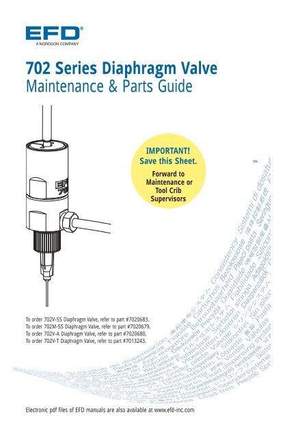
<strong>702</strong> <strong>Series</strong> <strong>Diaphragm</strong> <strong>Valve</strong><br />
<strong>Maintenance</strong> & <strong>Parts</strong> <strong>Guide</strong><br />
To order <strong>702</strong>V-SS <strong>Diaphragm</strong> <strong>Valve</strong>, refer to part #<strong>702</strong>0683.<br />
To order <strong>702</strong>M-SS <strong>Diaphragm</strong> <strong>Valve</strong>, refer to part #<strong>702</strong>0679.<br />
To order <strong>702</strong>V-A <strong>Diaphragm</strong> <strong>Valve</strong>, refer to part #<strong>702</strong>0680.<br />
To order <strong>702</strong>V-T <strong>Diaphragm</strong> <strong>Valve</strong>, refer to part #7013243.<br />
IMPORTANT!<br />
Save this Sheet.<br />
Forward to<br />
<strong>Maintenance</strong> or<br />
Tool Crib<br />
Supervisors<br />
Electronic pdf files of <strong>EFD</strong> manuals are also available at www.efd-inc.com
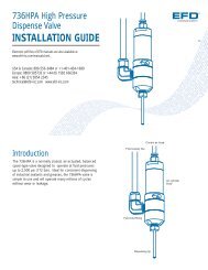
<strong>Valve</strong> Disassembly<br />
and Reassembly Procedures<br />
Fluid Body<br />
1. Remove the fluid body from air<br />
cylinder by turning counterclockwise<br />
until free.<br />
The diaphragm may loosen or<br />
become unthreaded from the<br />
piston rod when the fluid body is<br />
removed. If so, retighten or<br />
reinstall the diaphragm before<br />
reinstalling the fluid body.<br />
2. To reinstall fluid body, turn<br />
clockwise onto air cylinder and<br />
torque to 8.1 – 10.8 Nm (6-8<br />
foot pounds).<br />
To order <strong>702</strong>V-SS <strong>Diaphragm</strong> <strong>Valve</strong>, refer to part #<strong>702</strong>0683.<br />
To order <strong>702</strong>M-SS <strong>Diaphragm</strong> <strong>Valve</strong>, refer to part #<strong>702</strong>0679.<br />
To order <strong>702</strong>V-A <strong>Diaphragm</strong> <strong>Valve</strong>, refer to part #<strong>702</strong>0680.<br />
To order <strong>702</strong>V-T <strong>Diaphragm</strong> <strong>Valve</strong>, refer to part #7013243.<br />
Fitting #<strong>702</strong>0671 for <strong>702</strong>V-SS;<br />
optional for <strong>702</strong>M-SS model<br />
Tip retaining nut<br />
#<strong>702</strong>1194<br />
Specify #<strong>702</strong>1200<br />
for all-metal tips<br />
1<br />
3<br />
8<br />
Fluid body<br />
#<strong>702</strong>0652<br />
7<br />
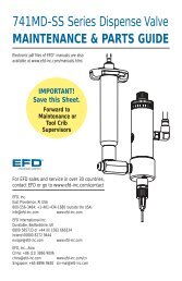
<strong>Diaphragm</strong><br />
3. Remove fluid body by<br />
unscrewing counterclockwise.<br />
4. Place a small Allen wrench into<br />
throughhole located on piston<br />
barb. Hold Allen wrench to<br />
prevent piston from rotating.<br />
5. Unscrew diaphragm by turning<br />
counterclockwise and remove<br />
from the piston rod.<br />
6. Thread on the new diaphragm<br />
holding Allen wrench to prevent<br />
piston from rotating. Tighten<br />
slowly until diaphragm bottoms<br />
against piston rod.<br />
7. Reinstall fluid body, turning<br />
clockwise onto air cylinder and<br />
torque to value specified in step 2.<br />
Important Note: for PTFE Teflon ®<br />
diaphragm - adjust stroke 1/2 turn<br />
open or less. Stroke settings<br />
greater than 1/2 turn dramatically<br />
reduces diaphragm life.<br />
5<br />
2<br />
<strong>Diaphragm</strong><br />
#<strong>702</strong>0660<br />
UHMW PTFE<br />
#7013242<br />
Air cylinder body<br />
#<strong>702</strong>0654<br />
6<br />
O-r<br />
O-ring<br />
#<strong>702</strong>1335<br />
www.efd-inc.com info@efd-inc.com USA & Canada 800-556-3484 Europe +44 (0) 1582 666334 Asia +86 (21) 3866 9006<br />
Sales and service of <strong>EFD</strong> dispensing systems are available worldwide.
335<br />
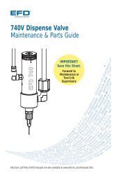
Piston O-ring and Cylinder<br />
8. Remove fluid body and diaphragm.<br />
9. Remove stroke control and spring by<br />
turning counterclockwise.<br />
10. Remove the piston retainer ring.<br />
11. Remove the piston.<br />
12. Remove the cylinder O-ring retaining<br />
ring, washer and O-ring from inside<br />
the air cylinder.<br />
13. Lubricate O-ring, pisiton shaft and air<br />
cylinder wall with Nye Lubricant #865.<br />
(#<strong>702</strong>3234)<br />
14. Reinstall components in reverse order.<br />
O-ring washer #<strong>702</strong>1401<br />
Retaining ring #<strong>702</strong>1482<br />
Piston & rod includes<br />
O-ring #<strong>702</strong>0656<br />
13<br />
4<br />
11<br />
Piston O-ring<br />
#7018529<br />
10<br />
Piston<br />
spring<br />
#<strong>702</strong>0667<br />
Piston retainer<br />
ring #<strong>702</strong>0665<br />
Tools required:<br />
6" adjustable wrench (2)<br />
6" needle-nose pliers<br />
snap-ring pliers<br />
tamper-resist stroke key<br />
(#<strong>702</strong>0663)<br />
O-ring #7018529<br />
9<br />
14<br />
Tamper-resist<br />
stroke control #<strong>702</strong>0658<br />
Tamper-resist<br />
stroke control key<br />
#<strong>702</strong>0663<br />
www.efd-inc.com info@efd-inc.com USA & Canada 800-556-3484 Europe +44 (0) 1582 666334 Asia +86 (21) 3866 9006<br />
Sales and service of <strong>EFD</strong> dispensing systems are available worldwide.
Troubleshooting <strong>Guide</strong><br />
No fluid flow<br />
• If valve operating air pressure is too low,<br />
the valve will not open. Increase air<br />
pressure to 70 psi (4.8 bar) minimum.<br />
• The reservoir air pressure may not be<br />
high enough. Increase pressure.<br />
• The dispensing tip may be clogged.<br />
Replace tip.<br />
• The stroke adjustment may be closed.<br />
Open stroke adjustment.<br />
• Fluid may have solidified in the valve.<br />
Clean the fluid body.<br />
Fluid drools after the valve<br />
closes, eventually stopping<br />
• This is caused when air is trapped in<br />
the outlet section of the fluid body or<br />
the fluid has entrapped air. The air will<br />
expand after the valve closes, causing<br />
extrusion until the air reaches<br />
atmospheric pressure.<br />
Purge the valve by dispensing at a steady<br />
flow until clear. If a small tip is used, it<br />
may be necessary to remove the tip while<br />
purging to obtain sufficient flow to carry<br />
the air down through the tip adapter.<br />
• If the fluid has entrapped air, the material<br />
must be degassed before dispensing.<br />
Fluid drips at a steady rate after<br />
the valve closes<br />
• A steady drip can be caused by excessive<br />
reservoir pressure. Check to be sure<br />
the reservoir pressure is not above 70<br />
psi (4.8 bar).<br />
• If the stroke adjustment knob is turned<br />
out more than two full turns, the<br />
reservoir pressure will force the<br />
diaphragm open. Check the stroke<br />
adjustment knob to be sure it is less<br />
than two turns out.<br />
• A steady drip also indicates failure of the<br />
diaphragm to close fully due to particle<br />
build-up or wear. In either case, replace<br />
the sealing head in accordance with the<br />
maintenance instructions.<br />
Fluid leaks out between fluid<br />
body and diaphragm<br />
• Fluid leakage between the fluid body and<br />
the diaphragm indicates the fluid body is<br />
loose. Torque to proper specifications.<br />
Fluid flows out of the drain hole<br />
• Fluid flowing out of the drain hole<br />
indicates a ruptured diaphragm.<br />
Replace in accordance with the<br />
maintenance instructions.<br />
• If using PTFE Teflon ® diaphragm, verify<br />
stroke setting is 1/2 turn open or less.<br />
Greater than 1/2 turn open reduces<br />
diaphragm life.<br />
<strong>Valve</strong> responds slowly when<br />
opening and closing<br />
• <strong>Valve</strong> response is related to control air<br />
hose length and size. The <strong>702</strong>V model<br />
valve is supplied with 5-feet of 3/32" ID<br />
tubing attached. Any additional length<br />
or size change will affect response time.<br />
Check to be sure the length and size<br />
have not been changed.<br />
Inconsistent deposits<br />
• Inconsistent deposits can result if the air<br />
pressure controlling the valve and/or<br />
supplying the reservoir is fluctuating or if<br />
the valve operating pressure is less than<br />
70 psi (4.8 bar). Check to be sure air<br />
pressures are constant and the valve<br />
operating pressure is 70 psi (4.8 bar).<br />
• The time the valve is open must be<br />
constant. Check to be sure the valve<br />
controller is providing a consistent output.<br />
A NORDSON COMPANY<br />
®<br />
Asia: +86 (21) 3866 9006<br />
Europe: 0800 585733 or +44 (0) 1582 666334<br />
USA & Canada: 800-556-3484 or +1-401-431-7000<br />
technical@efd-inc.com www.efd-inc.com<br />
The Wave Design is a trademark of Nordson Corporation.<br />
©2009 Nordson Corporation <strong>702</strong>-MAINT-01 (SAP#) <strong>702</strong>0651 v042309