
You also want an ePaper? Increase the reach of your titles
YUMPU automatically turns print PDFs into web optimized ePapers that Google loves.
WELCOME TO THE<br />
HOBIE WAY OF LIFE<br />
Congratulations on the purchase of your new HOBIE <strong>18</strong>’ and welcome to the HOBIE® sailing family. The HOBIE <strong>18</strong> cannot be<br />
outgrown. A single adult can sail it at top performance - and a crew of four can cruise in comfort.<br />
We offer this manual as a guide to increased safety and enjoyment of your new boat. The purpose of this publication is to<br />
provide easy, simple and accurate instructions on how to get your <strong>Hobie</strong> <strong>18</strong>’ ready for the water. Please read them carefully<br />
and familiarize yourself with the boat and all of the parts spread before you.<br />
Whether you are a new sailor or a veteran of many years, we recommend that you read this thoroughly before your first sail<br />
and TRY IT OUR WAY FIRST! If you are new to sailing, this manual alone is not intended to teach you how to sail. There are<br />
many excellent books, videos and courses on the safe handling of small sailboats. We suggest that you contact your local<br />
sailboat dealer, college or Coast Guard Auxiliary for recommendations.<br />
Watch for overhead wires whenever you are rigging, launching, sailing or trailering with the mast up. CONTACT OF THE<br />
MAST WITH POWER LINES COULD BE FATAL! Be certain that the rigging area and the area that you will be sailing in are<br />
free of overhead power lines. Report any such power lines to your local power authority and sail elsewhere.<br />
We take pride in presenting the <strong>Hobie</strong> <strong>18</strong>’ to you and hope that you'll take as much pride in owning her.<br />
Fair winds and good sailing!
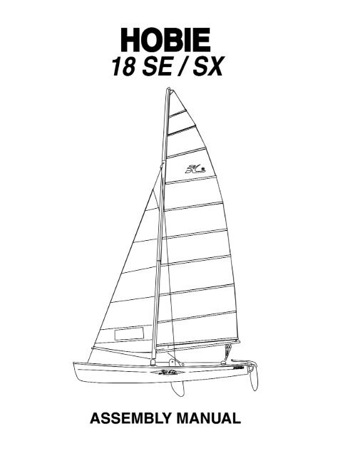
HOBIE <strong>18</strong> AS<strong>SE</strong>MBLY MANUAL<br />
This assembly manual takes you stepby-step<br />
through the setting-up and<br />
sailing of your new HOBIE <strong>18</strong>.<br />
This manual will help you understand<br />
each part in detail.<br />
Note that this manual applies for<br />
both <strong>Hobie</strong> <strong>18</strong> <strong>SE</strong> and <strong>SX</strong> models.<br />
Setting up your HOBIE <strong>18</strong> PAGE<br />
Packaging Layout.................................2<br />
Framing the Hulls .................................3<br />
Installing the Trampoline ...................4-6<br />
Mast Assembly..................................7-8<br />
Stepping the Mast ...........................9-11<br />
Installing the Boom .............................11<br />
Installing the Jib Blocks ......................11<br />
Rudders and Tiller Cross Bar........12-13<br />
Raising the Main Sail ....................14-15<br />
Raising the Jib....................................16<br />
Dagger Boards ...................................17<br />
Illustrations....................................<strong>18</strong>-25<br />
1<br />
Sailing your HOBIE <strong>18</strong>................PAGE<br />
Balancing the boat ...................................26<br />
Steering ....................................................26<br />
Sail power.................................................26<br />
Turning......................................................27<br />
Launching.................................................27<br />
Righting the boat ................................27-28<br />
Docking and landing ................................28<br />
Rudder tuning .....................................28-29<br />
Trailering...................................................29<br />
Maintenance.............................................29<br />
Mooring.....................................................30<br />
<strong>Hobie</strong> Class Associations........................30<br />
Safety tips ..................................Back page
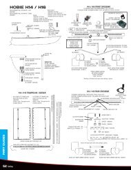
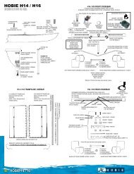
1. Port Hull<br />
2. Starboard Hull<br />
3. Back Bar<br />
4. Boom<br />
5. Tiller Cross Bar<br />
6. Front Bar<br />
7. Battens<br />
8. Rigkit Box #1<br />
9. Rigkit Box # 2<br />
10. Rudders<br />
11. Daggerboards<br />
12. Sail Main and Jib<br />
13. Trampoline<br />
14. Mast (not shown)<br />
See page 25 for descriptions<br />
Packaging Layout<br />
Figure 3<br />
2<br />
<strong>Hobie</strong> <strong>Cat</strong> <strong>18</strong> <strong>SE</strong> Rig Kit Box #1 (fig 2)<br />
Description Quantity<br />
1. Shrouds, Forestay 2,1<br />
2. 7/16” Mainsheet 48’ 1<br />
3. 5/16” Jib Sheet 45’ 1<br />
4. 1/4” Trampoline Lacing - Center 1<br />
5. 1/4” Trampoline Lacing - Aft 2<br />
6. Jib Luff Tensioner 2” 1<br />
7. Jib Halyard Line 20” 1<br />
8. Mainsheet Block Assembly 1<br />
9. Jib Sheet Block 2<br />
10. Jib Furling Assembly w/line 17” 1<br />
Figure 1<br />
Figure 2
Framing the Hulls<br />
(Recommend two people)<br />
Tools-HEX wrench (provided) and a screwdriver with a<br />
1 /4" head.<br />
Retaining Channel 8<br />
Front Bar Inboard Bolt 3 3/4" 2<br />
Front Bar Outboard Bolt 2" 2<br />
Rear Cross Bar Inboard Bolt 2 1/ 2" 2<br />
Rear Cross Bar Outboard Bolt 2" 2<br />
Lock Nuts for 802-359 Outboard Bolts 4<br />
1. Place the boxes on level ground with the seams<br />
facing up. Cut the bands and open the lid. Remove the<br />
sail, trampoline, rig kits, (two boxes), dagger boards,<br />
rudders, and metal work modular packages. See Figure<br />
1.<br />
1. The dagger board and rudder are in cardboard<br />
sleeves on each side of the hull.<br />
2. Leave the hulls in the end pieces so that they will be<br />
supported in the upright position while being framed.<br />
3. Place the hulls 8 feet apart with the metal trampoline<br />
track facing the inside.<br />
4. Place the backbar across the aft saddles with the<br />
traveler at the back.<br />
5. Locate the bar firmly in the saddles and insert the aft<br />
inboard bolt assembly under the port rail. *See Figure 4.<br />
Start the bolt by hand to insure proper engagement. Do<br />
not start the bolt with the hex wrench as you might cross<br />
thread the internal assembly. If the bolt has trouble<br />
advancing into the bar do the following;<br />
Figure 4<br />
a. Rock the hull with quick movements as you turn the<br />
bolt.<br />
b. Double check the bars alignment with the saddle.<br />
c. Have another person lift and lower the bow as you<br />
turn the bolt.<br />
If you are still having trouble advancing the bolt remove<br />
the back bar from the boat and try the bolt in it. Look for<br />
3<br />
metal chips or dirt particles inside the bar which could<br />
be hindering the bolt's progress.<br />
*Port refers to left, starboard refers to right.<br />
IMPORTANT<br />
Read this before framing the hulls.<br />
Prior to inserting each crossbar bolt, (Framing the<br />
hull, step 5), apply approximately 1/8th (about one<br />
teaspoon full) of the tube of silicon sealant around<br />
the unthreaded portion of each bolt. This will seal<br />
the area around each bolt and prevent unwanted<br />
water from entering the hull.<br />
6. Install the aft inboard bolt assembly on the starboard<br />
side as described in step 5. It is important that the hulls<br />
be parallel and level at this time. The frame will be very<br />
difficult to attach to the hulls if they are misaligned.<br />
Once the aft inboard bolts are installed, STOP. Do not<br />
install the outboard bolts. This will be done later.<br />
7. Place the front bar across the forward saddles. The<br />
lengthwise track opening should be facing toward the<br />
bows. See Figure 5.<br />
Figure 5<br />
8. With the bar seated firmly in the saddle insert the<br />
forward inboard bolt assembly under the port rail. The<br />
bolt is fitted into the bar by the same procedure as the<br />
aft bolt assemblies.<br />
9. Install the inboard bolt assembly on the starboard<br />
side of the cross bar. If there are any problems<br />
advancing the bolt refer to instructions in step 5A, B, C.<br />
Once the bolts are engaged, STOP. Do not tighten them<br />
down.
10. The four outboard bolt assemblies are identical. To<br />
install, first slip the bolt through the outer end of the<br />
corner casting and down through the rail of the boat.<br />
Place the stainless steel channel over the bolt's<br />
exposed section which is under the rail. Spin the nylock<br />
nut on the bolt but do not tighten the bolt down at this<br />
time.<br />
11. Install all four outboard bolts in the manner<br />
described in step 10. To insert the bolts in the front<br />
corner castings it will be necessary to remove the cover<br />
plates. Be careful when extracting the cover plate<br />
retaining screw. It is made of aluminum and can be<br />
galled. See Figure 6.<br />
12. Use the hex drive to tighten the bolts. Follow this<br />
order to secure the bolts.<br />
inboard front<br />
inboard aft<br />
outboard aft<br />
outboard front<br />
Port and Starboard<br />
Port and Starboard<br />
Port and Starboard<br />
Port and Starboard<br />
It may be necessary to repeat this sequence more than<br />
once to seat the front and back bars firmly into the<br />
saddles. Once the bolts are tight check the dolphin<br />
striker rod for looseness. If it is loose, tighten the nuts at<br />
either end of the rod where it exits the outboard section<br />
of the corner casting.<br />
13. Replace the cover plates on the front corner<br />
castings. Be careful not to damage the retaining screw<br />
as you are installing it.<br />
14. Re-check the cross bar after five hours of sailing. It<br />
will probably be necessary to tighten some of the bolts.<br />
4<br />
TRAMPOLINE AS<strong>SE</strong>MBLY<br />
1. Install the aft lacing strip. Feed the lacing strip into<br />
the rear cross bar at the right just inside the hull where<br />
the track has been cut away. See Figure 7. Center it<br />
on the rear cross bar.<br />
2. Lay the trampoline halves face down forward of the<br />
front cross bar and between the hulls. The long row of<br />
grommets should be on the inside and the short row of<br />
grommets will be up at the bow. See Figure 8<br />
3. With the port trampoline half still face down, lead the<br />
short side (without grommets) into the front cross bar at<br />
the opening in the center of the bar and slide it over to<br />
the hull. See Figure 9<br />
4. Pass the trampoline between the front cross bar and<br />
the dolphin striker so that it is covering the bottom of the<br />
cross bar.<br />
Figure 7<br />
Figure 6
5<br />
Figure 8<br />
Figure 9
5. Insert the aft outboard corner of the trampoline into<br />
the extrusion on the inside of the hull and pull the<br />
trampoline as far aft as it will go.<br />
6. Repeat steps 2-5 for installing the starboard<br />
trampoline.<br />
7. In front of the rear cross bar there is a hole in either<br />
inboard rail. Insert the port aft lacing line into this hole<br />
on the port hull and exit it straight down. Tie a knot in<br />
the tail of the line and then pull the knot up under the<br />
rail.<br />
8. Thread the lacing line from the inboard rail to the<br />
corner grommet on the AFT lacing strip and then to the<br />
corner grommet on the port trampoline. Temporarily tie<br />
the line off to the rear cross bar.<br />
9. Repeat this procedure for the starboard side of the<br />
trampoline.<br />
10. Attach the center trampoline lacing line to the<br />
forward-most grommet on the starboard trampoline.<br />
Lace it down to the rear taking out the slack as you go.<br />
11. Untie the aft lacing lines and complete the lacing<br />
starting at the outboard side and working toward the<br />
center. See Figure 10. With use the trampoline will<br />
stretch and require periodic re-tightening.<br />
6<br />
Figure 10<br />
Figure 11
MAST AS<strong>SE</strong>MBLY<br />
1. Support mast at both ends on saw horses or other<br />
such devices. Ref: Illus. #1, Pg. 20.<br />
2. Spreaders. In the rig kit you will find all the parts of<br />
the spreader assembly.<br />
3. The larger of the two pairs of aluminum rods (1-1), is<br />
the spreader arm. Attach it to the aft tab of the spreader<br />
root (1-2). Use a 3/16" x 11/16" clevis pin (1-3).<br />
turnbuckle on the bolt, pass the bolt through the mast at<br />
the compression sleeve which is located 1 foot above<br />
the mast base(1-14). The shackled end of the MRCY<br />
should be behind the mast.<br />
4. Locate the slide (1-4) on the spreader arm so that the<br />
large wing of the slide is closest to the mast, and facing<br />
forward.<br />
5. Line up the inboard hole on the slide with the<br />
outboard hole on the spreader arm and insert the slide<br />
adjustment pin 3/16" x 13/16" (1-5). The slide is now<br />
positioned in the raked forward attitude.<br />
6. Connect the smaller brace rod (1-6) between the<br />
forward tab on the spreader root and the wing on the<br />
slide, with the brace pin 3/16" x 9/16" (1-7).<br />
7. Secure all the clevis pins with the cotter keys<br />
provided.<br />
8. Repeat steps 3-7 for the opposite side of the mast.<br />
9.There will be two large cotter pins (1-8) left over, place<br />
them to one side, they will be used later to retain the<br />
diamond wires in the spreader arm tips.<br />
10. Mast rotation control yoke (MRCY). In the rig kit you<br />
will find the parts of the MRCY. You will also need the<br />
diamond wires which can be identified by the<br />
turnbuckles on one end.<br />
11. IMPORTANT follow this sequence to assemble the<br />
MRCY and diamond wires.<br />
12. Hold the two arms of the<br />
yoke (1-9) together at the<br />
ends with the small holes.<br />
Attach the small block (1-10)<br />
and shackle (1-11) to this<br />
end, see Figure 12. (There is<br />
a short line packed with the<br />
MRCY, set it to one side for<br />
now.)<br />
13. Pass the long bolt (1-12)<br />
Figure 12<br />
7<br />
NOTE: The style of rotator yoke shown in<br />
Figure 12 is the older mast rotator style.<br />
Current models do not have a pulley. See page<br />
20 for details on the new style.<br />
through the large hole in one arm of the MRCY (1-9).<br />
Slide the toggle of diamond wire turnbuckle (1-13) over<br />
the bolt and move it next to the MRCY arm.<br />
14. With one arm of the MRCY and one diamond wire<br />
turnbuckle on the bolt, pass the bolt through the mast at<br />
the compression sleeve which is located 1 foot above<br />
the mast base( 1-14). The shackled end of the MRCY<br />
should be behind the mast.<br />
15. Slide the turnbuckle toggle of the opposite diamond<br />
wire over the exposed portion of the bolt. Install the<br />
remaining arm of the MRCY on top of the turnbuckle<br />
toggle.<br />
16. Put the retaining nut (1-15) on the exposed threads<br />
of the bolt and finger tighten only. It will be tightened<br />
later. See figure 13.<br />
17. Loosen the lock nuts at each end of the turnbuckle<br />
body and expand the turnbuckle 2-1/2". Note that both<br />
lock nuts spin in the same direction to unlock.<br />
<strong>18</strong>. Attach the opposite end of the diamond wire to the<br />
diamond wire tang (1-16) which is located 2 feet below<br />
the mast tang (1-17). Install clevis pins (1-19) and cotter<br />
pins (1-20).<br />
Figure 13
19. Slip the port diamond wire into the tip of the port<br />
spreader arm. Make sure that the anti-chafing roller on<br />
the diamond wire is above the spreader tip. Secure the<br />
diamond wire by installing one of the long cotter pins (1-<br />
8) through the tip of the spreader.<br />
20. Repeat this procedure for the starboard diamond<br />
wire.<br />
21. Tighten the nut (1-15) of the through mast bolt which<br />
is at the lower end of the diamond wires.<br />
22. Tighten the diamond wires by rotating the turnbuckle<br />
bodies. The turnbuckles must be adjusted equally since<br />
over-tightening one side will induce a bend into the<br />
mast. See Figure 14.<br />
Figure 14<br />
WARNING<br />
The diamond wire adjustment not only affects boat<br />
performance but also affects the mast structural<br />
integrity. If the diamond wires are loose or broken<br />
the mast will be permanently distorted or could fail<br />
completely. The diamond wires cannot be tightened<br />
sufficiently by hand. It will require the assistance of<br />
a wrench to make the last two or three revolutions<br />
of the turnbuckle body. Additionally, the diamond<br />
wire will stretch with use and require periodic<br />
inspection and re-tightening.<br />
23. Once the diamond wires are adjusted, spin the<br />
locknuts up against the turnbuckle body tight. You can<br />
do this by hand.<br />
24. Tie a piece of string through one turnbuckle body<br />
and over through the other turnbuckle body. This will<br />
keep the turnbuckle from unscrewing.<br />
8<br />
25. Locate the shrouds and forestay in the rig kit. They<br />
are packed together and are the only rigging which is<br />
vinyl coated. The three wires are already attached to a<br />
large shackle. Remove the pin from the shackle and<br />
attach it to the mast tang (1-17) at the lowest of the.<br />
holes in the tang. See Figure 15. Secure the safety wire,<br />
which is attached to the thumbscrew, to the shackle<br />
body. This will keep the pin from unscrewing.<br />
26. The double trapeze wire has a single thimble at its<br />
upper end. Engage this thimble to the shackle on the<br />
opposite set of trapeze wires after you have inserted the<br />
shackle through the upper set of holes in the mast tang.<br />
See Figure 15.<br />
Figure 15
STEPPING THE MAST.<br />
DANGER - Do not attempt to step the mast in an<br />
area of low overhead wires. A mast contacting an<br />
electrical wire could be fatal.<br />
1. Secure the four trapeze wires near the bottom of the<br />
mast so that they will be out of the way while the mast is<br />
being raised.<br />
2. Attach the jib halyard line to each end of the jib<br />
halyard wire to form a very large loop. Tie the line<br />
around the fork at the bottom of the forestay. The<br />
halyard line must be connected to the wire before the<br />
mast is raised or you will be unable to hoist the jib later.<br />
See Illustration.<br />
3. Carry the mast over to the boat and place the hinge<br />
of the mast base over the mast step which is located on<br />
the front bar, see Figure 17. The sail track should be<br />
facing down. Note: when lowering the mast over the<br />
trampoline be sure to guide the mast rotation control<br />
yoke between the trampoline halves.<br />
9<br />
Jib Halyard Wire<br />
Luff Tensioner<br />
Jib Halyard Line<br />
Figure 16<br />
Figure 17
4. With the hinge in place over the step insert the mast<br />
step pin through the entire assembly so that it is visible<br />
on the opposite side on the hinge.<br />
5. Attach the bridle wires to the bow tangs. Attach the<br />
roller furler mechanism between the bridle wires. Make<br />
sure the oblong hole<br />
in the roller furler is<br />
aft. See Figure <strong>18</strong>.<br />
6. Attach the port<br />
shroud to the port<br />
stay adjuster and the<br />
starboard shroud to<br />
the starboard stay<br />
adjuster. Secure the<br />
shrouds to the top<br />
hole in the stay<br />
adjuster at this time.<br />
See Figure 19.<br />
7. Secure the base<br />
of the stay adjuster<br />
to the anchor pin on<br />
the respective hull.<br />
Figure <strong>18</strong><br />
Figure 19<br />
10<br />
CAUTION:<br />
We recommend two people for stepping the mast. It<br />
is heavy for one person and could slip causing<br />
injury or damage.<br />
8. Stand on the trampoline next to the back bar and<br />
raise the mast to your shoulders. Make sure the shrouds<br />
are not fouled and the stay adjusters are free before<br />
advancing further. Do not raise the mast in an area with<br />
any overhead wires. If everything is clear walk straight<br />
ahead raising the mast as you go. See Figures 20, 21,<br />
and 22.<br />
9. Once the mast is in the vertical position lean your<br />
weight against the<br />
mast to hold it in<br />
place. The second<br />
person can now let<br />
go of the mast and<br />
attach the forestay<br />
to the top of the<br />
stay adjuster which<br />
extends from the<br />
roller furler<br />
assembly. See<br />
Figure <strong>18</strong>.<br />
Figure 20<br />
10. Remove the<br />
mast step pin only<br />
after the forestay<br />
has been secured.<br />
Store the pin in the<br />
pouch on the<br />
trampoline.<br />
11. Once the mast<br />
has been raised<br />
untie the trapeze<br />
wires. In the rig kit<br />
you will find a bag<br />
which contains 4<br />
trapeze dogbones,<br />
4 rope locks and 4<br />
trapeze adjusting<br />
lines.<br />
12. Tie the<br />
adjusting line onto<br />
one of the<br />
shockcord loops<br />
which is located at<br />
the outside rail<br />
adjacent to the stay<br />
adjuster.<br />
Figure 21<br />
Figure 22
13. Lace it through the rope lock and then through the<br />
thimble at the end of the trapeze wire. Now tie the line<br />
onto either end of the dogbone. See Figure 23.<br />
14. Repeat this process for the other three trapeze wires<br />
at the respective locations.<br />
Figure 23<br />
BOOM INSTALLATION<br />
1. Attach the gooseneck pin which extends from the<br />
front of the boom to the gooseneck yoke on the mast.<br />
See Figure 24.<br />
2. Tie the line which was packed with the mast rotation<br />
control yoke to the forward-most jam cleat on the boom.<br />
See step 11 of mast assembly. Run the line through the<br />
11<br />
block on the end of the mast rotation control yoke and<br />
then feed it through the jam cleat. Tie a knot<br />
in the end of the line so that it will not slip back through<br />
the jam cleat.<br />
See Figure 35.<br />
Once again, be sure to note that this is the older<br />
style of mast rotator. With the newer style, the line<br />
does not run through a pulley, but through a ring at<br />
the end of the control yoke. Run the line through<br />
the ring and into the jam cleat.<br />
JIB BLOCK INSTALLATION<br />
1. The large jib blocks are packed in the rig kits.<br />
Remove the jib track end stop on the jib track and slide<br />
the car on the bottom of the block into the track. See<br />
Figure 25. Note that the slide adjustment knob is aft of<br />
the block assembly.<br />
Figure 25<br />
Figure 24
<strong>Hobie</strong> <strong>18</strong> and <strong>SX</strong><strong>18</strong> UPDATES<br />
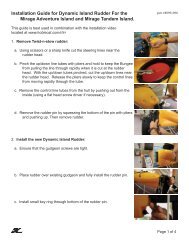
INSTALLING THE RUDDER AS<strong>SE</strong>MBLY<br />
The rudders were updated after 1987. The newer<br />
rudders use a black plastic cam to lock the rudder in the<br />
down position. Locate the left and right rudder<br />
assemblies. The left one has a red dot and the right one<br />
a green dot. The tiller arms should have a slight bow<br />
towards the centerline of the boat.<br />
As shown in the original instructions, position the<br />
rudders at the transom. There are two bushings and two<br />
washers provided with the each new assembly. Slide<br />
the bushings in from the bottom and place the longer<br />
one in the lower casting hole. Install a cotter key in each<br />
rudder pin. Assemble as shown below. Then insert the<br />
remaining cotter keys in the top of the rudder pins to<br />
hold the rudders in place.<br />
INSTALLING THE TILLER CONNECTOR<br />
The tiller arms have swivels on the ends. Point the<br />
connector rods upwards and slide the tiller connector<br />
end fitting over the rods. Place the adjustable end of<br />
the connector rod to the port (left) side of the boat. Pull<br />
the small tabs forward and over the rod and lock them in<br />
the slots. Rudder toe-in adjustments can be made with<br />
the threaded end fitting on the tiller cross bar. Typical<br />
adjustment has rudders in parallel.<br />
Figure 27<br />
Figure 26<br />
12<br />
INSTALLING THE SAIL BATTENS<br />
Unfold the sail and lay it out on the trampoline. There<br />
will be a small bundle of thin lines tied to the top of the<br />
sail. These are the batten tension lines. Tie the batten<br />
tension lines to one of the small grommets at the end of<br />
each batten pocket as diagramed in figure 28 (one to<br />
each batten pocket). Tie the lines using a bowline knot<br />
Figure 28<br />
as found in the "knots" diagramed on page 4. It is best<br />
to tie the lines all to one side of the sail. Insert each<br />
batten (shortest batten at the top to longest batten at the<br />
bottom of the sail).<br />
Note that the batten ends have a "V" jam cleat<br />
molded into them. These "V" jam cleats will keep<br />
the tension line from slipping in only one direction.<br />
Note the hollowed-out side of the cleats. Pull the<br />
line from the flush side toward the hollowed side.<br />
The upper batten is narrower and has a different cleat<br />
shape. To be sure this cleat works correctly, position it<br />
so that the hollowed out side of the cap faces the<br />
bowline that you have tied to the sail grommet. Position<br />
the larger caps so that the hollowed sides face away<br />
from each knot.<br />
Following the diagram in figure 28, lace the tension lines<br />
through each batten end cap. Pass the line through the<br />
hole in the cap, then through the grommet on the<br />
opposite side. For the smaller caps, pass the line over<br />
the "V' cleat, pull tension forcing the batten into the<br />
pocket, then pull the line into the cleat to hold it. For the<br />
larger caps, pass the line through the second hole in the<br />
cap, then pass the line through the first grommet and<br />
back to the "V" cleat. Pull tension on the line forcing the<br />
batten into the pocket and cleat it. Tie a small figure 8<br />
knot in the end 1 of each line to prevent the battens<br />
from falling from the sail if the line releases from the<br />
cleat. Tension each batten so that the batten is well<br />
seated and the wrinkles in the batten pockets are<br />
removed. Excessive batten tension will cause the sail to<br />
be more difficult to handle.
RUDDER AND TILLER CROSS BAR<br />
INSTALLATION (Pre 1987 boats)<br />
1. Disengage the tiller arm from the lower casting and<br />
lock the tiller arm and rudder in the kicked up position.<br />
This will pull the rudder blade up and out of the way so<br />
the rudder pin can be installed.<br />
2. Hold the lower casting up to the transom of the boat<br />
and fit the casting over the gudgeons. Slide the rudder<br />
pin up through the casting and gudgeons with the hole<br />
in the rudder pin closest the bottom. Once the hole in<br />
the pin is above the casting at the lower gudgeon, stop<br />
and insert the cotter key which is packed with the rudder<br />
pins. Bend over the legs of the key to secure it in place.<br />
The rudder can be lowered now. See Figure 29 and 30.<br />
Figure 29<br />
Figure 30<br />
13<br />
3. To distinguish the port rudder from the starboard<br />
rudder, the port rudder arm will bend toward the center<br />
of the boat when on the port hull.<br />
4. Attach the tiller cross bar to the tiller arm as shown in<br />
figure 31.<br />
Figure 31<br />
Figure 32
RAISING THE SAILS<br />
1. Point the boat into the wind before you begin this<br />
operation.<br />
2. Lay the main sail out on the trampoline. Insert the<br />
battens into the batten pockets starting at the top of the<br />
sail and working your way down. The batten has a tip on<br />
each end. The end without any holes goes into the sail<br />
first. Slip the batten in until it seats into the batten<br />
pocket protector at the leading edge of the sail.<br />
3. Thread the batten tie through the aft batten tip and<br />
the sail as shown in Figure 33. Secure the end of the<br />
batten ties with a figure eight knot.<br />
Figure 33<br />
4. Attach the twist shackle on the end of the main<br />
halyard to the grommet in the headboard and feed the<br />
sail into the sailtrack in the mast. See Figure 34. Note<br />
the metal ring connected to the twist shackle. It will<br />
engage the latching mechanism at the top of the mast.<br />
(see Figure 34a). Continue to raise the sail by pulling<br />
the main halyard out from the base of the mast.<br />
5. It is recommended that you lubricate the leading edge<br />
of the sail with paraffin from time to time to reduce wear<br />
from the sail track. It will also make it easier to raise the<br />
sail.<br />
6. Raise the sail until the metal ring above the halyard<br />
shackle engages the halyard hook at the top of the<br />
mast. Store the excess halyard line in the pouch on the<br />
trampoline.<br />
7. Tie the downhaul line to the tack of the sail and lace<br />
the downhaul as shown in Figure 35.<br />
8. Attach the outhaul car on the boom to the clew of the<br />
main. See Figure 36.<br />
9. To lower the main, untie the downhaul and slide the<br />
leading edge of the sail up the sailtrack a few inches.<br />
Next pull hard on the main halyard and the metal ring<br />
and the top of the sail will overrun the halyard hook,<br />
rotate the mast to the starboard then release the<br />
halyard.<br />
14<br />
Figure 34<br />
Figure 34a
10. Attach the three boom blocks to the hangers on the<br />
boom. Secure the ratchet block to the top of the traveler<br />
car. Thread the mainsheet through the blocks as shown<br />
in Figure 37. Slip the other end of the mainsheet<br />
through the traveler jam cleat, then guide the line<br />
through the center of the traveler, and secure at the<br />
dead eye on the back bar.<br />
11. With only the main sail up tighten the shrouds. First<br />
move the traveler car all the way over to the port side of<br />
the back bar. Next pull the mainsheet in very hard. The<br />
port shroud should be slack now and can be moved<br />
down in the stay adjuster. Repeat this procedure for the<br />
starboard shroud. Note: Tension on the shrouds must<br />
be relieved before lowering the main sail. If you intend<br />
to unstep the mast.<br />
Figure 36<br />
15<br />
Note: Old style mast rotator shown here.<br />
H<strong>18</strong><strong>SX</strong> Downhaul Instructions<br />
Figure 35<br />
1. Using the twist shackle, attach the double block to the<br />
sail luff grommet.<br />
2. Tie off the downhaul line (10' of 3 /16" yt braid) to the<br />
sail luff grommet.<br />
3. Run the line through the cheek block on the left hand<br />
side of the gooseneck yoke.<br />
4. Continue to the double block, then to the cheek block<br />
on the right hand side of the gooseneck yoke, then back<br />
through the second sheave on the double block.<br />
5. Tie off on mast downhaul cleat located below the<br />
boom.<br />
Figure 37
Raising the Jib<br />
1. Attach the shackle on the end of the jib halyard wire<br />
to the head of the jib.<br />
2. Wrap the luff pocket of the jib around the forestay and<br />
engage the zipper an inch or so. Next thread the jib<br />
halyard line inside the luff pocket. See Figure 38.<br />
Figure 38<br />
3. Raise the sail by pulling on the jib halyard line and at<br />
the same time advance the zipper down the luff until the<br />
jib tack is even with the roller furling housing.<br />
4. Attach the jib tack to the shackle on the neck of the<br />
roller furling housing. .<br />
5. Untie the jib halyard line and connect the luff<br />
tensioner to the block on the end of the jib halyard.<br />
Thread the tensioner down through the tack shackle,<br />
then back up through the block on the jib halyard.<br />
Secure the line in the jam cleat on the sail. See Figure<br />
39.<br />
6. IMPORTANT. Only apply the jib luff tension after the<br />
shrouds and forestay have been tightened. To do so<br />
beforehand could result in the jib halyard being broken<br />
when the slack in the shrouds is taken up.<br />
7. Attach the jib clew blocks to the jib clew, see Figure<br />
40.<br />
8. Thread the jib sheet through the port jib block, then<br />
around the jib clew block. Take the line back and tie it<br />
off at the becket on the jib block. See Figure 41.<br />
16<br />
9. Thread the remaining portion of the jib sheet through<br />
the starboard jib block in this same fashion.<br />
10. The roller furler line can be temporarily secured in<br />
the jam cleat on the back side of the front cross bar.<br />
Roller furler line adjustment on<br />
take up spool.<br />
a. Disconnect jib clew blocks<br />
from jib clew.<br />
b. Pullout the roller furler line<br />
from the housing until the take<br />
up spool is empty and secure the<br />
line to the cleat on the front bar.<br />
c. Wrap the sail clockwise<br />
around the forestay until it is<br />
completely furled.<br />
d. Reattach the jib clew blocks to<br />
the jib clew. The jib is now in the<br />
furled position.<br />
To unfurl the jib, release the<br />
roller furler line which is cleated<br />
on the front bar, and pull on the<br />
jib sheet.<br />
Figure 39<br />
Figure 40<br />
Figure 41<br />
To furl the jib, release the jib sheet (both port and<br />
starboard) pull the furler line until the jib is completely<br />
furled. Do not partially furl the sail, this will cause<br />
uneven stretching of the exposed sail.
DAGGER BOARDS<br />
1. Slip the shock cord through the hole in the upper<br />
portion of the dagger board, take both ends to the hole<br />
on the out board deck flange. Pass both ends through<br />
the hold and tie a knot under the rail.<br />
2. Pass the rope handle through the same hole in the<br />
dagger board as before. Tie the two ends together to<br />
form a large loop which will serve as the handle. See<br />
Figure 42.<br />
17<br />
Figure 42<br />
3. When raising or lowering the board do not rock it fore<br />
and aft. This will cause damage to the trailing edge. Pull<br />
the leading edge of the dagger board aft about 1/4 of an<br />
inch so that it is not contacting the lip of the deck and it<br />
can be easily moved up and down.<br />
4. IMPORTANT. If you expect contact with an object or<br />
the shore, pull the dagger boards up out of the way.<br />
Severe damage can resuIt if the boards contact any<br />
solid object regardless of the speed.
HOBIE CAT CAT<br />
<strong>18</strong>’ <strong>18</strong><br />
<strong>18</strong>
INDEX<br />
NO. DESCRIPTION<br />
1 Arm<br />
2 Brace<br />
3 Slide<br />
4 Diamond Wire (one side)<br />
5 Gooseneck Yoke<br />
6 Check Block<br />
7 Mast Rotation Line<br />
8 Modified Swivel Block<br />
9 Shackle<br />
10 Mast Rotation Assembly<br />
11 Pin-Pawl Bearing, 5.5.<br />
12 Ring-Halyard Line<br />
13 Hook for Halyard Lock Assembly<br />
14 Jib Furling Assembly<br />
15 Bridle Wire Assembly<br />
16 Screw - 5.5. (1/4 x 20)<br />
17 Back Up Plate - Bow Tang<br />
<strong>18</strong> Nylock Nut (1/4 x 20)<br />
19 Mast Tang<br />
20 Trapeze Wire (one side)<br />
21 Shackle<br />
22 Shroud<br />
23 Pigtail with Swivel<br />
24 Jib Halyard Block Assembly<br />
25 Clevis Pin<br />
26 Mast Hinge Casting<br />
27 Mast Base Casting<br />
28 Screw RD. HD. 1/4 x 20<br />
29 Star Lock Washer<br />
30 Sheave<br />
31 Clevis Pin<br />
32 Washer<br />
33 Bushing<br />
34 Pad. Mast step<br />
35 Mast Step<br />
36 Rivet<br />
37 Left Front Corner Casting<br />
38 Boom Outhaul Slide Assy.<br />
39 Cotter Key<br />
40 Outhaul Car<br />
41 Clevis Pin<br />
42 Sheave<br />
19<br />
43 Rollers<br />
44 Pin<br />
45 Outhaul Line<br />
46 Boom<br />
47 Boom Block<br />
48 Single Block with Becket<br />
49 Boom Block<br />
50 Main Sheet Line<br />
51 Triple Block<br />
52 Left Rear Corner Casting<br />
53 H-<strong>18</strong> Ratchet Block<br />
54 Traveler Assembly<br />
55 Channel<br />
56 Bushing<br />
57 Bolt 3/8 x 16 - 3 (rear only)<br />
58 Swivel Main Sheet Fairlead<br />
59 Rear Crossbar<br />
60 Tiller Crossbar with Rudder Adjuster<br />
61 Tiller Arm Bent<br />
62 Upper Rudder Arm Right/Starboard<br />
63 Right Rear Corner Casting<br />
64 Channel<br />
65 Nylock Nut - versus drawing<br />
66 Upper Rudder Casting<br />
67 Lower Rudder Casting - bare<br />
68 Rudder Pin<br />
69 Lower Gudgeon<br />
70 Jib Sheet Line<br />
71 Jib Sheet Block<br />
72 Front Crossbar Assembly<br />
73 Right Front Corner Casting<br />
74 Bolt - Cover Plate<br />
75 Flange<br />
76 Storage Cover w/Handle
Old Style Yoke<br />
1-1 Spreader Arm<br />
1-2 Spreader Root<br />
1-3 Clevis Pin 3/16" x 11/16"<br />
1-4 Slide<br />
1-5 Clevis Pin 3/16" x 13/16"<br />
1-6 Brace<br />
1-7 Clevis Pin 3/16" x 9/16"<br />
1-8 Cotter Pin<br />
1-9 Mast Rotation Control Yoke<br />
1-10 Block<br />
1-11 Shackle<br />
1-12 Bolt 4-1/8" Lg.<br />
1-13 Diamond Wire<br />
1-14 Mast Base Assembly<br />
1-15 Nut Nylock<br />
1-16 Diamond Wire Tang<br />
1-17 Mast Tang<br />
1-<strong>18</strong> Mast Extrusion<br />
1-19 Clevis Pin 3/16" x 1/2"<br />
1-20 Cotter Pin<br />
Illustration No. 1<br />
Mast Assembly<br />
20<br />
New Style Yoke
21<br />
2-1 Jib Block Housing<br />
2-2 Jib Halyard Wire<br />
2-3 Luff Tensioner<br />
2-4 Jib Halyard Line<br />
2-5 Jib Block Sheave<br />
2-7 Clevis Pin<br />
2-8 A Cotter Pin<br />
2-9 Swedge<br />
2-10 Thimble<br />
2-11 Block<br />
2-12 Shackle<br />
3-1 Bolt<br />
3-2 Half Ball<br />
3-3 Tiller Crossbar<br />
3-4 Plastic Washer<br />
3-5 Tiller Arm<br />
3-6 Washer<br />
3-7 Spring<br />
3-8 Nut<br />
Illustration No. 2<br />
Jib Halyard Assembly<br />
Illustration No. 3<br />
Tiller Connector Kit
22<br />
*Rudder system Pre-1987 shown<br />
Illustration No. 6<br />
Rudder Assembly<br />
6-1 Rudder Blade-Drilled<br />
6-2 Lower Rudder Casting Assembly<br />
6-3 Port Upper Rudder Housing Assembly<br />
6-4 Nut Nylock<br />
6-5 Bolt 2" Lg<br />
6-6 Spring<br />
6-7 Delrin Screw<br />
6-8 1 / 4" I.D. Nyliner<br />
6-9 Rudder Cam<br />
6-10 Upper Rudder Housing Casting<br />
6-11 Rivet<br />
6-12 Locking Sleeve<br />
6-13 Pin Upper Rudder Housing<br />
6-14 Pin Lower Rudder Housing<br />
6-15 Tiller End Cap<br />
Illustration No. 7<br />
Outhaul Car Assembly<br />
7-1 Adjuster Pin Retaining Ring<br />
7-2 Outhaul Slide Car<br />
7-3 Clevis Pin 1 /4" x 7 /8"<br />
7-4 Ball Roller Bearing<br />
7-5 Clevis Pin 1 /4" x 5 /8"<br />
7-6 Pin-Bearing<br />
7-7 Sheave<br />
7-8 Cotter Key
23<br />
8-1 1- 1/4" Lg H.H. Bolt<br />
8-2 Deck Plate<br />
8-3 Sheave<br />
8-4 Spacer<br />
8-5 Car Assembly<br />
8-6 Cotter Pin<br />
8-7 H.H. Nuts-Nylock<br />
8-8 Bearing Cylinder<br />
8-9 Pin-Clevis<br />
8-10 Bearing Ball<br />
Illustration No. 8<br />
Traveler Assembly<br />
Illustration No. 9<br />
Roller Furler Assembly<br />
9-1 Upper Retaining Ring<br />
9-2 Top Nyliner<br />
9-3 Bottom Nyliner<br />
9-4 Yoke<br />
9-5 Housing<br />
9-6 Interior Retaining Ring<br />
9-7 Bearing Sleeve<br />
9-8 Bearing Race<br />
9-9 Bearing Cage<br />
9-10 Bearings<br />
9-11 Tube<br />
9-12 Spool<br />
9-13 Screw Truss Head
24<br />
Illustration No. 10<br />
(old style)<br />
Dolphin Post Assembly<br />
10-1 Screw RHMS<br />
10-2 Internal Lock Washer<br />
10-3 Washer<br />
10-4 Mast Step Pad<br />
10-5 Bushing<br />
10-6 Mast Step Casting<br />
10-7 Dolphin Striker Post<br />
10-8 Dolphin Striker Sleeve<br />
Illustration No. 11<br />
(new style)<br />
Dolphin Post Assembly<br />
11-1 Screw RHMS<br />
11-2 Washer<br />
11-3 Bearing<br />
11-4 Mast Step Casting<br />
11-5 Dolphin Striker Post<br />
11-6 Dolphin Striker Sleeve
Parts Relating to Diagram on Page 2<br />
11 Trapeze Seat Assy.<br />
2 Trapeze Seat<br />
2 Trapeze Hook<br />
2 Trapeze Lacing Line 6'<br />
12 Mast Rotation Control Yoke Assy.<br />
2 Mast Rotation Control Yoke<br />
1 Shackle 1 Block<br />
1 Mast Rotation Control Line 3'<br />
1 Mast Rotation Control Yoke Retaining Bolt<br />
1 Retaining Bolt Nut<br />
13 Spreader Assy.<br />
2 Spreader Arm<br />
2 Brace<br />
2 Slide<br />
2 Spreader Arm Root Pin 3/16" x 11/16"<br />
2 Spreader Arm Slide Pin 3/16" x 13/16"<br />
4 Brace Pin 3/16" x 9/16" 8 Cotter Pins 1/2"<br />
2 Spreader Arm Tip Cotter Pins 3/4"<br />
14 Adjustable Trapeze Equipment<br />
4 Dogbone<br />
4 Rope Lock<br />
4 Adjustable Trapeze Line 30"<br />
15 Dagger Board Kit<br />
2 1/4" Shock, Card 46"<br />
2 1 /4" Rope Handle 29"<br />
16<br />
2 7 Hole Stay Adjuster Assy.<br />
2 Drain Plug<br />
2 Drain Plug Gasket<br />
1 Tiller Connection Kit<br />
25<br />
Illustration No. 12<br />
(new style)<br />
Tiller Connector<br />
12-1 Tiller Connection Rod<br />
12-2 Tiller Arm Swivel End Cap<br />
12-3 Tiller Arm Insert<br />
12-4 Bolt<br />
12-5 Washer<br />
12-6 Insert Bearing<br />
12-7 Retainer Clip<br />
12-8 Screw<br />
17<br />
2 Rudder Pin<br />
2 Cotter Pin for Rudder Pin<br />
2 Jib Clew Block<br />
1 Shackle<br />
1 Gooseneck Vertex<br />
1 Clevis Pin "<br />
1 Split Ring<br />
1 Gooseneck Bolt<br />
1 Nut<br />
17 A 1 Down Haul Line<br />
<strong>18</strong> Bridle Wire Clevis Pins<br />
4 Bridle Wire Clevis Pins<br />
4 Split Rings<br />
<strong>18</strong>A Diamond Wire Clevis Pins 1<br />
2 Upper Diamond Wire Clevis Pins<br />
2 Cotter Pin<br />
19 Mast Step Pin<br />
1 Mast Step Pin<br />
1 Split Ring<br />
1 Mast Step Pin Retaining Line<br />
20 Traveler Bearing Kit<br />
1 Traveler Bearing - Ball<br />
1 Traveler Bearing Slug<br />
1 Long Cotter Pin<br />
21<br />
8 Retaining Channel<br />
2 Front Bar Inboard Bolt 3 3/ 4"<br />
2 Front Bar Outboard Bolt 2"<br />
2 Rear Cross Bar Inboard Bolt 2 1/2"<br />
2 Rear Cross Bar Outboard Bolt 2"<br />
4 Lock Nuts for 802-359 Outboard Bolts<br />
2 Bridle Wire<br />
2 Diamond Wire<br />
2 Trapeze Wire
SAILING YOUR HOBIE <strong>18</strong>’<br />
Safe and sane guideline for the beginner; and an easy<br />
review for the experienced.<br />
Always wear a life jacket when boating.<br />
BALANCING THE BOAT<br />
When sailing, sit on the upwind side of the boat (wind on<br />
your back) just in front of the tiller, facing the sail.<br />
Balance your weight further outboard as the boat begins<br />
to tip or heal over with the wind in the sails. Tuck one<br />
foot under the hiking strap for balance. Use your hand<br />
that is forward to hold and control the mainsheet. Use<br />
your hand that is aft to steer.<br />
STEERING<br />
Steer the boat by pushing the tiller away from you to<br />
turn towards the wind. Pull the tiller towards you to turn<br />
away from the wind. Keep the movement of the tiller to a<br />
minimum to prevent over-steering. This will help you<br />
keep the boat moving in a straight line as you pay<br />
attention to other watercraft and sail adjustments.<br />
SAIL POWER<br />
Face the sail in order to pay close attention to the trim or<br />
adjustment of the sail. When the front of the sail, just<br />
behind the mast, luffs or flutters in the breeze, you lose<br />
power. To start moving, pull the sail in just enough to<br />
stop the sail from luffing. There are also short ribbons<br />
hanging on either side of the sail. Follow the diagram of<br />
sail and course adjustments above using the "tell tails"<br />
to get the most performance out of the sail for all angles<br />
of sailing. The tell tails react to air flowing over the sail<br />
and will help you see that the sail is pulled in too tight or<br />
too loosely. If you pull the sail too tight you will stall the<br />
sail power. Ease the sail out until it luffs, then pull it in<br />
just a little until it stops luffing. You will adjust the trim<br />
whenever the wind changes direction or you change<br />
course.<br />
CAN'T SAIL IN<br />
Close Hauled<br />
Close Reach<br />
Medium Reach<br />
Broad Reach<br />
WIND<br />
Downwind Run<br />
THIS AREA<br />
Close Hauled<br />
Close Reach<br />
Medium Reach<br />
Broad Reach<br />
26<br />
Refer to the sail trim diagram below for approximate sail<br />
settings for the different points of sail or directions you<br />
will be sailing. Note the "can't sail zone". You cannot sail<br />
in this direction due to the fact that the sail will luff<br />
constantly when pointed into the wind. If you get stuck in<br />
irons (or stop pointed into the wind) you will need to<br />
reverse the rudder and push the sail forward to backwind<br />
it. The jib should be back winded by the crew to<br />
assist. This will back the boat up. Reverse the rudders<br />
and let the sail out until the boat is positioned more<br />
across the wind (close reach). Then you can correctly<br />
trim the sail and start moving forward.<br />
FALLING<br />
OFF<br />
HEADING UP<br />
WIND<br />
COMING<br />
ABOUT
TURNING<br />
To tack or turn the boat into and across the wind to the<br />
opposite direction (also known as "coming about"),<br />
follow the points of sail guide illustration and take the<br />
boat to the close hauled point of sail. This is when you<br />
are nearly 35 degrees from sailing straight into the wind.<br />
With the boat moving forward and not stalling, push the<br />
tiller away from you slowly. When the boat is pointing<br />
straight into the wind the boat will become level. Ease<br />
the mainsheet trim out just a little. At this time move<br />
your body to the other side of the boat, switch hands<br />
with tiller and mainsheet and begin to bring the rudder<br />
back to straight. The crew should move across the<br />
trampoline at the same time. The crew is responsible to<br />
ease the jib sheet just after the main sail is released and<br />
sheet the jib onto the new course before the mainsheet<br />
is trimmed. This action by the crew will prevent the boat<br />
stalling head to wind. As the boat comes across the<br />
wind and falls off onto the opposite, close hauled point<br />
of sail, bring the tiller all the way back to the straight<br />
position and pull the mainsail back in for the proper sail<br />
trim. If you stall pointing into the wind and you cannot<br />
steer the boat, refer back to the sail power description<br />
concerning getting stuck in irons.<br />
When sailing downwind, the turn from one point of sail<br />
across to the other is called a jibe. The jibe is completed<br />
by turning away from the wind (falling off) to the<br />
opposite point of sail rather than into the wind as when<br />
tacking. Care must be taken when attempting a jibe as<br />
the boat will be at full power and you cannot easily depower<br />
it without turning back into the wind. Also, be<br />
aware that the boat will be less stable in this maneuver<br />
as the sail will now have to swing clear across from fully<br />
out one side of the boat to fully out the other.<br />
To start a jibe, turn the boat away from the wind and let<br />
the sail out slowly. Keep the turn going at a steady rate<br />
and begin pulling the sail back in as the boat nears the<br />
straight downwind direction. This will help prevent the<br />
sail from slamming all the way across when the sail fills<br />
from the opposite side. Duck below the sail to avoid<br />
getting hit as the wind fills the sail from the opposite side<br />
and swings across the boat. Attempt to control the<br />
speed of the sail while it crosses the deck by<br />
maintaining some tension on the mainsheet. Then ease<br />
the mainsheet out quickly as the boat turns past the<br />
downwind direction onto the new point of sail. Trim the<br />
sail correctly for the desired point of sail.<br />
LAUNCHING THE BOAT<br />
Launching the boat is easiest when the boat can be<br />
pointed into the wind to keep it de-powered and floated<br />
27<br />
into deep enough water to lower the rudders. It is<br />
possible to launch in shallow water with the rudders<br />
partly up. Try not to steer with too much force on the<br />
rudders until you lock them in the down position. Keep<br />
the sail loose and trimmed out completely until you can<br />
power up and steer away from any obstacle. Trim the<br />
sail in quickly to get the boat moving forward and steer<br />
away from the wind slightly to prevent stalling into the<br />
wind.<br />
When launching from a beach where the wind is blowing<br />
from the beach towards the water you simply keep the<br />
boat pointed into the wind. Drift backwards with the<br />
rudders in the up position and your weight towards the<br />
front of the boat. Stay forward as the boat drifts into<br />
deeper water.You can hold the sail out to catch wind<br />
backwards to increase reverse speed. Then move to the<br />
rear and lower the rudders. It will be easiest to lower<br />
only one rudder while moving backwards. Then lower<br />
the other when the boat begins to move forward again.<br />
Be aware of the intended direction you wish to sail when<br />
lowering the rudder and steer the boat as the rudder<br />
drops into the water. There will be a lot of force on the<br />
rudder to turn one way or the other when going<br />
backwards. Plan ahead and steer the rudders so that<br />
they will be pointing in that direction before dropping it<br />
into the water. Steer the boat while going backwards so<br />
the bow turns away from the wind and toward the<br />
direction you wish to sail. As the sail begins to fill with<br />
wind, the boat will slow then begin to move forward.<br />
Trim in the sail and off you go.<br />
RIGHTING THE BOAT<br />
If you tip the boat over, stay with the boat. The boat will<br />
not sink and is easy to right. It is not necessary, but it is<br />
easier, to right the<br />
boat when the bow<br />
and the mast are<br />
pointed into the<br />
wind as in the<br />
following diagram.<br />
There will be less<br />
wind resistance<br />
and better control<br />
in this position. Be<br />
sure the mainsheet<br />
is released, then<br />
swim around to the<br />
bottom of the boat.<br />
Skipper and crew should climb up on the hull and stand<br />
up. Using the righting line, skipper and crew pull the<br />
righting line that is against the upper hull and hold the
line while slowly leaning back away from the trampoline.<br />
Lean to approximately 45 degrees for best leverage. As<br />
the mast and sail lift out of the water and the upper hull<br />
begins to drop back into the water, drop down to your<br />
knees then into the water. Hold onto the righting line<br />
near the crossbar or the crossbar itself near the hull that<br />
you were standing on. This will prevent the hull from<br />
being lifted into the air by momentum which could cause<br />
the boat to capsize once again. Be well aware of the hull<br />
and crossbar coming down over your head. Holding the<br />
crossbar or righting line will also insure that you remain<br />
with the boat when it is righted. Climb aboard and<br />
continue sailing. Be well aware of the hull and crossbar<br />
coming down over your head. Holding the crossbar or<br />
righting line will also insure that you remain with the<br />
boat when it is righted.<br />
DOCKING<br />
Docking the Getaway properly will prevent damage.<br />
Always dock and rig on the leeward side of a dock (the<br />
side the wind reaches last). Come in slowly and always<br />
be aware of the wind direction so you can properly depower<br />
the boat when needed. The stronger the wind the<br />
more difficult the docking will be. Until you feel<br />
confident, you may want to practice with a friend who<br />
will remain on the dock and help slow you down if<br />
necessary.<br />
BEACH LANDINGS<br />
Landing on a beach is simple. The idea is to reach the<br />
beach in the point of sail nearest straight into the wind<br />
as possible. This will assure that you can properly depower<br />
the sail once beached.<br />
Approaching a beach when the wind is blowing from the<br />
beach out towards the water will require some planning<br />
so that you maintain power. Turn into shore just before<br />
the hulls or rudders touch bottom. Plan so the final tack<br />
towards the location you choose to land is the tack that<br />
is nearest straight into the wind. Get a little closer to the<br />
beach than you need on the pervious tack to account for<br />
wind shifts in direction and speed. This will give you a<br />
little room for error. This will allow you to point a little<br />
further away from the wind after the tack to gain speed<br />
before heading up into the beach to de-power at the last<br />
moment.<br />
When approaching a beach when the wind is blowing<br />
onshore, sail in towards the beach from either side of<br />
the landing spot. Sail in just short of touching the bottom<br />
with the rudders. Allow some distance to turn the boat<br />
out towards the water and into the wind just out from the<br />
landing spot. Turn sharply to head into the wind and<br />
28<br />
stall the boat. Raise the rudders and drift back onto the<br />
beach. Always keep the boat pointed into the wind<br />
while beached and keep the sail trimmed out and uncleated.<br />
RUDDER TUNING<br />
You may adjust the rake of your rudder blades on your<br />
<strong>Hobie</strong> Getaway. The amount of rake in a rudder blade<br />
affects the "feel" at the tiller. Basically, more forward<br />
blade rake neutralizes the pull on the tiller and less<br />
forward rake increases the pull on the tiller. Tuning<br />
blades for a comfortable feel is a matter of individual<br />
preference but a close to neutral "feel" generally<br />
provides the best steering. The following sketches are of<br />
a <strong>Hobie</strong> 16 rudder assembly<br />
but the adjustments are the<br />
same.<br />
1) The first step in making<br />
any rudder rake adjustment<br />
is to determine the existing<br />
rake. This is done with the<br />
rudder assembly hanging on<br />
the boat's transom, blade<br />
down and locked. Using a<br />
straight edge or snap line,<br />
extend the centerline of the<br />
rudder pivot pins down,<br />
across the leading edge of<br />
the blade and draw a pencil<br />
12"<br />
Aft for more pull on<br />
the tiller<br />
1-1/8"<br />
Forward for less<br />
pull on the tiller<br />
line along that length. Measure the distance from the<br />
pencil line to the most forward spot 12" down the blade<br />
from the bottom of the casting.<br />
Rudder blade rake is pre-set at the factory to 1-1/8".<br />
This amount will be best for the average sailor and is a<br />
good starting point from which to begin any<br />
adjustments.<br />
2) To make any adjustment to the rake, unlock the tiller<br />
arm from the rudder housing and leave it unlocked.<br />
3) If you wish to increase the amount of forward rake in<br />
the rudder blade, turn<br />
the rake adjusting screw<br />
counterclockwise using<br />
a 3/16" Allen wrench.<br />
Determine the increase<br />
in the rake by extending<br />
a new line from the<br />
centerline of the pivot<br />
Screw<br />
pins. Re-measure the<br />
distance from the pencil Sketch B<br />
line to the leading edge.
Continue to adjust and measure until you have the desired<br />
amount of forward rake.<br />
4) If you wish to decrease the amount of forward rake turn<br />
the adjusting screw clockwise using a 3/16" Allen wrench.<br />
Check the decrease in the rake by the procedure in step 3<br />
above .<br />
5) Next, while holding the rudder forward against the lower<br />
casting, carefully latch the tiller arm down onto rudder<br />
housing. Loosen the adjusting screw on top of the tiller arm<br />
about 3/4 turn. Slide the adjusting screw forward (toward<br />
bow of boat) until it stops, then retighten. See sketch C.<br />
Sketch C<br />
6) <strong>Hobie</strong> <strong>Cat</strong> rudder<br />
blades are preset to<br />
break away from the<br />
locked down position at<br />
17-26 pounds by testing<br />
with a line around the<br />
rudder blade seven<br />
inches above the lowest<br />
tip of the blade. Once<br />
the rake is changed, the<br />
breakaway tension<br />
should be rechecked.<br />
The tension may be<br />
adjusted by turning<br />
the 3/4" internal<br />
screw in the<br />
housing. The screw<br />
tensions an internal<br />
spring. Turn it<br />
clockwise to<br />
increase and<br />
counter clockwise to<br />
decrease the tension.<br />
Screw<br />
TRAILERING<br />
CAUTION: Boat and mast should be securely attached<br />
to trailer with adequate tie-down straps. Failure to do so<br />
could cause extensive damage or serious injury!<br />
LOADING YOUR TRAILER<br />
The weight of the boat, equipment and additional gear<br />
should never exceed the manufacturer's rated weight<br />
capacity. Proper distribution of the load is of vital<br />
importance. Too much weight on the hitch will cause<br />
29<br />
"tail dragging" of the towing vehicle, impairing steering<br />
and raising headlights into the eyes of oncoming traffic.<br />
Too little or negative weight on the hitch, and the trailer<br />
will sway or "fishtail". The solution to proper distribution<br />
is often adjusting movable gear. A more permanent<br />
solution is to shift the axle position before taking your<br />
boat to water the very first time.<br />
TOWING<br />
Extra caution is necessary when towing any trailer. The<br />
heavier the rig, the more time required to accelerate,<br />
pass, and stop. For this reason, the maximum speed for<br />
vehicles with trailers is less than without a trailer in most<br />
states. A long rig requires a larger turning radius. Curbs<br />
and obstructions should be given wide clearance. Most<br />
boats on trailers obstruct the rear view of the driver.<br />
When this happens, an additional rear view mirror on<br />
the right side of the towing vehicle is required by law.<br />
The trailer boatman should be familiar with traffic and<br />
highway laws relating to the towing of trailers. Towing a<br />
<strong>Hobie</strong> has particular hazards that should be mentioned.<br />
A <strong>Hobie</strong> is very wide. Obstacles should be given plenty<br />
of room when you are passing them. Tie down straps or<br />
lashings should be of sufficient size and diameter and<br />
placed on all four corners.<br />
The mast support on a trailer is subject to a lot of<br />
side-to-side motion and consequently may fatigue<br />
where it is welded to the trailer. All this can be reduced<br />
by tying a line from each bow to the mast support. This<br />
will stiffen the rig up and prolong the life of the trailer.<br />
LAUNCHING AND RETRIEVING<br />
Prepare boat for launching at the top of the ramp or<br />
parking facility. Remove all tie-down straps, check boat<br />
plugs and fasten boat painter. Do not release winch line<br />
until the boat is in the water. Back trailer to the left if<br />
possible; backing left gives better launching visibility.<br />
Avoid dunking wheel bearings wherever possible. Never<br />
leave the towing vehicle unattended on the ramp with<br />
only the parking brake set. If vehicle must be left while<br />
on the ramp, set transmission in "park" or first gear, in<br />
addition to setting the parking brake. In retrieving your<br />
boat, make sure that the boat is properly placed on the<br />
trailer. Pull trailer up steadily to prevent spinning the<br />
wheels.<br />
MAINTENANCE<br />
Lights: Most state laws require two red taillights on the<br />
rear that may be combined with the stop and turn<br />
signals. Vehicles over 80 inches in width require<br />
clearance lights. If lights are dunked, waterproof light<br />
fixtures should be used. If water is allowed to enter, the<br />
lamp may crack and short out the entire system. Water<br />
also promotes contact corrosion. Always carry spare
lamps. The wire coupling to the towing vehicle should<br />
be high enough to stay dry. Never rely on the trailer<br />
hitch for ground connection. Four-pole connectors<br />
should be used.<br />
The mast should not extend over three feet behind the<br />
rear light assembly.<br />
Wheels: Tires should ALWAYS be inflated to<br />
manufacturer's recommended pressure. Always carry a<br />
spare wheel and a jack that fit the boat trailer. If wheel<br />
bearings are always dunked, waterproof bearings and<br />
caps should be considered. If water is allowed into the<br />
hub, lubricating grease will float away and bearings will<br />
burn out or seize, causing damage and a safety hazard.<br />
Waterproofed bearings should be inspected prior to<br />
each boating season, others more often. Special care<br />
should be given when traveling on unimproved<br />
roadways with small diameter wheels.<br />
If a spare wheel is not available, a spare wheel bearing<br />
set should be taken on long trips in case the grease seal<br />
has been broken.<br />
FRAME AND ROLLERS<br />
Rust should not be allowed to accumulate. Remove rust<br />
and repaint with anti-rust paint. Some trailers offer<br />
galvanized coating to prevent rust. Rollers should roll<br />
freely and should not have checks, breaks or flat spots.<br />
TOWING VEHICLE<br />
Most vehicles are limited in towing capacity. Towing<br />
heavy loads places extra demands on the engine,<br />
transmission, brakes and other systems vital to the<br />
vehicle. Towing "packages" are available through most<br />
auto dealers and should be considered for heavy boats.<br />
MOORING:<br />
Mooring a <strong>Hobie</strong> is not recommended as it will cause<br />
deterioration and discoloration of the hull. If, however, it<br />
has to be moored for a short time the main thing to<br />
remember is make sure everything is snug and secure.<br />
Obviously the first thing to do is tie the boat securely to<br />
the mooring. Then furl the sail and secure all gear so it<br />
can't chafe when swells and boat wakes rock and thrash<br />
to boat. Last, but very important, be sure all shrouds are<br />
tight so the mast can't flop and fatigue the wires in the<br />
shrouds. Many an unsuspecting boat owner has moored<br />
his boat for a few days only to return to find his mast<br />
laying in the water. The easiest way to tighten the<br />
shrouds is to run a line around a shroud, under the<br />
boom and around the other shroud. Tightening this line<br />
will tighten the shrouds and minimize fatigue and wear.<br />
Another method is to install a shroud tension adjuster (a<br />
single line tied to the bridle intersection and run through<br />
a cleat near the mast on the front cross bar). Tightening<br />
the shroud adjuster will tighten the shrouds.<br />
30<br />
A good anti-fouling paint can be applied for some<br />
protection from marine growth before mooring. Before<br />
painting, it is suggested that the area be masked off to<br />
ensure a clean line. No friction reducing paints or agents<br />
may be employed on a <strong>Hobie</strong> <strong>Cat</strong> during competition.<br />
HOBIE CLASS ASSOCIATION<br />
The <strong>Hobie</strong> Class Association was started by a group of <strong>Hobie</strong><br />
owners who got together back in 1968 to organize some<br />
racing and other activities. <strong>Hobie</strong> was the mainstay of the<br />
group promoting the activities himself. At that time, it wasn't<br />
really a class association but simply a group of owners<br />
wanting to have fun with their new toys. <strong>Hobie</strong> would write<br />
brief newsletters from the factory announcing regattas as they<br />
developed across the country. He published a set of class<br />
rules rigidly restricting changes and modifications which can<br />
be made to the boat. As the class started to grow, people were<br />
hired to help administer the program. At that point, the<br />
association became a little more formal: the groundwork for<br />
the establishment of fleets was developed and the <strong>Hobie</strong> <strong>Cat</strong><br />
Hotline was initiated as a class newsletter.<br />
The Class Association was originally organized around one<br />
basic consideration: to extend each <strong>Hobie</strong> owner's enjoyment<br />
through organized, family oriented activities. Innovations were<br />
made in racing procedures and the regatta structures. A<br />
policy of including the whole family in the activities developed<br />
to assure everyone would have fun at <strong>Hobie</strong> regatta. The<br />
Association continually strives to develop better programs so<br />
owners may further enjoy their <strong>Hobie</strong>s<br />
KNOW YOUR KNOTS<br />
FIGURE 8 KNOT BOWLINE KNOT<br />
FIGURE 8 KNOT<br />
AT END OF LINE<br />
HALYARD KNOT<br />
CLEATING OFF A LINE
About your <strong>Hobie</strong> <strong>18</strong>’<br />
There are ways of going faster on a catamaran,<br />
while still staying within the eight foot beam, trailerable<br />
size range. Basically, you put a taller mast on, use<br />
daggerboards, and go to a half round hull shape.<br />
The <strong>Hobie</strong> <strong>18</strong> is the end result of our efforts - mine, Phil<br />
Edwards' (my longtime friend and co-designer of the<br />
<strong>18</strong>), and those of all the guys on our research and<br />
development team.<br />
First thing, on the <strong>18</strong> you've got daggerboards .<br />
. . the price you pay having symmetrical hulls. And while<br />
they do keep you a little busier - having to raise them up<br />
or down at times - I have found that our boards, with<br />
their raked back leading edge, and the fact that they fit<br />
their trunks well, are really quite easy to use. One quick<br />
tug and they spring up or down, or lock part way, almost<br />
automatically. Under heavy kelp conditions the boards<br />
can be pulled up part way, leaving a very raked back<br />
leading edge which will help dispense of kelp and<br />
sometimes even knock it down and keep it from hanging<br />
up on the rudders.<br />
I find the <strong>18</strong> rudder assembly and locking<br />
mechanism to be much easier to use than the 16's,<br />
which is darn good. Locking the rudders down on the <strong>18</strong><br />
is a more "natural" movement, which in itself is an<br />
improvement over the 16.<br />
The <strong>Hobie</strong> <strong>18</strong> has a built in mainsheet traveler<br />
car which can be used either as a roller bearing type<br />
traveler or a slider, as we furnish both rollers and slugs.<br />
I have found the best combination is one roller and one<br />
slug. This allows the traveler to move reasonably free<br />
but still provides enough friction so that when you're<br />
pumping or sheeting your main, the traveler car does<br />
not want to keep coming at you all the time. Also, the<br />
fact that it is built internally into the rear crossbar makes<br />
for a clean and neat installation.<br />
One of the really neat features on the <strong>18</strong> is the<br />
roller furling jib. When you're sitting out there luffing,<br />
waiting to start a race or just taking it easy, or even if<br />
you just want to single-hand sail, all it takes is one<br />
simple pull of the string and in about two seconds your<br />
jib is neatly put away. And, of course, it is the ultimate<br />
detuner for heavy air when you want to get some sail<br />
area off the boat fast. Whereas most roller furling jibs<br />
are attached permanently to the forestay, on the <strong>Hobie</strong><br />
<strong>18</strong> we put a zipper luff with an internal halyard inside the<br />
zipper so you may take the jib off the boat at any time.<br />
That same halyard also serves as your luff tension,<br />
which is another reasonably critical tuning device.<br />
The <strong>Hobie</strong> <strong>18</strong> is an extremely "tuneable" boat.<br />
You've got all the adjustments - fore and aft, in and out -<br />
luff tension on your jib, and, with the diamond<br />
spreaders on the mast, you are also able to control your<br />
31<br />
mast bend both ways. Also, the <strong>18</strong> has a controllable<br />
mast rotation device and an internal roller outhaul.<br />
Being as this boat does have a few more strings and<br />
lines on it than a 16, we designed and specially tooled a<br />
boom that carries internally your outhaul and mast<br />
rotation control, to try to keep the lines tucked inside as<br />
neatly as possible.<br />
All of the fittings on the boom are moveable;<br />
with the loosening of a screw you may slide any of the<br />
leads fore or aft as you find convenient. This really<br />
made it simple on us designwise because we didn't<br />
have to figure out exactly where everything should go,<br />
and you, in turn, aren't stuck with our decision and can<br />
move them around until they are comfortable to you.<br />
Being able to control the mast rotation, tension<br />
the diamond wires, and even rake the spreader on the<br />
diamond wires (this may be moved fore and aft to pump<br />
the mast either forward or back slightly) leaves a<br />
tremendous amount of room for tuning the sails on the<br />
<strong>18</strong> and getting the maximum performance out of them.<br />
To keep the mast clean and allow for an efficient air<br />
flow, we ran an internal main halyard (the jib halyard is<br />
already internal inside of the jib luff).<br />
Another set of features on the <strong>18</strong> which I like<br />
are the inspection plates in each hull. You can look in<br />
there and see what's happening, and the holes are big<br />
enough so you can stuff things away in the hull. . .<br />
lunch, beer, jackets, whatever. Also, there is a goodsized<br />
pocket on the trampoline that halyard ropes and<br />
assorted odds 'n ends may be stuffed into so you don't<br />
have a lot of loose line laying around on your boat.<br />
It is important to remember that the "fastest"<br />
boat isn't necessarily the "best" boat for everyone. What<br />
is the best boat - whether it be an <strong>18</strong>, a 16, a 14, or<br />
some other type of boat altogether, is the one that best<br />
suits an individual's particular wants and needs. A boat<br />
that is the most useful to you personally, one that you<br />
will get the most enjoyment out of, is the best boat in the<br />
world!<br />
<strong>Hobie</strong> Alter
CAUTION / SAFETY TIPS<br />
• Watch for overhead power lines. Never rig,<br />
trailer or sail the boat near overhead power lines.<br />
Contact with a power line could be fatal.<br />
• Install Drain Plugs. Even the most experienced of<br />
boaters forget to install the drain plugs sometimes.<br />
When installing the plugs, be sure that the threads<br />
and gaskets are free of sand/ grit. Any debris on<br />
the plug could cause a water leakage.<br />
• Sail to your experience. Do not try to do more<br />
than you can. Do not take the <strong>Hobie</strong> <strong>18</strong> out in the<br />
surf and do not head out for the ocean unless you<br />
are a real professional.<br />
• Wear a life jacket. Wearing life vests while sailing<br />
is something that is very important and should be<br />
done at all times. Also, a sailboat could sail away<br />
by itself if a person were to fall overboard. The best<br />
advice to a sailor is to stay with the boat. If they<br />
happen to fall overboard, or when righting the boat,<br />
they should hold onto the boat and not let it get<br />
away.<br />
• Learn the right-of-way rules and when in<br />
doubt, give way to others.<br />
• When trailering the <strong>Hobie</strong> <strong>18</strong> be sure to tie the<br />
boat and all the loose parts to the trailer in a<br />
secure manner. Stop and check the tie downs<br />
often.<br />
• <strong>Hobie</strong> <strong>Cat</strong> does not recommend leaving the<br />
<strong>Hobie</strong> <strong>18</strong> in the water on a mooring. Accelerated<br />
wear to the boat and rigging will be experienced.<br />
Damage to the hull material is possible. Limitation<br />
of the mast rotation and tensioning of the rigging<br />
are required to lessen this wear. Inspect rigging<br />
often and tape rigging rings and shackles to prevent<br />
loosening.<br />
WWW.HOBIECAT.COM<br />
HOBIE CAT<br />
4925 Oceanside Blvd.<br />
Oceanside, CA. 92056<br />
Phone (760) 758-9100 Fax (760) 758-<strong>18</strong>41<br />
For your nearest HOBIE dealer<br />
or<br />
for help and information call:<br />
<strong>Hobie</strong> <strong>18</strong>’ in Flight<br />
1 (800) HOBIE - 49<br />
32<br />
Part # 63450001