Headquarters - Pershing Professionals Organization
Headquarters - Pershing Professionals Organization
Headquarters - Pershing Professionals Organization

You also want an ePaper? Increase the reach of your titles
YUMPU automatically turns print PDFs into web optimized ePapers that Google loves.
Field Manual<br />
Number 6-1 1<br />
THE PERSHING II<br />
FIRING BATTERY<br />
TABLE OF CONTENTS<br />
CHAPTER 1<br />
CHAPTER 2<br />
PREFACE ................................. v<br />
HEADQUARTERS<br />
DEPARTMENT OF THE ARMY<br />
Washington. DC. 13 March 1985<br />
..................<br />
Page<br />
SYSTEM DESCRIPTION 1-1<br />
Missile Characteristics .................... 1-1<br />
Ground Support Equipment ............... 1-6<br />
Target Reference Scene Production ........ 1-11<br />
Countdown Operations ................... 1-12<br />
Two-Stage Flight Sequence ............... 1-12<br />
Single-Stage Flight Sequence ............. 1-14<br />
TASKS. ORGANIZATION. AND KEY<br />
PERSONNEL .............................. 2-1<br />
Deployment to Field Locations ............. 2-1<br />
Firing Battery Tasks ...................... 2-2<br />
Immediate Coverage ...................... 2-2<br />
Delayed Coverage ........................ 2-2<br />
No Coverage ............................. 2-2<br />
Single Target ............................ 2-2<br />
<strong>Organization</strong> ............................. 2-2<br />
Battery Commander ...................... 2-4<br />
Executive Officer ......................... 2-4<br />
Operations Officer ........................ 2-4<br />
Firing Platoon Leader ..................... 2-5<br />
Fire Control Officer ....................... 2-5<br />
Support Platoon Leader ................... 2-5<br />
Missile Maintenance Technician .......... 2-5<br />
First Sergeant ............................ 2-6
CHAPTER 3<br />
Section I<br />
Section I1<br />
Section Ill<br />
Section IV<br />
Section V<br />
CHAPTER 4<br />
Firing Platoon Sergeant ...................<br />
Firing Platoon Chief of Section ............<br />
RECONNAISSANCE. SELECTION. AND<br />
OCCUPATION OF POSITION ..............<br />
Reconnaissance and the Advance Party ......<br />
Definition ................................<br />
Receipt of Order .........................<br />
Methods of Reconnaissance ..............<br />
Planning the Reconnaissance .............<br />
Assembling the Advance Party ............<br />
<strong>Organization</strong> of the Advance Party .........<br />
Making the Reconnaissance ..............<br />
Selection of Position ........................<br />
Basic Types of Positions ..................<br />
Specific Types of Positions ................<br />
<strong>Organization</strong> of Position ....................<br />
Launch Point Identification ................<br />
Facilities and Equipment ..................<br />
Track Plan and Vehicle Order of March ....<br />
............................<br />
Defense Plan<br />
Internal Wire Plan ........................<br />
Vehicle Guides ...........................<br />
Tactical Marches ...........................<br />
Movement Methods ......................<br />
Loading Plan/List ........................<br />
Final Preparations ........................<br />
Convoy Control Measures .................<br />
Marking the Route .......................<br />
Conduct of the March ....................<br />
March Discipline .........................<br />
Contingencies ............................<br />
Unit Movement SOP ......................<br />
Occupation of Position ......................<br />
Deliberate Occupation<br />
....................<br />
Hasty Occupation ........................<br />
Sustaining Actions .......................<br />
DEFENSE .................................<br />
Establishment of Priorities ................<br />
<strong>Organization</strong> of the Defense ..............<br />
Coordination .............................<br />
Patrols ..................................<br />
Page<br />
2-6<br />
2-6
CHAPTER 5<br />
CHAPTER 6<br />
CHAPTER 7<br />
CHAPTER 8<br />
Listening/Observation Posts ..............<br />
Remote Sensors .........................<br />
Defensive Perimeter ......................<br />
Defense Control Center ...................<br />
Reaction Force ...........................<br />
Defense Against Detection ................<br />
Defense Against Airborne Attack ..........<br />
Defense Against Air Attack ...............<br />
Defense Against Missile/Rocket Attack ....<br />
Defense Against Nuclear. Biological.<br />
or Chemical Attack ......................<br />
Reporting ................................<br />
PHYSICAL SECURITY IN NUCLEAR<br />
OPERATIONS .............................<br />
Personnel Reliability Program .............<br />
Controls on Nuclear Release ..............<br />
Custodial Agents .........................<br />
Exclusion Area ...........................<br />
Duties in the Nuclear Convoy .............<br />
Convoy <strong>Organization</strong> .....................<br />
Convoy Safety and Security ...............<br />
Air Movement ...........................<br />
Destruction to Prevent Enemy Use .........<br />
DETERMINATION OF LOCATION .........<br />
Determination by PADS ...................<br />
Survey Data Card ........................<br />
Coordinates ..............................<br />
Pace Cards ..............................<br />
M2 Compass .............................<br />
COMBAT SERVICE SUPPORT .............<br />
Responsibilities ..........................<br />
Classes of Supply ........................<br />
Battery Trains ............................<br />
Supply Operations ........................<br />
Field Services ............................<br />
Health Services ..........................<br />
Maintenance. Repair. and Recovery ........<br />
Logistics Raid Site ........................<br />
COMMUNICATIONS ......................<br />
Communications Security .................<br />
Cryptographic Security ....................<br />
Voice/Radio Transmission Security ........<br />
Page<br />
4-3<br />
4-3<br />
4-3<br />
4-4<br />
4-4<br />
4-5<br />
4-6<br />
4-6<br />
4-7<br />
iii
CHAPTER 9<br />
Radio Frequencies ........................<br />
Operations and Procedures<br />
...............<br />
Physical Security .........................<br />
Secure Area for COMSEC Operations ......<br />
COMSEC Control and Accounting<br />
Destruction of Classified Waste<br />
.........<br />
...........<br />
Packing and Transportation of COMSEC<br />
Material<br />
................................<br />
Emergency Evacuation or Destruction<br />
of COMSEC Material<br />
Electronic Counter-Countermeasures<br />
Electromagnetic Pulse Threat<br />
....................<br />
......<br />
.............<br />
TRAINING FOR A FIELD<br />
ENVIRONMENT ...........................<br />
Performance-Oriented Training ...........<br />
Training Program Development ............<br />
Training Management ....................<br />
Training Publications .....................<br />
Army Training and Evaluation Program ....<br />
Field Training Exercise ....................<br />
Skill Qualification Test ....................<br />
Tactical Exercise Without Troops ..........<br />
Map Exercise ............................<br />
Communications Exercise .................<br />
NBC Training ............................<br />
APPENDIX A INTERNATIONAL STANDARDlZATIlON<br />
AGREEMENTS ...........................<br />
B<br />
RANGE CARD<br />
C DEFENSE DIAGRAM<br />
............................<br />
..................<br />
D ESSENTIAL ELEMENTS OF FRIENDLY<br />
INFORMATION ...........................<br />
E NUCLEAR. BIOLOGICAL. CHEMICAL<br />
DEFENSE ................................<br />
GLOSSARY .....................................................<br />
REFERENCES ..................................................<br />
INDEX ..........................................................<br />
Page<br />
8-3<br />
8-3<br />
8-5<br />
8-5<br />
8-5<br />
8-6<br />
E- 1<br />
Glossary-I<br />
References-I<br />
Index- 1
<strong>Pershing</strong> I1 is a terminally guided theater fire support missile<br />
system that can accurately deliver tactical nuclear warheads. It has<br />
the longest range and the greatest payload of any US Army weapon<br />
system. The system is ground mobile, air transportable, and can be<br />
employed worldwide.<br />
This publication describes doctrine, techniques, considerations,<br />
and planning factors to maintain combat readiness and sustain<br />
combat operations within the <strong>Pershing</strong> 11 firing battery. Guidance is<br />
provided on the duties of key personnel and the training of sections,<br />
platoons, and the battery as a whole.<br />
All users of this publication are encouraged to recommend changes<br />
and improvements. Comments should be keyed to the specific page,<br />
paragraph, and line of the text in which the change is recommended.<br />
Rationale should be provided in support of comments to ensure<br />
complete understanding and evaluation. Comments should be<br />
prepared, using DA Form 2028 (Recommended Changes, to<br />
Publications and Blank Forms), and forwarded directly to:<br />
Commandant<br />
US Army Field Artillery Sc<br />
ATTN: ATSF-WGP<br />
Fort Sill, Oklahoma 73503-560<br />
FM 6-11 is designed for use in conjunction with user's manuals for<br />
the appropriate equipment and with other technical manuals as<br />
referenced throughout this publication.<br />
When used in this publication, "he," "him," "his," and<br />
66men9' represent both the masculine and feminine genders<br />
unless otherwise state<br />
FM 6-1 1<br />
PREFACE
CHAPTER 1<br />
SYSTEM DESCRIPTION<br />
<strong>Pershing</strong> I1 (PII) is a ground-mobile, surface-to-surface, nuclear<br />
weapon system. It is a solid-propellant missile with ground support<br />
equipment (GSE) mounted on wheeled vehicles. The missile may be<br />
launched quickly and is an effective weapon against a broad<br />
spectrum of targets.<br />
NISSILE CHARACTERISTICS<br />
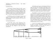
10.6 meters long, and has a range of 1,000<br />
miles (1,800 krn). A kit is available with which<br />
The <strong>Pershing</strong> II missile, with the normal the erector-launcher can be converted to<br />
configuration of first- and second-stage adapt to a single-stage missile, if required.<br />
propulsion sections and . the . reentry vehicle, The result is a missile with reduced weight,<br />
weighs more than 16,000 pounds, is about length, and range.<br />
I<br />
I<br />
1 1 FIRST-STAGE SECOND-STAGE REENTRY<br />
PROPULSION PROPULSION<br />
VEHICLE<br />
SECTION<br />
SECTION
FM 6-11 THE PERSHING II FIRING BAlTERY<br />
SWIVEL<br />
NOZZLE<br />
AIR VANES<br />
(2 FIXED, 2 MOVABLE)<br />
FIRST-STAGE<br />
PROPULSION SECTION<br />
The first stage provides the initial thrust<br />
required to propel the missile toward a<br />
ballistic trajectory. It consists of a rocket<br />
motor with attached forward and aft skirts.<br />
The forward skirt allows the second stage to<br />
be mated to the first stage. In a single-stage<br />
configuration, the reentry vehicle is mated<br />
directly to the forward skirt. The forward<br />
skirt contains three thrust termination ports.<br />
These ports stop the forward thrust at the<br />
time determined by the guidance and control<br />
section of the reentry vehicle when the<br />
missile is fired in the single-stage<br />
configuration. The first stage contains a<br />
motor ignition safe/arm mechanism<br />
designed to prevent the accidental launching<br />
of the missile. The aft skirt contains four air<br />
vanes (two fixed and two movable) and a<br />
swivel nozzle, which provide pitch and yaw<br />
control. The motor cases of both the first and<br />
second stages are made of Kevlar, a strong,<br />
-.<br />
lightweight material.<br />
FIRST-STAGE PROPULSION SECTION<br />
MOTOR IGNITION<br />
SAFE/ARM<br />
AFT<br />
SKIRT<br />
THRUST<br />
TERMlNATlO<br />
FORWARD<br />
SKIRT
SECOND-STAGE<br />
PROPULSION SECTION<br />
The second stage produces thrust for a<br />
variable amount of time and accelerates the<br />
missile to the required programed velocity for<br />
achieving target range. Like the first stage,<br />
the second stage consists of a solid-<br />
propellant rocket motor with attached<br />
forward and aft skirts. The forward skirt<br />
contains three thrust termination ports,<br />
which stop the forward thrust at the time<br />
determined by the guidance and control<br />
section of the reentry vehicle. The forward<br />
skirt also allows the stage to be mated to the<br />
reentry vehicle. The aft skirt houses a swivel<br />
nozzle with two hydraulic actuators for<br />
nozzle control. It provides a means for mating<br />
the first and second stages. The aft skirt also<br />
contains a linear shaped charge to cause<br />
first-stage separation.<br />
SWIVEL<br />
NOZZLE<br />
KEVLAR<br />
SYSTEM DESCRIPTION FM 6-1 1<br />
THRUST<br />
TERMINATION<br />
SOLID PORTS (3)<br />
AFT<br />
SKIRT
FM 6-1 1 THE PERSHING II FIRING BAITERY<br />
I<br />
REENTRY VEHICLE<br />
WARHEAD<br />
SECTION<br />
REENTRY VEHICLE<br />
The reentry vehicle (RV) consists of three<br />
sections: a guidance and control/adapter<br />
(G&C/A) section, a warhead section, and a<br />
radar section.<br />
GUIDANCE AND<br />
CONTROL/ADAPTER<br />
SECTION<br />
The guidance and control/adapter<br />
contains:<br />
The terminal guidance system.<br />
Thrusters to provide attitude control<br />
while in less dense atmosphere.<br />
Air vanes for roll control during<br />
second-stage thrust and full control once the<br />
reentry vehicle returns to denser atmosphere.<br />
I The adapter portion, which is designed<br />
so the reentry vehicle can be mated to either<br />
the first- or second-stage propulsion section.<br />
The adapter remains attached to the<br />
propulsion section when the reentry vehicle<br />
separates from it.
SYSTEM DESCRIPTION FM 6-1 1<br />
GUIDANCE AND CONTROL/ADAPTER SECTION<br />
t i<br />
The warhead section is a conical aluminum<br />
structure coated with an ablative material. It<br />
houses:<br />
A nuclear warhead that can provide an<br />
airburst, a surface burst, or an air/surface<br />
burst.<br />
H A permissive action link (PAL)<br />
unlocking device.<br />
II The rate gyro, which sends trajectory<br />
information to the G&C/A section.<br />
WARHEAD SECTION<br />
I 1
FM 6-1 1 THE PERSHING II FIRING BAlTERY<br />
I<br />
RADAR SECTION<br />
STABILIZED<br />
ANTENNA UNlT<br />
RADOME<br />
ASSEMBLY<br />
GROUND SUPPORT<br />
EQUIPMENT<br />
To be effectively employed, the <strong>Pershing</strong><br />
missile requires certain system-peculiar<br />
ground support equipment. This equipment is<br />
designed to provide speed, flexibility,<br />
reliability, and improved survivability.<br />
ERECTOR-LAUNCHER<br />
Each missile is fired from an erector-<br />
launcher (EL). The EL consists of a<br />
The radar section, consisting of a radome<br />
assembly, a radar unit, and a stabilized<br />
antenna unit, is located in the nose of the<br />
reentry vehicle. It transmits radio frequency<br />
(RF) energy to the target area, receives<br />
altitude and video return, and sends this<br />
altitude information to the on-board<br />
computer in the G&C/A section.<br />
RADAR UNlT<br />
transporter frame assembly that supports an<br />
erection system, a leveling system, a radar<br />
sectiodwarhead section assembly and<br />
transport pallet, a reentry vehicle cooling<br />
system, a ground integrated electronic unit<br />
(GIEU), a hydraulic control panel, and two<br />
28-volt DC power supplies. Through the<br />
GIEU, the EL operator can test and monitor<br />
EL functions and, when required, can control<br />
the countdown. The GIEU also provides<br />
launch site communications between the<br />
erector-launcher and the platoon control<br />
central.
PRIME MOVER<br />
ERECTOR-LAUNCHER<br />
PALLET n<br />
COVER \<br />
- REAR JACK<br />
ASSEMBLIES<br />
The ~trime mover for the erector-launcher is<br />
a 10-ton tractor with a self-recovery winch.<br />
Mounted on this tractor are the 30-kw<br />
generator, a power distribution box, a crane<br />
with a telescopic extension, and hydraulic<br />
stabilizer jacks.<br />
SYSTEM DESCRIPTION FM 6-1 1<br />
TRACTOR WITH CRANE AND 30-KW GENERATOR
FM 6-1 1 THE PERSHING ll FIRING BATTERY<br />
PLATOON CONTROL CENTRAL<br />
Each firing platoon has a platoon control<br />
central (PCC). It is mounted on a &ton,<br />
long-wheelbase, cargo truck. The power<br />
source for the PCC is the trailer-mounted<br />
30-kw generator. The PCC serves as the<br />
platoon command post, communications<br />
center, and launch control facility. Three<br />
remote launch control units (RLCU) are<br />
located in the PCC. They provide PAL<br />
functions, safe/arm functions, and firing<br />
control for up to three missiles on launchers.<br />
- Next -- to the RLCUs is an interface logic<br />
three keyboards for manual data entries,<br />
three alphanumeric displays for detailed<br />
countdown status information, and three line<br />
printers that provide hard copies of<br />
countdown data.<br />
The PCC also contains a launch window<br />
status display panel and a missile status<br />
display panel. The launch window status<br />
display panel computes time limits within<br />
which the platoon may launch its missiles.<br />
The missile status display panel gives the<br />
officer in charge (OIC) current missile<br />
countdown status information as it is<br />
assembly (ILA) console. The ILA contal%s developed by the ILA console.<br />
PLATOON CONTROL CENTRAL WITH TRAILER-MOUNTED<br />
30-KW GENERATOR<br />
ENTRY PANEL<br />
ANTENNA<br />
MAST BASES<br />
ENTRY PANEL<br />
PCC SHELTER<br />
CHEMICAL/ BIOLOGICAL<br />
PROTECTIVE<br />
GENERATOR
SYSTEM DESCRIPTION FM 6-1 1<br />
REFERENCE SCENE CABLES<br />
GENERATION FACILITY<br />
There are two reference scene generation<br />
facilities (RSGF) per Pershina 11 battalion.<br />
The RSGF consists of equipment to generate<br />
target cartridges. It uses a digital data base<br />
provided by the Defense Mapping Agency<br />
(DMA) to produce magnetic tape cartridges of<br />
digital target scenes for entry into the missile<br />
through the GIEU. The RSGF is mounted on<br />
a 5-ton, long-wheelbase truck. It contains a<br />
computer, mass storage units, video displays,<br />
and a tape cassette unit. The power source for<br />
the RSGF is a trailer-mounted 30-kw<br />
generator.<br />
Data and power are distributed within a<br />
platoon area through a ground support cable<br />
network.<br />
Two primary cables connected to the<br />
erector-launcher are required to launch the<br />
missile:<br />
A 50-foot cable provides power from the<br />
30-kw generator set to the erector-launcher<br />
through a power distribution box housed on<br />
the prime mover.<br />
A 400-foot cable conducts all electronic<br />
signals between the PCC and the<br />
erector-launcher.<br />
REFERENCE SCENE GENERATION FACILITY WITH TRAILER-<br />
MOUNTED 30-KW GENERATOR (AT BATTALION LEVEL)<br />
RSGF SHELTER
FM 6-1 1 THE PERSHING II FIRING BATTERY<br />
Additional cables include the following:<br />
B A 7-foot cable connecting the 30-kw<br />
generator set with the power distribution box.<br />
B A 150-foot AC power cable connecting a<br />
commercial or an alternate standby power<br />
source to the power distribution box. This<br />
cable connects power distribution boxes for<br />
distribution of standby power.<br />
B Three 50-foot ground cables with<br />
associated stakes, clamps, and rods.<br />
B Two short cables from the GIEU to the<br />
first stage, which provide power and<br />
electrical signals between the EL and the<br />
missile.<br />
ASSEMBLY<br />
FORWARD AREA<br />
CABLE SET<br />
REEL<br />
E R<br />
DISTRIBUTION<br />
CONTAINERS<br />
Containers are used to transport or store<br />
missile sections that are not assembled on an<br />
erector-launcher. All containers are top<br />
loading. The container covers are lifted by<br />
two top-mounted hoisting eyes. All missile<br />
section containers are designed so<br />
in-container tests can be performed through<br />
access ports without removal of the container<br />
covers.<br />
CONTAINERS<br />
ADAR<br />
ECTION<br />
SLING SETS<br />
The sling sets used in the PI1 firing battery<br />
consist of two- and four-leg slings,<br />
propulsion section hoisting beams, and a<br />
universal sling.<br />
The two-leg sling is used to remove and<br />
replace all missile section container covers,<br />
including the warhead section container<br />
cover. It is also used to handle either of the<br />
propulsion section hoist beams, with or<br />
without the propulsion section attached.
The four-leg sling is used to handle missile<br />
section containers (loaded or empty) and the<br />
PCC and RSGF shelters. Its construction is<br />
similar to that of the two-leg sling.<br />
The propulsion section hoisting beams are<br />
provided in two sizes. The larger hoisting<br />
beam is used to handle the first stage, and the<br />
smaller hoisting beam is used to handle the<br />
second stage. The hoisting beams are used<br />
to-<br />
Lift the propulsion sections to or from<br />
their containers.<br />
Position the sections on the launcher.<br />
Align the sections for assembly<br />
operations.<br />
The universal sling is used to lift either the<br />
G&C/A section, the warhead section, or the<br />
radar section. Three pairs of mounting holes<br />
are provided for lifting strap spacing to<br />
permit balanced lifting of the different<br />
sections.<br />
SECOND-STAGE<br />
SYSTEM DESCRIPTION FM 6-1 1<br />
TARGET REFERENCE<br />
SCENE PRODUCTION<br />
The reference scene generation facility is<br />
used to produce target cartridges. These<br />
cartridges, containing reference scenes and<br />
target data, are programed into the on-board<br />
computer of the missile. They are later<br />
compared with the live radar scan from the<br />
reentry vehicle. To produce target reference<br />
scenes, the RSGF must use information<br />
extracted from a target list and an<br />
operational data base.<br />
OPERATIONAL DATA BASE<br />
The operational data base (ODB) contains<br />
digitized elevation and topographic feature<br />
data stored on discs. These ODB discs are<br />
produced by the DMA and distributed to all<br />
<strong>Pershing</strong> I1 units.<br />
TARGET CARTRIDGES<br />
Target cartridges contain reference scenes<br />
and target data. Target data is programed<br />
into the missile by inserting the target<br />
cartridge into the GIEU on the erector-<br />
launcher. From the GIEU, the recorded target<br />
data is transferred to the on-board computer<br />
in the missile.<br />
TARGET CARTRIDGE<br />
MANAGEMENT<br />
The battalion targeting section, headed by<br />
the targeting officer, controls and distributes<br />
the cartridges as part of its tactical fire<br />
direction efforts. A target-to-cartridge<br />
assignment list received from the brigade<br />
headquarters specifies the arrangement of<br />
reference scenes for planned targets on each<br />
cartridge to be generated. Cartridges are<br />
labeled and become controlled documents.<br />
Reference local regulations for the<br />
identification, classification, security, and<br />
control of target cartridges.<br />
Field Storage. During field operations,<br />
the platoon control central is the storage<br />
location for all cartridges in the platoon's<br />
possession. The PCC safe has one drawer<br />
with a special rack that can hold a platoon's<br />
complement of target cartridges in a readily<br />
accessible configuration. Cartridges are<br />
removed from this safe only during<br />
countdown operations, cartridge exchange,<br />
or garrision storage.
FM 6-11 THE PERSHING II FIRING BATTERY<br />
Countdown Operations. When a<br />
cartridge is moved from the PCC to the firing<br />
site, it must be transported by a person with a<br />
clearance equal to or higher than the security<br />
classification of the cartridge.<br />
Cartridge Exchange. If cartridges must<br />
be exchanged for target change or<br />
maintenance reasons, classified material<br />
receipts will document the exchange.<br />
Defective cartridges found in firing unit<br />
countdown operations will be returned to the<br />
battalion targeting section for replacement.<br />
If the battalion targeting personnel can<br />
neither declassify the target data nor restore<br />
the cartridge to operational condition, the<br />
cartridge must be turned in for destruction as<br />
classified material. A replacement cartridge<br />
must be generated and fielded.<br />
COUNTDOWN OPERATIONS<br />
The <strong>Pershing</strong> I1 missile system can<br />
perform four types of countdowns: standard<br />
count, confidence count, quick count, and T-1<br />
count. Each count accomplishes specific<br />
functions within the missile, ensuring<br />
accomplishment of fire missions. TM<br />
9-1425-386-10-2 provides step-by-step<br />
procedures for performing countdowns.<br />
STANDARD COUNT<br />
The standard count provides the sequence<br />
of operations to launch a missile, beginning<br />
with the missile in the travel configuration on<br />
the erector-launcher. The purpose of the<br />
standard count is to perform all preflight<br />
checks and presets while preparing the<br />
missile for launch. Normally, the countdown<br />
terminates with missile lift-off.<br />
CONFIDENCE COUNT<br />
The confidence count is performed to verify<br />
equipment. It accomplishes the same<br />
sequence of preflight checks and presets as<br />
does the standard count. However, the<br />
confidence count ends when ALIGNMENT<br />
COMPLETE is indicated on the status<br />
display panel. At termination of the<br />
confidence count, the missile is placed in a<br />
standby or hot-hold condition. This allows<br />
the missile to undergo a quick count at a later<br />
time and be fired. A confidence count is<br />
performed periodically to verify system<br />
reliability. If needed, a confidence count may<br />
be switched to a standard count and the<br />
missile launched.<br />
QUICK COUNT<br />
The quick count is used for firing a missile<br />
after a confidence count has been performed.<br />
It begins with the missile in a standby<br />
condition and bypasses several of the<br />
preflight checks and presets associated with<br />
a standard count. The quick count may end<br />
with missile lift-off or, as with a confidence or<br />
standard count, any time before launch<br />
sequence initiation. The system may be put in<br />
either a standby or a hot-hold condition.<br />
T-1 COUNT<br />
The T-1 count is a training and evaluation<br />
vehicle. It allows an individual to see all the<br />
missile functions that occur during a<br />
standard or quick count, including missile<br />
erection, but without firing the missile. This<br />
count may be used in the training and<br />
evaluation of missile crews as well as in the<br />
evaluation of the missile system.<br />
TWO-STAGE<br />
FLIGHT SEQUENCE<br />
FIRST-STAGE IGNITION<br />
Milliseconds after ignition and lift-off, the<br />
missile begins to pitch, or tilt, toward the<br />
target at a predetermined rate. Initial thrust<br />
is provided by the first-stage rocket motor,<br />
which burns completely regardless of target<br />
range.<br />
COAST PERIOD<br />
After the first stage burns out, the missile<br />
enters a short coast period before the<br />
<strong>Pershing</strong> airborne computer (PAC) issues the<br />
separation signal.<br />
FIRST-STAGE SEPARATION,<br />
SECOND-STAGE IGNITION<br />
The first in-flight separation occurs<br />
between the first and second stages. A linear<br />
shaped charge in the second-stage aft skirt<br />
detonates, which causes the first stage to<br />
separate from the missile. The second stage<br />
then ignites, accelerating the remaining<br />
missile sections along the flight path.
SYSTEM DESCRIPTION FM 6-1 1<br />
SECOND-STAGE SEPARATION through the remaining trajectory to impact.<br />
Through the use of thruster assemblies, the<br />
on-board<br />
the<br />
computer indicate<br />
determined<br />
the missile<br />
by<br />
is<br />
the<br />
on<br />
the 'OrreCt path and has reached the<br />
necessary velocity and range, an in-flight<br />
separation occurs. Explosive devices in the<br />
adapter detonate. This causes an in-flight<br />
separation between the second-stage<br />
propulsion section and the reentry vehicle.<br />
Simultaneously, the thrust termination ports<br />
in the forward end of the second-stage rocket<br />
motor are activated to terminate the<br />
second-stage thrust.<br />
reentry vehicle maintains attitude control<br />
outside the atmosphere, Air vanes provide<br />
control once the reentry vehicle reenters the<br />
atmosphere, The radar in the nose of the<br />
reentry vehicle is activated during the final<br />
portion of flight and scans the terrain in the<br />
region of the target area. The computer<br />
converts the radar image to a digital<br />
representation of the target area,<br />
this "live scene,, to a previously stored<br />
reference, computes the adjustments<br />
necessary to hit the targe and applies those<br />
corrections using air vanes on the reentry<br />
REENTRY AND TERMINAL<br />
vehicle. This "search, compare, correct"<br />
GUIDANCE<br />
routine is repeated several times during the<br />
The reentry vehicle, with its on-board final phasesbf the trajectory. It provides the<br />
terminal guidance system, provides guidance same accuracy regardless of range.<br />
Q FIRST-STAGE<br />
TWO-STAGE FLIGHT SEQUENCE<br />
REENTRY VEHICLE<br />
ORIENTATION<br />
-. \<br />
/<br />
\<br />
\ia-----<br />
/<br />
\<br />
/ \<br />
/<br />
\<br />
/ \<br />
/<br />
\<br />
\ REENTRY<br />
\<br />
\<br />
4'<br />
THRUST TERMINATION 0' k \<br />
SECOND-STAGE<br />
/ SEPARATION B<br />
SEPARATION<br />
PITCH<br />
SEARCH,<br />
COMPARE,<br />
CORRECT
FM 6-11 THE PERSHING II FIRING BATTERY<br />
SINGLE-STAGE<br />
FLIGHT SEQUENCE<br />
The single-stage flight sequence is very<br />
similar to the two-stage flight sequence.<br />
FIRST-STAGE IGNITION<br />
First-stage ignition occurs as in the<br />
two-stage flight sequence. After lift-off, the<br />
missile maneuvers to a precomputed firing<br />
azimuth. The missile continues in flight<br />
under pitch and yaw control of a swivel<br />
nozzle and roll control of the first-stage air<br />
vanes. The first-stage motor burns until the<br />
proper velocity is achieved to allow free-fall<br />
onto the target.<br />
FIRST-STAGE SEPARATION<br />
There is no coast period in the single-stage<br />
flight sequence. Once the proper velocity is<br />
reached, the on-board computer issues a<br />
cutoff signal. At this time, the thrust reversal<br />
system (thrust termination ports) activates,<br />
the RV separation system activates, and the<br />
RV separates from the first stage at the<br />
adapter section.<br />
REENTRY AND<br />
TERMINAL GUIDANCE<br />
The reentry phases are identical for single-<br />
stage and two-stage flight sequences.
The mission of the field artillery roy, neutralize, or<br />
suppress the enemy by cannon, roc t, and missile fire and to he1<br />
integrate fire support into combin<br />
gives the theater commander the a<br />
at great range. Because of t<br />
capabilities of the system, Per<br />
periods to react quickly to fire<br />
<strong>Pershing</strong>-peculiar organizations<br />
chapter.<br />
To continue the deterrence role and<br />
enhance the system's survivability during<br />
periods of increased international tension or<br />
war, <strong>Pershing</strong> I1 units will deploy to field<br />
locations.<br />
The battalion commander gives each firing<br />
battery an area in which to position its<br />
elements. Normally, the battalion area will<br />
be quite large to accommodate t<br />
of the various elements.<br />
A firing battery occupies t<br />
platoon positions separated by at least 3 to 10<br />
km. Each light platoon position contains the<br />
firing platoon itself and enough communica-<br />
tions, operations, and maintenance support<br />
for semiautonomous operations. The platoon<br />
leader is the OIC of a light platoon position. A<br />
osition contains the third<br />
and the bulk of the<br />
ons, operations, maintenance,<br />
arters elements. The battery<br />
) is the OIC of the heavy<br />
n and, as in all command<br />
s responsible for mission<br />
ent by all elements of the<br />
ovement to initial field positions is<br />
directed by an emergency action message<br />
attalion operations center<br />
lion commander, through<br />
inates and directs the<br />
ts in accordance with<br />
battery will move to the<br />
in four serials. These<br />
ht firing platoons, the<br />
firing elment of the heavy platoon, and the<br />
headquarters/support element of the heavy<br />
atoon.
FM 6-11 THE PERSHING II FIRING BAlTERY<br />
FIRING BATTERY TASKS<br />
A firing battery may be given any one of<br />
the following four tasks to perform in the<br />
field:<br />
Assume quick reaction alert (QRA)<br />
target coverage immediately upon arriving at<br />
the position (immediate coverage). A missile<br />
is considered to be in QRA status when it has<br />
been prepared for a quick count and has been<br />
placed in standby.<br />
Prepare to assume target coverage at a<br />
later date (delayed coverage).<br />
Assume a hide configuration (maximize<br />
survivability) and await future taskings (no<br />
coverage).<br />
M Launch a single missile (single taraget).<br />
IMMEDIATE COVERAGE<br />
The firing position facilitates the task of<br />
immediately assuming QRA target coverage.<br />
The firing element completely emplaces the<br />
missiles and performs confidence counts in<br />
preparation for firing. All of the position's<br />
communications assets are operative, and<br />
the unit enters all appropriate communica-<br />
tions nets. While the primary task of a unit<br />
occupying a firing position is to be prepared<br />
to fire its missiles with minimum reaction<br />
time, the defense of the unit must not be<br />
forgotten. The QRA target coverage must be<br />
assumed as quickly as possible. Vehicles and<br />
equipment are positioned to minimize the<br />
possibility of detection from the air or from<br />
the ground. Communications must be<br />
minimized to avoid detection by radio<br />
direction finding.<br />
DELAYEDCOVERAGE<br />
The unit with the task of preparing to<br />
assume target coverage some time after<br />
deploying occupies a silent firing position.<br />
The silent firing position is configured<br />
basically the same as the firing position. The<br />
primary concern, however, is to avoid<br />
detection for as long as possible. Missiles are<br />
emplaced, but no countdowns are performed.<br />
Whenever possible, radio silence is observed.<br />
Normally, generators are not operated, and<br />
vehicle traffic should be kept to a minimum.<br />
Only when the unit is directed to assume<br />
target coverage will any countdowns be<br />
performed. Survivability is the key.<br />
NO COVERAGE<br />
The hide position is the primary<br />
survivability configuration for <strong>Pershing</strong> 11. A<br />
unit that is not expected to assume target<br />
coverage in the near future will be directed to<br />
occupy a hide position. As the name implies,<br />
the unit hides from the enemy. A tight vehicle<br />
configuration is most commonly used.<br />
Erector-launchers are not emplaced. Radio<br />
silence is observed unless the hide task is<br />
changed or cancelled. The unit may be tasked<br />
to fire single missiles from an external firing<br />
point. The equipment necessary to fire a<br />
single missile must be positioned to facilitate<br />
displacement and firing.<br />
SINGLE TARGET<br />
Single missiles may be fired from a unit's<br />
current position or, if time is available and<br />
the tactical situation permits, from an<br />
external firing point (EFP). An EFP should<br />
be located at least 5 km from the unit's<br />
principal position. It should provide adequate<br />
cover and concealment from enemy<br />
detection. The purpose of the EFP is to avoid<br />
compromising the main platoon position and<br />
to enhance survivability. Care should be<br />
taken to avoid compromising the location of<br />
the EF'P or the main platoon position during<br />
organization of, or movement to, the external<br />
firing point.<br />
ORGANIZATION<br />
The <strong>Pershing</strong> I1 firing battery is organized<br />
with a battery headquarters, an operations/<br />
communications platoon, three firing<br />
platoons, and a support platoon.<br />
The battery headquarters contains the<br />
personnel and equipment to provide:<br />
Command and control.<br />
Personnel services.<br />
Supply support.<br />
Nuclear surety administration.<br />
M Nuclear, biological, and chemical (NBC)<br />
defense and detection expertise.<br />
Food service support.<br />
The operations/communications platoon<br />
provides the personnel and equipment<br />
required to direct missile operations,<br />
maintain the battery crypto account, and
direct the employment of communications<br />
assets.<br />
The three firing platoons deploy, maintain,<br />
secure, and simultaneously fire three<br />
<strong>Pershing</strong> missiles. Personnel and equipment<br />
are provided to transport and assemble the<br />
missiles, input targeting data, operate the<br />
platoon control central (which controls<br />
missile launching), launch missiles,<br />
maintain missiles, secure nuclear weapons,<br />
and secure the position area. Administration,<br />
TASKS, ORGANIZATION, AND KEY PERSONNEL FM 6-1 1<br />
PERSHING FIRING BATTERY ORGANIZATION<br />
PERSHING<br />
FIRING<br />
supply, food service, communications, and<br />
maintenance support are provided by the<br />
battery.<br />
The support platoon manages all aspects of<br />
unit maintenance and directly supervises the<br />
distribution of petroleum, oils and lubricants<br />
(POL). The platoon has two sections-<br />
automotive maintenance and missile<br />
maintenance. During field operations,<br />
personnel from the maintenance sections are<br />
deployed with the firing platoons.<br />
FIRING/<br />
ASSEMBLY<br />
SECTIONS<br />
MISSILE<br />
MAINTENANCE<br />
SECTION<br />
SUPPORT<br />
PLATOON<br />
HEADCIUARTERS<br />
I<br />
I<br />
AUTOMOTIVE/ --<br />
ENGINEER<br />
MAINTENANCE<br />
SECTIONS
The battery commander (<br />
ultimately responsible for e<br />
battery does or fails to do. He ensures mission<br />
accomplishment. The battery commander<br />
must respond to calls for fire directly from the<br />
theater combined headq<br />
headquarters, and Army hea<br />
extraordinary rules and procedures. He is<br />
directly responsible for the movement,<br />
employment, and firing of his missiles, which<br />
are in three separate firing locations. Some of<br />
the battery commander's responsibilities<br />
follow:<br />
II Reconnoiter and select battery areas<br />
that afford mission accomplishment while<br />
providing for survivability.<br />
Plan specific actions to enhance the<br />
battery's survivability.<br />
II Plan unit marches and movements.<br />
II Supervise the security, preparation, and<br />
delivery of nuclear weapons.<br />
II Keep the battalion commander and<br />
battery personnel informed.<br />
II Establish and maintain communica-<br />
tions and electronics security.<br />
I1 Plan for battery supply and mainte-<br />
nance.<br />
II Manage the battery's personnel<br />
reliability program (PRP).<br />
II Ensure that all battery personnel are<br />
trained for combat.<br />
II Ensure that all battery equipment is<br />
maintained in accordance with applicable<br />
technical publications.<br />
The executive officer (KO) (CPT, 13C) is the<br />
battery commander's principal assistant and<br />
acts for the commander in his absence. He<br />
helps the commander command and control<br />
an organization spread over three locations.<br />
He coordinates and manages the battery's<br />
unit maintenance. He also supervises a shift<br />
in the battery control central (BCC) to<br />
facilitate 24-hour sustained operations. His<br />
duties include the following:<br />
II Ensure that timely and accurate fires are<br />
delivered by all firing platoons.<br />
II Ensure that before-, during-, and<br />
after-operation maintenance is performed in<br />
accordance with exact procedures stated in<br />
technical manuals.<br />
Is Ensure continual position area<br />
improvement.<br />
II Ensure that intrabattery communica-<br />
tions are maintained.<br />
Is Ensure that all safety procedures are<br />
followed.<br />
II Perform/supervise destruction<br />
procedures to prevent enemy use of battery<br />
equipment.<br />
I Supervise nuclear weapon release<br />
procedures.<br />
erform courier officer/convoy<br />
commander duties.<br />
OPERATIONS OFFICER<br />
The operations officer (CPT, 13C), assisted<br />
by the operations sergeant (E7, 15E),<br />
performs the same functions for the battery<br />
as the S2, S3, and communications-<br />
electronics staff officer (CESO) do for the<br />
battalion. As a key decision maker during<br />
normal firing operations, he establishes and<br />
maintains coverage of targets assigned to the<br />
battery. He is the platoon leader for the<br />
operations/communications platoon. His<br />
other responsibilities include the following:<br />
aintain status of nine missiles in three<br />
separate locations.<br />
i?# Assign targets and target data to include<br />
a real-time inventory of reference scenes.<br />
II Maintain control over PAL and<br />
emergency message authentication system<br />
(EMAS) material.<br />
II Coordinate battery ammunition<br />
resupply and special weapons security.<br />
II Coordinate security with supporting<br />
infantry personnel.<br />
erform/supervise destruction<br />
procedures to prevent enemy use of battery<br />
equipment.<br />
II Perforrn/supervise nuclear weapon<br />
release procedures.<br />
II Perform training officer functions.<br />
II Control all classified documents and<br />
communications security (COMSEC)<br />
materials.
II Provide for continuous BCC operations.<br />
II Ensure proper use of wire and radio nets.<br />
II Ensure that accurate records of missions<br />
are maintained.<br />
.I Perform courier officer/convoy<br />
commander duties.<br />
II Work shifts as BCC officer in charge.<br />
FIRING PLATOON LEADER<br />
The firing platoon leader (CPT, 13C)<br />
performs the same functions for the firing<br />
platoon, except administering the Uniform<br />
Code of Military Justice (UCMJ), as the BC<br />
does for the battery. In addition to being<br />
responsible for the platoon's performance,<br />
his responsibilities include the following:<br />
H Select suitable positions for the platoon<br />
to occupy.<br />
II Thoroughly train the advance party.<br />
II Perform courier officer/convoy<br />
commander duties.<br />
II Supervise special weapons operations.<br />
II Perform/supervise nuclear weapons<br />
release procedures.<br />
II Derive pace data to launch points for use<br />
in preparing manual data entries (MDE).<br />
Verify manual data entries.<br />
II Thoroughly train the missile crews.<br />
H Manage platoon equipment mainte-<br />
nance.<br />
II Employ and control platoon communi-<br />
cations assets.<br />
II Employ and control platoon security<br />
assets.<br />
II Work shift in the platoon control central.<br />
II Ensure continual position improvement.<br />
H Perform destruction to prevent enemy<br />
use of platoon equipment.<br />
FIRE CONTROL OFFICER<br />
The fire control officer (FCO) (LT, 13C) is<br />
the principal assistant to the firing platoon<br />
leader. While his main place of duty is in the<br />
PCC, the FCO must be prepared to act for the<br />
platoon leader in his absence. His duties<br />
include the following:<br />
II Work shift in the platoon control central.<br />
TASKS, ORGANIZATION, AND KEY PERSONNEL FM 6-1 1<br />
H Supervise PCC operations including<br />
PAL, safe/arm, countdown, and launch<br />
procedures.<br />
II Prepare manual data entries.<br />
II Compute launch data and verify target<br />
cartridges by <strong>Pershing</strong> identification (PID)<br />
number.<br />
II Secure and control classified documents<br />
within the platoon.<br />
II Perform/supervise nuclear weapons<br />
release procedures.<br />
H Develop and conduct the training<br />
program for PCC personnel.<br />
II Move the platoon to the next location on<br />
order.<br />
II Ensure continuous PCC operations.<br />
II Ensure proper use of wire and radio nets.<br />
H Ensure that accurate PCC records of<br />
missions are maintained.<br />
H Perform courier officer/convoy<br />
commander duties.<br />
H Perform destruction to prevent enemy<br />
use of platoon equipment.<br />
SUPPORT PLATOON LEADER<br />
The support platoon leader (LT, 13C),<br />
assisted by the senior maintenance<br />
supervisor (E7, 63B), supervises and trains<br />
the support platoon. His duties include the<br />
following:<br />
II Advise the BC on the formation of his<br />
maintenance program.<br />
Execute the BC's maintenance program.<br />
B Advise the BC and XO on the<br />
maintenance status of battery equipment,<br />
and provide information for readiness<br />
reports.<br />
E Manage the battery's prescribed load list<br />
(PLL) and POL resources.<br />
H Perform courier officer/convoy<br />
commander duties.<br />
MISSILE MAINTENANCE<br />
TECHNICIAN<br />
The missile maintenance technician (WO,<br />
214EO) is responsible for the supervision of<br />
all scheduled and corrective missile mainte-<br />
nance and liaison with the forward support<br />
company elements supporting his platoon.
FM 6-1 1 THE PERSHING II FIRING BATTERY<br />
His duties include the following:<br />
II Maintain platoon missile equipment,<br />
maintenance records, and status reports.<br />
II Coordinate maintenance beyond his<br />
capabilities with the support platoon leader<br />
and executive officer.<br />
II Help the platoon leader select a position.<br />
II Help the platoon leader during special<br />
weapons operations.<br />
II Give technical assistance/advice during<br />
missile operations (emplacement, counting,<br />
firing, march order, assembly).<br />
II Perform courier officer/convoy<br />
commander duties.<br />
II Perform destruction to prevent enemy<br />
use of platoon equipment.<br />
FIRST SERGEANT<br />
The first sergeant (1SG) (E8, 13Y) is the<br />
battery commander's principal enlisted<br />
assistant. His responsibilities include the<br />
following:<br />
II Ensure that enlisted supervisors are<br />
adequately trained.<br />
II Ensure that administrative and<br />
personnel actions within the battery are<br />
handled efficiently.<br />
Maintain status of all assigned enlisted<br />
personnel.<br />
Train enlisted members of the heavy<br />
position advance party.<br />
II Assemble the heavy position advance<br />
party.<br />
II Help reconnoiter and select battery<br />
areas.<br />
II Establish the track plan for occupation<br />
of the heavy position.<br />
Supervise occupation of and position<br />
support vehicles in the heavy position.<br />
Develop and brief the heavy position<br />
defense plan.<br />
II Designate and rehearse the heavy<br />
position reaction force.<br />
II Detail personnel to perform support<br />
functions in the heavy position (perimeter<br />
defense, sanitation, and kitchen police).<br />
II Coordinate administrative and<br />
logistical support.<br />
II Ensure that the light platoons have<br />
adequate defense plans, logistical support,<br />
and so forth.<br />
Perform duties as courier officer/convoy<br />
commander.<br />
FIRING PLATOON SERGEANT<br />
The firing platoon sergeant (E7,15E) is the<br />
firing platoon leader's principal enlisted<br />
assistant. Just as the platoon leader<br />
functions as the battery commander, the<br />
platoon sergeant functions as the first<br />
sergeant. His responsibilities include the<br />
following:<br />
II Ensure that all enlisted personnel of the<br />
platoon are adequately trained.<br />
Help reconnoiter and select platoon<br />
positions.<br />
II Supervise the security sweep of the<br />
platoon position.<br />
II Establish a track plan for occupation of<br />
the platoon position.<br />
II Supervise occupation of and position<br />
support vehicles.<br />
.I Develop and brief the platoon position<br />
defense plan.<br />
II Designate and rehearse the reaction<br />
force.<br />
II Detail personnel to perform support<br />
functions.<br />
.I Supervise the development of range<br />
cards for crew-served weapons.<br />
II Advise the chief of section.<br />
II Perform destruction to prevent enemy<br />
use of platoon equipment.<br />
Perform duties as courier officer/convoy<br />
commander.<br />
FIRING PLATOON CHIEF<br />
OF SECTION<br />
The firing platoon chief of section (E6,15E)<br />
is the platoon sergeant's principal assistant.<br />
He deals directly with missile operations. His<br />
duties include the following:<br />
II Ensure that all personnel in his section<br />
are properly trained.<br />
II Ensure readiness of his missiles.<br />
II Ensure that during countdown/firing,<br />
all crew duties are performed.
II Ensure that all prefiring checks are<br />
made.<br />
II Ensure that all section equipment is on<br />
hand and properly maintained.<br />
II Ensure that during missile assembly/<br />
disassembly, all crew duties are performed.<br />
II Prepare range cards for crew-served<br />
weapons.<br />
.I Supervise the preparation of fighting<br />
positions for both individual and<br />
crew-served weapons.<br />
TASKS, ORGANIZATION, AND KEY PERSONNEL FM 6-1 1<br />
II Be familiar with the position defense<br />
plan.<br />
II Implement his portion of the defense<br />
plan.<br />
II Perform duties as safety NCO.<br />
II Perform destruction to prevent enemy<br />
use of platoon equipment.<br />
I<br />
Perform duties as special weapons<br />
custodial agent.
CHAPTER 3<br />
RECONNAISSANCE,<br />
SELECTION, AND OCCUPATION<br />
OF POSITION<br />
On the battlefield, a sophisticated enemy can locate and engage a<br />
battery/platoon in various ways. To survive, it may have to move<br />
frequently. Frequent movement, however, reduces responsiveness<br />
and necessitates greater reliance on other units to assume the<br />
mission during displacement. To minimize movement time, all key<br />
personnel must be able to perform the reconnaissance, selection,<br />
organization, march, and occupation tasks quickly and efficiently.<br />
The keys to successful reconnaissance, selection, and occupation of<br />
position (RSOP) are discipline and team effort, which come from<br />
frequent and effective training.<br />
The headquarters controlling the movement of the battery directs<br />
the essential elements of the movement-when, where, and how. The<br />
battery commander/platoon leader must anticipate movement. He<br />
must plan in advance for displacement to new, alternate, or<br />
supplementary positions. The BC should advise the controlling<br />
headquarters of any factors to be considered in determining the who,<br />
when, where, and how of the movement. The BC must provide for<br />
coordination of survey support to platoons. He must consider the<br />
factors of mission, enemy, terrain, troops available, and time<br />
(METT-T) when selecting positions for his area of operations.
FM 6-1 1 THE PERSHING II FIRING BATERY<br />
MISSION:<br />
ENEMY:<br />
TERRAIN:<br />
TROOPS<br />
AVAILABLE:<br />
TIME:<br />
FACTORS OF METT-T<br />
Is the unit to operate in the<br />
hide, silent, or firing mode?<br />
What is the current threat?<br />
Can the unit communicate<br />
with higher and lower<br />
elements?<br />
Does the terrain support signal<br />
security?<br />
Does the terrain offer cover<br />
and concealment?<br />
Is the terrain defensible?<br />
Will the terrain support<br />
movement of the unit's<br />
equipment under all weather<br />
conditions?<br />
Does the unit have enough<br />
troops to defend the position<br />
and remain mission-capable?<br />
How much time does the unit<br />
have to accomplish the<br />
mission?<br />
SECTION I<br />
RECONNAISSANCE AND THE ADVANCE PARTY<br />
DEFINITION<br />
Reconnaissance is the examination of<br />
terrain to determine its suitability for<br />
accomplishment of the battery mission.<br />
RECEIPT OF ORDER<br />
The battery commander/platoon leader<br />
may receive displacement orders in varied<br />
formats, ranging from a five-paragraph<br />
operation order to a simple authenticated<br />
radio message. He is given, or selects himself,<br />
the general location of his new position, the<br />
time to depart and/or be in the new position,<br />
and the routes to be used.<br />
METHODS OF<br />
RECONNAISSANCE<br />
MAP RECONNAISSANCE<br />
Once the battery commander has been<br />
assigned his "goose egg," he identifies all<br />
potential positions within his allocated area<br />
and routes to those positions. He then assigns<br />
areas within which the platoon leaders<br />
perform detailed reconnaissance. A line of<br />
sight profile sketch may be included as part of<br />
the map reconnaissance to preclude problems<br />
with FM communications between positions.<br />
AIR RECONNAISSANCE<br />
Air reconnaissance is a useful supplement<br />
to the map reconnaissance. It decreases the
RECONNAISSANCE, SELECTION, AND OCCUPATION OF POSITION FM 6-1 1<br />
time required to assess a large battery<br />
position area. Care should be taken to avoid<br />
disclosure of position areas to enemy covert<br />
forces. When performing air reconnaissance,<br />
a commander should look for an area that<br />
provides a maximum number of launch and<br />
hide positions while avoiding open areas. He<br />
should concentrate on wooded or urban areas<br />
which are defensible and which permit<br />
maximum concealment of firing positions.<br />
GROUND RECONNAISSANCE<br />
A ground reconnaissance normally follows<br />
a map reconnaissance. This is the best<br />
method of determining the suitability of<br />
routes to be traveled and positions to be<br />
occupied. The actual conditions of routes and<br />
terrain patterns within the proposed area are<br />
seen. Before leaving his platoon, the platoon<br />
leader must give key information to his<br />
second in command, to include the following:<br />
ILocation of the new position area.<br />
I Possible routes.<br />
W Mission and enemy situation.<br />
I Any peculiar aspects of positions and/or<br />
routes if known.<br />
He goes to each of the positions identified<br />
through map or air reconnaissance. A survey<br />
team may go with him. While moving, he<br />
verifies the suitability of the routes. For<br />
example, he notes bridge and road<br />
classifications, location of obstacles, and<br />
likely ambush sites. After the reconnais-<br />
sance, he should return by an alternate route<br />
to verify its suitability for convoys if needed.<br />
Planning the ground reconnaissance must<br />
include measures to avoid detection and<br />
location of future positions by the enemy.<br />
-<br />
Note. Each method of reconnaissance offers the<br />
BC/platoon leader a different, but complementary,<br />
perspective. At times, aN three methods may be used.<br />
In most Instances, the BC/platoon leader performs a<br />
map reconnaissance, selects a tentative route, and<br />
then makes a ground reconnaissance.<br />
PLANNING THE<br />
RECONNAISSANCE<br />
In a fast-moving tactical situation, the<br />
time available for planning the reconnais-<br />
sance, assembling the advance party, and<br />
conducting the RSOP may be only a few<br />
minutes. Before departure, the commander<br />
must consider the primary and alternate<br />
routes and distances to the new position area.<br />
He must give the XO/FCO that information.<br />
The organization of the advance party<br />
must be tailored. The platoon leader/enlisted<br />
assistant takes only route guides and the<br />
personnel and equipment necessary to<br />
prepare the position for occupation. These<br />
personnel also provide their own defense and<br />
initial defense of the new position area.<br />
A standard nucleus of advance party<br />
personnel should be established. The<br />
equipment required to prepare a new position<br />
should be preloaded or identified and kept so<br />
that it can be located and loaded without<br />
delay.<br />
ASSEMBLING THE<br />
ADVANCE PARTY<br />
For either a deliberate or a hasty<br />
occupation, a prearranged signal or<br />
procedures should be used to alert and<br />
assemble the advance party. The signal<br />
should be specified in the unit SOP, which<br />
should also list the advance party personnel,<br />
equipment, vehicles, and place of assembly.<br />
ORGANIZATION OF THE<br />
ADVANCE PARTY<br />
The makeup of the party is determined by<br />
the platoon leader and platoon sergeant. It is<br />
based on the tactical situation and assets<br />
available.<br />
The advance party is preceded to the<br />
position area by the supporting infantry<br />
contingent. The infantry reconnoiters the<br />
selected route to ensure it is free of Threat<br />
forces. To avoid compromising actual<br />
positions, the infantry does not enter the<br />
position. Rather, it performs a security sweep<br />
around the position, sets up listening posts<br />
(LP)/observation posts (OP), and begins<br />
patrolling. Communications must be<br />
maintained between the infantry, the<br />
advance party, and the main body.<br />
The size of the advance party must be kept<br />
to a minimum to avoid detection. Normally,<br />
platoon leaders lead the advance parties that
FM 6-1 1 THE PERSHING II FIRING BAlTERY<br />
organize the new platoon positions. During<br />
the organization phase, adequate security<br />
should be maintained to protect against a<br />
small, squad-size force. Positive measures<br />
must be taken to conceal the location of the<br />
unit and to avoid detection.<br />
If NBC warfare has been initiated, an NBC<br />
survey monitoring team should go with the<br />
advance party to check for NBC contamina-<br />
tion. Upon arrival at the position, the<br />
advance party should be in the NBC<br />
protective posture dictated by the situation.<br />
First, the survey monitor team takes<br />
environmental samples of the entrance to the<br />
1. SITUATION<br />
a. Enemy Situation. Rear area activity, major<br />
avenues of approach, air activity, and potential<br />
ambush sites.<br />
b. Friendly Situation. Changes in tactical<br />
mission and location of adjacent units.<br />
2. MISSION<br />
Changes in mission of the platoon, if any (for<br />
example, targeting, assignments and coverage,<br />
and generation levels).<br />
3. EXECUTION<br />
a. Concept of Operation. General location of<br />
platoon positions, routes, and order of march.<br />
area. The results of the sampling are brought<br />
to the officer in charge. He determines<br />
whether the position is tenable and if any<br />
change to the NBC mission-oriented<br />
protective posture (MOPP) is necessary. If the<br />
position is tenable, the security team sweeps<br />
the area and establishes a defensive<br />
perimeter.<br />
MAKING THE<br />
RECONNAISSANCE<br />
Before departing, the platoon leader must<br />
brief key personnel and advance party<br />
members.<br />
b. Coordinating Instructions. Location of start<br />
point, release point, and start point time if<br />
known/used.<br />
c. Mission-Oriented Protective Posture Status.<br />
4. ADMINISTRATION AND LOGISTICS<br />
??/hen and where to feed personnel, and priority<br />
for maintenance and recovery.<br />
5. COMMAND AND SIGNAL<br />
a. Command. Changes in location of<br />
battalion/battery command post.<br />
b. Signal. Movement radio frequency and net<br />
control restrictions.
RECONNAISSANCE, SELECTION, AND OCCUPATION OF POSITION FM 6-1 1<br />
After being briefed by the platoon leader,<br />
the fire control officer/platoon sergeant<br />
should brief his remaining key personnel on<br />
the following:<br />
II Tactical situation.<br />
II Routes to be used.<br />
II Any anticipated problems.<br />
Movement time, if known.<br />
After making a map reconnaissance,<br />
completing his planning, and briefing<br />
necessary personnel, the platoon leader is<br />
ready to proceed to the new location. The<br />
primary purpose of the route reconnaissance<br />
is to verify the suitability of the primary<br />
route. The platoon leader also checks:<br />
II Alternate routes (time permitting).<br />
II Road conditions and bridge classifica-<br />
tions.<br />
I Cover and concealment.<br />
II Location of obstacles.<br />
II Likely ambush sites.<br />
II Time required.<br />
II Distance.<br />
Likely position areas along the route.<br />
BASIC TYPES OF POSITIONS<br />
The platoon leader must select three basic<br />
types of positions-primary, alternate, and<br />
supplementary. Positions are further<br />
identified as heavy or light, depending on the<br />
units occupying them.<br />
PRIMARY POSITION<br />
The primary position is one from which a<br />
platoon intends to accomplish its assigned<br />
mission.<br />
ALTERNATE POSITION<br />
The alternate position is the one to which<br />
the entire platoon moves if its primary<br />
SECTION II<br />
SELECTION OF POSITION<br />
position becomes untenable. Since the<br />
platoon will continue its mission from the<br />
alternate position, it must meet the same<br />
requirements as the primary position and<br />
should be far enough away that the unit can<br />
escape the effects of enemy indirect fire on the<br />
primary position. It should be reconnoitered<br />
and prepared for occupation as time permits.<br />
Each section chief must know the route to the<br />
alternate position, because movement to that<br />
position &ay be by section.<br />
SUPPLEMENTARY POSITION<br />
A supplementary position, such as an<br />
external firing point, is selected for<br />
accomplishment of a specific mission.<br />
3-5
FM 6-1 1 THE PERSHING II FIRING BAlTERY<br />
HEAVY AND LIGHT POSITIONS<br />
The battery headquarters is collocated with<br />
a firing platoon in the heavy platoon<br />
position. The battery headquarters should be<br />
located to provide the best communications<br />
with the subordinate firing platoons and<br />
battalion headquarters. Each of the other two<br />
firing platoons is located in a light platoon<br />
position. A consideration in light platoon<br />
area selection is that fewer resources are<br />
available for defense. To enhance<br />
survivability, from 3 to 10 km between firing<br />
platoon positions is desired. Exact distance<br />
depends on the expected threat.<br />
LOCATION OF PLATOON POSITIONS
RECONNAISSANCE, SELECTION, AND OCCUPATION OF POSITION FM 6-1 1<br />
SPECIFIC TYPES OF<br />
POSITIONS<br />
In addition to the three types of positions<br />
mentioned before, the platoon leader must<br />
select positions that support the tasks<br />
assigned. These are the firing, silent firing,<br />
and hide positions; an external firing point;<br />
and, if required, an assembly area.<br />
FIRING POSITION<br />
Accomplishing the mission of firing<br />
missiles must take precedence in selection of<br />
a firing position. While overhead cover is<br />
essential for survival, it must not interfere<br />
with a missile during lift-off. Therefore, at<br />
least a 10-foot hole must be in the overhead<br />
cover of each launch point. The position must<br />
be large enough that ancillary equipment can<br />
be placed out of the blast zones, yet small<br />
enough to defend. An established road<br />
network that can support the weight of an<br />
erector-launcher with missile and that<br />
affords separate entry and exit routes should<br />
be used when possible. Missiles must be<br />
positioned within the constraints specified by<br />
the appropriate technical manuals. Ancillary<br />
vehicles are normally positioned to protect<br />
the missiles from direct fire and ground<br />
observation from outside the position.<br />
SILENT FIRING POSITION<br />
The silent firing position increases<br />
survivability while affording a minimum<br />
response time for a fire mission. The RSOP<br />
considerations are the same as for a firing<br />
position. The equipment is emplaced for<br />
firing; however, no power is generated.<br />
Passive defense measures are strictly<br />
enforced, as for the hide position.<br />
HIDE POSITION<br />
When a platoon is not required to assume<br />
target coverage, survival is its primary task.<br />
All measures of passive defense must be<br />
strictly followed, as prescribed in chapter 4.<br />
The RSOP considerations for successful hide<br />
operations are as follows:<br />
W Missile equipment is not positioned for<br />
firing.<br />
Equipment is positioned to reduce<br />
defense requirements.<br />
An exclusion area is established for any<br />
nuclear weapons present.<br />
W A restricted area for the BCC/PCC,<br />
single sideband (SSB) radios, and tactical<br />
satellite (TACSAT) must be planned.<br />
W The hide position should be near selected<br />
firing positions. That would minimize the<br />
time required to move and begin firing<br />
operations.<br />
II Positioning should be planned so missile<br />
equipment can be easily moved out of the<br />
position without the entire platoon having to<br />
move.<br />
II There should be enough room between<br />
vehicles that if one vehicle becomes<br />
inoperable, others can get around it.<br />
II Equipment must be concealed from the<br />
sides as well as from overhead with enough<br />
cover to prevent detection by observers and<br />
side-looking airborne radar.<br />
The best hide position allows expansion to<br />
a silent firing position or a firing position<br />
without moving the platoon to a different<br />
area.<br />
EXTERNAL FIRING POINT<br />
An external firing point is a position to<br />
which one missile is taken and prepared for<br />
launch. Covert operations are absolutely<br />
essential. The only equipment taken is that<br />
necessary to launch the missile (including<br />
communications and operations equipment),<br />
provide security, and communicate. An<br />
advance party is not needed in most cases.<br />
Because of the minimal equipment, the<br />
position is much smaller than that of a firing<br />
platoon. Noise and light discipline is an<br />
absolute must during all aspects of EFP<br />
operations.<br />
ASSEMBLY AREA<br />
After initial rounds are fired, battery assets<br />
may have to be consolidated for continued<br />
operations. The assembly area is designed to<br />
facilitate missile and warhead resupply as<br />
well as missile assembly operations before<br />
the platoons or sections of platoons occupy<br />
other firing positions.<br />
Many of the criteria for the selection and<br />
occupation of firing positions apply to<br />
assembly areas. The major exception is that<br />
the mission to be performed normally does<br />
not include firing missiles. A long, wide, level,
FM 6-1 1 THE PERSHING II FlRlNG BATTERY<br />
easily trafficable area must be selected to The size of the assembly area depends on<br />
easeresupply andmissileassembly theamountofequipmentitwil1contain.Fora<br />
operations and to hold the remaining assets complete firing battery, the position must be<br />
of the entire battery. The area also must extremely large. Extra fighting positions on<br />
provide necessary concealment. the defensive perimeter may be necessary.<br />
COMPARISON OF POSITIONS<br />
I I I I 1 I I<br />
Missiles<br />
emplaced<br />
Confidence<br />
counts<br />
Standard counts<br />
Communications<br />
assets . Messing<br />
Overhead cover<br />
Generators<br />
Camouflage<br />
SILENT<br />
FIRING FIRING<br />
POSITION POSITION POSITION<br />
N o No Yes<br />
No N 0 No<br />
FM only FM only All<br />
Cold Cold Hot<br />
man-made man-made man-made<br />
TASKS IN ORGANIZA TlON<br />
<strong>Organization</strong> of the platoon position<br />
includes:<br />
Designating locations of vehicles,<br />
facilities, and equipment.<br />
Briefing vehicle guides.<br />
III Preparing the track plan.<br />
Designating vehicle order of march for<br />
the main body.<br />
Designating chemical agent sampling<br />
locations.<br />
Preparing the defense plan.<br />
I Preparing a plan for internal wire<br />
communications. When time permits, wire<br />
should be laid before the main body arrives.<br />
SECTION 111<br />
ORGANIZATION OF POSITION<br />
EXTERNAL<br />
FIRING<br />
POINT<br />
Yes<br />
N 0<br />
Yes<br />
All<br />
Cold<br />
Holes<br />
All<br />
Natural<br />
ASSEMBLY<br />
AREA I<br />
man-made<br />
LAUNCH POINT<br />
IDENTIFICATION<br />
A firing position must allow for safe and<br />
unobstructed launch of all missiles.<br />
Availability of an adequate launch area<br />
drives the selection of the position. (A launch<br />
area in a firing position normally contains<br />
three missiles on erector-launchers.) The<br />
major considerations in launch area selection<br />
include the following:<br />
.I Launch paths-Overhead cover must<br />
not obstruct missile firing.<br />
.I Blast zones-The area must be large<br />
enough to allow equipment emplacement<br />
away from the missile blast. See TM<br />
9-1425-386-10-2/1. Blast effects, not only on<br />
personnel but also on low-lying vegetation,<br />
should be considered.
RECONNAISSANCE, SELECTION, AND OCCUPATION OF POSITION FM 6-1 1<br />
.I Terrain slope tolerance-A slope of 6" or<br />
less is required for erector-launchers.<br />
Erector-launchers-The erector-<br />
launchers must be concealed from air and<br />
ground observation. Missiles should be<br />
protected from direct engagement by<br />
small-arms fire from outside the perimeter.<br />
II Emplacement positions for erector-<br />
launchers must be able to support the weight<br />
of the vehicle and allow erection of the<br />
missile.<br />
II Distance between launch points cannot<br />
exceed interconnecting cable lengths.<br />
FACILITIES<br />
AND EQUIPMENT<br />
The current situation dictates the need for<br />
tactical dispersion of equipment, for natural<br />
cover and concealment, and for other passive<br />
defense measures in position selection.<br />
Capabilities and limitations of communica-<br />
tions equipment must be considered in siting<br />
the platoon headquarters. The BCC/PCC<br />
and defense control center (DCC) positions<br />
must be selected to facilitate radio<br />
communications as well as landline<br />
communications to the defensive perimeter<br />
and the launch area. The position must<br />
facilitate missile section and RV loading and<br />
mating operations. There should be room to<br />
position vehicles delivering sections and RVs<br />
as well as to reposition the materiel-handling<br />
crane mounted on the prime mover. The<br />
position should facilitate generator refueling<br />
as required.<br />
The position must facilitate both active and<br />
passive defense measures. A defensible<br />
position should-<br />
II Deny enemy observation during<br />
occupation.<br />
.I Provide natural concealment.<br />
.I Provide multiple entry and exit routes.<br />
.I Permit the unit to mask communications<br />
emitters behind hill masses.<br />
Provide adequate fields of fire and<br />
visibility to properly defend the position.<br />
8 Permit emplacement of all equipment in<br />
a small area so that a minimum number of<br />
fighting positions can adequately support a<br />
defensive perimeter.<br />
TRACK PLAN AND<br />
VEHICLE ORDER OF MARCH<br />
The area must be such that vehicles can get<br />
in and out of it. A <strong>Pershing</strong> I1 platoon has<br />
many large, wide, and heavy vehicles. Tree<br />
density, softness of ground, and slope of<br />
terrain must be considered. Missiles on<br />
erector-launchers will probably have to stay<br />
on hard-surface or semihard-surface roads<br />
because of their extreme weight. There should<br />
be sufficient drainage in the area that a<br />
platoon will not get bogged down during a<br />
heavy rain. The track plan should clearly<br />
show how vehicles will move into and out of<br />
the position. It should also identify the main<br />
body order of march, the convoy release<br />
point, and the vehicle guide pickup point. The<br />
vehicle order of march should be given to the<br />
main body before movement, and it should<br />
facilitate occupation.<br />
DEFENSE PLAN<br />
The defense plan should be a sketch of the<br />
defensive perimeter, observation/listening<br />
posts, patrol areas, minefields, and early<br />
warning measures. It must provide for 360'<br />
defense of the perimeter as well as defense in<br />
depth. Missiles must be protected from<br />
small-arms fire from outside the perimeter.<br />
Auxiliary vehicles may be used for protection<br />
of missiles and then be moved out of blast<br />
zones before launch. Chapter 4 presents<br />
detailed defensive considerations.<br />
INTERNAL WIRE PLAN<br />
The wire plan should identify each TA-312<br />
telephone and termination point within each<br />
heavy and light platoon area. The perimeter<br />
positions will have wire communications<br />
with the DCC switchboard. Wire communi-<br />
cations will be maintained between the DCC<br />
and the BCC/PCC, the mess facility,<br />
observation and listening posts (OPs/LPs<br />
will have to rely on FM communications<br />
during initial emplacement), and the<br />
exclusion area gate (X-gate). The BCC/DCC<br />
must keep direct wire communications with<br />
all radio facilities. If the reaction forces are<br />
not at the DCC, communications must be<br />
maintained from the DCC to these forces.
FM 6-1 1 THE PERSHING II FIRING BA7TERY<br />
VEHICLE GUIDES<br />
Guides must know where each vehicle and<br />
facility will be located as specified by the<br />
track plan. They must also know in which<br />
direction to point the vehicle to facilitate its<br />
departure. Guides must walk the route from<br />
the pickup point to the vehicle/facility<br />
location and ensure that the route is<br />
MOVEMENT METHODS<br />
Normally, the firing battery moves by<br />
platoon. The movement order for the main<br />
body includes start point (SP) and release<br />
point (RP) times as well as the order of march.<br />
A vehicle from the advance party meets the<br />
main body at the release point and leads the<br />
convoy to the pickup point. Vehicle guides<br />
control vehicle movement from the pickup<br />
point to the individual vehicle locations.<br />
(Vehicles carrying warheads require point<br />
guards at this time.) The position should be<br />
quickly occupied as specified in the track<br />
plan. Units must be drilled extensively on all<br />
movement methods to minimize the time they<br />
are unable to provide fire support. The<br />
loading of equipment on vehicles and trailers<br />
begins upon receipt of a warning order to<br />
move. Consistent with the mission,<br />
communications equipment is switched from<br />
the static to the mobile mode of operation.<br />
Missiles and related equipment should be<br />
prepared for transport as soon as possible.<br />
There are two primary methods of moving<br />
a <strong>Pershing</strong> unit in a tactical configuration-<br />
open column and closed column. Each<br />
method has it specific advantages and<br />
disadvantages. The battery commander/<br />
platoon leader decides which method is best.<br />
OPEN COLUMN<br />
The open column is used for daylight<br />
movements whenever there is an adequate<br />
road network that is not overcrowded, when<br />
enemy detection is not likely, when time is an<br />
SECTION IV<br />
TACTICAL MARCHES<br />
unobstructed. When moving vehicles into the<br />
position area, guides begin controlling<br />
vehicle movement at the pickup point.<br />
Vehicles must be moved off the road as soon<br />
as possible to avoid detection. If there are not<br />
enough guides for each vehicle, guides should<br />
be located for maximum control and to help<br />
assistant drivers quickly position vehicles<br />
and equipment.<br />
important factor, and when there is<br />
considerable travel distance involved. The<br />
vehicle interval in an open column is<br />
generally 100 meters.<br />
Advantages of this method are:<br />
Speed (the fastest method of march).<br />
.I Reduced driver fatigue.<br />
Improved vision on dusty roads.<br />
II Ease in passing individual vehicles.<br />
II Ease in dispersing vehicles as a passive<br />
defense measure against an air attack.<br />
II Less chance of the entire unit being<br />
ambushed.<br />
Disadvantages of this method are:<br />
.I Greater column length requires more<br />
road space.<br />
Other traffic often becomes interspersed<br />
in the column.<br />
Communication within the column is<br />
complicated.<br />
CLOSED COLUMN<br />
For closed column movement, the vehicle<br />
interval is less than 100 meters. At night,<br />
each driver can watch the cat's-eyes of the<br />
blackout markers on the vehicle in front of<br />
him and keep an interval of 20 to 50 meters. If<br />
the driver sees two marker lights, the interval<br />
is too great. If he sees eight marker lights, he<br />
is too close. If he sees four marker lights, he is<br />
maintaining the proper interval. During<br />
daylight, closed column is used when there is<br />
a need for maximum command and control;
RECONNAISSANCE, SELECTION, AND OCCUPATION OF POSITION FM 6-1 1<br />
for example, during periods of limited<br />
visibility or when moving through built-up or<br />
congested areas.<br />
Advantages of this method are:<br />
8 Simplicity of command and control.<br />
II Reduced column length.<br />
Concentration of defensive firepower.<br />
Disadvantages of this method are:<br />
8 Column is vulnerable to enemy<br />
observation and attack.<br />
Strength and nature of the column are<br />
quickly apparent to enemy observers.<br />
Convoy speed is reduced.<br />
8 Driver fatigue increases.<br />
CAT'S-EYES BLACKOUT<br />
MARKERS<br />
@ 'OirZF @<br />
50 METERS<br />
::z::<br />
JUST RIGHT<br />
@ @<br />
TOO CLOSE<br />
LESS<br />
THAN<br />
@ 20 @<br />
LOADING PLAN/LIST<br />
A loading plan/list is particularly<br />
important in sustained combat, and each<br />
vehicle should have one. The loading plan<br />
should be recorded and graphically<br />
illustrated. The loading list need not be<br />
graphically illustrated. The plan/list helps<br />
ensure the unit will close on the new position<br />
with all its equipment. Personnel responsible<br />
for preparing loading plans/lists should<br />
consider the mission, personnel, SOP, and<br />
equipment of the battery. Equipment needed<br />
first during occupation should be loaded last.<br />
Steps in preparing the loading plan/list<br />
include:<br />
Examine the modified tables of<br />
organization and equipment (MTOE) to<br />
determine the personnel, equipment, and<br />
vehicles authorized for each section.<br />
Examine all tables of distribution and<br />
allowances (TDA) property that must be<br />
transported by the battery. This equipment<br />
should be carried by the section that uses it.<br />
r List the personnel and equipment to be<br />
carried in each vehicle. Equipment should be<br />
loaded the same way for each move to aid in<br />
identification under blackout conditions.<br />
Technical manual guidance, if available,<br />
should be followed.<br />
Practice loading, and adjust the plan if<br />
necessary.<br />
8 Establish a list of items that must be<br />
removed from the vehicle and carried forward<br />
if the vehicle becomes disabled during<br />
movement.<br />
Consistent with mission requirements,<br />
vehicles should remain uploaded.<br />
FINAL PREPARATIONS<br />
Preparation for the move should include:<br />
8 Preoperative maintenance checks by<br />
vehicle drivers.<br />
Reloading of all off-loaded equipment.<br />
Complete loading of all service elements;<br />
for example, mess, supply, and maintenance.<br />
II A briefing by the convoy commander to<br />
the drivers. It should cover such subjects as '<br />
safety and instructions addressed in the<br />
march order, the tactical situation, and the<br />
mission. Strip maps may be issued at this<br />
time.<br />
The organization of the march column<br />
varies according to the tactical situation and<br />
the position area to be occupied. The<br />
following points should be considered:<br />
r The launchers should be dispersed<br />
throughout the entire column with at least<br />
one buffer vehicle between missiles.<br />
Vehicles should be arranged in an order<br />
t,hat allows speedy, organized occupation of<br />
the new position and defense during<br />
movement and occupation.
FM 6-11 THE PERSHING II FIRING BATTERY<br />
Each vehicle should have an assistant<br />
driver, who also serves as an air guard.<br />
Machine guns should be distributed<br />
evenly throughout the column and aimed<br />
alternately to the left and right sides of the<br />
route of march.<br />
Canvas should be removed so personnel<br />
can have their individual weapons poised to<br />
return fire if necessary. Unit SOP should<br />
specify if some personnel are to fire with their<br />
weapons on full AUTO and some with them<br />
on SEMIAUTO.<br />
Key personnel should be dispersed<br />
throughout the column.<br />
Fire-fighting equipment should be<br />
positioned behind the last launcher in the<br />
convoy (except fire extinguishers, which<br />
should be with each vehicle/trailer).<br />
A means to destroy equipment to prevent<br />
enemy use must be readily available.<br />
CONVOY CONTROL<br />
MEASURES<br />
The start point is normally a geographical<br />
feature identifiable on the ground and on a<br />
map. The first vehicle of a convoy should<br />
cross the start point at the specified time.<br />
A checkpoint (CP) is normally a<br />
geographical feature identifiable on the<br />
ground and on a map. It is used in reporting<br />
progress along the route of march.<br />
The release point is normally a<br />
geographical feature identifiable on the<br />
ground and on a map. The last vehicle of a<br />
convoy should cross the release point at a<br />
specified time. Guides from the advance<br />
party meet the convoy at the release point to<br />
lead the vehicles into the new position area.<br />
Radio transmissions should be avoided<br />
during marches to deny the Threat signal<br />
intelligence. Battery SOPS should give<br />
procedures for the use of radios, messengers,<br />
flags, whistle and horn signals, pyrotechnic<br />
signals, and hand and arm signals. (Usage<br />
should be in accordance with NATO<br />
Standardization Agreement [STANAG]<br />
2154/Quadripartite Standardization<br />
Agreement [QSTAG] 539 [as shown in<br />
appendix A].) Radio transmissions should be<br />
as brief as possible. At no time should specific<br />
information that could compromise the<br />
convoy's location be broadcast over the radio;<br />
for example, EXITING THE HIGHWA Y or<br />
PASSING THROUGH TOWN. References<br />
to location should be limited to, for example,2<br />
KILOMETERS SOUTHWEST OF<br />
CHECKPOINT NOVEMBER KILO,<br />
HAVE ARRIVED AT RELEASE<br />
POINT.<br />
MARKING THE ROUTE<br />
Road guards may be posted at critical<br />
locations where elements of the march might<br />
make a wrong turn. However, priority must<br />
be given to avoiding detection. Provisions<br />
should be made for prompt pickup of the road<br />
guards when they are no longer needed. If<br />
personnel are not available, route markers<br />
can be used. (Be careful not to compromise the<br />
unit's location or identity.) Details<br />
concerning traffic control and route<br />
markings are in FM 19-25 and FM 55-30.<br />
CONDUCT OF THE MARCH<br />
The main body of the heavy or light platoon<br />
should move at night, if possible, to avoid<br />
location by the enemy. Nuclear convoys must<br />
be conducted in accordance with procedures<br />
described in chapter 5, in FM 100-50, and by<br />
local policies. During movement, the enemy<br />
must be prevented from following the convoy<br />
to the new position. Speed of the convoy and<br />
control of civilian vehicles are necessary to<br />
avoid detection. Saboteurs and small,<br />
unconventional forces must be prevented<br />
from effectively engaging units with<br />
small-arms fire.<br />
MARCH DISCIPLINE<br />
Convoys may be organized into serials,<br />
which are groupings of march units under<br />
separate convoy commanders. The size of the<br />
serial should be consistent with the mission<br />
and the tactical situation. For example, a<br />
serial may consist of one platoon's vehicles,<br />
personnel, and equipment; or it may consist<br />
of one firing crew's vehicles, personnel, and<br />
equipment. The support personnel and<br />
equipment of the battery HQ area may deploy<br />
as a separate "admin" serial.<br />
Officers and NCOs should ride where they<br />
can best control and supervise the march of<br />
their units. One of these individuals rides at<br />
the head of each serial. The senior person in
RECONNAISSANCE, SELECTION, AND OCCUPATION OF POSITION FM 6-1 1<br />
each vehicle is responsible for ensuring that<br />
all orders concerning the march are carried<br />
out. All vehicles maintain their order of<br />
march unless directed or until circumstances<br />
dictate otherwise.<br />
The column should keep moving. The unit<br />
SOP should prescribe recovery procedures for<br />
disabled vehicles. It should also indicate who<br />
stops to pick up mission-essential personnel.<br />
Normally, halts are not scheduled for<br />
tactical marches. If a halt is necessary, a<br />
wooded area should be selected as the halting<br />
place. Vehicles should be dispersed off the<br />
road and concealed.<br />
The assistant driver watches for signs,<br />
markers, signals, and other traffic. He must<br />
also ensure the driver is alert and safely<br />
operating the vehicle at all times.<br />
March discipline is attained through<br />
training and internal control. The specific<br />
objective of march discipline is to ensure<br />
cooperation and effective teamwork by<br />
march personnel. Teamwork includes:<br />
Immediate and effective response to all<br />
signals.<br />
II Prompt relaying of all signals.<br />
II Obedience to traffic regulations and to<br />
the instructions of traffic control personnel.<br />
II Use of concealment, camouflage,<br />
dispersion, radio listening silence, blackout<br />
precautions, smoke, and other protective<br />
measures against air, ground, and NBC<br />
attack.<br />
II Maintenance of safe speeds, positioning,<br />
and intervals between vehicles within the<br />
column.<br />
II Recognizing route marking signals/<br />
signs.<br />
II Use of correct procedures for handling<br />
disabled vehicles.<br />
Radio contact, preferably secure, between<br />
lead and trail vehicles should be provided for<br />
convoy control.<br />
CONTINGENCIES<br />
IMMEDIATE ACTION PROCEDURES<br />
Because of its nuclear capabilities,<br />
<strong>Pershing</strong> I1 is always a high-priority target<br />
for the Threat. A battery can greatly decrease<br />
its vulnerability to attack by establishing an<br />
SOP for immediate actions. The following<br />
should be considered:<br />
II Enemy situation-the type of attack that<br />
can be expected.<br />
II Organic resources for countering the<br />
different types of attack.<br />
II Nonorganic support available for<br />
countering attacks.<br />
II Type of communications to be used with<br />
the immediate actions, such as flags, radio,<br />
and arm and hand signals.<br />
II How best to protect the unit.<br />
II How best to neutralize the attack.<br />
AIR ATTACK<br />
If there is an air attack, the unit should<br />
disperse to both sides of the road. If terrain<br />
offers cover and/or concealment, personnel<br />
should dismount and return fire with<br />
individual weapons.<br />
AMBUSH<br />
There are two types of ambushes: blocked<br />
and unblocked. Both must be countered in the<br />
same manner-get out of the kill zone, and<br />
neutralize the ambushing force with<br />
firepower.<br />
If the route is blocked, maximum available<br />
fire should be placed on the attacking forces<br />
immediately. Personnel in the kill zone<br />
should dismount immediately and attack as<br />
infantry. The part of the battery not in the kill<br />
zone also must react immediately. Unit SOP<br />
should clearly detail actions to be taken in<br />
this situation.<br />
In an unblocked ambush, the battery<br />
should increase its speed and move through<br />
the ambush area. While moving through, it<br />
should place the maximum amount of<br />
small-arms and automatic weapons fire on<br />
the attackers.<br />
If the area is identified during the map<br />
reconnaissance as a likely ambush site, the<br />
unit should not pass through the area.<br />
If the ambush or any other enemy action is<br />
of a magnitude that will cause the column to<br />
be broken up, individual elements should<br />
proceed on their own to the new position or<br />
rally points as designated by the unit SOP.
FM 6-11 THE PERSHING II FIRING BATTERY<br />
UNIT MOVEMENT SOP<br />
Establishing and following a realistic<br />
movement SOP will ensure personnel are<br />
adequately trained to cope with situations<br />
that may confront them. As a minimum, the<br />
unit SOP should conform to the battalion<br />
SOP and cover the following:<br />
II Approval authority and requirements<br />
for displacing units of the battery for all<br />
possible tactical considerations.<br />
Duties of convoy commanders.<br />
II Duties of the courier.<br />
II Duties of assistant drivers.<br />
Convoy organizzltion.<br />
Weapons and ammunition to be carried<br />
by personnel.<br />
DELIBERATE OCCUPATION<br />
A deliberate occupation is one that has<br />
been planned. An advance party precedes the<br />
unit and prepares the position. The<br />
occupation may be during daylight hours<br />
following a daylight preparation, at night<br />
after a daylight preparation, or at night<br />
following a nighttime preparation. A<br />
common error in a deliberate occupation is<br />
allowing too much activity during<br />
preparation, thereby risking compromise.<br />
Only the minimum number of vehicles and<br />
personnel should go forward. When the<br />
tactical situation allows, a very good method<br />
of occupying a new position is to make the<br />
advance preparation before dark and the<br />
movement at night. Nighttime movement<br />
following a nighttime reconnaissance is<br />
often necessary, but it can be more<br />
time-consuming.<br />
A guide meets the platoon at the release<br />
point and leads the platoon to the entrance of<br />
the position area. There, vehicle guides are<br />
waiting to lead the vehicles to their selected<br />
locations.<br />
The platoon sergeant directs implementation<br />
of the security and defense plan as<br />
personnel become available.<br />
SECTION V<br />
OCCUPATION OF POSITION<br />
II Protective equipment to be worn by<br />
personnel.<br />
II Preparation of vehicles (detailed<br />
instructions regarding canvases, windshields,<br />
tailgates, tie-down procedures, and<br />
so forth).<br />
II Counterambush action.<br />
II Drills in reaction to air or artillery<br />
attack.<br />
.I Security measures (security forces,<br />
blackout lights, and so forth).<br />
I Maintenance and recovery of disabled<br />
vehicles.<br />
II Establishment of rally points.<br />
II Convoy communications.<br />
Survey data should be available from<br />
external sources or from a hasty survey.<br />
Additional considerations for night<br />
occupations are:<br />
II Light discipline must be practiced.<br />
Proper preparation for a night occupation<br />
will minimize the need for lights. Vehicle<br />
blackout drive and blackout marker lights<br />
should be turned off as soon as the ground<br />
guide has begun to lead the vehicle into<br />
position.<br />
II Noise discipline is more important, since<br />
noise can be heard at much greater distances<br />
at night.<br />
The time for occupation is increased.<br />
II Each vehicle guide should know where<br />
his vehicle is in the order of march so the unit<br />
can move smoothly into position without<br />
halting the column.<br />
Red-filtered flashlights are used to lead<br />
the vehicles.<br />
II Vehicles should not be allowed to move<br />
within the position without a guide.
RECONNAISSANCE, SELECTION, AND OCCUPATION OF POSITION FM 6-1 1<br />
HASTY OCCUPATION<br />
The hasty occupation differs from the<br />
deliberate occupation mainly in the amount<br />
of time available for reconnaissance and<br />
preparation. It generally results from<br />
unforeseen circumstances and highlights the<br />
importance of planning ahead and selecting<br />
tentative positions and routes to them.<br />
Because of the lack of time for prior<br />
preparation, the platoon will need more time<br />
for occupation. Therefore, there may be some<br />
delay in getting the vehicles off the route of<br />
march.<br />
SUSTAINING ACTIONS<br />
Once the occupation is completed and the<br />
platoon is in QRA posture, sustaining actions<br />
begin. They are continual, and their priorities<br />
are determined by the battery commander/<br />
platoon leader.<br />
These actions include:<br />
I Improve position defense plans.<br />
I Improve camouflage.<br />
I Bury and/or overhead wire lines.<br />
I Harden critical elements.<br />
Reposition vehicles.<br />
I Perform maintenance.<br />
I Rehearse reaction forces.<br />
I Refuel.<br />
I Conduct training.<br />
Resupply all classes of supply.<br />
Prepare to march order.<br />
Care must be taken in the manner of<br />
resupply and refueling, for they can reveal<br />
the location of the platoon. If possible, these<br />
tasks should be done at night.<br />
The advance party should always be<br />
prepared to leave at a moment's notice.
CHAPTER 4<br />
DEFENSE<br />
Threat forces have significant capabilities against which <strong>Pershing</strong><br />
I1 units must be able to defend. Because of the system's firepower<br />
capabilities, <strong>Pershing</strong> I1 represents a tactical target of highest<br />
priority. A major objective of the Threat will be to seek and destroy<br />
<strong>Pershing</strong>'s fire support capabilities with air, airborne, and missile<br />
forces. <strong>Pershing</strong> I1 units that can be located by agents, radio direction<br />
finding, long-range patrols, or airborne radar are much more<br />
vulnerable to attack. The positioning of <strong>Pershing</strong> I1 units well behind<br />
the forward line of own troops (FLOT) will not present a substantial<br />
defense from the threat of attack. To accomplish its mission, a<br />
<strong>Pershing</strong> I1 unit must be able to-<br />
Avoid detection.<br />
Communicate.<br />
Disperse.<br />
Improveharden positions.<br />
Move.<br />
Defend against small-unit ground attack.<br />
Defend against airborne attack.<br />
Defend against air attack.<br />
Operate in an NBC environment.
FM 6-11 THE PERSHlNG ll FIRING BA-TTERY<br />
ESTABLISHMENT<br />
OF PRIORITIES<br />
Thoughout his planning, the platoon<br />
leader must consider two possible scenarios<br />
and establish his priorities accordingly.<br />
The platoon leader instructed to continue<br />
his mission in the position despite hostile fire<br />
might establish the following tasks in the<br />
priority indicated:<br />
.I Camouflage.<br />
II Harden critical items of equipment.<br />
II Prepare individual foxholes.<br />
Prepare defensive positions.<br />
Select alternate positions and<br />
displacement routes, establish a signal<br />
should movement be unavoidable, and brief<br />
key personnel.<br />
The platoon leader instructed to displace<br />
upon receiving fire has a different list. For<br />
example, before receiving incoming fire, the<br />
unit would, in priority-<br />
LEGEND:<br />
HEAVY<br />
( PLATOON<br />
Camouflage.<br />
Prepare limited protection for<br />
personnel/equipment.<br />
II Reconnoiter/select alternate positions,<br />
displacement routes, and march-order<br />
signal.<br />
II Prepare alternate positions.<br />
II Prepare defensive positions.<br />
II Improve individual protection.<br />
II Improve equipment protection.<br />
ORGANIZATION OF<br />
THE DEFENSE<br />
The primary consideration in organizing<br />
the defense is to provide early warning and<br />
defense in depth. To aid the discussion that<br />
follows, the illustration below depicts the<br />
areas of influence and interest for the<br />
<strong>Pershing</strong> battery/platoon and its supporting<br />
infantry.<br />
a = FIRING PLATOON PERIMETER: FA AREA OF INFLUENCE.<br />
,..----.; = 5 KM OUT FROM PERIMETER: FA AREA OF INTEREST, INFANTRY AREAOF<br />
'. : INFLUENCE.<br />
= AREA MORE THAN 5 KM OUT FROM PERIMETER: INFANTRY AREA OF<br />
INTEREST.
COORDINATION<br />
The defense is further organized to include<br />
coordination between units, patrols,<br />
LPs/OPs, remote sensors, the platoon<br />
perimeter, the defense control center, and the<br />
reaction force.<br />
The dispersion of <strong>Pershing</strong> I1 units on the<br />
battlefield allows one unit to provide early<br />
warning to another unit. Coordination must<br />
ensure rapid transmission of information on<br />
Threat activities to all affected units. A spot<br />
report using the SALUTE format is an<br />
effective means of sending - this kind of<br />
information.<br />
SALUTE FORMAT<br />
SIZE:<br />
How marly ~ndividuals can be<br />
seen?<br />
ACTIVITY: What are they do~ng?<br />
LOCATION: Where are they? Give grid<br />
coordinates, if possible<br />
UNIT:<br />
What is the~r unit? What are<br />
the dist~nctwe markings on<br />
their un~forms?<br />
TIME: What tlme was the sighting<br />
made?<br />
EQUIPMENT: What equipment can you see'<br />
PATROLS<br />
Patrols can effectively provide early<br />
warning and engage a small enemy element<br />
some distance from the unit's position. These<br />
patrols may be mounted or dismounted and<br />
should be sent out from the position on an<br />
irregular time schedule. (If the unit is in a<br />
hide position, mounted patrols will not be<br />
used.) The DCC must know at all times the<br />
positions and routes of patrols so they will not<br />
come under fire from the perimeter.<br />
LISTENING/OBSERVATION<br />
POSTS<br />
The LPs and OPs should be placed to<br />
ensure that a Threat force is identified long<br />
before it could threaten the position.<br />
Coverage must ensure 360' protection during<br />
daylight and darkness. The use of night<br />
vision devices will aid in this effort.<br />
DEFENSE FM 6-1 1<br />
Communications must be maintained<br />
between LPs/OPs and the defense control<br />
center.<br />
REMOTE SENSORS<br />
As time allows, remote sensors are<br />
emplaced beyond the limits of the perimeter.<br />
Areas likely to be used by the enemy and not<br />
easily observable by LPs/OPs or patrols are<br />
likely areas for sensor emplacements.<br />
DEFENSIVE PERIMETER<br />
Defensive fighting positions should be<br />
chosen to add depth to the defense of the<br />
unit's position and to afford intervisibility<br />
between fighting positions. The patrols,<br />
LPs/OPs, and sensors form the outermost<br />
ring of defense. The defensive perimeter must<br />
stop the small, squad-size enemy force from<br />
successful penetration during the day or<br />
night. As time permits, perimeter positions<br />
should be dug in. (Guidance on preparing<br />
fighting positions is in FM 7-7.) Night vision<br />
devices allow the enemy to be seen during the<br />
hours of darkness. Although not all perimeter<br />
positions need to be continually manned,<br />
they must all be designated and improved.<br />
The perimeter is divided into quadrants with<br />
an NCO-in-charge (NCOIC) assigned for<br />
each. One position, usually on a major<br />
avenue of approach, within each quadrant is<br />
manned at all times.<br />
RANGE CARDS<br />
Each weapon on the perimeter must have a<br />
range card. The range card permits the<br />
placement of fires on designated targets<br />
during periods of limited visibility. It helps in<br />
a relief in place by giving the relieving<br />
gunner all the information he needs to<br />
respond immediately to enemy action. It also<br />
gives information to the senior infantryman,<br />
first sergeant, and platoon leader for<br />
inclusion in their fire planning. Appendix B<br />
provides guidance on preparing a range card.<br />
DEFENSE DIAGRAM<br />
After the individual soldiers on the<br />
perimeter prepare terrain sketches and range<br />
cards, the senior infantryman compiles them<br />
into a defense diagram, which he presents to
FM 6-1 1 THE PERSHING II FIRING BAlTERY<br />
the platoon leader. The firing platoon leader of the position are coordinated through the<br />
checks the defense diagram for completeness defense control center.<br />
and ensures that the platoon position is<br />
adequately defended. Appendix C provides<br />
guidance on preparing a defense diagram.<br />
REACTION FORCE<br />
If the platoon position is attacked or<br />
penetrated by enemy forces, the reaction<br />
DEFENSE CONTROL CENTER force responds as directed by the defense<br />
Within each heavy and light position, a<br />
defense control center is established and<br />
maintained by the senior infantryman, the<br />
firing platoon sergeant, or the battery first<br />
sergeant. The DCC is located near the<br />
PCC/BCC and serves as the entry control<br />
point to the restricted area surrounding the<br />
PCC/BCC. A switchboard in the DCC<br />
provides communi~ations with the<br />
PCC/BCC, the X-gate, listening posts,<br />
observation posts, and each perimeter<br />
position. All matters concerning the defense<br />
control center. The reaction force should be<br />
made up of at least a squad-type element and<br />
should be organized as follows:<br />
.I Reaction force NCOIC-the platoon<br />
sergeant or chief of section.<br />
II One man per firing crew.<br />
II One man from the PCC/BCC.<br />
II One man from the communications<br />
element.<br />
II One man from the maintenance element.<br />
II One man from the mess element.<br />
EXAMPLE OF A PERSHING PLATOON'S DEFENSE<br />
1
DEFENSE AGAINST<br />
DETECTION<br />
The most effective means of defending a<br />
unit position is to keep the Threat from<br />
detecting and locating it. Detection is<br />
accomplished through the study of doctrine<br />
and signal intelligence, imagery intelligence,<br />
and human intelligence. Passive defense<br />
measures can greatly enhance survivability.<br />
VISUAL DETECTION<br />
<strong>Pershing</strong> I1 units must make every effort to<br />
avoid visual detection from the ground and<br />
the air.<br />
Night Movement. Whenever possible,<br />
vehicles should move at night or during other<br />
periods of limited visibility to preclude easy<br />
identification of equipment types. Night<br />
convoys are harder to follow and identify. An<br />
advance party operating during daylight<br />
must prevent identification and conceal any<br />
<strong>Pershing</strong> signature.<br />
Equipment Siting. Equipment must be<br />
positioned to make maximum use of<br />
available natural camouflage. Natural<br />
foliage can effectively hide <strong>Pershing</strong> I1 units.<br />
Positions with deciduous vegetation should<br />
CAMOUFLAGE<br />
DEFENSE I'M 6-1 1<br />
not be selected during the winter. Urban<br />
areas may provide excellent concealment and<br />
cover.<br />
Camouflage. The camouflaging effect of<br />
natural foliage is augmented by erection of<br />
lightweight radar-scattering screening<br />
systems over equipment. The object is to<br />
break the outline of the equipment. Straight,<br />
horizontal lines, such as the top of a PCC or a<br />
missile, are not natural in a forest and will<br />
stand out. The entire piece of equipment must<br />
be covered, with particular attention to<br />
reflective surfaces such as windshields and<br />
mirrors. Individual fighting positions, such<br />
as those on the perimeter, are camouflaged<br />
much the same way as are vehicles and other<br />
pieces of equipment. Camouflage must<br />
provide concealment from above as well as<br />
from the sides to protect against air and<br />
ground observation.<br />
Light and Noise Discipline. Perfect<br />
camouflage will not prevent detection unless<br />
good light and noise discipline is observed<br />
and continuously enforced. Light leaking<br />
from a tent or the opened doors of lighted<br />
shelters during hours of darkness will expose<br />
a unit's position. Noise discipline is very<br />
important, especially during the hours of<br />
darkness.<br />
CAMOUFLAGE SHOULD<br />
BE AT LEAST 5 INCHES<br />
OFF EQUIPMENT AT ALL<br />
POINTS AND SHOULD<br />
BREAK VEHICLE OUTLINE<br />
ALL THE WAY TO THE<br />
GROUND
FM 6-1 1 THE PERSHING II FIRING BATTERY<br />
ELECTRONIC DETECTION<br />
In a nuclear or nonnuclear environment,<br />
<strong>Pershing</strong> I1 units require multiple<br />
communications means with higher<br />
headquarters. Radio transmissions must be<br />
minimized. Threat forces can locate and<br />
identify <strong>Pershing</strong> I1 units through the use of<br />
radio intercept and radio direction-finding<br />
(RDF) techniques. Positioning of units must<br />
support defensive communications measures<br />
to minimize that possibility.<br />
Positioning of Units. Positioning units<br />
parallel, rather than perpendicular, to the<br />
FLOT and using directional antennas can<br />
help make RDF attempts ineffective.<br />
Directing radio signals parallel to the FLOT<br />
minimizes those signals that reach Threat<br />
forces.<br />
Equipment Siting. Emplacing an<br />
antenna so that a hill mass, a group of trees,<br />
or a building lies between it and the Threat<br />
serves to mask transmissions. The<br />
intervening objects either absorb or reflect<br />
the radio waves and keep them from reaching<br />
the Threat.<br />
DirectionalAntennas. Directional<br />
antennas should be used whenever possible.<br />
Transmit only to those people who need to get<br />
the information, not to the enemy.<br />
Low Power. Radio sets should be used on<br />
the lowest possible output power settings.<br />
Since FM radios have a shorter operating<br />
range, they should be used rather than AM<br />
radios when possible.<br />
Secure Transmissions. All radio<br />
operators must be trained to ensure that<br />
sensitive or classified information is not<br />
transmitted over nonsecure means.<br />
Classified information or any essential<br />
element of friendly information (EEFI) must<br />
be encoded or transmitted by secure means to<br />
deny this information to the enemy. The<br />
<strong>Pershing</strong> I1 EEFI are listed in appendix D.<br />
Short T%ansmissions. Radio trans-<br />
missions longer than 10 seconds are highly<br />
susceptible to intercept and radio direction<br />
finding. A 20- to 25-second transmission is<br />
long enough for interception, direction<br />
finding of the transmitter, and beginning of<br />
the targeting sequence. The targeting<br />
sequence can continue even if transmissions<br />
cease. Radio operators should be trained to<br />
write out messages before keying a<br />
microphone and to use frequent breaks in<br />
long transmissions.<br />
Wire. If the battery's platoon positions are<br />
close enough, wire should be laid between the<br />
PCCs and the BCC. If wire line adapters are<br />
used, classified information may be<br />
transmitted by wire.<br />
Couriers. Couriers should be used to send<br />
routine, recurring reports and whenever else<br />
possible. Messages may be sent to higher or<br />
lower headquarters during routine<br />
administrative trips such as those for mess,<br />
fuel, and repair parts resupply. Vehicle<br />
movement should, as noted before, be during<br />
periods of limited visibility and be kept to a<br />
minimum. The location of units must be<br />
concealed.<br />
DEFENSE AGAINST<br />
AIRBORNE ATTACK<br />
Threat airborne forces are targeted<br />
specifically against <strong>Pershing</strong> 11. The great<br />
mobility of <strong>Pershing</strong> I1 units permits<br />
movement to avoid engagement with large<br />
ground forces if early warning is received. A<br />
key defense against airborne forces is to<br />
avoid being located. <strong>Pershing</strong> I1 units<br />
threatened by airborne attack should be<br />
moved. Engagement should be undertaken<br />
only as a last resort to facilitate withdrawal.<br />
Augmentation from rear area forces will be<br />
required to neutralize airborne forces.<br />
DEFENSE AGAINST<br />
AIR ATTACK<br />
<strong>Pershing</strong> I1 units will face, and must be<br />
able to defend against, a significant air<br />
threat. The best defenses against air attack<br />
are to avoid being located by ground-based<br />
forcedagents and to avoid being seen from<br />
the air. If air defense assets are not available,<br />
equipment and personnel should be dispersed<br />
to minimize damage from strafing or<br />
bombing attacks. If attacked, all organic<br />
weapons must be used in accordance with FM<br />
21-2 and FM 44-8. Accuracy is not as<br />
important as massed fires. Air defense<br />
weapons should be positioned to make best<br />
use of their range capabilities.
DEFENSE AGAINST<br />
MISSILE/ROCKET ATTACK<br />
Missiles or rockets will be employed<br />
against <strong>Pershing</strong> I1 units that are accurately<br />
located by ground or air forces. Units should<br />
be well dug in and trained to respond to<br />
nuclear and chemical attacks. Commanders<br />
should make every effort to deny information<br />
about position locations to the enemy.<br />
DEFENSE AGAINST<br />
NUCLEAR, BIOLOGICAL, OR<br />
CHEMICAL ATTACK<br />
There is a very real chance that the enemy<br />
will use NBC weapons in future conflicts. A<br />
detailed discussion of NBC defense is in<br />
appendix E and FM 3-5.<br />
REPORTING<br />
Any air or missile/rocket attack must be<br />
reported in accordance with STANAG<br />
200WQSTAG 503 (appendix A) and local<br />
directives.<br />
DEFENSE FM 6-1 1
Because of the political sensitivity and massive destructive<br />
potential of nuclear weapons, physical security for those weapons<br />
must be effective. All <strong>Pershing</strong> I1 units must be able to provide<br />
effective physical security for nuclear weapons in their custody.<br />
Physical security of nuclear weapons involves such things as:<br />
II Selecting only qualified and reliable individuals to work in<br />
nuclear operations.<br />
II Controlling the release (launch) of nuclear weapons.<br />
H Providing for the security of nuclear weapons in convoy.<br />
II Safeguarding nuclear weapons at the position area.<br />
II Destroying equipment to prevent enemy use.<br />
Although every individual in a unit is not assigned as a launcher<br />
crewman or custodial agent, all members of the unit must be trained<br />
to support the mission of physical security. The most junior member<br />
of a unit could play a significant role in providing security for a<br />
nuclear weapon.
FM 6-1 1 THE PERSHING II FIRING BATTERY<br />
PERSONNEL<br />
RELIABILITY PROGRAM<br />
AR 50-5 establishes the personnel<br />
reliability program as a safeguard to ensure<br />
that only qualified and reliable individuals<br />
are allowed to work in nuclear operations.<br />
Personnel will be neither assigned nor<br />
trained for assignment to a nuclear duty<br />
position until they are screened in accordance<br />
with AR 50-5 and found qualified. While in a<br />
nuclear duty position, individuals will be<br />
screened periodically to ensure that they<br />
continue to satisfy the requirements of the<br />
program.<br />
It is the reponsibility of the battery<br />
commander to ensure that only PRP-<br />
qualified individuals are allowed to<br />
participate in nuclear operations.<br />
There are two types of nuclear duty<br />
positions-controlled and critical. AR 50-5<br />
presents a detailed explanation of each.<br />
In a combat environment, the provisions of<br />
AR 50-5 are modified by FM 100-50. For<br />
example, the commander may waive<br />
administrative procedures of the PRP in<br />
combat, including the nuclear duty position<br />
roster (NDPR). However, he must take<br />
whatever actions are necessary, consistent<br />
with good judgment, to fulfill his mission<br />
with available manpower resources.<br />
CONTROLS ON<br />
NUCLEAR RELEASE<br />
Stringent controls are placed on the<br />
handling of nuclear weapons to avoid<br />
inadvertent arming and/or launch. These<br />
control measures are exercised by the<br />
National Command Authority (NCA) and<br />
the Joint Chiefs of Staff (JCS). These<br />
measures involve the use of sealed<br />
authentication systems (SAS) and<br />
permissive action links. The policies and<br />
procedures for safeguarding and using SAS<br />
and PAL are specified in JCS Publication 13.<br />
The permissive action link is a device that<br />
interrupts the firing sequence until secure<br />
enabling information is received. Procedures<br />
must be established to ensure that PAL<br />
devices are properly secured in accordance<br />
with JCS Publication 13, volume 11.<br />
The SAS material is used to authenticate<br />
certain nuclear control orders. It must be<br />
under two-man control at all times.<br />
Procedures involved with SAS material are in<br />
JCS Publication 13, volume I.<br />
CUSTODIAL AGENTS<br />
The custodial agents are the direct<br />
representatives of the custodian (the last<br />
individual who signed for the nuclear<br />
weapon). Custodial agents are tasked with<br />
maintaining the exclusion area, enforcing<br />
the two-man rule, and providing security for<br />
the mission vehicle. The training and<br />
supervision of custodial agents are command<br />
responsibilities from the battery commander<br />
down to the first-line supervisor. Custodial<br />
agents must be trained in certain areas.<br />
GENERAL KNOWLEDGE<br />
Each custodial agent must have the<br />
general knowledge required of a soldier in his<br />
grade, such as NBC defense and weapons<br />
characteristics. He must thoroughly<br />
understand the following concepts.<br />
Two-Man Rule. At least two authorized<br />
persons-each capable of detecting incorrect<br />
or unauthorized procedures with respect to<br />
the task being performed and each familiar<br />
with applicable safety and security<br />
requirements-must be present during any<br />
operation that affords access to material<br />
requiring two-man control. Each custodial<br />
agent should know when the two-man rule is<br />
in effect and the procedures for enforcing it.<br />
Deadly Force. Each custodial agent<br />
must know the five circumstances under<br />
which the use of deadly force may be<br />
authorized. They are as follows:<br />
In self-defense, or in defense of another<br />
member of the security force, when bodily<br />
injury or death is imminent.<br />
When necessary to apprehend<br />
unauthorized individuals in the vicinity of<br />
nuclear weapons or nuclear components.<br />
When necessary toprevent unauthorized<br />
access, arson, theft, or sabotage of nuclear<br />
weapons or nuclear components.<br />
When necessary to prevent the escape of<br />
an individual believed to have committed one<br />
of the above acts.
I When authorized by a superior because<br />
of the occurrence of one of the above acts.<br />
Fire-Fighting Procedures. Each<br />
custodial agent must be able to use the<br />
fire-fighting techniques for the PI1 system.<br />
He must know the circumstances that would<br />
cause him to abandon his attempts to fight<br />
the fire. Information on fighting a fire<br />
involving a nuclear weapon is in TB 385-2.<br />
KNOWLEDGE OF THE THREAT<br />
Every custodial agent must know the<br />
potential threat to the security of the<br />
weapons, to include size, tactics, weapons,<br />
and means to counter that threat.<br />
SECURITY ASSETS<br />
Each custodial agent must know what<br />
security resources are immediately available<br />
to him and those that are on call in case of a<br />
security incident. He must know the<br />
following:<br />
H The type and amount of ammunition<br />
available.<br />
I The location of the ammunition.<br />
I The types of reaction forces and the<br />
forces that reinforce them.<br />
The local security devices (to include<br />
intrusion detection alarms, remote sensors,<br />
and communications nets as applicable).<br />
DESTRUCTION TO<br />
PREVENT ENEMY USE<br />
Each custodial agent must know the<br />
procedures for destroying his unit's<br />
equipment to prevent its use by the enemy.<br />
Custodial agents should be trained to<br />
perform destruction without supervision if<br />
necessary and in the priority determined by<br />
the commander on the basis of STANAG<br />
2113/QSTAG 534 (appendix A).<br />
CONVOY OPERATIONS<br />
Custodial agents are trained in all aspects<br />
of custody, to include the responsibilities of<br />
the courier officer. If for any reason the<br />
courier officer no longer can perform his<br />
duties, the custodial agents, as designated in<br />
the custodial chain of command, will assume<br />
the duties of courier officer. If the convoy<br />
halts, the courier officer is responsible for<br />
maintaining an exclusion area.<br />
PHYSICAL SECURITY IN NUCLEAR OPERATIONS FM 6-1 1<br />
EXCLUSION AREA<br />
Nuclear safety rules must be observed<br />
while nuclear weapons are kept in open<br />
storage. Whenever a platoon has custody of<br />
nuclear weapons, it will establish an<br />
exclusion area around those weapons. The<br />
primary purpose of the exclusion area is to<br />
preclude unauthorized or uncontrolled access<br />
to the nuclear weapons. In establishing the<br />
exclusion area, every effort will be made to<br />
provide a safe and secure environment for the<br />
weapons while concealing the nature and<br />
purpose of the activity. Immediately upon<br />
entering an area, guards will dismount from<br />
within the convoy and act as a moving<br />
exclusion area to prevent unauthorized<br />
access to the weapons. Within the defensive<br />
perimeter, the exclusion area may range in<br />
size from a single missile on an<br />
erector-launcher to a basic load of warheads<br />
for an entire battery.<br />
Minimum requirements for establishment<br />
of an exclusion area are addressed in FM<br />
100-50. More stringent requirements for<br />
exclusion area establishment, such as<br />
marking a barrier with specific material, may<br />
be addressed through local policy.<br />
A single entrance to the exclusion area will<br />
be designated. This entrance will be<br />
controlled by two PRP-qualified guards.<br />
They will allow entry only to authorized<br />
personnel as follows:<br />
8 Authorized personnel are those<br />
designated on a nuclear duty position roster.<br />
A current NDPR will be available to the gate<br />
guards.<br />
I Recognition by the PRP-qualified gate<br />
guards is sufficient to allow authorized<br />
personnel entry into the exclusion area.<br />
The site commander or his designated<br />
representative may verbally authorize entry<br />
for other personnel.<br />
The number of personnel inside the<br />
exclusion area will be accounted for.<br />
Field phone communications from the<br />
exclusion area to either the DCC or the<br />
BCC/PCC should be maintained at all times.<br />
Within the exclusion area, a limited access<br />
area will be established around each weapon<br />
system. This limited access area will extend 1<br />
meter out from the erector-launcher in all
FM 6-11 THE PERSHING 11 FIRING BATTERY<br />
LIMITED ACCESS AREA<br />
directions. Entry to this area should be<br />
granted only when operations are required in<br />
the area. At no time will an individual be<br />
alone in the limited access area. All<br />
operations in the area will be performed in<br />
strict compliance with the two-man rule.<br />
The area outside the exclusion area also<br />
must be secured in accordance with chapter 4.<br />
This is to preclude unauthorized access to<br />
nuclear weapons by preventing unauthorized<br />
personnel access tb the exclu~on area.
DUTIES IN THE<br />
NUCLEAR CONVOY<br />
Policies and procedures for the logistical<br />
movement of nuclear weapons are discussed<br />
in AR 50-5. A nuclear convoy transports the<br />
weapon from its current location to an<br />
alternate storage location or to a firing point.<br />
Security and custody of a nuclear weapon are<br />
more stringent than for a convoy of<br />
conventional ammunition.<br />
CONVOY COMMANDER<br />
Normally, the convoy commander is a<br />
commissioned officer who has been tasked<br />
to-<br />
Ensure security for the convoy is<br />
provided.<br />
II Provide route security.<br />
II Provide, in coordination with the courier<br />
officer, sufficient vehicles and associated<br />
equipment for the operation.<br />
Ensure drivers and assistant drivers of<br />
mission vehicles (those vehicles carrying a<br />
nuclear load) have the appropriate clearance<br />
for nuclear operations and are in the<br />
~ersonnel reliability program.<br />
Provide and maintain radio communications<br />
with each vehicle in the convoy. In<br />
addition, communications will be<br />
maintained with elements outside theconvoy<br />
itself; that is, higher headquarters and<br />
additional security forces.<br />
COURIER OFFICERS<br />
The courier officer is the direct<br />
representative of the accountable officer or<br />
custodian. He has the final authority<br />
concerning the security, custody, and<br />
destruction to prevent enemy use of the<br />
weapon. Normally, he is tasked as follows:<br />
6 Define the exclusion area. The size of the<br />
exclusion area for the convoy is at the courier<br />
officer's discretion but will never be less than<br />
the mission vehicle (to include the cab<br />
portion).<br />
Inspect all vehicles and equipment<br />
involved directly in the transport of the<br />
weapon to ensure they are secure and safe.<br />
II Provide the material and trained<br />
personnel to perform destruction to prevent<br />
enemy use during the operation should it<br />
become necessary.<br />
PHYSICAL SECURITY IN NUCLEAR OPERATIONS FM 6-1 1
FM 6-1 1 THE PERSHJNG II FIRING BA-TTERY<br />
II Inspect all tie-downs, blocking, and 0 Emergency actions (destruction, fire<br />
bracing for the weapon. fighting, ambush, air attack).<br />
II Brief all personnel. The courier officer's<br />
briefing will include, as a minimum:<br />
U Convoy communications procedures.<br />
0 Custodial chain of command.<br />
0 Security requirements.<br />
CI Purpose (mission) of the convoy. II Maintain the equipment necessary to<br />
c] Route of the convoy (to include receive, transmit, and authenticate nuclear<br />
alternate routes). control' orders.<br />
CHECKLIST FOR COURIER OFFICERS<br />
1. BEFORE DEPARTURE<br />
C] Security personnel issued travel orders (if required).<br />
Billeting, messing, and return transportation arranged.<br />
C] Security personnel properly equipped.<br />
C] Security personnel checked for appropriate security and reliability<br />
clearances.<br />
C] Escort personnel briefed.<br />
C] Strip map with primary and alternate routes provided todrivers. Map includes<br />
checkpoints; contact points for military, state, and local authorities; and<br />
authorized stops.<br />
17 Administrative documents obtained.<br />
C] COMSEC material obtained.<br />
0 Escort vehicles inspected (as required).<br />
C] Communications check made.<br />
C] Chain of command designated.<br />
17 Appropriate directives on transportation, safety, fire fighting, and security<br />
obtained.<br />
C] Security personnel briefed on location of extra ammunition, fire-fighting<br />
equipment, and route of march.<br />
Guard and transport personnel properly armed and equipped.<br />
Transportation equipment inspected by consignee.<br />
17 Security personnel briefed by consignee.<br />
C] Tie-down straps inspected.<br />
G Materiel loaded and blocked.<br />
C] Materiel signed for.<br />
C] Driver or aircrew issued instructions (DD Form 836 [Special Instructions for<br />
Motor Vehicle Drivers] or DD Form 1387-2 [Special Handling Data/<br />
Certification]).<br />
C] Bill of lading and shipping documents obtained.<br />
Authorized recipient identified.<br />
CI Convoy formed.<br />
C] Departure time reported.
1 Note.<br />
PHYSICAL SECURITY IN NUCLEAR OPERATIONS FM 6-1 1<br />
CHECKLIST FOR COURIER OFFICERS<br />
(CONTINUED)<br />
2. EN ROUTE<br />
[7 Convoy discipline maintained.<br />
C] One guard, in addition to the driver, present in cab of commercial or military<br />
carrier.<br />
C] Two-man concept in force at all times.<br />
Cl Reports of progress submitted to appropriate headquarters.<br />
3. AT DESTINATION POINT<br />
Cl Arrival reported.<br />
[7 Authorized recipient identified.<br />
Vehicles inspected by authorized recipient.<br />
Equipment unloaded under adequate security.<br />
C] Receipt for materiel signed by recipient.<br />
C] Billeting, messing, and return transportation arranged.<br />
This checklist is providedas a guide only. Other items as directedby higher headquarters or as<br />
determined by the courier should be added.<br />
CONVOY NCOIC<br />
The convoy NCOIC is the courier officer's<br />
enlisted assistant. Normally, he is tasked<br />
to-<br />
rn Directly supervise the custodial agents.<br />
Act as the assistant driver of the mission<br />
vehicle or the lead mission vehicle in a<br />
multiple vehicle convoy.<br />
Act as the courier officer in case of<br />
incapacitation or death of the courier officer.<br />
Perform duties as assigned by the<br />
courier officer.<br />
SECURITY FORCE COMMANDER<br />
Normally, the security force commander is<br />
an officer or NCO tasked with training,<br />
equipping, and organizing the convoy<br />
security forces except the custodial agents. If<br />
personnel assets are limited, this position<br />
may be filled by the convoy commander.<br />
CONVOY ORGANIZATION<br />
-<br />
Nuclear convoy organization depends<br />
mostly on the tactical situation and the<br />
desires of the courier officer. Minimum<br />
requirements are in FM 100-50. For planning<br />
purposes, the organization must provide for<br />
command and control of the convoy, buffer<br />
vehicles between mission vehicles, the<br />
security force, and a recovery capability.<br />
Minimum personnel requirements for<br />
nuclear convoys are specified in AR 50-5 and<br />
local policies.<br />
Adequate communications must exist<br />
within the convoy. Normally, FM radios are<br />
used to control the convoy, and at least one<br />
alternate means must be designated for<br />
communication with the controlling<br />
headquarters. For example, commercial<br />
telephone or AM radio could be used as the<br />
alternate means.
FM 6-11 THE PERSHING II FIRING BATTERY<br />
Test equipment will be carried to verify<br />
serviceability of the warhead when it is<br />
received from the consignor. This prevents<br />
transporting and delivering an unserviceable<br />
weapon.<br />
CONVOY SAFETY<br />
AND SECURITY<br />
Although the convoy organization depends<br />
on the tactical situation, particular emphasis<br />
is placed on security and safety. Movement<br />
procedures discussed in chapter 3 apply to the<br />
nuclear convoy with the following additional<br />
considerations:<br />
All vehicles must be free of electrical or<br />
mechanical defects that could prevent safe<br />
arrival. This is determined through proper<br />
preventive maintenance checks and services<br />
(PMCS).<br />
Authorized fire-fighting equipment<br />
must be accessible during movement.<br />
No maintenance or repairs that might<br />
increase the chance of fire will be performed<br />
on a vehicle while a nuclear weapon is on<br />
board.<br />
Excessive handling of nuclear weapons<br />
during movement operations will be avoided.<br />
Weapons and containers must not be<br />
dropped, bumped, or marred.<br />
I Before movement, all vehicles must be<br />
searched and inspected for unauthorized<br />
personnel, unauthorized equipment, and<br />
sabotage.<br />
II An exclusion area must be established<br />
around the load-carrying vehicle whenever it<br />
is stopped, parked, or being loaded or<br />
off-loaded.<br />
W During any movement, communications<br />
must be maintained with a headquarters that<br />
can respond to a request for assistance.<br />
Signals should be developed to ensure<br />
personnel are aware of emergency situations<br />
as soon as they develop.<br />
AIR MOVEMENT<br />
Nuclear weapons may be moved by air.<br />
During air movement, minimum security<br />
measures include a courier officer and two<br />
PRP-qualified guards for each load-carrying<br />
aircraft. The number of different aircrews,<br />
couriers, and guards involved in nuclear<br />
airlift operations will be kept to the minimum<br />
necessary for effective movement. Aircrews<br />
must be screened in accordance with AR 50-5.<br />
Times, flight plans, and destinations will<br />
be handled on a strict need-to-know basis<br />
and will be appropriately classified.<br />
Specific procedures for air movement of<br />
nuclear weapons are in FM 100-50. Detailed<br />
information on conducting an airlift is in FM<br />
55-12.<br />
DESTRUCTION TO<br />
PREVENT ENEMY USE<br />
Destruction to prevent enemy use is<br />
authorized in accordance with national and<br />
theater policies. The final responsibility for<br />
conducting these operations on nuclear<br />
weapons, associated documents, and test and<br />
handling equipment lies with the highest<br />
ranking, on-the-scene individual in the US<br />
custodial agent chain of command.<br />
Commanders must clearly establish<br />
procedures, responsibilities of personnel,<br />
training programs, and priorities for<br />
destruction.
I<br />
CHAPTER 6<br />
DETERMINATION<br />
OF LOCATION<br />
The <strong>Pershing</strong> I1 terminal guidance system is functional when a<br />
reference scene of the target area is provided. Also, if reference scenes<br />
are not available, the <strong>Pershing</strong> I1 missile may be fired using only<br />
inertial guidance. However, accuracy of the system will be degraded.<br />
For the inertial guidance system to be effective, the determined<br />
launch location must be within a horizontal accuracy of 50 meters of<br />
the actual terrain location. Normally, the individual launch points<br />
are determined by the position and azimuth determining system<br />
(PADS) team. The battalion has two PADS teams, each consisting of<br />
two personnel. The PADS operator, a chief of survey party, and the<br />
driver/radio operator have a thorough knowledge of field artillery<br />
survey. Each PADS team has a 1/4-ton vehicle to house and<br />
transport the PADS equipment. The PADS crews are under<br />
operational control of the battalion headquarters. They respond to<br />
battery and platoon needs on a mission-by-mission basis.<br />
If PADS is not available, the platoon center must be established by<br />
traditional survey techniques. If launch points are not surveyed,<br />
proper pacing and computation of pace data must be done to derive<br />
each launcher location. All key personnel within the battery should<br />
be able to accurately transfer survey control by pacing.
FM 6-11 THE PERSHING II FIRING BAITERY<br />
DETERMINATION BY PADS<br />
The PADS may be used in one of two ways<br />
to survey firing platoon positions. Each<br />
launch point may be located by PADS, or<br />
only the platoon center may be located. With<br />
either method, each launch point must be<br />
located to a horizontal accuracy of 50 meters.<br />
If PADS is used to locate individual launch<br />
points, pace data cards are not needed. Before<br />
occupation, PADS will locate the launch<br />
points designated by the advance party.<br />
If PADS is used to locate the platoon center<br />
(PC) only, the location of each launch point<br />
must be determined by pacing.<br />
The following limitations should be<br />
considered when PADS is used:<br />
II The PADS must warm up for 30 to 45<br />
minutes before initialization for a survey<br />
mission.<br />
The PADS must update over a survey<br />
control point (SCP) before beginning a survey<br />
mission.<br />
Each survey must be completed by<br />
closing on an SCP within a 55-km radius of<br />
the start SCP.<br />
II Each survey must be completed within 5<br />
hours to avoid inaccuracies.<br />
II While surveying, PADS must stop at<br />
least once every 10 minutes for conduct of a<br />
zero velocity correction.<br />
Detailed information on PADS equipment<br />
and operations is in FM 6-2 and TM<br />
5-6675-308- 12.<br />
I Note.<br />
The PADS can be mounted in a helicopter to<br />
speed the survey process. I<br />
SURVEY DATA CARD<br />
Because of operational requirements, the<br />
PADS crew may not be available after launch<br />
points have been determined by the platoon.<br />
Therefore, battalion headquarters operates a<br />
survey information center (SIC). The SIC<br />
maintains survey information on DA Form<br />
5075-R (Artillery Survey Control Point) for<br />
each predesignated position within the<br />
battalion area of operation. As necessary, the<br />
SIC gives copies of the appropriate DA Foim<br />
5075-R to the batteries. Contents of the card<br />
give the platoon leader vital information<br />
from which launcher locations can be<br />
derived. For a description of DA Form 5075-R<br />
and its use, see FM 6-2 and STANAG 2865.<br />
COORDINATES<br />
The coordinates used by the PADS team<br />
are the complete UTM coordinates that<br />
reference the point within the entire grid<br />
zone. The easting of the point indicates the<br />
number of meters east (or west) the point is<br />
from the grid zone's central meridian. The<br />
northing of the point is the number of meters<br />
that point is north (or south) of the equator (a<br />
false northing is used in the southern<br />
hemisphere). These coordinates can be found<br />
on the map sheet by referencing the small<br />
numbers in the lower left-hand margin.<br />
However, there is generally no requirement to<br />
use the complete coordinates within the firing<br />
battery.<br />
For example, the coordinates of the<br />
surveyed platoon center for 3d Platoon,<br />
Battery B, are 638275.4 5456575.2.<br />
To convert this to missile data, round both<br />
the easting and northing to the nearest meter<br />
and extract the first five digits to the left of<br />
the decimal in both numbers. The grid should<br />
read 38275 (easting) 56575 (northing). The<br />
platoon leader can then plot this grid as<br />
platoon center. For further information on<br />
the derivation and structure of the UTM grid<br />
system, see FM 21-26.<br />
PACE CARDS<br />
Pacing is used to determine coordinates of<br />
launch points when they are not surveyed. A<br />
surveyed point (normally the PC) is required<br />
for pacing. The surveyed point must be not<br />
farther than 500 meters from the launch point<br />
for which pacing data will be obtained. When<br />
absolutely necessary, pace data may be<br />
derived from a prominent terrain feature,<br />
such as a road intersection, the grid of which<br />
is read from a map. As a class B<br />
1:50,000-scale map is accurate only to within<br />
50 meters horizontally, this is a last resort.<br />
CONSTRUCTION OF PACE CARD<br />
Using the DA Form 5075-Rprovided by the<br />
SIC, locate the platoon center or the surveyed<br />
point. Using a compass, orient in a cardinal
DETERMINATION OF LOCATION FM 6-1 1<br />
direction (north, south, east, or west) toward From this position, measure the distance to<br />
the location of the platoon's missiles, the base of the round. Measurements may be<br />
Measure the distance from the PC along the taken by pacing or by using a steel tape. Your<br />
cardinal direction to a point perpendicular to pace count, or the number of paces per 100<br />
the launch point of the erector-launcher. meters, must be accurately measured.<br />
EXAMPLE:<br />
In the illustration, locate the platoon<br />
center and, using a compass, orient<br />
toward south. Use a factor of 0.9 (111<br />
paces per 100 meters) to convert paces to<br />
meters. Pace 25 meters to the south, stop,<br />
make a right face, and pace 12 meters to<br />
the west. This is the location of missile I.<br />
Record the measurements and repeat<br />
(1 2 METERS WEST)<br />
EXAMPLE PACE CARD<br />
.<br />
MISSILE 1 MISSILE 2<br />
*<br />
the procedure for missiles 2 and 3.<br />
Diagram the relative positions of the<br />
missiies on a piece of paper and add or<br />
subtract the measurements to determine<br />
the easting and northing of each missile.<br />
The derived UTM coordinates are used<br />
as manual data entries for each<br />
missile.<br />
(5 METERS EAST)<br />
EASTING NORTHING EASTING NORTHING<br />
Notes. (7) East (ti, north (+), west I-), and south (-).<br />
12) Number of paces per 100 meters = 7 7 7<br />
pacing factor 100 = 0.9.<br />
1IP<br />
m<br />
(27 GETERS EAST)<br />
MISSILE 3<br />
EASTING NORTHING
FM 6-1 1 THE PERSHING II FIRING BATTERY<br />
DOUBLE CHECK<br />
To avoid erroneous data being programed<br />
into the system, two qualified personnel<br />
should make independent computations and<br />
both sets of data should be checked.<br />
M2 COMPASS<br />
The M2 compass is the primary instrument<br />
for determining pace data. The unmounted<br />
magnetic compass is a multipurpose<br />
instrument used to obtain angle of site and<br />
azimuth readings.<br />
COMPONENTS<br />
Azimuth Scale. The azimuth scale is<br />
numbered every 200 mils from 0 to 6400,<br />
graduated every 20 mils, and can be read to<br />
an accuracy of 10 mils.<br />
Sights. The compass has front and rear<br />
leaf sights and a mirror in the cover for<br />
sighting and reading angles.<br />
Levels. The compass has a circular level<br />
for leveling the instrument before azimuth<br />
values are read. A tubular level is used with<br />
the elevation scale to measure angles of site.<br />
Angle-of-Site Mechanism. Rotation of<br />
the level lever causes the elevation level and<br />
F<br />
S<br />
M2 COMPASS, TOP VIEW<br />
elevation scale index to rotate as a unit. The<br />
index clamps against the bottom piece to keep<br />
the mechanism from moving unless actuated<br />
by the level lever. This mechanism is rarely, if<br />
ever, used in a <strong>Pershing</strong> unit.<br />
Magnetic Needle and Lifting<br />
Mechanism. The magnetic needle provides<br />
a magnetic north direction for orienting<br />
purposes. The needle is delicately balanced<br />
and jewel mounted on a pivot so it rotates<br />
freely. The magnetic needle reading is taken<br />
when the bubble is centered in the circular<br />
level. The lifting mechanism includes a<br />
needle-lifting (locking) pin and a<br />
needle-lifting lever. The lower end of the pin<br />
engages the lever. The upper end projects<br />
slightly above the body of the compass to<br />
engage the cover when it is closed. Thus, the<br />
needle is automatically lifted from its pivot<br />
and held firmly against the glass window.<br />
Azimuth Scale Adjuster Assembly. The<br />
azimuth scale adjuster assembly rotates the<br />
azimuth scale to introduce the declination<br />
constant. Two teeth at the adjuster engage<br />
teeth on the underside of the azimuth scale so<br />
that turning the adjuster with a screwdriver<br />
rotates the azimuth scale approximately<br />
1.800 mils. The scale is read against a fixed<br />
iidex under the rear sight hinie.<br />
CIRCULAR MAGNETIC ELEVATION<br />
MIRROR LEVEL NEEDLE LEVEL<br />
REAR SIGHT<br />
HOLDER REAR<br />
SIGHT<br />
AZIMUTH SCALE<br />
AZIMUTH SCALE<br />
I 1 I<br />
MIRROR LOCKING PIN ELEVATION 'ELEVATION SCALE<br />
HAIRLINE SCALE INDEX
DETERMINATION OF LOCATION FM 6-1 1<br />
MEASURING AZIMUTH scale reflection in the mirror. Level the<br />
instrument by viewing the circular level in<br />
the mirror. Sight on the desired object, and<br />
read the azimuth indicated on the reflected<br />
azimuth scale by the south-seeking end of the<br />
compass needle.<br />
To read the azimuth scale by reflection,<br />
hold the compass in both hands at eye level,<br />
with the rear sight nearest your eyes and with<br />
your arms braced against your body. Place<br />
the cover at an angle of approximately 45' to<br />
the face of the co~pass so you csan see the<br />
CARE AND HANDLING<br />
The M2 compass will not stand rough<br />
handling or abuse. Keep the compass in the<br />
carrying case, protected from dust and<br />
moi&r<<br />
1<br />
M2 COMPASS, OBSERVER'S VIEW<br />
'ER OF<br />
+ -*
CHAPTER 7<br />
COMBAT<br />
SERVICE SUPPORT<br />
<strong>Organization</strong>, control, and supervision of combat service support<br />
(CSS) operations are vital to success of the mission. Providing<br />
logistical and administrative support is a significant challenge at the<br />
<strong>Pershing</strong> I1 firing battery level. Platoons are widely dispersed over<br />
large areas. Use of the radio to transmit logistics information must be<br />
kept to a minimum. Sustaining the combat effectiveness of each<br />
platoon is critical to success. Success depends largely on the ability of<br />
the battery, support units, and higher headquarters to provide<br />
adequate and timely combat service support. It is achieved through<br />
comprehensive planning, coordination, and close supervision of the<br />
CSS effort. In CSS operations, every decision must be made to<br />
minimize the possibility that units will be seen and located. Unit<br />
SOPS must be well thought out, and personnel must be trained on<br />
them. Combat service support consists of the logistical and<br />
administrative effort required to maintain the battery's capability to<br />
fight. The impetus of combat service support is from rear to front or as<br />
far forward as the tactical situation will permit. Within the battery,<br />
key personnel provide the direction and are responsible for keeping<br />
the unit able to fight.
FM 6-11 THE PERSHING II FIRING BATTERY<br />
Class I. Rations and gratuitous issues<br />
of health, morale, and welfare items.<br />
included are-<br />
II Meals, ready to eat.<br />
.I Expendables such as soap, toilet<br />
tissue, and insecticide.<br />
II Water.<br />
Class I!. Clothing equipment,<br />
tentage, tool sets and kits, hand tool<br />
sets, and administrative and<br />
housekeeping supplies/equipment.<br />
Class Ill. Petroleum, oils and<br />
lubricants.<br />
Class IV. Construction materials to<br />
include camouflage, barrier, and<br />
fortification material.<br />
CLASSES OF SUPPLY<br />
RESPONSIBILITIES<br />
The battery commander has overall<br />
responsibility for CSS operation and<br />
coordinates external support requirements.<br />
The battery executive officer establishes<br />
priorities for repair and monitors the<br />
prescribed load list.<br />
The battery first sergeant is responsible for<br />
administrative and supply operations.<br />
At the firing platoon level, the platoon<br />
leader and platoon sergeant share the above<br />
responsibilities.<br />
CLASSES OF SUPPLY<br />
Knowing the various classes of supply and<br />
how to request, procure, store, and distribute<br />
supplies is essential to CSS operations.<br />
@ Class<br />
MAT<br />
V. Ammunition<br />
Class VI. Personal demand items sold<br />
through the post exchange.<br />
Class VII. Major end items, such as<br />
trucks.<br />
Class VIII. Medical supplies<br />
Class IX. Repair parts<br />
Class X. Nonstandard items to<br />
support nonmilitary programs.
BATTERY TRA<br />
The CSS elements of the battery consist of<br />
the support platoon, supply section, and mess<br />
section. Collectively, these elements may be<br />
referred to as the battery combat trains.<br />
In slow-moving situations, the battery<br />
trains occupies tactical positions with the<br />
heavy platoon. When enemy counterfire is<br />
heavy, the battery trains may remain in a<br />
central location while the heavy platoon<br />
moves from one alternate firing position to<br />
another. Wherever the battery trains is<br />
located, it must be able to provide responsive<br />
support to the firing platoon elements.<br />
The following must be considered in the<br />
tactical employment of the battery trains:<br />
.I Cover and concealment.<br />
II Access to resupply routes and to each<br />
firing platoon.<br />
II Adequate area for resupply and<br />
maintenance operations.<br />
II Location away from main enemy<br />
avenues of approach.<br />
Defensibility.<br />
II Alternate positions.<br />
SUPPLY OPERAT<br />
Supplies are obtained by unit distribution<br />
(battalion/battery delivers) or by supply<br />
point distribution (battery/platoon picks up).<br />
The battery commander, executive officer,<br />
and first sergeant must continually plan for<br />
resupply and ensure that it is accomplished.<br />
Critical supplies such as rations, POL,<br />
ammunition, repair parts, and NBC items<br />
must be extensively managed.<br />
From 3 to 5 days supply of combat rations<br />
should be kept in the battery. Combat rations<br />
are distributed to individuals and crews and<br />
carried on organic transportation. When the<br />
tactical situation permits, the battery/<br />
platoon mess section prepares hot meals.<br />
Rations and water are obtained from the<br />
battalion through supply point distribution.<br />
Rations should be picked up, distributed, and<br />
prepared in a way that minimizes the<br />
possibility of the unit being seen and<br />
identified by enemy agents.<br />
be able to operate without resupply between<br />
unit movements. Extended use of combat<br />
VlCE SUPPORT F<br />
rations should be planned. Units should have<br />
enough water to preclude the need for<br />
resupply between unit moves.<br />
grease, and lubricants. Each firing platoon<br />
has a fuel truck with two 600-gallon tanks, a<br />
tank and pump unit that can dispense from<br />
either tank, and a trailer-mounted tank.<br />
Battery and platoon resupply operations are<br />
coordinated with the battalion S4 and carried<br />
out in accordance with local policy.<br />
Depending on the tactical situation, POL<br />
products can be delivered to the battery<br />
ers area by the maintenance and<br />
S) company of the maintenance<br />
battalion, or a centralized POL resupply<br />
point can be established. Within each firing<br />
platoon, the vehicles and generators may be<br />
topped off in position by the fuel truck or they<br />
may be refueled en route to the next position.<br />
Each firing platoon should keep enough POL<br />
products to preclude need for resupply<br />
between unit movements. The SOPS should<br />
include safety considerations, basic loads,<br />
prevention of contamination, and procedures<br />
to take when fuel is contaminated.<br />
TION RESUPPLY<br />
Each Iight and heavy platoon position<br />
must be equipped with a basic load of<br />
small-arms ammunition for independent<br />
operations. Ammunition stockage should<br />
ensure that each platoon can defend itself<br />
against small ground forces while<br />
maintaining a 360' perimeter. Use of smoke<br />
may be required for hasty evacuation. The<br />
ability to destroy missiles and equipment to<br />
prevent enemy use must be continuously<br />
ensured. Missile resupply must be done<br />
efficiently and must minimize unit<br />
vuherability to being located by enemy<br />
agents or being attacked by small-unit<br />
ground forces.<br />
REPAIR PART<br />
The PLL and essential repair parts<br />
stockage list (ERPSL) identify the quantity of<br />
combat-essential supplies and repair parts<br />
(classes 11, IV, and IX) authorized to be on<br />
hand or on order at a11 times. Standardized<br />
LLsIERPSLs are developed on the<br />
basis of mandatory parts lists and demands.
FM 6-1 1 THE PERSHING II FIRING BAlTERY<br />
The unit PLL clerk manages the PLL and<br />
ERPSL and requisitions repair parts when<br />
needed.<br />
The PLL/ERPSL loads are maintained so<br />
that they are readily accessible to<br />
maintenance personnel. Small PLL/ERPSL<br />
items are carried in the maintenance truck or<br />
trailer. Larger or more bulky items should be<br />
carried in vehicles or trailers where the parts<br />
may be needed.<br />
The PLL clerk must keep a card file<br />
showing the amount and location of all<br />
PLL/ERPSL items.<br />
The PLL clerk requisitions repair parts<br />
through the battalion maintenance section.<br />
From there, requisitions are forwarded to the<br />
forward support company.<br />
Repair parts may be delivered to the<br />
battery by unit distribution.<br />
OTHER SUPPLIES<br />
Sundry items, such as tobacco, toilet<br />
articles, and candy, are issued with rations.<br />
Major end items, such as vehicles, are<br />
issued directly to the unit on the basis of<br />
tactical priorities and availability of<br />
equipment.<br />
Medical supplies are issued through<br />
medical channels.<br />
NBC items are class IX in nature but<br />
require special emphasis and close<br />
management by the battery NBC NCO.<br />
Maps are requisitioned and provided by the<br />
battalion S2.<br />
FIELD SERVICES<br />
Field services include laundry, bath,<br />
clothing exchange, bakery, textile<br />
renovation, salvage, graves registration,<br />
decontamination, and post exchange (PX)<br />
sales. Conduct of these services must be<br />
thoroughly described in Iocal policies and<br />
SOPS. Thorough consideration must be given<br />
to survivability and operations in an NBC<br />
environment.<br />
PERSONNEL SERVICES<br />
Personnel services include personnel<br />
management, leaves and passes, postal<br />
service, religious activities, legal assistance,<br />
financial assistance, casualty and strength<br />
reporting, welfare activities, and rest and<br />
recreation. Together with ration support and<br />
provision of other CSS resources, these<br />
services are very important to maintaining<br />
morale among the troops. Unit leaders must<br />
know how personnel services will be<br />
maintained after the outbreak of hostilities.<br />
<strong>Pershing</strong> I1 unit locations must not be<br />
revealed to the enemy during personnel<br />
service activities.<br />
HEALTH SERVICES<br />
Health services include health preserva-<br />
tion, field sanitation, immunization, medical<br />
and casualty evacuation, and safety. To<br />
effectively employ the <strong>Pershing</strong> I1 system,<br />
personnel must be in good physical condition<br />
and be able to perform with little rest for<br />
extended periods. Field sanitation and safety<br />
must be stressed at all levels of command.<br />
Immunizations must be kept current. Medical<br />
and casualty evacuation must be handled in<br />
accordance with local policies. Medical<br />
personnel should be in platoon positions, and<br />
an ambulance should be at the heavy<br />
position. Casualties should be evacuated so<br />
as to minimize the possibility of<br />
compromising position locations.<br />
MAINTENANCE, REPAIR,<br />
AND RECOVERY<br />
Our success on the battlefield is directly<br />
related to our ability to keep equipment and<br />
materiel in effective operating condition.<br />
When breakdowns do occur, equipment must<br />
be repaired as far forward as possible by the<br />
lowest echelon capable of the repair. When<br />
equipment must be moved, it is moved only as<br />
far as necessary for repair.<br />
RESPONSIBILITIES<br />
An operator must be assigned to each item<br />
of equipment. He is responsible for<br />
operator-level maintenance using the -10<br />
technical manual.<br />
The first-line supervisor supervises the<br />
individual operator and crew in maintenance<br />
activities.
The maintenance section performs<br />
battery-level maintenance, which includes<br />
minor repairs; performs limited battlefield<br />
recovery; and helps in evacuation.<br />
The motor sergeant supervises the<br />
maintenance section. He ensures necessary<br />
repair parts are requisitioned and required<br />
test equipment is available. He works directly<br />
for the motor officer.<br />
Normally, the motor officer is the support<br />
platoon leader. He supervises maintenance<br />
within the battery and, in conjunction with<br />
the XO, establishes priorities for repair.<br />
MAINTENANCE TEAM<br />
The complete maintenance team consists<br />
of the operator and/or crew and battery<br />
maintenance personnel.<br />
The operator and/or crew performs<br />
services on vehicles and equipment as<br />
authorized in the -10 technical manual.<br />
These include inspecting, servicing,<br />
tightening, and lubricating vehicles and<br />
equipment and caring for tools. Equipment<br />
faults that cannot or should not be repaired<br />
by the operator/crew are recorded on a DA<br />
Form 2404 (Equipment Inspection and<br />
Maintenance Worksheet) and submitted<br />
through the first-line supervisor to the<br />
battery motor sergeant.<br />
The battery maintenance section performs<br />
services listed in the -20 technical manual.<br />
These include lubrication services,<br />
authorized repairs, road tests, assistance in<br />
battlefield recovery, and limited assembly<br />
replacement.<br />
Equipment faults not authorized for<br />
organizational repair are fixed or replaced by<br />
the battalion maintenance section or forward<br />
support maintenance company. The forward<br />
support company collocated with each FA<br />
battalion provides intermediate mainte-<br />
nance support except automotive<br />
maintenance. Automotive maintenance<br />
support is provided by the maintenance and<br />
support company of the maintenance<br />
battalion. A forward area support team is<br />
attached to each firing battery when in the<br />
field to provide on-the-spot maintenance<br />
support. Maintenance beyond the<br />
capabilities of this team is evacuated to the<br />
forward support company location for repair<br />
or evacuation to the maintenance battalion.<br />
COMBAT SERVICE SUPPORT FM 6-1 1
FM 6-1 1 THE PERSHING II FIRING BAlTERY<br />
RECOVERY VEHICLES<br />
The battery has three recovery vehicles.<br />
One is normally located with each firing<br />
platoon to expedite recovery operations.<br />
However, vehicles should be repaired on site,<br />
if possible, rather than evacuated. A vehicle<br />
stuck in the mud should be recovered by use of<br />
its own winch, if possible. FM 20-22 gives<br />
detailed information and guidance for all<br />
recovery operations.<br />
LOGISTICS RAID SITE<br />
When the tactical situation warrants, a<br />
battaliodbattery logistics raid site may be<br />
established to provide extensive CSS to the<br />
battery/platoon. This technique is used when<br />
a battery/platoon has been engaged in<br />
combat for a sustained period of time, it<br />
requires major assistance in several areas at<br />
one time, and the supply point distribution<br />
method is determined most effective. This<br />
technique involves the movement of the<br />
battaliodbattery CSS elements to a location<br />
where the firing elements could pass through<br />
the logistics raid site and take on needed<br />
supplies, maintenance, and so forth.<br />
Following the logistics raid, the CSS<br />
elements leave the site.
CHAPTER 8<br />
COMMUNICATIONS<br />
The <strong>Pershing</strong> battery must establish and maintain effective<br />
communications both internally and externally. This is a relatively<br />
complex task, since firing platoons are located separately from the<br />
firing battery headquarters. To accomplish its mission, the <strong>Pershing</strong><br />
battery must be able to survive on the battlefield and produce timely,<br />
accurate fires on designated targets. This requires effective<br />
command and control, dissemination of intelligence, and<br />
coordination of defense and support operations through a reliable<br />
communications system. To ensure responsiveness, reliability, and<br />
survivability, all personnel within the battery must understand<br />
firing battery communications. Because the operations security<br />
(OPSEC) considerations associated with <strong>Pershing</strong> communications<br />
systems are sensitive, a discussion of them is limited to the classified<br />
battaliodbrigade field manual. This chapter discusses survivability<br />
techniques/considerations that apply to any communications<br />
system.<br />
COMMUNICATIONS our communications. COMSEC includes<br />
SECURITY<br />
transmission, cryptographic, and physical<br />
securitv. COMSEC is the res~onsibility of<br />
Communications security is designed to each individual in the unit. If >n individual<br />
deny unauthorized persons information of notes a COMSEC violation, he must report it<br />
value that might be derived from a study of to his immediate supervisor.
FM 6-1 1 THE PERSHING II FIRING BATTERY<br />
CRYPTOGRAPHIC SECURITY<br />
Cryptographic security is that portion of<br />
COMSEC that deals with the proper use of<br />
cryptosystems. All classified messages<br />
should be transmitted in cryptographic form<br />
unless urgency precludes encrypting.<br />
Sending a classified message in the clear<br />
must be authorized by the commander or his<br />
specifically designated representative. The<br />
exception to this rule concerns messages<br />
classified TOP SECRET. These are never<br />
sent in the clear over electrical means.<br />
All COMSEC personnel must be carefully<br />
trained in the use of the cryptosystems before<br />
being permitted to handle actual traffic. AR<br />
380-40 and TB 380-4 should be used to<br />
thoroughly familiarize operators of<br />
cryptosystems with COMSEC procedures.<br />
Secure communications systems that allow<br />
complete freedom and flexibility in the<br />
exchange of information are essential to<br />
military operations. However, in an<br />
emergency, secure communications of any<br />
form may not be available and immediate<br />
needs may dictate the electrical transmission<br />
of classified information in clear text.<br />
Information classified TOP SECRET may<br />
not be electrically transmitted in the clear<br />
over unsecured means at any time. During<br />
hostilities, CONFIDENTIAL and SECRET<br />
information may be electrically transmitted<br />
in the clear by unsecured means (such as<br />
telephone, teletypewriter, and radio) as an<br />
emergency measure when all of the following<br />
conditions exist:<br />
I The transmitting or receiving station is<br />
located in a theater of actual hostilities.<br />
II Speed of delivery is essential.<br />
II Encryption is not possible.<br />
II Transmitted information cannot be<br />
acted upon by the enemy in time to influence<br />
current operations.<br />
When CONFIDENTIAL or SECRET<br />
information must be transmitted in the clear,<br />
the following procedures will be followed:<br />
I. Each transmission in the clear must be<br />
individually authorized by the commander of<br />
the unit or element transmitting the message<br />
or by hidher designated representative.<br />
II References to previously encrypted<br />
messages are prohibited.<br />
II The classification will not be<br />
transmitted as part of the message. Messages<br />
will be identified by the word "CLEAR"<br />
instead of the classification.<br />
II Each transmission in the clear must be<br />
individually authenticated by use of an<br />
approved authentication system (trans-<br />
mission authentication).<br />
II When emergency in-the-clear<br />
communications are received, record or other<br />
hard-copy messages will be marked<br />
"RECEIVED IN THE CLEAR; HANDLE AS<br />
CONFIDENTIAL" before delivery to the<br />
addressees. In-the-clear messages will be<br />
handled as CONFIDENTIAL material and<br />
will not be readdressed. Should an addressee<br />
determine that the information must be<br />
forwarded to another addressee, a new<br />
message will be originated, classified, and<br />
handled as the subject matter and situation<br />
dictate.<br />
VOICE/RADIO<br />
TRANSMISSION SECURITY<br />
Radio is the least secure means of<br />
transmitting information, yet it is the means<br />
most often used in <strong>Pershing</strong> units. The<br />
following paragraphs discuss security<br />
procedures that apply to radio transmissions<br />
of all types.<br />
RADIO CALL SIGNS<br />
Call signs are changed daily or as often as<br />
necessary to deny the enemy information<br />
regarding identification and disposition of<br />
tactical units (AR 105-64).<br />
ASSIGNMENT AND CHANGES<br />
All call signs have a letter-number-letter<br />
configuration and are spoken phonetically<br />
(B2E is transmitted BRA VO TWO ECHO).<br />
These call signs are selected for assignment<br />
in a nonpredictable manner. The possibility<br />
of duplicated call sign/frequency<br />
assignments within an area has been<br />
essentially eliminated in the assignment<br />
program. The same call sign cannot be used<br />
within a corps rear area during its designated<br />
period. Higher and adjacent commands and<br />
other service elements will be furnished<br />
copies of the assigned documents. With the<br />
use of nonunique call signs, close liaison is<br />
required at all levels. Call signs are assigned<br />
to the specific unit and station, not to a net.
Call signs must change at the same time<br />
frequencies change.<br />
SUFFIXES<br />
A11 Army tactical units use changing<br />
suffixes (B2E41) along with changing call<br />
signs and frequency assignments. The rate of<br />
change for suffixes parallels that established<br />
for tactical call signs. A simple system has<br />
been devised to allow the rapid identification<br />
of those "out of net" stations. Instructions<br />
have been made for the stations normally<br />
operating within a net to use an abbreviated<br />
call sign (last letter of letter-number-letter<br />
call sign plus suffix number) for most<br />
operations. Also, other measures are taken to<br />
simplify operating procedures while<br />
enhancing security.<br />
ACCIDENTAL COMPROMISE<br />
The purpose of call signs can be defeated if<br />
they are associated with other information<br />
that may identify the originator or addressee.<br />
Compromise can occur when current call<br />
signs are used in conjunction with<br />
superseded call signs, teletypewriter routing<br />
indicators, or corresponding plain-text unit<br />
designators appearing in a message.<br />
CLASSIFICATION<br />
Operational call sign assignments of<br />
special significance, or those that are<br />
changed frequently for security reasons,<br />
must be classified at least CONFIDENTIAL.<br />
RADIO FREQUENCIES<br />
Association of radio operating frequencies<br />
with a specific unit greatly helps Threat<br />
intelligence efforts. The actions cited below<br />
are designed to minimize Threat success.<br />
ASSIGNMENT AND CHANGES<br />
Frequencies should be assigned so that<br />
specific nets cannot be tracked easily. An<br />
identifiable pattern in assignments will be<br />
exploited by the Threat on the basis of<br />
frequency alone. Operating frequencies<br />
should be changed at least once each 24 hours<br />
to make continuous intercept difficult.<br />
Remember: Call signs must be changed when<br />
the operating frequency is changed.<br />
COMMUNICATIONS FM 6-1 1<br />
ACCIDENTAL COMPROMISE<br />
If notification of a frequency change must<br />
be made by radio, a secure means must be<br />
used to prevent accidental compromise.<br />
CLASSIFICATION<br />
Operational frequency assignments of<br />
special significance and those that are<br />
changed frequently for security reasons must<br />
be classified at least CONFIDENTIAL.<br />
OPERATIONS<br />
AND PROCEDURES<br />
Adherence to communications procedures<br />
as outlined below is critical and will minimize<br />
the success of Threat intelligence efforts.<br />
NET DISCIPLINE<br />
Net discipline constitutes operation in<br />
accordance with prescribed procedures and<br />
security instructions. Such operations<br />
include:<br />
II Correct calling and operating<br />
procedures.<br />
Use of authorized prosigns and<br />
prowords.<br />
II Operating at a reasonable speed.<br />
.I Correct use of call signs.<br />
II Effective use of authentication.<br />
II Limiting transmissions to official<br />
traffic.<br />
.I Use of secure devices, when applicable.<br />
AUTHENTICATION<br />
Authentication systems prevent<br />
unauthorized stations from entering friendly<br />
radio nets to disrupt or confuse operations.<br />
They also protect a communications system<br />
against false transmissions (imitative<br />
deception). The only authentication systems<br />
authorized for use in the US Army are those<br />
produced by the National Security Agency<br />
(NSA) or, for an emergency requirement, by<br />
the Intelligence Support Command<br />
(INSCOM). If a special or emergency<br />
requirement arises, the unit commander must<br />
notify the controlling authority of the<br />
authentication system in use or the<br />
controlling authority's designated<br />
representative (communications- electronics<br />
[C-E] officer).
FM 6-1 1 THE PERSHING II FIRING BAlTERY<br />
The two authorized methods of<br />
authentication are challenge-reply and<br />
transmission authentication. The<br />
opersrtional distinction between the two is<br />
that challenge-reply requires two-way<br />
communications whereas transmission<br />
authentication does not.<br />
Challenge-Reply Authentication. In<br />
challenge-reply authentication, the called<br />
station always gives the first challenge. This<br />
method validates the authenticity of the<br />
calling station. It also prevents an<br />
unauthorized operator from entering a net to<br />
obtain authentication responses for use in<br />
another net. The station making the call may<br />
counterchallenge the called station, using a<br />
different challenge. Only the station<br />
responding to a challenge is verified. Do not<br />
accept a challenge as an authentication.<br />
If an incorrect reply is received or if an<br />
unusual (15- to 20-second) delay occurs<br />
between the challenge and the reply, another<br />
challenge should be made.<br />
Operators occasionally misauthenticate by<br />
using the wrong system or misreading the<br />
table. In such cases, the challenging station<br />
should try to pinpoint the difficulty and then<br />
rechallenge.<br />
The challenge and reply are never given in<br />
the same transmission (self-authentication).<br />
Transmission Authentication. This is<br />
a method used by a station to authenticate a<br />
SITUATIONS REQUIRING CHALLENGE - REPLY OR<br />
TRANSMISSION AUTHENTICA TION<br />
II A station suspects imitative deception on any<br />
circuit.<br />
II A station is challenged to authenticate.<br />
Stations will not respond to a challenge when<br />
under imposed radio listening silence.<br />
II Radio silence or radio listening silence is<br />
directed or a station is required to break an<br />
imposed silence (transmission authentication).<br />
II Contact and amplifying reports are<br />
transmitted in plain language.<br />
II Operating instructions that affect the military<br />
situation are transmitted. Examples are closing<br />
down a station or watch, changing frequency<br />
other than normally scheduled changes, directing<br />
message. It is used when challenge-reply<br />
authentication is not possible; for example,<br />
when a station is under radio listening<br />
silence. Transmission authentication differs<br />
from self-authentication in that authen-<br />
ticators are either carefully controlled to<br />
ensure one-time use or are time-based.<br />
PERSONAL SIGNS<br />
Communications operators will not use<br />
personal signs, names, and other identifiers<br />
while passing traffic.<br />
OFFICIAL MESSAGES<br />
Traffic passed over military communica-<br />
tions facilities must be limited to official<br />
messages.<br />
EMERGENCY INSTRUCTIONS<br />
Communications operators and super-<br />
visors must be familiar with the emergency<br />
instructions for their operations. Also, these<br />
instructions must be immediately available.<br />
Compromised cryptosystems, authentication<br />
systems, call signs, and frequency<br />
assignments must be superseded as soon as<br />
possible. The procedure for supersession<br />
must be outlined in unit SOP.<br />
ANTIJAMMING MEASURES<br />
Operators must never reveal over<br />
nonsecure circuits an awareness of Threat<br />
jamming. Such an admission tells the Threat<br />
its effort was effective-an otherwise<br />
establishment of a special communications guard,<br />
requesting artillery fire support, and directing<br />
relocation of units.<br />
II A plain language cancellation is transmitted.<br />
II Initial radio contact is made or contact is<br />
resumed after prolonged interruptions.<br />
II Transmission is to a station under radio<br />
listening silence (transmission authentication).<br />
A station is authorized to transmit a classified<br />
message in the clear.<br />
A station is forced, because of no response by<br />
the called station, to send a message in the blind<br />
(transmission authentication).
extremely difficult determination. Other<br />
than physical destruction of Threat<br />
equipment, the best antijamming technique<br />
is thorough training of communications<br />
personnel (FMs 24-18 and 32-20).<br />
ANTENNA SITING<br />
Siting a transmitting antenna on the<br />
reverse slope of a hill (away from the Threat)<br />
can reduce interception and direction-<br />
finding success.<br />
POWER<br />
Minimum power, consistent with<br />
operational range requirements, should be<br />
used. Power in excess of that required<br />
increases vulnerability to interception.<br />
TUNING AND TESTING<br />
For tuning or testing radio communica-<br />
tions equipment, a dummy load should be<br />
used if available.<br />
NET CONTROL<br />
Adherence to communications procedures<br />
is enforced by net control station (NCS)<br />
personnel. Transmitted information of<br />
potential value to the Threat and deviations<br />
from prescribed procedures, which decrease<br />
the efficiency of radio nets, can be detected by<br />
net control. Depending on the nature of the<br />
disclosures, operations can be carried out as<br />
planned, revised, or cancelled. In addition,<br />
remedial action can be initiated to preclude<br />
future occurrences.<br />
DIRECTIONAL ANTENNAS<br />
The use of directional antennas lessens the<br />
amount of radio traffic available for Threat<br />
forces to intercept.<br />
PHYSICAL SECURITY<br />
Physical security pertains to those<br />
measures necessary to safeguard classified<br />
communications equipment and material<br />
from access by unauthorized persons.<br />
Unsuspected physical compromise is far<br />
more serious than known loss. If compromise<br />
is undisclosed and the cryptosystem<br />
continues in use, the Threat may be able to<br />
decrypt all traffic sent in that system.<br />
Effective physical security ensures the<br />
COMMUNICATIONS FM 6-1 1<br />
maximum protection of classified material<br />
from production to destruction. Classified<br />
communications equipment and material<br />
can be protected from physical compromise<br />
by:<br />
Proper handling by all personnel<br />
contacted.<br />
.I Adequate storage when not being used.<br />
.I Complete destruction when required.<br />
SECURE AREA FOR<br />
COMSEC OPERATIONS<br />
The same physical security principles that<br />
apply to a fixed cryptofacility apply to mobile<br />
cryptofacilities. While control procedures<br />
must be adapted to the field environment,<br />
they will be no less stringent than those<br />
applied to fixed cryptofacilities. Com-<br />
manders must ensure the following minimum<br />
requirements are met:<br />
.I Guards are the primary means of<br />
protection. Cleared operators working inside<br />
the cryptofacility fulfill this requirement.<br />
.I If operators are not inside the<br />
cryptofacility, the shelter door is secured and<br />
guards are provided to patrol the perimeter.<br />
A restricted area at least 50 feet in<br />
diameter is established and a guard is posted<br />
at the entrance to control personnel access.<br />
.I During on-line cryptographic<br />
operations, all shelter windows and doors<br />
remain closed.<br />
COMSEC CONTROL<br />
AND ACCOUNTING<br />
A control system that ensures the proper<br />
safeguarding and accounting for classified<br />
COMSEC material and information must be<br />
established and maintained. The<br />
establishment of an accurate and efficient<br />
system of accounting is of major importance<br />
in preventing the loss or physical<br />
compromise of COMSEC information. Such a<br />
system should include provisions for<br />
registration of the material to be protected,<br />
establishment of custodial responsibilities,<br />
maintenance of adequate records, and<br />
submission of timely and accurate reports.<br />
The guidance in TI3 380-4 must be followed<br />
close1 y.
FM 6-1 1 THE PERSHING II FIRING BAlTERY<br />
DESTRUCTION OF<br />
CLASSIFIED WASTE<br />
Work sheets, excess copies, typewriter<br />
ribbons, carbon paper, and blotters used in<br />
preparing classified information will be<br />
handled, stored, and disposed of the same as<br />
other classified material.<br />
PACKING AND<br />
TRANSPORTATION OF<br />
COMSEC MATERIAL<br />
Authorized methods of packing and<br />
transporting COMSEC material must meet<br />
standards prescribed in AR 380-40. Receipts<br />
will be prepared on Standard Form (SF) 153<br />
(COMSEC Material Report) as prescribed by<br />
TB 380-4. Transportation of COMSEC<br />
material will be by officially designated<br />
means.<br />
EMERGENCY EVACUATION<br />
OR DESTRUCTION<br />
OF COMSEC MATERIAL<br />
To guard against the possible compromise<br />
of COMSEC material when a serious threat<br />
to the physical security of the material<br />
develops, emergency evacuation and<br />
destruction plans must be prepared. Various<br />
factors, such as the physical features of the<br />
area where the material is used, the<br />
availability of destruction material, the<br />
quantity of material to be destroyed, and the<br />
number of personnel available must be<br />
considered in the plans.<br />
EMERGENCY EVACUATION<br />
PLANS<br />
Plans for emergency evacuation should-<br />
Assign specific responsibilities.<br />
Assignment should be made by duty position<br />
rather than by name, since emergencies can<br />
arise at any hour.<br />
H Ensure that all assigned personnel are<br />
familiar with their duties under the plan.<br />
Training exercises should be held at regular<br />
intervals to ensure that each individual<br />
receives detailed instructions on his<br />
responsibilities in an emergency.<br />
H Include information on the location of<br />
keys and combinations that might be<br />
required in an emergency.<br />
Provide for systematic evacuation of<br />
COMSEC information to a safe location<br />
under the direction of the responsible<br />
individual.<br />
Every effort should be made to prevent loss<br />
or unauthorized viewing during the period<br />
before the return of the information to the<br />
original location or its relocation in a new<br />
security area.<br />
Factors that would influence the decision to<br />
evacuate the COMSEC information include:<br />
H Time available.<br />
Future requirement for the COMSEC<br />
information.<br />
Degree of hazard involved in the<br />
removal.<br />
H Safety of the new location.<br />
H Means of transportation available.<br />
Transportation routes available.<br />
H Provisions for precautionary destruc-<br />
tion, as outlined in AR 380-40, after the<br />
preceding factors are weighed.<br />
EMERGENCY DESTRUCTION PLANS<br />
In the preparation of emergency<br />
destruction plans, the factors used in the<br />
preparation of emergency evacuation plans<br />
will be considered. In addition, the priority of<br />
destruction of COMSEC material, as outlined<br />
in AR 380-40. will be included.<br />
VIOLATION REPORT<br />
Forward immediately to the controlling<br />
authority any report of physical security<br />
violations, whether known or suspected, as<br />
outlined in AR 380-40 or JCS Pub 13, volume<br />
I or volume 11, as appropriate.<br />
ELECTRONIC COUNTER-<br />
COUNTERMEASURES<br />
In their broad aspects, electronic<br />
counter-countermeasures (ECCM) can be<br />
considered to deal with means to conceal<br />
friendly emitters or to deceive the enemy as to<br />
their identity and location. Command posts<br />
or weapon systems cannot survive on the
attlefield if they are easily identified or<br />
located by:<br />
I The characteristics of their electronic<br />
emitters.<br />
I Incorrect operational procedures.<br />
Incorrect practices by users of<br />
communications equipment.<br />
Thus, their survival depends on the<br />
development and use of good defensive<br />
electronic warfare (EW) tactics.<br />
DO NOT REVEAL<br />
LOCATION BY<br />
CORRECT COMMUNICATIONS PRACTICES<br />
USE SHORT<br />
TRANSMISSIONS AND<br />
LIMITED TUNING<br />
USE DIRECTIONAL DO NOT USE<br />
ANTENNAS SCHEDULED<br />
TRANSMISSIONS<br />
COMMUNICATIONS FM 6-1 1<br />
DO NOT REFER TO<br />
LOCATION BY<br />
REFERENCE TO<br />
TERRAIN FEATURES<br />
POLARIZED VHF<br />
SIGNAL THAT IS NOT<br />
COMPATIBLE WITH<br />
ENEMY TACTICAL RDF<br />
EQUIPMENT
FM 6-11 THE PERSHING I1 FIRING BAlTERY<br />
A highly effective way to reduce the chance<br />
a signal will be intercepted by the enemy is to<br />
reduce communication time. Short<br />
communications as a counter-RDF<br />
technique are vital during the preparation<br />
phase, the approach to a new area of<br />
operations, or the defense.<br />
Identifiable electronic signatures and high<br />
transmission profiles can result from signal<br />
security violations and poor planning before<br />
and during an operation. Tactical<br />
communications should be used only to-<br />
Rapidly convey decisions.<br />
II Key standing operating procedures.<br />
II Direct alternative courses of action or<br />
changes in mission requirements.<br />
1<br />
8-8<br />
HIGH AND LOW COMMUNICATIONS<br />
TRAFFIC PATTERNS<br />
Execution of the unit mission must be<br />
inherent in training, planning, and<br />
teamwork. Communications are vulnerable<br />
to interception and direction finding because<br />
of the large volume and the context of<br />
communications on command operations<br />
nets before a major operation. This pattern<br />
uniquely distinguishes a unit in the planning<br />
and preparation phase before a movement or<br />
a firing. The high communications traffic<br />
pattern shown below defies electronic<br />
concealment. There is too much traffic to be<br />
concealed. To eliminate this indicator, units<br />
should strive to achieve a traffic pattern<br />
similar to the one depicted in the low traffic<br />
pattern, which does not indicate dramatic<br />
changes in traffic levels.<br />
H-9 H-6 H-3 H-HOUR H +3 H +6 H +9<br />
Note. H-hour is movement time.
New C-E systems with low detectability<br />
signatures offer great potential for defeating<br />
the Threat radioelectronic combat (REC)<br />
capabilities. They make it more difficult to<br />
identify and locate critical targets.<br />
The commander has other means available<br />
to manage the communications system of his<br />
unit:<br />
Through the communications-<br />
electronics operating instructions (CEOI),<br />
specific frequencies and call signs are<br />
assigned to specific elements of a command.<br />
A frequently changing CEOI is very effective<br />
in defeating hostile REC activities. It makes<br />
it more difficult for the enemy to identify and<br />
exploit the emitters.<br />
Emission control restricts use of<br />
assigned frequencies to certain critical radio<br />
nets or prohibits radio use altogether (partial<br />
or complete silence). This tactic keeps the<br />
Threat from collecting data on our emissions<br />
during a specified period. Also, it greatly<br />
reduces the probability of mutual<br />
interference between friendly emissions and<br />
those of critically important radio nets.<br />
Restricting emissions to only a few critical<br />
systems may increase the vulnerability of<br />
those systems to interception and attack by<br />
the enemy. Hence, this tactic should be used<br />
with caution.<br />
The use of any radio must be restricted to<br />
those individuals who have demonstrated<br />
skill in radio communications and are aware<br />
of the Threat's REC capabilities. In combat,<br />
misuse of the radio through ignorance, lack of<br />
training, or carelessness can result in death<br />
for an entire unit.<br />
ELECTROMAGNETIC<br />
PULSE THREAT<br />
Nuclear strategy and weapons are more<br />
sophisticated than ever; and, because of the<br />
use of semiconductors and the greater<br />
dependence on automatic data processing<br />
systems, the significance of the electro-<br />
magnetic pulse (EMP) threat has increased<br />
greatly. It is evident that the EMP effects on<br />
tactical communications could be quite<br />
severe. Only planned action and proper<br />
training to protect against EMP potential<br />
effects can preserve the equipment for use<br />
when needed. Maintenance and operational<br />
COMMUNICATIONS FM 6-1 1<br />
practices and procedures to reduce overall<br />
vulnerability can be established and<br />
practiced. The practical countermeasures<br />
listed below will be employed.<br />
ALTERNATE ROUTING<br />
Every supervisor and operator must be<br />
trained to establish alternate communica-<br />
tions systems if the primary system is<br />
disrupted by nuclear effects.<br />
COMMUNICATIONS CABLES<br />
All cables within the command post area<br />
should be of minimum length, and there<br />
should be no loops that could induce<br />
additional energy into the cable. Vans should<br />
be relocated if necessary to ensure minimum<br />
use of cables. Cables should be buried when<br />
possible. When a nuclear strike is imminent,<br />
all electrical cables should be disconnected<br />
from their associated equipment (generators,<br />
radios, and so forth). This will keep EMP<br />
from being induced by these conductors and<br />
severely damaging equipment.<br />
REPEATING COILS<br />
Repeating coils (C161) must be used on<br />
voice and teletype wire circuits.<br />
MAINTENANCE<br />
The integrity of shields, grounding<br />
systems, and protective devices must be<br />
maintained at all times. Special emphasis<br />
should be placed on replacing cables with<br />
damaged shielding or connectors.<br />
MESSENGER SERVICE<br />
Either air or motor messenger service<br />
should be considered as a primary means of<br />
information distribution in an EMP<br />
environment until alternative communica-<br />
tions can be established.<br />
RADIO ANTENNAS<br />
All antennas and their associated<br />
transmission lines (when applicable) should<br />
be disconnected from the radio sets when not<br />
in use. During periods of listening silence,<br />
transmitting antennas should be<br />
disconnected. The shields of coaxial cables<br />
should be physically grounded to the shelter<br />
ground system where the cable enters the<br />
shelter.
FM 6-1 1 THE PERSHING I1 FIRING BAR-ERY<br />
SHELTER APERTURES<br />
Doors, access panels, and all other<br />
apertures should be kept closed as much as<br />
possible to reduce the amount of direct EMP<br />
in communications shelters.<br />
SPARE EQUIPMENT<br />
Spare equipment should be stored in a<br />
protected location.<br />
I Note.<br />
Methods of protecting communications<br />
equipment from the effects of EMP apply equally to all<br />
electronic components, such as missile equipment. I
CHAPTER 9<br />
TRAINING FOR A<br />
FIELD ENVIRONMENT<br />
To survive in combat, a unit must train to fight and must continue<br />
this training throughout all field exercises and maneuvers. Under<br />
the Army training philosophy, the authority and responsibility to<br />
organize, conduct, evaluate, and supervise training is delegated<br />
through the battalion to the battery level. Decentralized training<br />
focuses all training effort at or below the battery level, where the job<br />
is actually performed. Therefore, the battery commander is<br />
responsible to provide specific instructions to subordinate officers<br />
and NCOs to help them prepare and conduct training. Battery<br />
officers and NCOs must constantly provide feedback to the battery<br />
commander on the battery's training needs and levels of proficiency.<br />
See F'M 21-6 for guidelines on formulating training.
FM 6-1 1 THE PERSHING I1 FIRING<br />
Performance-oriented training con-<br />
centrates on those critical tasks that prepare<br />
soldiers for combat. Training objectives<br />
contain a statement of the task to be<br />
performed, the conditions under which the<br />
task is performed, and the training standards<br />
of acceptable performance. Because of their<br />
nature and structure, these objectives<br />
FOUR-STEP TRAINING PROCESS<br />
TRAINING OBJECTIVES<br />
facilitate clear and concise thinking about<br />
training for combat.<br />
FM 25-2 (Test) is written specifically for<br />
training managers. It describes a four-step<br />
process to develop training programs. This<br />
publication should be used with ARTEP<br />
6-625 and applicable soldier's manuals.<br />
TASKS FOR o CONDITIONS TRAINING<br />
o STANDARDS<br />
FACILITIES<br />
SUPPORT<br />
TRAIN TO SM/ARTEP/<br />
TRAINING MISSIONS OPERATIONAL MISSION<br />
SOLDIER'S MANUAL STANDARDS<br />
(SEE FM 21 -6)
ANALYSIS<br />
In program analysis, the battery<br />
commander must determine:<br />
II The current training level.<br />
The desired training level.<br />
II The means to achieve the desired<br />
training level.<br />
The ARTEP and skill qualification test<br />
(SQT) standards and results can be used to<br />
obtain this information.<br />
PROVISION OF TOOLS<br />
Once the battery commander has<br />
completed his program analysis, he<br />
determines what tools will best fulfill the<br />
training needs.<br />
CONDUCT<br />
The battery commander then programs the<br />
training. It will not be possible to select all the<br />
performance objectives that were determined<br />
in the analysis phase. The BC should focus on<br />
those objectives that make the greatest<br />
contribution to accomplishment of the unit's<br />
mission. He must ensure that qualified<br />
personnel conduct the training.<br />
EVALUATION<br />
Performance-oriented training objectives<br />
have a built-in evaluation, which shows<br />
whether the task has been done to the<br />
standards under the given conditions. Thus,<br />
the BC can decide whether his unit has<br />
reached his training goals. If not, he starts<br />
the training cycle again with input from the<br />
evaluation. If so, he orients training toward a<br />
new goal.<br />
TRAINING<br />
MANAGEMENT<br />
Training management is a continuous<br />
process. At battery level, the commander<br />
must match what he wants to do with what<br />
the unit has time and resources to do. The<br />
object is to build and sustain readiness of the<br />
unit to perform its mission.<br />
TRAINING FOR A FIELD ENVIRONMENT FM 6-1 1<br />
TRAINING<br />
PUBLICATIONS<br />
The following key training publications<br />
form the basis for any battery training<br />
program. These publications must be<br />
understood and used by all supervisors<br />
involved with training or training<br />
management:<br />
II The Army training and evaluation<br />
program for the unit (ARTEP 6-625).<br />
II The soldier's manuals and commander's<br />
manuals for all MOSS in the unit.<br />
II The operator's manual for each piece of<br />
equipment in the unit.<br />
II The applicable technical manuals for the<br />
<strong>Pershing</strong> I1 system.<br />
II This field manual.<br />
II FM 25-2 (Test).<br />
ARMY TRAINING AND<br />
EVALUATION PROGRAM<br />
The ARTEP is designed to assess the unit's<br />
ability to-<br />
II Execute its full wartime mission tasking.<br />
II Accomplish that mission over a<br />
sustained period as a mobile force.<br />
The ARTEP evaluation criteria fall into the<br />
following areas:<br />
II Operations-An assessment of the unit's<br />
ability to perform its wartime mission on a<br />
sustained basis as a mobile force. This<br />
includes attaining and maintaining target<br />
coverage, displacing to maintain<br />
survivability, and firing simulated missions.<br />
.I Support-An assessment of the unit's<br />
capability to use available support resources<br />
efficiently in sustained operations. The<br />
assessment includes command and control,<br />
management, plans, procedures, and<br />
proficiency of support personnel. Field<br />
maintenance, preventive maintenance, the<br />
capability of supply and maintenance<br />
personnel to react to equipment breakdowns,<br />
and resupply procedures are also assessed.
FM 6-11 THE PERSHING II FIRING BATTERY<br />
II Survival-An assessment of the unit's<br />
ability to survive and operate/continue the<br />
mission under simulated conditions of enemy<br />
attack.<br />
FIELD TRAINING EXERCISE<br />
Successful conduct of a field training<br />
exercise (FTX) depends upon a complete<br />
scenario based on the ARTEP and good<br />
control by battery leaders. Any FTX should<br />
be conducted with training to ARTEP<br />
standards in mind. The success of the<br />
<strong>Pershing</strong> battery in wartime will depend<br />
heavily on the proficiency of individual<br />
soldiers, crews, and the battery.<br />
A well-conducted FTX gives the battery<br />
commander two well-defined products. First,<br />
it demonstrates the ability of the entire unit to<br />
perform under simulated combat conditions<br />
and identifies requirements for future<br />
training. Second, it offers a test of those skills<br />
and techniques taught during previous<br />
exercises.<br />
SKILL<br />
QUALIFICATION TEST<br />
While the ARTEP is critical to the unit, the<br />
soldier's manual (SM) and SQT are critical to<br />
the individual soldier. A soldier's manual<br />
describes what is expected of each soldier at<br />
each skill level for that MOS. It contains<br />
instructions on how to learn new skills, cites<br />
references, and explains the standards that<br />
must be met for evaluation (the SQT). The<br />
soldier cannot be promoted unless he<br />
qualifies for award of the next higher skill<br />
level. These individual tasks, when taken<br />
collectively, form the ARTEP objectives.<br />
TACTICAL EXERCISE<br />
WITHOUT TROOPS<br />
A tactical exercise without troops (TEWT)<br />
involves nothing more than a leader taking<br />
his subordinates to a predetermined location<br />
and discussing application of various tactical<br />
principles. During this exercise, the<br />
disposition and/or movement of simulated<br />
troops or equipment is planned and<br />
discussed. Below are some examples of the<br />
application of this technique.<br />
EXAMPLE:<br />
One example is a TEWT involving the<br />
battery commander accompanied by his<br />
XO, first sergeant, platoon leaders,<br />
platoon sergeants, and communications<br />
chief. The BC would go with these<br />
subordinates to different tentative firing<br />
positions. An informal, two-way,<br />
question-and-answer discussion should<br />
be conducted to surface problem areas<br />
and resolve them before a tactical<br />
exercise. Topics to discuss include:<br />
II Positioning of erector-launchers.<br />
II <strong>Organization</strong> of the position area.<br />
II Installation of communications.<br />
II Entrance/exit routes.<br />
II Locations of LP/OPs.<br />
Employment of crew-served<br />
weapons.<br />
The BC need not make meticulous<br />
preparation for the TEWT; but he must<br />
have a firm idea of the tactical principles<br />
of reconnaissance, selection, and<br />
occupation of a position.<br />
A TEWT may be conducted at the<br />
platoon level. In this case, the platoon<br />
leader and platoon sergeant go with the<br />
assistant chiefs of section (ACS) to a<br />
tentative firing position and take the<br />
same type of actions as discussed in the<br />
previous example.<br />
The TEWT can be a very effective training<br />
tool in that it allows the BC/platoon leader to<br />
spend a great deal of time with subordinates.<br />
Concurrently, subordinate leaders are made<br />
aware of problems that could be encountered<br />
in a position before an actual tactical<br />
exercise.<br />
MAP EXERCISE<br />
A map exercise (MAPEX) is an exercise for<br />
unit leaders. It is conducted in a closed<br />
environment, such as a classroom, with a<br />
simulated wartime scenario and a map of the<br />
area of operation. Individual leaders should<br />
be assigned the task of orally presenting a<br />
detailed, step-by-step plan of what will be<br />
done for specific portions of the operation.
The assignments can go out in advance to let<br />
the leaders prepare their presentations<br />
thoroughly, or the assignments can be given<br />
during the exercise to develop the leader's<br />
ability to think on his feet.<br />
The exercise may be conducted at battery or<br />
battalion level, depending on the desired<br />
scope of the exercise.<br />
A MAPEX should be conducted before an<br />
FTX, an ARTEP, or other field maneuver and<br />
should follow the same scenario; that is, from<br />
rollout/load-out through final firing<br />
operations in the field.<br />
Through the idea exchange at a MAPEX,<br />
many problems may be solved before a unit<br />
actually goes to the field.<br />
COMMUNICATIONS<br />
EXERCISE<br />
Effective training in <strong>Pershing</strong> operations<br />
depends on effective communications. To<br />
provide this support, the communications<br />
section must be at a satisfactory training<br />
level. A communications exercise<br />
(COMMEX) is a means by which this may be<br />
sustained. In the COMMEX, the communica-<br />
tions elements of the battalion go to the field<br />
to establish all necessary communications<br />
circuits. These exercises should be conducted<br />
often. If the unit's communications assets<br />
cannot be sent to the field, training may be<br />
done in garrison. This is called a net exercise<br />
(NETEX).<br />
TRAINING FOR A FIELD ENVIRONMENT FM 6-1 1<br />
NBC TRAINING<br />
To survive in a nuclear or chemical<br />
environment, a soldier must be well trained<br />
and must be given opportunities to put his<br />
NBC skills into practice. One way to<br />
maintain NBC proficiency is to integrate<br />
NBC situations into field problem scenarios.<br />
Another way to train and practice NBC skills<br />
is to conduct a round-robin set of NBC<br />
training stations. These stations should<br />
cover those common-knowledge soldier tasks<br />
in the soldier's manual for each MOS in the<br />
unit. The soldier should be given a GO or NO<br />
GO rating for his performance at each<br />
station, with a set standard to be considered<br />
NBC proficient. (At least 80 percent on all<br />
tasks by 80 percent of the unit is<br />
recommended to consider the unit NBC<br />
proficient.) A sample list of stations follows:<br />
II Put on and wear an M17-series<br />
protective mask.<br />
H Perform operator's maintenance on an<br />
M17-series protective mask.<br />
I1 Identify a chemical agent by using the<br />
ABC-M8 or M9 detection paper or the M256<br />
detection kit.<br />
II Decontaminate self.<br />
II Decontaminate individual equipment.<br />
II Recognize symptoms of a nerve agent,<br />
and demonstrate related first aid measures.<br />
II Recognize symptoms of a blood agent,<br />
and demonstrate related first aid measures.<br />
II Read and report radiation dosages.<br />
II Use the M256 chemical detection kit.
Standardization agreements (STANAGs and QSTAGs) are<br />
international agreements designed to facilitate allied operations.<br />
Upon ratification by the United States, these standardization<br />
agreements are binding upon the United States Forces (entirely or<br />
with exceptions as noted).<br />
STANAG<br />
A STANAG is the record of an agreement<br />
among several or all of the member nations of<br />
NATO to adopt like or similar military<br />
equipment, ammunition, supplies, and stores<br />
and operational, logistic, and administrative<br />
procedures. A list of STANAGs in use or<br />
under development is published in NATO<br />
Allied Administrative Publication (AAP) 4.<br />
QSTAG<br />
A QSTAG is an agreement between two or<br />
more ABCA countries (United States, United<br />
Kingdom, Canada, and Australia) and is<br />
similar in scope to a STANAG. A list of<br />
QSTAGs is published in the Quadripartite<br />
Standardization Agreement List (QSAL).<br />
APPLICABLE<br />
AGREEMENTS<br />
The following STANAGdQSTAGs are<br />
included in this appendix:<br />
I STANAG 2008/QSTAG 503, Bombing,<br />
Shelling, Mortaring and Location Reports.<br />
I STANAG 2047/QSTAG 183, Emergency<br />
Alarms of Hazard or Attack (NBC and Air<br />
Attack Only).<br />
I STANAG 2113/QSTAG 534, Destruc-<br />
tion of Military Technical Equipment.<br />
STANAG 2154/QSTAG 539, Regula-<br />
tions for Military Motor Vehicle Movement<br />
by Road.<br />
STANAG 2008: BOMBING, SHELLING,<br />
MORTARING AND LOCATION REPORTS<br />
(Edition No. 4) NAVY/ARMY/AIR<br />
ANNEX: A. Format for BOMREP, SHELREP, MORTREP or LOCATION<br />
REPORT.<br />
Related Documents: STAN AG 2020 - Operational Situation Reports.<br />
STAN AG 2 10 3 - Reporting Nuclear Detonations,<br />
Biological and Chemical Attacks,<br />
and Predicting and Warning of<br />
Associated Hazards and Hazard<br />
Areas.
FM 6-11 THE PERSHING II FIRING BAlTERY<br />
AIM<br />
1. The aim of this agreement is to standardize, for the use of the NATO Forces, the method<br />
of rendering reports on enemy bombing, shelling, mortaring and locations.<br />
AGREEMENT<br />
2. It is agreed that the NATO Forces are to use the format shown at Annex A when<br />
rendering enemy bombing, shelling, mortaring and location reports. (Additional reporting<br />
required when NBC weapons are involved is covered in STANAG2103.) Nations are free to<br />
use their own national forms once the basic information has been received by means of the<br />
code letters.<br />
3. It is further agreed that the format is to be completed as detailed in the following<br />
paragraphs of this agreement.<br />
CLASSIFICATION OF REPORTS<br />
4. Completed reports are to be classified in accordance with current security regulations.<br />
METHOD OF RENDERING AND TRANSMISSION<br />
5. Reports are rendered as normal messages and are to be transmitted by the fastest<br />
means available.<br />
CODE WORDS<br />
6. Each transmission is to be preceded by one of the following code words:<br />
a. SHELREP (in the case of enemy artillery fire).<br />
b. MORTREP (in case of enemy mortar or rocket fire).<br />
c. BOMREP (in the case of enemy air attack).<br />
d. LOCATION REPORT (in the case of location of enemy target). (1)<br />
SECURITY OF MESSAGES<br />
7. The message is always transmitted in clear except as follows:<br />
a. Unit of Origin-Paragraph A of Annex A. The current call sign, address group or<br />
equivalent is to be used.<br />
b. Position of Observer-Paragraphs B and F.1.b. of Annex A. This is to be encoded ifit<br />
discloses the location of a headquarters or an important observer post.<br />
c. When the originator considers that the conditions prevailing warrant a higher<br />
classification (e.g., paragraph K, if required).<br />
PARAGRAPHS<br />
8. Each paragraph of the report has a letter and a heading. The headings may be included<br />
for each reference to facilitate completion, but only the letters are to be transmitted if the<br />
report is sent by radio or telephone.<br />
9. Paragraphs which cannot be completed or are not applicable are omitted from the<br />
report.
INTERNATIONAL STANDARDIZATION AGREEMENTS FM 6-1 1<br />
IMPLEMENTATION OF THE AGREEMENT<br />
10. This STANAG will be considered to have been implemented when the necessary<br />
orders/instructions to adopt the method described in this Agreement have been issued to<br />
the forces concerned.<br />
Note (1). To avoid confusion with LOGREP (LOGISTIC REPORT), LOCATION<br />
REPORT is written and spoken in full.<br />
ANNEX A TO STANAG 2008 (Edition No. 4)<br />
FORMAT FOR BOMBING, SHELLING, MORTARING AND LOCATION<br />
REPORTS<br />
(SECURITY CLASSIFICATION)<br />
BOMREP, SHELREP, MORTREP OR LOCATION REPORT<br />
(indicate which)<br />
A. UNIT OF ORIGIN. Use current call sign, address or group or code name.<br />
B. POSITION OF OBSERVER. Grid reference prefeeed-encode if this discloses the<br />
location of a headquarters or important observation posts.<br />
C. DIRECTION (FLASH, SOUND OR GROOVE) AND ANGLE OF<br />
FALL/DESCENT. (Omit for aircraft.) Grid bearing of flash, sound or groove of shell<br />
(state which) in mils, unless otherwise specified. The angle of fall or descent may be<br />
determined by placing a stick/rod in the fuze tunnel and measuring in mils, unless<br />
otherwise specified, the angle formed by the stick/rod in relation to the horizontal plane.<br />
D. TIME FROM.<br />
E. TIME TO.<br />
F. AREA BOMBED, SHELLED OR MORTARED.<br />
1. Location to be sent as:<br />
a. grid reference (clear reference is to be used)<br />
OR<br />
b. grid bearing to impact points in mils, unless otherwise specified, and distance in<br />
meters from observer. This information must be encoded if paragraph B is encoded. (When<br />
this method is used, maximum accuracy possible is essential.)<br />
2. Dimensions of the area bombed, shelled or mortared to be given by:<br />
a. the radius (in meters)<br />
OR<br />
b. the length and the width (in meters).<br />
G. NUMBER AND NATURE OF GUNS, MORTARS, ROCKET LAUNCHERS,<br />
AIRCRAFT OR OTHER METHODS OF DELIVERY.<br />
H. NATURE OF FIRE. Adjustment, fire for effect, harassing, etc. (May be omitted for<br />
aircraft.)
FM 6-1 1 THE PERSHING II FIRING BATTERY<br />
I. NUMBER, TYPE AND CALIBER (State whether measured or assumed.) OF<br />
SHELLS, ROCKETS (OR MISSILES), BOMBS, ETC.<br />
J. TIME OF FLASH TO BANG. (Omit for aircraft.)<br />
K. DAMAGE. (Encode if required.)<br />
L. REMARKS.<br />
M. SERIAL NUMBER. (Each location which is produced by a locating unit is given a<br />
serial number.)<br />
N. TARGET NUMBER. (If the weapon/activity has previously been given a target<br />
number, it will be entered in this column by the locating units.)<br />
0. POSITION OF TARGET (the grid reference and grid bearing and distance of the<br />
located weapon/activity.)<br />
P. ACCURACY (the accuracy to which the weapon/activity located; CEPin meters and<br />
the means of location if possible).<br />
Q. TIME OF LOCATION (the actual time the location was made).<br />
R. TARGET DESCRIF'TION (dimensions if possible):<br />
1. radius of target in meters<br />
OR<br />
2. target length and width in meters.<br />
S. TIME FIRED (against hostile target).<br />
T. FIRED BY.<br />
U. NUMBER OF ROUNDS-TYPE OF FUZE AND PROJECTILES.<br />
STANAG 2047: EMERGENCY ALARMS OF HAZARD OR<br />
ATTACK (NBC AND AIR ATTACK ONLY)<br />
(Edition No. 5) NAVY/ARMY/AIR,<br />
ANNEX: A. Alarm Signals<br />
Related Documents: STANAG 2002 Warning Signs for the Marking of<br />
(NBC) - Contaminated or Dangerous Land Areas,<br />
Complete Equipments, Supplies and Stores.<br />
ATP-45 Reporting Nuclear Detonations, Biological<br />
and Chemical ~ttacks, and Predicting and<br />
Warning of Associated Hazards and Hazard<br />
Areas.<br />
STANAG 2104 Friendly Nuclear Strike Warning.<br />
(NBC) -<br />
STANAG 2889 Marking of Hazardous Areas and Routes<br />
(ENGR) - Through Them.
AIM<br />
INTERNATIONAL STANDARDIZATION AGREEMENTS FM 6-1 1<br />
1. The aim of this agreement is to provide a standard method of giving emergency alarms<br />
within the NATO Forces operating on land, of:<br />
a. Nuclear, biological or chemical (NBC) hazards and strikes.<br />
b. Air attack.<br />
AGREEMENT<br />
2. Participating nations agree that NATO Forces, when operating on land, will use the<br />
alarm signals detailed herein to give emergency alarms of hazard or attack. Audible and<br />
visual alarm signals must be given by means which cannot easily be confused with other<br />
sounds or sights encountered in combat. The alarm signals will be given in all cases as soon<br />
as an attack or the presence of a hazard is detected. The alarm signals will be repeated<br />
throughout the unit area by all who hear or see the original alarm signal, since most<br />
available alarm signals are generally limited in range. Additionally, audible and visual<br />
alarm signals should normally be supplemented by the simultaneous use of radio,<br />
telephone and public address systems.<br />
DETAILS OF THE AGREEMENT<br />
3. It is unlikely that personnel can understand and react quickly and correctly to more<br />
than two alarm signals. The following hazards require fast and correct reaction: use or<br />
presence of chemical or biological agents, and an imminent air attack or nuclear operation.<br />
Therefore, alarm signals for these two hazards are mandatory. (See Note (I).) In the case of<br />
radiological contamination, a delay in personnel taking cover may be acceptable.<br />
4. The spoken word (vocal alarm signals) remains the most effective means of informing<br />
troops in an emergency.<br />
5. Visual alarm signals are included to supplement the audible alarm signals under<br />
conditions when audible signals may be lost due to other noises or to replace audible signals<br />
when the tactical situation does not permit the use of sound:<br />
a. Reliance should not be placed on visual alarm signals during the hours of darkness or<br />
in conditions of poor light.<br />
b. Visual alarm signals should be used when purely audible signals may be lost due to<br />
other noise.<br />
c. Visual signals should be used to warn those personnel arriving at a particular<br />
location of an imminent hazard.<br />
d. Apart from the audio-visual signals detailed at para 2, Note 3 of annex A, normal<br />
signal flares are excluded from use as a color alarm signal for NBC and air attack.<br />
6. The actual form of a visual signal and the method of its display are left to the discretion<br />
of the local commander. Only the color at annex A is mandatory. However, to aid<br />
recognition, whenever possible, the shapes recommended in para lb and 2b should be used.<br />
7. The alarm signals listed in this agreement are primarily intended to serve as alarms of<br />
enemy action. They may be used, however, in an emergency when friendly action could<br />
produce similar effects on own forces.
FM 6-11 THE PERSHING II FIRING BATTERY<br />
CONFLICT WITH CIVIL REGULATIONS<br />
8. There are some differences between the alarm signals prescribed herein and some<br />
national civil defense alarm signals. These differences are considered minor for air attack.<br />
Reservations are indicated by each nation where nations or local regulations prohibit<br />
NATO forces operating in their territory from sounding alarm signals in exercises and/or<br />
alarm signals incompatible with the public warning system in wartime.<br />
PRACTICE ALARM SIGNALS<br />
9. In those cases where nations or local regulations preclude sounding alarm signals<br />
during exercises, local commanders should negotiate with local authorities to obtain<br />
authorization to sound alarm signals periodically. In the absence of agreement, small<br />
alarm devices emitting sound similar to the prescribed audible alarm signals and having<br />
limited range should be used during exercises to keep personnel familiar with the audible<br />
alarm signals.<br />
Note (1). No reference is made to ground attack in order to reduce to a minimum the<br />
number of signals. Signals for ground attack, if deemed necessary, remain the prerogative<br />
of field commanders.<br />
IMPLEMENTATION OF THE AGREEMENT<br />
11. This STANAG is implemented when the necessary orders/instructions have been<br />
issued directing forces concerned to put the content of this agreement into effect.<br />
ANNEX A TO STANAG 2047 (Edition 5)<br />
EMERGENCY ALARMS AND WARNING SIGNS<br />
The following are emergency alarms and warning signs for NATO Forces operating on<br />
land:<br />
TYPE OF HAZARD VISUAL WARNING SIGN<br />
la. Imminent air attack lb. Red. Preferably square in<br />
shape.<br />
2a. Imminent arrival of or 2b. (1) Black. Preferably<br />
presence of chemical or triangular in shape.<br />
biological agents or radio-<br />
logical hazards. (2) Donning respirators and<br />
taking protective action<br />
followed by such hand signals<br />
as may be prescribed in local<br />
instructions.<br />
(See Notes 1, 2, and 3.)<br />
AUDIBLE ALARM SIGNAL<br />
lc. (1) Unbroken warbling siren for<br />
one minute.<br />
(2) Succession of long blasts on<br />
vehicle horns, whistles, bugles or<br />
other wind instruments in a ratio of<br />
3:l; approximately 3 seconds on and<br />
1 second off.<br />
(3) Vocal "Air Attack," or<br />
corresponding national term where<br />
only one nation is involved.<br />
2c. (1) Interrupted warbling sound<br />
on a siren.<br />
(2) Succession of short signals on<br />
vehicle or other horns or by beating<br />
metal or other objects in a ratio of<br />
1:l; approximately 1 second on and<br />
1 second off.
INTERNATIONAL STANDARDIZATION AGREEMENTS FM 6-1 1<br />
TYPE OF HAZARD VISUAL WARNING SIGN AUDIBLE ALARM SIGNAL<br />
(3) Vocal "Gas, gas, gas," or corre-<br />
sponding national term where only<br />
one nation is involved.<br />
(4) Vocal "Fallout, fallout, fallout,"<br />
or corresponding national term<br />
where only one nation is involved.<br />
3a. All clear. 3b. Removal of appropriate 3c. (1) Vocal "all clear (specify type<br />
warning sign. of attack)" or corresponding<br />
national term when only one nation<br />
is involved.<br />
(2) Steady siren note for one minute<br />
or sustained blast on a vehicle horn,<br />
whistle, bugle or other wind instru-<br />
ment to indicate absence of all NBC<br />
and air attack hazards.<br />
Notes. 1. Automatic alarms for the early and rapid detection of biological and chemical<br />
agents and radiological hazards may complement the devices referred to preuiously.<br />
2. A special audio-visual pyrotechnic signal producing a whistle sound and a yellow, red,<br />
yellow display of lights may be used. The combination of colours should be produced as near<br />
simultaneously as possible.<br />
3. Wearing respiratory protection in the presence of radiological hazards is not<br />
mandatory, but will be decided by the local commander.<br />
STANAG 21 13: DESTRUCTION OF MILITARY<br />
TECHNICAL EQUIPMENT<br />
(Edition No. 3) NAVY/ARMY/AIR<br />
ANNEX: A. Priorities for Destruction of Parts of Military Technical Equipment.<br />
AIM<br />
1. The aim of this agreement is to standardize procedures governing destruction of<br />
military technical equipment by the NATO Forces. This equipment does not include<br />
medical equipment necessary for the wounded or sick who cannot be evacuated and risk<br />
falling into enemy hands.<br />
AGREEMENT<br />
2. Participating nations agree:<br />
a. That it is essential to destroy, to the maximum degree possible, military technical<br />
equipment abandoned on land or in harbor during wartime operations, to prevent its<br />
eventual repair and use by the enemy.<br />
b. To follow the principles and priorities set forth in this agreement for the destruction of<br />
their own equipment when required.
FM 6-1 1 THE PERSHING II FIRING BA-TTERY<br />
GENERAL<br />
3. Detailed Methods. Detailed methods of destroying individual items of equipment are<br />
to be included in the applicable publications, user handbooks and drill manuals.<br />
4. Means of Destruction. Nations are to provide the means of destroying their own<br />
equipment.<br />
5. Degree of Damage.<br />
a. General. Methods of destruction should achieve such damage to equipment and<br />
essential spare parts that it would not be possible to restore the equipment to a usable<br />
condition in the combat zone either by repair or by cannibalization.<br />
b. Classified equipment. Classified equipment must be destroyed to such a degree as to<br />
prevent the enemy from duplicating it or learning its method of operation.<br />
c. Associated classified documents. Any classified documents, notes, instructions, or<br />
other written material concerning the operation, maintenance, or use of the equipment,<br />
including drawings or parts lists, are to be destroyed in a manner which will render them<br />
useless to the enemy.<br />
PRIORITIES AND METHODS OF DESTRUCTION<br />
6. General.<br />
a. Priority must always be given to the destruction of classified equipment and<br />
associated documents.<br />
b. When lack of time or means prevents complete destruction of equipment, priority<br />
should be given to the destruction of essential parts, and the same parts are to be destroyed<br />
on all similar equipment.<br />
c. A guide to priorities for the destruction of parts for various groups of equipment is<br />
contained in Annex A to this STANAG.<br />
7. Equipment Installed in Vehicles. Equipment installed in vehicles should be destroyed<br />
in accordance with the priorities for the equipment itself.<br />
8. Spare Parts. The same priority for destruction of component parts of a major item<br />
must be given to the destruction of similar components in spare parts storage areas.<br />
9. Cryptographic Equipment and Material. The detailed procedure for the rapid and<br />
effective destruction of all types of cryptographic equipment and material is to be specified<br />
in the instructions issued by the appropriate authority for security of communications.<br />
10. Authorization. The authority for ordering the destruction of equipment is to be<br />
vested in divisional and higher commanders, who may delegate it to subordinate<br />
commanders when necessary. Standing orders should cover the destruction of isolated<br />
equipments which have to be abandoned on the battlefield.<br />
11. Reporting. The reporting of the destruction of equipment is to be done through<br />
command channels.<br />
IMPLEMENTATION OF THE AGREEMENT<br />
12. This STANAG is considered to be implemented when the principles and priorities<br />
indicated herein have been incorporated in appropriate national documents.
INTERNATIONAL STANDARDIZATION AGREEMENTS FM 6-1 1<br />
ANNEX A TO STANAG 2113 (Edition No. 3)<br />
DESTRUCTION OF MILITARY EQUIPMENT<br />
PRIORITIES FOR DESTRUCTION OF PARTS OF MILITARY<br />
TECHNICAL EQUIPMENT<br />
EQUIPMENT PRIORITY PARTS<br />
1. VEHICLES (INCLUDING 1<br />
TANKS AND ENGINEER<br />
EQUIPMENT) 2<br />
3<br />
2. GUNS<br />
3. SMALL ARMS<br />
4. OPTICAL EQUIPMENT 1<br />
2<br />
5. RADIO 1<br />
6. RADAR AND OTHER 1<br />
ELECTRONIC EQUIPMENT<br />
4<br />
Carburetor or/fuel pump/injector distributor/fuel<br />
tanks/fuel lines.<br />
Engine block and cooling system.<br />
Tiredtracks and suspensions.<br />
Mechanical or hydraulic systems (where<br />
applicable).<br />
Differentialdtransfer cases.<br />
Frame.<br />
Breech, breech mechanism and spares.<br />
Recoil mechanism.<br />
Tube.<br />
Sighting and fire control equipment (Priority 1 for<br />
Anti-Aircraft guns).<br />
Carriage and tires.<br />
Breech mechanism.<br />
Barrel.<br />
Sighting equipment (including Infra-Red).<br />
Mounts.<br />
Optical parts.<br />
Mechanical components.<br />
Transmitter (oscillators and frequency<br />
generators) and IFF equipment.<br />
Receiver including IFF equipment.<br />
Remote control units or switchboard (exchanges)<br />
and operating terminals.<br />
Power supply and/or generator set.<br />
Antennas.<br />
Tuning heads.<br />
Frequency determining components, records,<br />
operating instructions, which are subject to<br />
security regulations, and identification material<br />
(Identification Friend or Foe [IFF]).<br />
Antennas and associated components such as<br />
radiators, reflectors and optics.<br />
Transmission lines and waveguides.<br />
Transmitter high voltage components.<br />
Control consoles, displays, plotting boards.
FM 6-1 1 THE PERSHING II FIRING BATTERY<br />
EQUIPMENT PRIORITY PARTS<br />
7. GUIDED MISSILE<br />
SYSTEMS<br />
8. AIRCRAFT AND<br />
SURVEILLANCE<br />
9. ROCKETS<br />
DRONES<br />
6 Cable systems.<br />
7 Automatic devices.<br />
8 Other control panels and generators.<br />
9 Carriage and tires.<br />
1 Battery fire control centers.<br />
2 Missile guidance equipment (including homing<br />
systems).<br />
3 Launchers including control circuits.<br />
4 Missiles.<br />
5 Measuring and test equipment.<br />
6 Generators and cable systems.<br />
1 Identification (IFF) equipment, other classified<br />
and electronic equipment, publications and<br />
documents pertaining thereto, and other material<br />
as defined by the national government concerned.<br />
2 Installed armament (Use subpriorities for Group<br />
2, Guns; or Group 3, Small Arms, as appropriate).<br />
3 Engine Assembly (Priorities for destruction of<br />
magnetos, carburetors, compressors, turbines and<br />
other engine subassemblies to be determined by<br />
national governments, depending on type of air-<br />
craft involved and time available for destruction).<br />
4 Airframe/control surfaces/undercarriage<br />
(Priorities for destruction of propellers, hub-rotor<br />
blades, gear boxes, drive shafts, transmissions,<br />
and other subassemblies [not already destroyed in<br />
Priority 31 to be determined by national<br />
governments, depending on type of aircraft<br />
involved and time available for destruction).<br />
5 Instruments, radios, and electronic equipment<br />
(not included in Priority 1).<br />
6 Electrical, fuel and hydraulic systems.<br />
1 Launcher.<br />
2 Rocket.<br />
* *<br />
3<br />
*<br />
Sights and fire<br />
*<br />
control equipment.<br />
*<br />
STANAG 2154/QSTAG 539: REGULATIONS FOR<br />
MILITARY MOTOR VEHICLE MOVEMENT BY ROAD<br />
(Edition No. 4) NAVY/ARMY/AIR<br />
ANNEXES: A. Definitions<br />
B. Special Movement
Related Documents: STANAG 1059 -<br />
AIM<br />
INTERNATIONAL STANDARDIZATION AGREEMENTS FM 6-1 1<br />
STANAG 2021 -<br />
STANAG 2024 -<br />
STANAG 2025 -<br />
STANAG 2041 -<br />
STANAG 2155 -<br />
STANAG 2159 -<br />
STANAG 2174 -<br />
National Distinguishing Letters<br />
for Use by NATO Armed Forces.<br />
Computation of Bridge, Raft and<br />
Vehicle Classification.<br />
Military Vehicle Lighting.<br />
Basic Military Road Traffic<br />
Regulations.<br />
Operation Orders, Tables and<br />
Graphs for Road Movement.<br />
Road Movement Documents.<br />
Identification of Movement<br />
Control and Traffic Control<br />
Personnel and Agencies.<br />
Military Routes and Route/Road<br />
Networks.<br />
1. The aim of this agreement is to set out the basic regulations applying to military motor<br />
movement by road for the use of the NATO Forces.<br />
AGREEMENT<br />
2. Participating nations agree to use the regulations applying to military motor<br />
movement by road, defined in the following paragraphs, except where they are contrary to<br />
national laws and/or regulations.<br />
GENERAL<br />
3. It is particularly important that movement and transport staffs, who are responsible<br />
for international road movements and transport are trained to understand and use the<br />
terms and definitions listed in annex A.<br />
COLUMNS<br />
4. A column is a group of vehicles moving under a single commander, over the same route,<br />
in the same direction.<br />
5. A large column may be composed of a number of organized elements (formations, units<br />
or subunits).<br />
6. Each column and organized element of the column should include:<br />
a. A commander whose location may vary.<br />
b. In the first vehicle: a subordinate commander known as the pace setter (AM-6).<br />
c. In the last vehicle: a subordinate commander known as the trail officer (see annex A).<br />
7. The pace setter of the first element of a column leads it and regulates its speed. The trail<br />
officer of the last element deals with such problems as occur at the tail of the column.
FM 6-11 THE PERSHING II FIRING BATTERY<br />
8. In addition, each vehicle is to have a vehicle commander (AAP-6) (who may be the<br />
driver) who is to be the leader of the vehicle crew appointed for each mission. He is<br />
responsible for crew discipline and the execution of the mission.<br />
IDENTIFICATION OF COLUMNS<br />
9. Each column is to be identified in accordance with the laws or regulations of the country<br />
within which movement is taking place by flags and/or lights and, in some cases, by a<br />
movement number (see annex A).<br />
10. Each column which has received a movement credit (AAP-6) (see para 14 below) is to<br />
be identified by a number known as "the movement number7' which is allocated by "the<br />
authority authorizing/arranging the movement." (See STANAG 2174.) This number<br />
identifies the column during the whole of the movement.<br />
11. The movement number is to be placed on both sides and, if possible, on the front of at<br />
least the first vehicle and the last vehicle of each organized element of the column. It is to be<br />
permanently legible, from ground level, at a minimum distance of 6 meters in normal<br />
daylight and composed of:<br />
a. Two figures indicating the day of the month on which the movement is due to<br />
commence.<br />
b. Three or more letters indicating the authority organizing the movement, the first two<br />
letters being the national symbols of the column. (See STANAG 1059.)<br />
c. Two figures indicating the serial number (AAP-6) of the movement.<br />
d. One letter to identify the element of the column. (This is optional.) Example:<br />
Identification of 03-BEA-08-C will indicate that this is the 3rd of the month, moved by BE<br />
authority A, as column No. 8, element C.<br />
12. Additionally, each organized element of a column is to be identified by flags and/or for<br />
night movement, by lights, security permitting, as described below:<br />
a. The first vehicle of each element of the column is to display a blue flag and a blue light<br />
at night if required by national laws or regulations of the country in which the vehicles are<br />
operating.<br />
b. The last vehicle of each element of the column is to display a green flag and a green<br />
light at night, if required by national laws or regulations of the country in which the<br />
vehicles are operating.<br />
c. The vehicle of the column commander is to display a white and black flag as indicated<br />
below, subject to the commander's discretion, in certain circumstances.<br />
d. A vehicle that cannot maintain its position in a column should indicate this condition<br />
by displaying a yellow flag.
INTERNATIONAL STANDARDIZATION AGREEMENTS FM 6-1 1<br />
e. Flags should be approximately 30 cm (12 in) x 45 cm (18 in) in size.<br />
f. Flags and lights are to be mounted on the front side of the vehicles.<br />
13. Headlights. In peacetime, all vehicles driving in a column are to use dipped<br />
headlights (low beam), even in daylight.<br />
MOVEMENT CREDIT<br />
14. A movement credit is the allocation granted by the authority (see paragraph 10 above)<br />
to one or more vehicles in order to move over a controlled route in a fixed time according to<br />
movement instructions (see STANAG 2174), a controlled route being a route the use of<br />
which is subject to traffic or movement restrictions (AAP-6).<br />
15. The movement credit includes the indication of times at which the first and the last<br />
vehicle of the column are scheduled to pass:<br />
a. The entry point. (See annex A.)<br />
b. The exit point. (See annex A.)<br />
c. Critical points (See annex A.) and, if possible, at traffic control posts.<br />
SPECIAL REGULATIONS FOR THE EXECUTION OF MOVEMENT<br />
16. All personnel exercising a command in the column and all drivers must obey the<br />
instructions of traffic control and regulating personnel.<br />
17. When approaching a traffic control or a regulating post indicated by prescribed signs<br />
(see STANAG 2025) the column commander or his representative must advance ahead of<br />
his column and report to the post commander to:<br />
a. Give the required information concerning formation/unit, route and destination.<br />
b. Receive information and possible instructions.<br />
18. Through this post, he can also arrange for the transmission of his own instructions, or<br />
information, to the various elements of his column as they pass the post, where however,<br />
they must not stop unless ordered to do so.<br />
HALTS<br />
19. Short Halts:<br />
a. Short halts made by columns or elements of columns on controlled routes normally<br />
are to last 10 minutes and in principle should be taken after every 1 hour and 50 minutes<br />
running. Wherever possible all columns following the same route should stop at the same<br />
time but movement planning must, where necessary, allow at least a 10-minute column gap<br />
or gap between columns to ensure that a following column does not overtake the one in front<br />
while it is halted.<br />
b. However, the characteristics of the road may make it necessary for the halt to take<br />
place in one particular part of the route rather than simultaneously at a fixed time. In such<br />
cases, the necessary instructions are given in the orders relating to the movement.<br />
20. Long Halts. No standard rules for the observance of long halts are laid down. They<br />
must always be specifically plotted on movement graphs in order to avoid possible conflict.
FM 6-1 1 THE PERSHING II FIRING BAlTERY<br />
21. Particular attention is to be paid to the following aspects of traffic discipline during<br />
halts:<br />
a. When making a halt isolated vehicles, or vehicles forming part of a column, should<br />
move off the roads as much as possible.<br />
b. If this practice cannot be observed, the commander of a column which is halted must<br />
take all necessary measures to facilitate movement of other road users and avoid accidents<br />
or traffic jams. The measures to be taken will vary according to the conditions and width of<br />
the road and should include:<br />
(1) Warning at a sufficient distance from the front and rear of the column (guards,<br />
warning flags, lights or flares), security permitting.<br />
(2) Organizing and directing a system of one-way traffic along the column.<br />
c. When a halted column resumes movement, it has the right of way while moving back<br />
on to the road, unless otherwise prescribed.<br />
OVERTAKING OF COLUMNS<br />
22. By isolated vehicles:<br />
a. An isolated vehicle is authorized to overtake a moving column only when:<br />
(1) Its maximum authorized speed is appreciably higher than the speed at which the<br />
column is moving, thus enabling it to overtake each vehicle rapidly.<br />
(2) There is sufficient distance between the vehicles of the column to allow the<br />
overtaking vehicle to regain its position in the proper lane after overtaking each vehicle.<br />
(3) The trail officer of the column gives a clear signal that overtaking is possible.<br />
b. In all other cases, an isolated vehicle is to overtake the column only when the latteris<br />
halted.<br />
23. By other columns:<br />
a. On a controlled route a column may overtake another column only on the orders of the<br />
movements authorities and as arranged by the traffic regulating personnel.<br />
b. On an open route no column may overtake another moving column, except in special<br />
cases; e.g., on a one-way road which is wide enough. In these cases, the commander of the<br />
column desiring to pass is to contact the commander of the column to be passed prior to<br />
attempting to pass.<br />
c. Outside these special cases, the overtaking of a column by another column is<br />
authorized only if the former is halted and provided the moving column has the time to<br />
overtake the whole of the halted column before the latter is ready to move. In this case, the<br />
commander of the column desiring to pass is to contact the commander of the column to be<br />
passed prior to attempting to pass. The commander of the halted column after giving his<br />
agreement, must facilitate the overtaking.<br />
MOVING BY NIGHT<br />
24. Normal Conditions. By night, road movement is to be carried out in accordance with<br />
national laws and regulations of the country in which the vehicles are operating.<br />
25. Emergency Conditions. See STANAG 2024.
INTERNATIONAL STANDARDIZATION AGREEMENTS FM 6-1 1<br />
ROAD MOVEMENT OF MOTOR VEHICLES/EQUIPMENT<br />
26. The movement by road of certain outsize or heavy vehicles/equipment is restricted by<br />
limitations imposed by the different nations. These will call for the application of special<br />
procedures and, where necessary, specialized methods, to effect the movement of such<br />
equipment and vehicles whether loaded or not.<br />
27. Annex B outlines, with regard to each nation, the class and gage limits beyond which a<br />
road movement becomes a special movement.<br />
IMPLEMENTATION OF THE AGREEMENT<br />
28. This STANAG will be considered to have been implemented when the necessary<br />
orders/instructions to use the definitions and regulations contained in this agreement have<br />
been issued to the forces concerned.<br />
ANNEX A TO STANAG 2154 (Edition No. 4)<br />
REGULATIONS FOR MILITARY MOTOR VEHICLE MOVEMENT<br />
BY ROAD<br />
1. Definitions already included in AAP-6:<br />
Definitions<br />
a. Those concerning time and distance factors in motor columns:<br />
Column Gap. Road Clearance Time. Traffic Flow.<br />
Traffic Density. Road Space.<br />
Pass Time. Auerage Speed.<br />
b. Those concerning formation and dispersal of columns:<br />
Start Point.<br />
Release Point.<br />
2. Definitions used for the purpose of this Agreement only:<br />
Blackout lighting. A condition in which lights are so used that they cannot be spotted by<br />
enemy observation but which prevent collisions by showing the position of the vehicle to<br />
other road users.<br />
Column length. "Column Length" or "Length of a Column" is the length of roadway<br />
occupied by a column in movement including the gaps within the column from the front of<br />
the leading vehicle to the rear of the last vehicle.<br />
Column. A group of vehicles moving under a single commander, over the same route, in<br />
the same direction.<br />
Critical point. That point on a route where any restriction of traffic flow could cause<br />
disruption.<br />
Road mouement graph. Used by the staffs in planning, supervising and regulating<br />
complicated road movements and for providing a convenient means of recording actual<br />
moves of units over a period.
APPENDIX 8<br />
RANGE CARD<br />
Normally, a soldier prepares a range card while preparing his<br />
defensive position. He should complete the range card, except the<br />
data section, before constructing the parapet and digging in. This<br />
permits the completion of defensive planning as soon as possible. He<br />
completes the data section after the fighting position is constructed<br />
and the weapon is set in place.<br />
PREPARATION OF<br />
THE RANGE CARD<br />
likely targets, and center the position at the<br />
bottom of the sketch.<br />
Orient the card (use anything on which you<br />
can write, such as a C-ration box top) so both<br />
the primary and secondary (if assigned)<br />
sectors can be drawn.<br />
Fill in the marginal data to include:<br />
Gun number.<br />
Unit designation.<br />
Draw a rough sketch of the terrain to the<br />
Date.<br />
front of the position. Include prominent<br />
natural and man-made features that are<br />
Magnetic north arrow. (Use a compass to<br />
determine magnetic north.)<br />
I<br />
ROUGH SKETCH AND MARGINAL DATA
FM 6-11 THE PERSHING II FIRING BAlTERY<br />
Specify the location of the gun position in<br />
relation to a prominent terrain feature. When<br />
no such feature exists, place the eight-digit<br />
map coordinates of the position near the<br />
point on your sketch representing the<br />
position. If there is a prominent terrain<br />
feature within 1,000 meters of the gun, use<br />
that feature as follows:<br />
.I Using a compass, determine the azimuth<br />
in mils from the terrain feature to the gun<br />
position.<br />
.I Determine the distance between the gun<br />
and the feature. This can be done by pacing or<br />
by using a map.<br />
Sketch the terrain feature on the card,<br />
and identify it.<br />
Connect the sketch of the position and<br />
the terrain feature with a barbed line from the<br />
feature to the gun.<br />
.I Write in the distance in meters (above<br />
the line) and the azimuth in mils (below the<br />
line) from the feature to the gun.<br />
Sketch in the primary sector of fire with a<br />
principal direction of fire (PDF) or a final<br />
protective line (FPL) as follows:<br />
.I Primary sector with principal direction<br />
of fire:<br />
0 Sketch in the limits of the primary<br />
sector of fire as assigned. The sector should<br />
not exceed 875 mils (the maximum traverse of<br />
the tripod-mounted M60).<br />
w<br />
[3 Sketch in the symbol for an automatic<br />
weapon oriented on the most dangerous -<br />
target within your sector.<br />
AUTOMATIC MAGNETIC<br />
WEAPON NORTH<br />
PRIMARY SECONDARY<br />
SECTOR OF FIRE SECTOR OF FIRE<br />
FINAL PROTECTIVE<br />
LINE<br />
MARGINAL DATA, TERRAIN SKETCH, AND<br />
PRINCIPAL DIRECTION OF FlRE<br />
(INDICATES<br />
DEAD SPACE)
II Primary sector with final protective line:<br />
Ell Sketch in the FPL as assigned. Have<br />
someone walk the FPL and determine dead<br />
space (sections of the FPL where an<br />
individual's waist level is below the line of<br />
sight).<br />
0 Reflect dead space on the sketch by a<br />
break in the symbol for an FPL. Write in the<br />
range to the beginning and end of the dead<br />
space.<br />
Write in the maximum range of grazing<br />
fire (600 meters for an M60 machine gun if not<br />
obstructed at a closer range).<br />
Label the targets in the primary sector in<br />
order of priority. Label the F'PL or PDF.<br />
Sketch in the secondary sector of fire (as<br />
assigned), and label targets within the<br />
secondary sector with the range (in meters)<br />
from the gun to each.<br />
Note. The tripod restricts fire to the primary sector.<br />
Once emplaced, it should not be moved. The bipod is<br />
used when firing into the secondary sector. Sketch in<br />
aiming stakes if they are used.<br />
COMPLETED RANGE CARD<br />
RANGE CARD FM 6-1 1<br />
PREPARATION OF THE<br />
DATA SECTION<br />
The tripod and traverse and elevating<br />
(T&E) mechanism are used only by the M60<br />
machine gun crew. Use of the T&E<br />
mechanism allows the delivery of accurate<br />
fires during periods of limited visibility.<br />
Information on the T&E mechanism is in FM<br />
7-11B1/2 and FM 23-67. Direction and<br />
elevation to a point identified in the sketch as<br />
read from the T&E mechanism are entered in<br />
the data section of the range card. The range<br />
to the point is estimated, read from a map, or<br />
measured by pacing and entered in the data<br />
section.<br />
USE OF THE RANGE<br />
CARD FOR THE<br />
M16A1 AND M203<br />
The range card for the M16A1 and M203 is<br />
used in conjunction with aiming posts and<br />
elbow rests in the fighting position to provide<br />
rough alignment of the weapon with the<br />
desired target. There is currently no method<br />
available for tabulation of target data for<br />
these weapons.
e<br />
APPENDIX C<br />
DEFENSE DIAGRAM<br />
The defense diagram is a sketch, drawn to scale, of the platoon<br />
defensive resources. It is based on the data from each terrain sketch<br />
and range card. It includes the fields of fire for weapons such as M6O<br />
machine guns, grenade launchers, and individual weapons.<br />
Equipment required for its construction includes a 1:50,000-scale<br />
map of the area, a coordinate scale, a protractor, overlay paper, and a<br />
blank 1:25,000 grid sheet.<br />
CONSTRUCTION<br />
OF THE MATRIX<br />
Locate the platoon center on the<br />
150,000-scale map. Identify the grid square<br />
or squares that contain the terrain features<br />
that influence the defense of the platoon<br />
position.<br />
Place tick marks at 200-meter intervals<br />
along the sides of the selected grid squares.<br />
1 :50,000 MAP
FM 6-1 1 THE PERSHING II FIRING BAlTERY<br />
200 METERS<br />
FORMING THE MATRIX<br />
1 :50,000 MAP<br />
LABELING THE MATRIX<br />
00 METERS<br />
1 50,000 MAP<br />
Connect the tick marks to form 200- by<br />
200-meter squares within each grid square.<br />
Label the squares beginning at the lower<br />
left of the grid square. Number the lines to the<br />
right andup, a; you would read a map.
Expand the scale to 1:50,000 by using a<br />
blank 1:25,000 grid sheet. In expanding the<br />
scale to 1:50,000, each 200- by 200-meter<br />
block within the matrix correlates with a<br />
1,000-meter grid square on the 1:25,000 grid<br />
sheet. Determine which 200- by 200-meter<br />
block on the matrix contains the platoon<br />
center. In the figure on the preceding page, it<br />
is 82.2 24.4. Next, select a square near the<br />
center of the blank grid sheet, and label this<br />
square the same-82.2 24.4. You have<br />
identified and labeled the 200- by 200-meter<br />
block where the platoon center is located.<br />
From that point, duplicate the labeling from<br />
the matrix on the grid sheet.<br />
Examine the 200- by 200-meter blocks on<br />
the 1:50,000 map that contain key terrain<br />
features that influence the defense. Sketch<br />
what you visualize in these blocks on the<br />
corresponding squares of the 1:50,000-scale<br />
grid sheet. The result is a map reproduction<br />
minus the contour lines and other data not<br />
pertinent to the defense of the battery.<br />
Contour lines representing hills or<br />
depressions may be included if they are<br />
deemed pertinent.<br />
DEFENSE DIAGRAM FM 6-1 1<br />
PLOTTING ON<br />
THE DIAGRAM<br />
Use a 1:50,000 coordinate scale to plot<br />
coordinates and to measure distance on the<br />
1:50,000-scale grid sheet by dividing the<br />
indicated graduations on the coordinate scale<br />
by 10. For example, the 1,000-meter<br />
graduation is read as 100 meters. Use the<br />
protractor for measuring azimuths or<br />
directions.<br />
Plot the weapon locations and sectors of<br />
fire. The following sources are available to<br />
help in this task:<br />
II Machine gun range cards indicate the<br />
location and the azimuths of the left and right<br />
limits and/or final protective line.<br />
II Individual weapon terrain sketches also<br />
may be used to plot areas of coverage.<br />
In all cases, plot locations within 10 meters<br />
and directions within 10 mils. On the<br />
diagram, indicate the actual location of a<br />
weapon by the base of the stem of the weapon<br />
symbol. See FM 21-30 for symbols.<br />
COMPLETED DEFENSE DIAGRAM<br />
I I<br />
SCALE: 1 :50,000<br />
MAP: ERBENHAIN<br />
4895<br />
UNIT: BTRY<br />
5TH BN<br />
77TH FA<br />
SIGNATURE: 8
FM 6-1 1 THE PERSHING II FIRING BATTERY<br />
AVAILABLE RESOURCES<br />
There are many resources available to the<br />
battery for its defense. The defense diagram<br />
should show where each asset is located.<br />
Each platoon leader should check the basic<br />
load of ammunition he is authorized and<br />
check the battery's field SOP for his share of<br />
the battery's assets.<br />
RESOURCES THAT MAY BE<br />
AVAILABLE TO A FIRING BATTERY<br />
OBSERVATION DEVICES<br />
Binoculars 20 each<br />
Night vision goggles<br />
(AN/PVS-5) 18 each<br />
Night vision sight, individual<br />
weapon (AN/PVS-4) 8 each<br />
WEAPONS<br />
Pistol, caliber .45<br />
Rifle, 5.56-rnrn (MI 6A1)<br />
Grenade launcher, 40-mm<br />
(M203)<br />
Machine gun, 7.62-mm<br />
(M60)<br />
Light antitank weapon (LAW)<br />
(M72A2)<br />
Mine, antipersonnel<br />
Gr,enade, fragmentation<br />
Grenade, smoke<br />
4 each<br />
192 each<br />
17 each<br />
16 each<br />
30 each<br />
18 each<br />
108 each<br />
80 each
APPENDIX D<br />
ESSENTIAL ELERnENTS<br />
OF FRIENDLY<br />
INFORMATION<br />
Essential elements of friendly information are knowledge of a<br />
weapon system's operation, capabilities, and vulnerabilities, which,<br />
if placed in the wrong hands, could give the Threat a<br />
tactical/strategic advantage. Therefore, EEPI must be protected in<br />
peacetime as well as during periods of hostility. The distribution<br />
statement on the cover of this publication helps protect the<br />
information in this manual.<br />
TRAINING Technical countersurveiIIance measures<br />
or plans for countermeasures.<br />
Training of battery personnel in EEFI is<br />
the battery commander's responsibility. All H The SOPS for field emplacements and/or<br />
personnel are responsible for safeguarding<br />
design peculiarities that cause patterned<br />
EEFI. Personnel should never discuss unit<br />
emplacement in the field.<br />
activities outside their work areas or with Operating frequencies of radios, ground<br />
people not in their unit. The EEFI should systems, or radar.<br />
never be discussed,over nonsecure means of<br />
communication, such as telephones.<br />
Names of key personnel.<br />
D Extreme personal problems of operators<br />
PERSHING I1 EEFI and crewmen.<br />
The followinrr are the EEFI within the Shortages of personnel.<br />
<strong>Pershing</strong> I1 system:<br />
Range of the <strong>Pershing</strong> I1 system.<br />
Specific performance characteristics<br />
that would indicate weaknesses in the system<br />
or methods of exploitation.<br />
Specific contingency or alert plans.<br />
Deployment sequences and times of<br />
deployment.<br />
Morale problems.<br />
Classified or official use only (FOUO) Maintenance posture of unit.<br />
information related to <strong>Pershing</strong>. H Equipment shortages.<br />
Specific details of planned or employed Identification of sensitive equipment or<br />
security measures. components.<br />
Specific details of mobile security Training status.<br />
measures and SOPS for movement or Document identifications (operation<br />
displacement. orders, plans, contingencies, or any<br />
,<br />
.<br />
specific plans identifying deployment<br />
document that would indicate an increased<br />
areas or methods of deployment.<br />
readiness posture).<br />
Information regarding communications<br />
Specific electronic security (ELSEC)<br />
nets for use in emergencies and/or<br />
countermeasures. These include the <strong>Pershing</strong><br />
deployment.<br />
I1 system's signature denial information; for<br />
example, masking/screening techniques. <strong>Pershing</strong> I1 system vulnerabilities.
FM 6-11 THE PERSHING II FIRING BATTERY<br />
Communications support unique to<br />
reporting.<br />
Information on mobilization, locations<br />
of assembly areas, control points for<br />
emergency usage, and operations centers.<br />
I Up-to-date classification guide relating<br />
to the <strong>Pershing</strong> I1 system.
All unit leaders must thoroughly understand the implications of<br />
the NBC environment and be prepared to deal with problems as they<br />
arise. The NBC defense teams must be well trained to help prepare<br />
the unit for operations in an NBC environment. Individuals must be<br />
proficient in basic NBC survival skills.<br />
NBC TEAMS<br />
The following special teams, with their<br />
inherent functions, will help the battery<br />
commander establish a sound unit NBC<br />
defense.<br />
BATTERY NBC<br />
CONTROL CELL<br />
The NBC control cell, organized under the<br />
NBC NCO, advises and helps the commander<br />
on prestrike and poststrike NBC defense<br />
matters.<br />
Prestrike responsibilities are:<br />
Train the survey/monitoring and unit<br />
decontamination teams.<br />
Train chemical detection teams and<br />
operators of chemical agent alarms.<br />
Train unit supervisors, who, in turn,<br />
train the troops.<br />
Ensure that unit NBC equipment is of<br />
sufficient quantity, maintained in proper<br />
condition, and adequately distributed.<br />
Ensure that the unit has a functional,<br />
recognizable NBC alarm system in<br />
consonance with the applicable STANAG/<br />
QSTAG 2047/183 (app A).<br />
Advise the battery commander on<br />
mission-oriented protective posture.<br />
Have available the most current nuclear<br />
and chemical downwind messages to predict<br />
future NBC hazard areas. Meteorological<br />
data is obtained from organic equipment or<br />
from higher headquarters.<br />
Poststrike responsibilities are:<br />
Supervise survey/monitoring and unit<br />
decontamination team operations.<br />
W Make a simplified fallout prediction.<br />
Draw a detailed fallout prediction.<br />
Draw a chemical downwind hazard<br />
prediction.<br />
Send and receive messages and act on<br />
NBC 1 through 6 reports.<br />
D Maintain radiation status of the battery<br />
by platoon.<br />
Advise the battery commander on<br />
where, when, how, and if the unit should<br />
move.<br />
PLATOON NBC CONTROL CELLS<br />
Because of their independent locations,<br />
each platoon area should have an enlisted<br />
alternate to the NBC NCO. This person<br />
should be able to do the same tasks as the<br />
battery NBC control cell. Normally, he is a<br />
member of a light platoon and is trained by<br />
the battery NBC NCO.<br />
SPECIAL TEAMS<br />
These teams include the survey/<br />
monitoring team for each platoon area and<br />
the battery decontamination team. These<br />
teams are trained by the NBC officer and<br />
NCO. The senior member on each team<br />
should act as team chief to immediately<br />
supervise the team's operations.
FM 6-1 1 THE PERSHING I1 FIRING BAlTERY<br />
Radiological Survey/Monitoring<br />
Teams. The radiological survey/<br />
monitoring teams are responsible for nuclear<br />
environmental sampling of positions that are<br />
occupied, or are to be occupied, by battery<br />
units. In each area, there should be a primary<br />
team consisting of two trained personnel for<br />
each piece of detection or monitoring<br />
equipment (IM-93, AN/PDR-27, IM-174).<br />
There should be an alternate team for each<br />
type of equipment,<br />
Chemical Detection Teams. These<br />
teams are responsible for environmental<br />
sampling (with M256 kit, M8 alarm, M8/M9<br />
paper) to ensure the unit is not exposed to<br />
chemical hazards. The requirements for<br />
chemical agent detector operators are the<br />
same as those for the radiological<br />
detection/monitoring equipment.<br />
Decontamination Teams. The battery<br />
also has a decontamination team, made up of<br />
at least 10 personnel. They will set up partial<br />
decontamination points, help crews in<br />
decontamination operations, and help at<br />
battalion decontamination points when<br />
necessary.<br />
CHEMICAL<br />
DEFENSE EQUIPMENT<br />
INDIVIDUAL EQUIPMENT<br />
Each soldier should have at least two<br />
complete sets of chemicalprotective clothing,<br />
to include the chemical protective<br />
overgarment, protective boots, and rubber<br />
gloves.<br />
One protective mask with hood is issued to<br />
each soldier. This, with the chemical<br />
protective clothing, affords complete<br />
chemical protection. Maintenance of the<br />
mask, to include changing of filters, is the<br />
responsibility of the individual.<br />
There should be two M258A1 skin<br />
decontamination kits per individual. The<br />
M58A1 training kit can be used to train<br />
soldiers on use of the skin decontamination<br />
kits.<br />
Other items for individual chemical<br />
protection include M8 detector paper, Mark I<br />
injector, and M1 canteen cap. FM 3-4<br />
discusses use of these items. Local<br />
commanders will establish issuing policies<br />
for chemical agent antidotes.<br />
The M256 chemical detection kit is issued to<br />
the unit's NCOs, officers, and chemical<br />
detection team members. When and where<br />
these kits are used are covered in SOPS and<br />
the defense plan.<br />
UNIT EQUIPMENT<br />
Normally, there is one Mll decontamina-<br />
tion apparatus issued per vehicle and one per<br />
crew-served weapon. It is used to spray a<br />
liquid decontaminant (DS-2) in partial<br />
decontamination. The spray is applied on<br />
only those areas with which the operator<br />
makes contact during operation. A more<br />
thorough decontamination will be performed<br />
as soon as time and situation permit.<br />
The chemical/biological (CB) protection<br />
system in the PCC and RSGF protects<br />
personnel from CB agents. A CB filter cleans<br />
CB agents and dust from the air and provides<br />
a positive pressure inside the shelter. The<br />
M14 CB protective entrance uses a 5-minute<br />
air bath to cleanse personnel of vapors.<br />
Personnel must be decontaminated before<br />
entering the shelter. A control module for the<br />
protective entrance is located inside the<br />
shelter. The M43 chemical agent detector<br />
monitors the air inside the shelter. If<br />
contaminants are detected, the M42 chemical<br />
agent alarm provides a visible/audible<br />
warning signal to personnel inside the<br />
shelter.<br />
M8 alarms, consisting of M43 chemical<br />
agent detectors, M42 chemical agent alarms,<br />
and other ancillary equipment, will be<br />
positioned by the unit's NBC team around the<br />
position area and on vehicles during convoys.<br />
These alarms detect small concentrations of<br />
CB agents and warn personnel to assume<br />
MOPP level 4. Use of these alarms is covered<br />
in FM 3-5 and TM 3-6665-225-12.<br />
NBC OPERATIONS<br />
CHEMICAL ATTACK<br />
Nonpersistent agents dissipate within a<br />
few hours. If the agent is present in liquid
form, the unit must perform partial<br />
decontamination as soon as possible to<br />
minimize further spread of the contamina-<br />
tion.<br />
Units exposed to persistent agents should<br />
be directed by the battalion operations center<br />
to move as soon as the mission and tactical<br />
situation permit. The unit must immediately<br />
go through a decontamination point and<br />
undergo complete decontamination of<br />
vehicles, equipment, and personnel. Speed<br />
and thoroughness are paramount to<br />
survivability under these conditions. All<br />
personnel and equipment must be<br />
decontaminated within 6 hours, which is the<br />
limit of effectiveness for the protective<br />
clothing. Decontamination operations are<br />
discussed in detail in FM 3-5. Personnel and<br />
mission-essential equipment should be taken<br />
immediately to the decontamination point.<br />
Tents, camouflage nets, concertina and<br />
communications wire, and so forth, are left in<br />
the affected area. If time becomes critical, the<br />
unit decontamination team may perform<br />
partial equipment decontamination as<br />
described in FM 3-5.<br />
As a minimum, when chemical agents are<br />
detected in an area, the following actions<br />
must take place:<br />
II Immediately assume MOPP level 4 and<br />
sound the alarm (STANAG 2047/QSTAG 183<br />
[~PP AD.<br />
Submit NBC 1 (chemical) report to<br />
battalion headquarters by fastest means<br />
possible.<br />
II Use survey/monitoring teams (if not<br />
already employed) to detect type, extent, and<br />
duration of contamination.<br />
II Request assistance and permission to<br />
move if necessary.<br />
Because of the quick action of modern<br />
chemical agents, each individual is<br />
responsible for emergency decontamination<br />
when he knows or suspects that his skin or<br />
personal equipment has become con-<br />
taminated. Individual decontamination<br />
measures are described in FM 3-5.<br />
NUCLEAR, BIOLOGICAL, CHEMICAL DEFENSE FM 6-1 1<br />
NUCLEAR ATTACK<br />
If there is a nuclear attack, the unit should<br />
immediately implement individual and unit<br />
protective measures. Individual perimeter<br />
positions, LPs, and OPs should be well dug in.<br />
Nuclear fallout may not necessitate a unit<br />
movement. If a nuclear blast is observed, the<br />
following actions should be taken:<br />
II Take cover. Deep foxholes with overhead<br />
cover provide the best protection.<br />
II Prepare and send an NBC 1 (nuclear)<br />
report in accordance with local policy.<br />
Prepare a simplified fallout prediction.<br />
Begin continuous radiation monitoring.<br />
II If radiation is detected, record total<br />
dosage received.<br />
Remember the following rad tolerances:<br />
13 70 raddcentigray (cGy)--request,<br />
through battalion, permission to move.<br />
0 150 rads/cGy-radiation sickness can<br />
be expected in approximately 5 percent of the<br />
unit within 6 hours.<br />
13 350 rads/cGy or more-there will be<br />
deaths within a few days.<br />
13 650 rads/cGy-100 percent of unit will<br />
be combat ineffective within 2 hours; over<br />
half will die after approximately 16 days.<br />
II Decontaminate equipment and<br />
personnel as soon as possible.<br />
NBC REPORTING<br />
NBC reporting procedures are discussed in<br />
detail in FM 21-40. As a minimum, all senior<br />
personnel must be able to prepare and<br />
transmit the required reports.<br />
SAMPLE SOP<br />
The following is a portion of a sample SOP<br />
for NBC operations. It may be used as a<br />
guideline in developing the unit's NBC<br />
SOP/field SOP.
FM 6-1 1 THE PERSHING II FIRING BA'TTERY<br />
SAMPLE BATTERY FIELD SOP<br />
(NBC OPERATIONS PORTION)<br />
- -<br />
APPENDIX 1 (NBC DECONTAMINATION) TO ANNEX F (ACTION TO REDUCE EFFECTS OF<br />
ENEMY CHEMICAL AND BIOLOGICAL [CB] ATTACK) TO BATTERY X FIELD SOP<br />
1. PURPOSE: To outline policy and procedures for personnel and equip-<br />
ment decontamination in Battery X.<br />
2. DEFINITIONS: There are three types of decontamination. Each is<br />
described below.<br />
a. Emergency decontamination is performed by the individual to<br />
neutralize and/or remove contaminants from the body. Emergency decontam-<br />
ination must be performed within 1 minute after contamination for the<br />
individual to survive.<br />
b. Partial decontamination is performed by unit decontamination<br />
teams to remove gross amounts of NBC contamination from weapons, combat<br />
vehicles, individual equipment, and other mission-essential equipment.<br />
Contaminated personnel remove CB contaminants using personal decontamina-<br />
tion kits and portable decontamination apparatuses assigned to vehicles.<br />
Radiological contamination is removed by brushing, sweeping, or shaking<br />
away dust and debris. When time is critical, assistance may be provided<br />
by the supporting decontamination unit. Partial decontamination is<br />
performed within 1 hour of contamination and outside the contaminated<br />
position.<br />
c. Complete personnel and equipment decontamination is performed<br />
by the chemical detachment with major support from the supported unit.<br />
This type of decontamination reduces the NBC contamination hazard to a<br />
level that allows soldiers to operate at a lower mission-oriented pro-<br />
tective posture. For chemical decontamination in Battery X, personnel<br />
showers will not be given, since the M12A1 power-driven decontamination<br />
apparatus (PDDA) will be dedicated to equipment decontamination. Using<br />
fixed undressing procedures, personnel will discard contaminated clothing<br />
and equipment and then move to the redressing area for issue of clean<br />
clothing. Personnel with skin contamination will use the M258A1 skin<br />
decontamination kit to effect agent removal and decontamination. Showers<br />
will be provided when radiological contamination is involved.<br />
3. RESPONSIBILITIES:<br />
a. Battery and company commanders are responsible for appointing<br />
and training a decontamination team and supporting the chemical detach-<br />
ment in performing complete personnel and equipment decontamination.<br />
b. The chemical detachment provides support-level decontamination<br />
for Battery X and, as necessary, helps units perform partial decontami-<br />
nation.
NUCLEAR, BIOLOGICAL, CHEMICAL DEFENSE FM 6-1 1<br />
4. EXECUTION: Complete personnel and equipment decontamination is a<br />
major undertaking and must be carefully planned, coordinated, and exe-<br />
cuted.<br />
a. Predecontamination activities.<br />
(1) A suitable decontamination site should be jointly selected<br />
by the supported unit and the supporting decontamination section. Char-<br />
acteristics of a good decontamination site are: extensive road network<br />
trafficable by all equipment and vehicles to be supported, allows water<br />
resupply without contact with contaminated equipment, good overhead<br />
cover and concealment, adequate water source, capable of being secured,<br />
good drainage for runoff, located on a paved road or hardstand and out-<br />
side the Threat area. Unit commanders will make final determination of<br />
location of the decontamination station. Every effort should be made to<br />
preselect the site to ensure sufficient time is available to select a<br />
site that meets the needs of both the contaminated unit and the support-<br />
ing chemical detachment. Time is also a critical factor in decontamina-<br />
tion operations, since the life cycle of the chemical protective suit is<br />
6 hours in a contaminated environment.<br />
(2) Identify the chemical agent employed on your position.<br />
(3) Perform emergency and partial (hasty) decontamination.<br />
(4) Perform damage control assessment.<br />
(5) Dispatch medical personnel and unit decontamination team<br />
to help set up and operate the decontamination station. At least 12<br />
soldiers are needed to help the chemical detachment. Duties will be:<br />
wash with hot soapy water, apply DS-2, apply final rinse, transport<br />
personal equipment to redress area, and decontaminate protective masks<br />
and other individual equipment.<br />
station.<br />
(6) Transport squad boxes or laundry bags to decontamination<br />
(7) Emplace contamination markers at contaminated site.<br />
(8) March order unit according to decontamination priority.<br />
Brigade decontamination priorities are:<br />
(a) Command and control personnel and equipment.<br />
(b) Missile equipment and crews.<br />
(c) Missile support equipment and personnel.<br />
(d) All other.
FM 6-11 THE PERSHING II FIRING BATTERY<br />
b. Actions required at the decontamination site.<br />
(1) On arrival at the decontamination site, the supported<br />
unit will maintain command and control of all personnel and equipment to<br />
be decontaminated; provide site security (includes security of primary<br />
weapon system); perform traffic control; and provide towels, soap, etc.<br />
(2) The chemical detachment will brief key unit personnel on<br />
the layout and operation of the decontamination station; call up vehicles,<br />
equipment, and personnel for movement through the decontamination station;<br />
and direct activities at critical points at the station.<br />
(3) The unit will process through each point of the decontam-<br />
ination station IAN procedures outlined by the chemical detachment. See<br />
Tabs A and B.<br />
observed.<br />
(4) Key concerns at this point are:<br />
(a) Clean and contaminated areas are clearly marked and<br />
(b) Once decontaminated, neither personnel nor equipment<br />
are allowed to reenter the contaminated area of the decontamination<br />
station.<br />
(c) No short cuts are taken, since they would endanger<br />
the lives of unit personnel and degrade mission capability of the unit.<br />
(d) Provisions have been made for mess, maintenance of<br />
equipment, and medical attention.<br />
c. Postdecontaminatio~ activities (the chemical detachment)<br />
(1) Dispose of contaminated clothing and equipment. (When<br />
possible, place contaminated clothing and equipment in a pit, cover with<br />
layer of super tropical bleach [STB], and bury it.)<br />
(2) Decontaminate detachment personnel and supported unit<br />
decontamination team.<br />
(3) Mark area with appropriate contamination markers.<br />
(4) Effect coordination for resupply of DS-2, STB, etc.<br />
(5) Coordinate with controlling battalion for providing<br />
personnel showers as time permits.<br />
(6) Continue the mission.
NUCLEAR, BIOLOGICAL, CHEMICAL DEFENSE FM 6-1 1<br />
TAB A (PERSONNEX DECONTAMINATION STATION) TO APPENDIX 1 (NBC DECONTAMINA-<br />
TION) TO ANNEX F (ACTIONS TO REDUCE EFFECTS OF ENEMY CHEMICAL AND BIOLOG-<br />
ICAL [CB] ATTACK) TO BATTERY X FIELD SOP<br />
1. PURPOSE: To outline procedures for processing through a personnel<br />
decontamination station (PDS).<br />
2. PROCEDURES :<br />
a. STEP 1. Contaminated soldiers enter PDS from downwind direc-<br />
tion and decontaminate combat gear (weapon, web gear and harness, etc.)<br />
by submerging it in a solution of STB and water. Once this is completed,<br />
clean soldiers move combat gear to assembly area at the other end of the<br />
PDS .<br />
b. STEP 2. Two soldiers move to STB station and wash gross con-<br />
tamination from gloves and overshoes, wash gloves with hot soapy water,<br />
wash mask and hood with hot soapy water.<br />
c. STEP 3. Discard overshoes; scrub gloves and boots with hot<br />
soapy water, and rinse.<br />
d. STEP 4. Remove combat boots and pass them to members of<br />
supported unit, who transport them to the clean assembly area.<br />
e. STEP 5. Remove protective overgarment and place it in desig-<br />
nated container.<br />
f. STEP 6. Remove gloves and place them in container.<br />
g. STEP 7. Place personal effects (rings, watches, wallets,<br />
etc.) in plastic bags provided by the chemical detachment. Bags are<br />
identified by soldier's dog tags and transported to clean assembly area.<br />
h. STEP 8. Remove fatigues/BDUs. (Note: In training exercises,<br />
this step will be conducted in an undressing tent; male and female<br />
soldiers will process separately.) In combat, male and female soldiers<br />
will be processed without regard to gender when gross contamination is<br />
involved.<br />
i. STEP 9. Remove underwear and place it in container.<br />
j. STEP 10. Take a deep breath, remove mask, rinse it, and pass<br />
it to attendant.<br />
(1) Supported unit removes filter elements and hood from pro-<br />
tective masks; using a damp sponge, wipes mask with hot soapy water;<br />
using a damp sponge, wipes mask with clear water.
FM 6-11 THE PERSHING II FIRING BATTERY<br />
(2) For nuclear contamination, soldiers shower and are moni-<br />
tored for contamination. If contamination is found, soldiers are returned<br />
to the shower point and then rechecked.<br />
k. STEP 11. Move to clothing exchange facility.<br />
1. STEP 12. Redress; claim weapon, combat boots, and personal<br />
effects; and move to personnel assembly area. Soldiers requiring medi-<br />
cal attention move to the medical aid station.<br />
TAB B (EQUIPMT3NT DECONTAMINATION STATION) TO APPENDIX 1 (NBC DECONTAMI-<br />
NATION) TO ANNEX F (ACTIONS TO REDUCE EFFECTS OF ENEMY CHEMICAL AND<br />
BIOLOGICAL [CB] ATTACK) TO BATTERY X FIELD SOP<br />
1. PURPOSE: To outline procedures for processing through an equipment<br />
decontamination station.<br />
2. PROCEDURES :<br />
a. STEP 1. Enter site from downwind direction; spray vehicle<br />
with hot soapy water. This includes undercarriage and running gears.<br />
b. STEP 2. Move vehicle to DS-2 application station; apply DS-2.<br />
Scrubbing may be required to remove thickened chemical agents.<br />
c. STEP 3. Move equipment to holding area for 30-minute contact<br />
time.<br />
d. STEP 4. Clean interior of vehicle with hot soapy water.<br />
e. STEP 5. Rinse DS-2 and soapy water from vehicle, and move to<br />
agent check station.<br />
f. STEP 6. Check equipment with M256 kit and M8 paper for pres-<br />
ence of contamination (use AN/PDR-27 radiac set to check for radiological<br />
contamination). If contamination is detected, recycle equipment through<br />
decontamination station.<br />
g. STEP 7. Move to maintenance support area to dry and oil<br />
equipment. This is essential, since DS-2 is corrosive to metals and<br />
softens rubber components.<br />
h. STEP 8. Move to assembly area and link up with personnel.
ABCA-America, Britain, Canada,<br />
Australia<br />
AC-alternating current<br />
ACP-allied communications<br />
publication<br />
ACS-assistant chief of section<br />
AM-amplitude modulated<br />
ARTEP-Army training and<br />
evaluation program<br />
BC-battery commander<br />
BCC-battery control central<br />
BOC-battalion operations center<br />
CB-chemical/biological<br />
C-E-communications-electronics<br />
CEOl-communications-electronics<br />
operating instructions<br />
CESO-communications-electronics<br />
staff officer<br />
cGy-centigray<br />
COMMEX-communications<br />
exercise<br />
COMSEC-communications<br />
security<br />
CP-checkpoint<br />
CSS-combat service support<br />
DA Pam-Department of Army<br />
pamphlet<br />
DC-direct current<br />
DCC-defense control center<br />
DMA-Defense Mapping Agency<br />
ECCM-electronic countercountermeasures<br />
EEFI-essential elements of friendly<br />
information<br />
EFP-external firing point<br />
EL-erector-launcher<br />
ELSEC-electronic security<br />
EMAS-emergency message<br />
authentication system<br />
EMP-electromagnetic pulse<br />
EOL-end of the orienting line<br />
ERPSL-essential repair parts<br />
stockage list<br />
EW-electronic warfare<br />
FA-field artillery<br />
FCO-fire control officer<br />
FEBA-forward edge of the battle<br />
area<br />
1 SG-f irst sergeant<br />
FLOT-forward line of own troops<br />
FM-frequency modulated, field<br />
manual<br />
FOUO-For Official Use Only<br />
FPL-final protective line<br />
FTX-field training exercise<br />
G&C/A-guidance<br />
adapter<br />
and control/<br />
GIEU-ground<br />
unit<br />
integrated electronic<br />
GSE-ground support equipment<br />
GTA-graphic training aid<br />
HF-high frequency<br />
HQ-headquarters<br />
ILA-interface logic assembly<br />
INSCOM-Intelligence Support<br />
Command<br />
JCS-Joint Chiefs of Staff<br />
km-kilometer<br />
LAW-light antitank weapon<br />
LOGREP-logistic report<br />
LP-listening post<br />
MAPEX-map exercise<br />
MDE-manual data entries<br />
METT-T-mission, enemy, terrain,<br />
troops available, and time<br />
MOPP-mission-oriented protective<br />
posture<br />
M&S-maintenance and supply<br />
MOS-military occupational<br />
specialty<br />
MTOE-modified tables of<br />
organization and equipment<br />
NATO-North Atlantic Treaty<br />
<strong>Organization</strong><br />
NBC-nuclear, biological, chemical<br />
NCA-National Command Authority<br />
NCS-net control station<br />
NCO-noncommissioned officer<br />
NCOIC-NCO in charge<br />
GLOSSARY<br />
NDPR-nuclear duty position roster<br />
NETEX-net exercise<br />
NSA-national security agency<br />
ODB-operational data base<br />
OIC-officer in charge<br />
OP-observation post<br />
OPSEC-operations security<br />
PAC-<strong>Pershing</strong> airborne computer<br />
PADS-position and azimuth<br />
determining system<br />
PAL-permissive action link<br />
PC-platoon center<br />
PCC-platoon control center<br />
PDDA-power-driven<br />
decontamination apparatus<br />
PDF-principal direction of fire<br />
PDS-personnel decontamination<br />
station<br />
PID-<strong>Pershing</strong> identification<br />
PLL-prescribed load list<br />
PMCS-preventive maintenance<br />
checks and services<br />
POL-petroleum, oils and lubricants<br />
PUP-personnel reliability program<br />
PII-<strong>Pershing</strong> II<br />
PX-post exchange<br />
QRA-quick reaction alert<br />
QSAL-Quadripartite<br />
Standardization Agreement List<br />
QSTAG-Quadripartite<br />
Standardization Agreement<br />
RDF-radio direction finding<br />
REC-radioelectronic combat<br />
RF-radio frequency<br />
RLCU-remote launch control unit<br />
RP-release point<br />
RSGF-reference scene generation<br />
facility<br />
RSOP-reconnaissance, selection,<br />
and occupation of position<br />
RV-reentry vehicle<br />
SAS-sealed authentication systems<br />
SB-supply bulletin<br />
SC-supply catalog<br />
SCP-survey control point
SF-standard form<br />
SIC-survey information center<br />
SIGSEC-signal security<br />
SM-soldier's manual<br />
SOP-standing operating procedure<br />
SP-start point<br />
SQT-skill qualification test<br />
SSB-single sideband<br />
STANAG-Standardizat~on<br />
Agreement<br />
STB-super tropical bleach<br />
T&E-traverse<br />
( mechanism)<br />
and elevating<br />
TACSAT-tactical satellite<br />
TB-technical bulletin<br />
TC-training circular<br />
TDA-tables of distribution and<br />
allowances<br />
TEWT-tactical<br />
troops<br />
exercise without<br />
TM-technical manual<br />
TOE-tables<br />
equipment<br />
of organization and<br />
UCMJ-Uniform Code of Military<br />
Justice<br />
UTM-universal transverse mercator<br />
X-gate-exclusion area gate<br />
XO-executive officer
Department of the Army Pamphlets of the 310 series and TM 9-1425-386-L,<br />
List of Applicable Publications (LOAP) for <strong>Pershing</strong> N Field Artillery Missile<br />
System, should be consulted frequently for latest changes or revisions of<br />
references given and for new material on subjects covered in this manual.<br />
REQUlRED PUBLICATIONS<br />
REFERENCES<br />
Required publications are sources that users must read in order to understand or to<br />
comply with this publication.<br />
ARMY REGULATfOAfS (AR)<br />
Nuclear Surety<br />
(C) Nuclear and Chemical Weapons and Material: Nuclear Surety (U)<br />
ARMY TRAINING AND EVALUATION PROGRAM (ARTEP)<br />
6-625 <strong>Pershing</strong> II Field Artillery Battalion (Projected)<br />
DEPARTMENT OF THE ARMY PAMPHLET (DA PAM)<br />
750-1 <strong>Organization</strong>al Maintenance Guide for Leaders<br />
FIELD MANUALS (FM)<br />
Field Artillery Survey<br />
Soldier's Manual of Common Tasks (Skill Level 1)<br />
Soldier's Manual of Common Tasks (Skill Levels 2, 3, and 4)<br />
NBC (Nuclear, Bioiogical and Chemical) Defense<br />
How to Manage Training in Units<br />
Operations for Nuclear-Capable Units<br />
SOLDIER TRAlNlNG PRODUCTS [STP)<br />
6-1 5E1-SM Soldier's Manual: <strong>Pershing</strong> Missile Crewmember (Skill Level 1)<br />
6-1 5E2/3/4-SM/TG Soldier's ManuaVTrainer's Guide: <strong>Pershing</strong> Missile Crewrnember (Skill Level<br />
2./3/4)<br />
6-21 GI /2/3-SM/TG Soldier's ManuaVTrainer's Guide: <strong>Pershing</strong> Electronics Materiel Specialist<br />
(Skill Level 1/2/3)<br />
TABLES OF ORGANIZATION AND EQUIPMENT (TOE)<br />
06625J300 FA Battalion, <strong>Pershing</strong> II<br />
06627J300 FA Battery, <strong>Pershing</strong><br />
TECHNICAL MANUAL (TM)<br />
Operator's and <strong>Organization</strong>al Maintenance Manual: <strong>Pershing</strong> If Surface Attack<br />
Guided Missile (Projected)
RELATED PUBLICATIONS<br />
Related publications are sources of additional information. They are not required in<br />
order to understand this publication.<br />
ALLIED COMMUNICATIONS PUBLICATIONS (ACP)<br />
Allied Routing Indicator Book<br />
Communications Instructions-General Air/Ground<br />
Communications lnstructions Radiotelephone Procedures<br />
Communications lnstructions Teletypewriter (Teleprinter) Procedures<br />
Communications Instructions-Operating Signals<br />
134 Telephone Switchboard Operating Procedures<br />
ARMY REGULATIONS (AR)<br />
Judge Advocate Legal Service<br />
Army Food Program<br />
Health and Environment<br />
Control of Potential Hazards to Health From Microwave and Radio Frequency<br />
Radiation<br />
(C) Safety Rules for the Operation of the <strong>Pershing</strong> 1A Nuclear Weapon<br />
System (U)<br />
Movement of Nuclear Weapons, Nuclear Components, and Related Classified<br />
Nonnuclear Materiel<br />
Malfunctions Involving Ammunition and Explosives<br />
Army Aviation: General Provisions and Flight Regulations<br />
(C) Electronic Counter-Countermeasures (ECCM)--Electronic Warfare<br />
Susceptibility and Vulnerability (U)<br />
Reporting Meaconing, Intrusion, Jamming, and Interference of<br />
Electromagnetic Systems<br />
Communications Economy and Discipline<br />
Record Communications<br />
US Army Communications Electronics Operation lnstructions (CEOI) Program<br />
Duties of Chaplains and Commanders' Responsibilities<br />
Physical Security of Arms, Ammunit~on, and Explosives<br />
Use of Force by Personnel Engaged in Law Enforcement and Security Duties<br />
Serious Incident Report<br />
Laundry/Dry Cleaning Operations<br />
Unit Status Reporting<br />
<strong>Organization</strong> and Training for Nuclear, Biological, and Chemical Defense<br />
Publications, Blank Forms, and Printing Management<br />
Maintenance and Disposition of Records for TOE and Certain Other Units<br />
of the Army<br />
Army Training<br />
Opposing Force Program<br />
Qualification and Familiarization With Weapons and Weapons Systems<br />
Public Information<br />
Establishment and Conduct of Field Press Censorship in Combat Areas<br />
High Energy Laser System Technology: Security Classification Guide
Department of the Army lnformation Security Program<br />
(C) Safeguarding Classified NATO lnformation (U)<br />
Restricted Areas<br />
Rocket Propulsion Technology-Security Classification<br />
(S) Reporting of Critical lntelligence lnformation (CRITIC) (U)<br />
(S) Department of the Army Communications Intelligence Security<br />
Regulation (Supplement to DOD 5-5200.17 [M2] Special Security<br />
Manual) (U)<br />
(C) Policy for Safeguarding and Controlling COMSEC lnformation (U)<br />
Access to and Dissemination of Restricted Data<br />
Armed Forces Censorship<br />
Army Safety Program<br />
Ammunition and Explosives Safety Standards<br />
Operations Security (OPSEC)<br />
Communications Security<br />
(C) Electronic Security (U)<br />
(C) Control of Compromising Emanations (U)<br />
The Army Casualty System<br />
Graves Registration <strong>Organization</strong> and Functions in Support of Major<br />
Military Operations<br />
Military Awards<br />
Nuclear Weapons and Nuclear Weapons Materiel<br />
Missile Firing Data Reports<br />
Coal and Petroleum Products Supply and Management Activities<br />
Supply Policy Below the Wholesale Level<br />
Guided Missile and Large Rocket Ammunition Issues, Receipts, and<br />
Expenditures Report<br />
Requisitioning, Receipt, and Issue System<br />
Basic Policies and Procedures for Property Accounting<br />
Accounting for Lost, Damaged, and Destroyed Property<br />
Army Test, Measurement, and Diagnostic Equipment (TMDE)<br />
Calibration and Repair Support Program<br />
Missile Materiel Readiness Report<br />
DEPARTMENT OF ARMY (DA) FORMS<br />
Equipment' Inspection and Maintenance Worksheet<br />
Artillery Survey Control Point<br />
DEPARTMENT OF ARMY PAMPHLETS (DA PAM)<br />
Personnel Administrative Center (PAC): Guide for Administrative Procedures<br />
The Effects of Nuclear Weapons<br />
(C) Index of Communications Security (COMSEC) Publications (U)<br />
(C) SIGSEC: Defense Against SlGlNT (U)<br />
Unit Safety Management<br />
Military Personnel Management and Administrative Procedures<br />
SIDPERS Unit Level Procedures<br />
The Army Maintenance Management System (TAMMS)
DEPARTMENT OF DEFENSE (DD) FORMS<br />
Special Instructions for Motor Vehicle Drivers<br />
Special Handling Data/Certification<br />
FIELD MANUALS (FM)<br />
Operational Aspects of Radiological Defense<br />
Nuclear Accident Contamination Control<br />
Chemical Accident Contamination Control<br />
Fallout Prediction<br />
Chemical Smoke Generator Units and Smoke Operations<br />
Trainer's Guide: 54E, NBC Specialist<br />
Nuclear, Biological, and Chemical (NBC) Reconnaissance<br />
Decontamination Operations<br />
Field Fortifications<br />
Camouflage<br />
Explosives and Demolitions<br />
Route Reconnaissance and Classification<br />
Engineer Combat Operations<br />
Field Artillery Cannon Battalion<br />
Division Artillery, Field Artillery Brigade, and Field Artillery<br />
Section (Corps)<br />
Field Artillery Cannon Battery<br />
Soldier's Manual: 82C, Field Artillery Surveyor<br />
Trainer's Guide: Field Artillery Surveyor and Soldier's Manual (Skill<br />
Level 2/3/4)<br />
The Mechanized Infantry Platoon and Squad<br />
Health Service Support in a Theater of Operations<br />
Evacuation of the Sick and Wounded<br />
Ammunition Service in the Theater of Operations<br />
Ammunition Handbook<br />
Unit Operations for Support of Missile and Air Defense Gun Systems<br />
Operation and Maintenance of Ordnance Materiel in Cold Weather<br />
(0 Degrees to Minus 65 Degrees F)<br />
Unit Supply Operations (Manual Procedures)<br />
Army Food Service Operations<br />
Ration Distribution Operations<br />
Subsistence Supply and Management in Theaters of Operations<br />
Handling of Deceased Personnel in Theaters of Operations<br />
Petroleum Reference Data<br />
Trainer's Guide 76Y. Unit Supply Specialist<br />
Soldier's Manual: 76Y, Unit Supply Specialist (Skill Level 1/2)<br />
Food Service Specialist<br />
Food Service Specialist<br />
Commander's Manual: 36K Tactical Wire Operations Specialist<br />
Combat Communications Within the Division<br />
High Frequency Radio Communications
16-5<br />
19-4<br />
19-25<br />
19-30<br />
20-22<br />
20-31<br />
20-32<br />
21-6<br />
21-10<br />
2 1 -1 1 (Test)<br />
21 -20<br />
21 -26<br />
21-26-1<br />
21-30<br />
21 -33<br />
21 -48<br />
The Chaplain<br />
Military Police Combat Support, Theater of Operations<br />
Mititary Police Traffic Operations<br />
Physical Security<br />
Vehicle Recovery Operations<br />
Electric Power Generation in the Field<br />
Mine/Countermine Operations at the Company Level<br />
How to Prepare and Conduct Military Training<br />
Field Hygiene and Sanitation<br />
First Aid for Soldiers<br />
Physical Readiness Training<br />
Map Reading<br />
Map Reading<br />
Military Symbols<br />
Terrain Analysis<br />
Planning and Conducting Chemical, Biological, Radiological<br />
(CBR), and Nuclear Defense Training<br />
Visual Signals<br />
Combat Training of the Individual Soldier and Patrolling<br />
Manual for the Wheeled Vehicle Driver<br />
Guard Duty<br />
Combat Communications<br />
Communications-Electronics: Operations, Orders, Records and Reports<br />
Tactical Communications Center Operations<br />
Field Radio Techniques<br />
Field Wire and Field Cable Techniques<br />
Communications-Electronics Management System (CEMS)<br />
<strong>Organization</strong>al Maintenance Operations<br />
Calibration and Repair Service in the Theater of Operations<br />
Combat Intelligence<br />
Technical Intelligence<br />
Armed Forces Censorship<br />
Opposing Forces: Europe<br />
Basic Cold Weather Manual<br />
Rear Area Protection (RAP) Operations<br />
SlGSEC Techniques<br />
(C) ELSEC Techniques (U)<br />
(C) Electronic Warfare (EW) (U)<br />
Electronic Warfare, Tactics of Defense<br />
Logistics Inventory Management<br />
Small Unit Self-Defense Against Air Attack<br />
Theater Army Logistics<br />
Movement of Army Units in Air Force Aircraft<br />
Army Motor Transport Units and Operations
13. Vol 1<br />
13, Vol 2<br />
Pathfinder Operations<br />
Tactical Deception<br />
Desert Operations<br />
An Infantryman's Guide to Urban Combat<br />
River Crossing Operations<br />
Operations<br />
Staff Officer's Field Manual: Staff <strong>Organization</strong> and Procedure<br />
Operational Terms and Graphics<br />
Staff Officer's Field Manual: <strong>Organization</strong>al, Technical, and Logistical<br />
Data (Unclassified Data)<br />
Staff Officer's Field Manual: Nuclear Weapons Employment Doctrine and<br />
Procedures<br />
GRAPHIC TRAINING AID (GTA)<br />
NBC Warning and Reporting System<br />
JOINT CHIEFS OF STAFF PUBLICATIONS (JCS PUB)<br />
(S) Policy and Procedures Governing the Authentication and<br />
Safeguarding of Nuclear Control Orders (U)<br />
(SFRD) Policy and Procedures Governing the Permissive Action Link/Coded<br />
Switch Cipher System (U)<br />
SUPPLY BULLETINS (SB)<br />
Safety Labeling for Storage and Shipment of Acids, Adhesives,<br />
Cleaners, Preservatives, and Other Related Materials<br />
Vehicular Radio Sets and Authorized Installations<br />
Replacement and Disposition of Cable Assemblies, Telephone,<br />
CX-4566/G and CX-4760/U Containing Unsuitable Contact Assemblies<br />
Preservation, Packaging, Packing and Marking Materials, Supplies<br />
and Equipment Used by the Army<br />
Army Adopted/Other ltems Selected for Authorizatton/List of<br />
Reportable ltems<br />
Area Standardization of Army Equipment<br />
Storage and Supply Activities: Covered and Open Storage<br />
Ammunition Surveillance Procedures<br />
Publications for Packaging Army General Supplies<br />
SUPPLY CATALOGS (SC)<br />
Demolition Equipment Set, Explosive Initiating, Nonelectric<br />
Shop Equipment, Automotive Maintenance and Repair: <strong>Organization</strong>al<br />
Maintenance, Common No. 2, Less Power<br />
Shop Equipment, Automotive Maintenance and Repair: <strong>Organization</strong>al<br />
Maintenance, Supplemental No. 1, Less Power<br />
Shop Equipment, Automotive Maintenance and Repair: <strong>Organization</strong>al<br />
Maintenance, Common No. 1, Less Power<br />
Tool Kit, Small Arms Repairman<br />
Tool Kit, TE 50-8<br />
Tool Kit, Carpenter's Engineer Squad<br />
Refrigeration Unit<br />
Tool Kit. General Mechanic's: Automotive
I Note.<br />
Tool Kit, Electronic Equipment, TK-lOl/G<br />
Tool Kit, Special Weapons: <strong>Organization</strong>al Maintenance, <strong>Pershing</strong><br />
Tool Kit, Guided Missile, Mechanical Assembler: Missile Mating (<strong>Pershing</strong> PIA)<br />
Tool Kit, Guided Missile, Mechanical Assembler: Firing Site, <strong>Pershing</strong><br />
Splicing Kit, Telephone Cable, MK-356/G<br />
Light Set, General Illumination: 25 Outlet<br />
Medical Equipment Set, Battalion Aid Station<br />
Plotting Set, Artillery Fire Control<br />
Drafting Equipment Set, Battalion: For Charts, Sketches and Overlays<br />
Range Outfit, Field, Gasoline<br />
STANDARD FORM (SF)<br />
COMSEC Material Report<br />
NATO STANDARDIZATION AGREEMENTS (STANAG)/QUADRIPARTITE<br />
STANDARDIZATION AGREEMENTS (QSTAG)<br />
Bombing, Shelling, Mortaring and Location Report<br />
Operational Situation Reports<br />
Emergency Alarms of Hazard or Attack (NBC and Air Attack Only)<br />
Emergency War Burial Procedures<br />
Commander's Guide on Nuclear Radiation Exposure of Groups<br />
Principles and Procedures for Establishing Liaison<br />
Reporting Nuclear Detonations, Biological and Chemical Attacks, and<br />
Predicting and Warning of Associated Hazards and hazara Areas<br />
Friendly Nuclear Strike Warning to Armed Forces Operating on Land<br />
Radiological Survey<br />
Destruction of Military Technical Equipment<br />
First Aid Kits and Emergency Medical Care Kits<br />
NATO Standards of Proficiency for NBC Defense<br />
Regulations for Military Motor Vehicle Movements by Road<br />
Technical Data for Handling Custodial Nuclear Weapons<br />
First Aid and Hygiene Training in NBC Operations<br />
Recording of Data for Artillery Survey Control Points<br />
Aircraft Marshalling Signals<br />
STANAGs and QSTAGs can be obtained from Naval Publications Center, 5807<br />
Tabor Avenue, Philadelphia, PA 79720. DD Form 1425 may be used to requisition<br />
documents.<br />
CML 59<br />
MED 269<br />
MED 523<br />
MED 530<br />
SIG 226-8<br />
TECHNICAL BULLETINS (TB)<br />
Mask, Protective, Headwound, MI 8<br />
Carbon Monoxide: Symptoms, Etiology, Treatment, and Prevention<br />
of Overexposure<br />
Control of Hazards to Health from M~crowave and Radio Frequency<br />
Radiation and Ultrasound<br />
Occupational and Environmental Health Food Service Sanitation<br />
Chargers, Radiac Detector PP-1578/PD and PP-1578A/PD
SIG 226-9<br />
9-337<br />
9-380-1 01 -6<br />
Field Expedient for Charging Radiacmeters IM-93/UD and IM-147/PD<br />
Guided Missile Systems: Corrosion Control and Treatment<br />
Security Classification Guide for Guided Missile System, Artillery<br />
(<strong>Pershing</strong> 1A and 2)<br />
(CFRD) Changing Combinations on Nuclear Weapons Locking Devices (U)<br />
Army Nuclear Weapons Equipment Records and Reporting Procedures<br />
Replacement of Red Interior Domelight Blackout Lens With Blue<br />
Dornelight Blackout Lens<br />
Calibration Procedure for Electrical Cable Test Set, AN/GSM-45<br />
Calibration Procedure for Torque Wrenches and Torque Screwdrivers<br />
(General)<br />
Calibration Procedure for Multimeters AN/URM-105, AN/URM-105A,<br />
AN/URM-105B, AN/URM-105C, ME-77/U, ME-77A/U, ME-77B-U,<br />
ME-77C/U, TS-297( )/U, and Triplett Model 650; and Vacuum<br />
Tube Volt-Ohmmeter Simpson Model 303<br />
Calibration Procedure for Radio Test Set, AN/PRM-34<br />
Radio Set AN/VRC-46: Maintenance Placard<br />
lnspection and Certification of Radiacmeters (Dosimeters), IM-9( )/PD,<br />
IM-93( )/PD, IM-147( )/PD, and IM-185( )/PD<br />
Safety lnspection and Testing of Lifting Devices<br />
Calibration and Repair Requirements for the Maintenance of Army Materiel<br />
(C) Electronics Security Design Criteria for Noncommunication<br />
Electromagnetic Equipment (U)<br />
Nuclear Weapons Firefighting Procedures<br />
Color, Marking, and Camouflage Pattern Painting for Armament<br />
Command Equipment<br />
Maintenance Expenditure Limits for Guided Missiles<br />
Maintenance Expenditure Limits for Military Standard Engines<br />
(Military Design) and Outboard<br />
TRAINING CSRCULARS (TC)<br />
How to Conduct NBC Defense Training<br />
<strong>Pershing</strong> Missile Crewmember Job Book, 15E (Skill Level 1 /2)<br />
<strong>Pershing</strong> Electronics Materiel Specialist Job Book, 21 G (Skill Level 1/2)<br />
Field Artillery Surveyor Job Book, 82C (Skill Level 1 /2)<br />
Field Sanitation Team Training<br />
Handbook for AN/VRC-12 Series of Radio Sets<br />
Ministry in a Combat Environment<br />
Countering Terrorism on US Army Installations<br />
Soldier's Handbook for Individual Operations and Survival in Cold<br />
Weather Areas<br />
Crew-Served Weapon Night Vision Sight<br />
(0) Communications-Electronics Operation Instructions, The CEO1<br />
Communications in a "Come As You Are" War<br />
Your Conduct in Combat Under the Law of War<br />
Electronic Counter-Countermeasures (ECCM): Procedures for<br />
the Communicator<br />
How to Get Out of a Jam
TECHNICAL MANUALS (TM)<br />
Chemical, Biological, and Radiological (CBR) Decontamination<br />
Operator's and <strong>Organization</strong>al Maintenance Manual (Including RPSTL)<br />
for Decontaminating Apparatus, Portable, DS2, 1 1/2 Quart ABC-MI 1<br />
Operator's Manual: Decontaminating and Reimpregnating Kit,<br />
Individual, ABC-M1 13<br />
Operator's and <strong>Organization</strong>al Maintenance Manual: Alarm, Chemical<br />
Agent, Automatic: Portable, Manpack, M8<br />
Operator's, <strong>Organization</strong>al, Direct Support, and General Support<br />
Maintenance Manual: Test Set, Chemical Agent, Automatic Alarm: M74<br />
Operator's, <strong>Organization</strong>al. Direct Support, and General Support<br />
Maintenance Manual: Power Supply, Chemical Agent. Automatic Alarm: M I0<br />
Operator's Manual: Area Predictor, Radiological Fallout, ABC-M52A2<br />
Operator's Manual: Detector Kit, Chemical Agent: M256<br />
Operator's Manual: Training Set, Chemical Agent Identification:<br />
Simulants, M72A2<br />
Camouflage Materials<br />
Special Surveys<br />
Grids and Grid References<br />
Universal Transverse Mercator Grid: Zone to Zone Transformation Tables<br />
Firefighting and Rescue Procedures in Theaters of Operations<br />
Operator's Manual: Camouflage Screen System: Woodland Lightweight,<br />
Radar Scattering; Camouflage Screen Support System: Woodland/Desert;<br />
Camouflage Screen System: Woodland, Lightweight, Radar Transparent;<br />
Desert, Lightweight, Radar Scattering and Radar Transparent; Snow,<br />
Lightweight, Radar Scattering and Radar Transparent; and Camouflage<br />
Screen System, Snow<br />
Operator's, <strong>Organization</strong>al, lntermediate (Field) (Direct Support and General<br />
Support), and Depot Level Maintenance Manual: Engine, Gasoline,<br />
6 HP (Military Standard Models DOD 4A032-1 and 4A032-2)<br />
Operator, <strong>Organization</strong>al, lntermediate (Field) Direct and General Support<br />
and Depot Maintenance Manual: Engine, Gasoline, 3 HP (Military Standard<br />
Models 2A016-1, 2A016-2, and 2A016-3)<br />
Operator, <strong>Organization</strong>al, Direct Support and General Support Maintenance<br />
Manual: Engine, Gasoline, 10 HP (Military Standard Models 2A042-2<br />
and 2A042-3)<br />
Operator's, <strong>Organization</strong>al, Direct Support, and General Support<br />
Maintenance Manual: Engine, Gasoline, 20 HP (Military Standard<br />
Models 4A084-2 and 4A083-3)<br />
Operator's, <strong>Organization</strong>al, Direct Support and General Support Maintenance<br />
Manual for Air Conditioner, Vertical, Compact, 18,000 BTU/Hr, 208V,<br />
3 Phase, 50/60 HZ<br />
Operator's, <strong>Organization</strong>al, Direct Support, General Support, and Depot<br />
Maintenance Manual: Compressor, Reciprocating, Power Driven, Air:<br />
Gasoline Engine, 15 CFM, 175 PSI<br />
<strong>Organization</strong>al, Direct Support, General Support, and Depot Maintenance<br />
Manual: Compressor, Reciprocating: Air, 5 CFM, 175 PSI. Hand Truck<br />
Mounted; Gasoline Engine Driven, Champion Pneumatic Model LP-512-ENG<br />
Less Engine, Champion Pneumatic Model LP-512-ENG-1 Less Engine;<br />
Receiver-Mounted, Electric Driven, Champion Pneumatic Models<br />
OEH-34-60-ENG-I, OEH-34-60-ENG-2, OEH-34-60-ENG-3, and<br />
OEH-34-60-ENG-4<br />
Operator and <strong>Organization</strong>al Maintenance Manual (Including RPSTL):<br />
Tank Unit, 600 Gallon Liquid Dispensing for Trailer Mounting
Operator, <strong>Organization</strong>al, Direct Support, and General Support Maintenance<br />
Manual for Tank and Pump Unit, Liquid Dispensing for Truck Mounting<br />
Operator's, <strong>Organization</strong>al, Direct Support, and General Support Maintenance<br />
Manual for Generator Set, Gasoline Engine Driven, Skid Mtd, Tubular Frame,<br />
3 KW, 3 Phase, AC, 120/280 and 120/240V, 28V DC (Less Engine) (DOD<br />
Model MEP-O16A) 60 Hz, (Model MEP-O21A) 400 Hz and (Model<br />
MEP-026A) DC Hz<br />
Operator's, <strong>Organization</strong>al, lntermediate (Field) (Direct Support and General<br />
Support) and Depot Maintenance Manual: Generator Set, Gasoline Engine<br />
Driven, Skid Mounted, Tubular Frame, 10 KW, AC, 120/208V, 3 Phase,<br />
and 120/240V Single Phase (Less Engine): DOD Models MEP-018A.<br />
60 Hz, and MEP-023A. 400 Hz<br />
Operator Crew, <strong>Organization</strong>al, lntermediate (Field) (Direct Support and<br />
General Support) and Depot Maintenance Manual: Generator Set,<br />
Gasoline Engine Driven, Skid Mtd, Tubular Frame, 1.5 KW, Single<br />
Phase, AC, 120/240V, 28 V DC (Less Engine) (DOD Model MEP-01 5A)<br />
60 Hz, and (Model MEP-025A) DC, 60 Hz<br />
Operator, <strong>Organization</strong>al, lntermediate (Field), Direct Support, General<br />
Support, and Depot Level Maintenance Manual: Generator Set, Tactical,<br />
Gasoline Engine: Air Cooled, 5 KW, AC, 120/240V, Single Phase,<br />
120/208V, 3 Phase, Skid Mounted, Tubular Frame (Less Engine) (Model<br />
MEP-017A). Utility, 60 Hz, and (MEP-022A) Utility, 400 Hz<br />
Operator's, <strong>Organization</strong>al. Direct Support, General Support, and Depot<br />
Maintenance Manual (Including RPSTL): Generator Sets, Gasoline and<br />
Diesel Engine Driven, Trailer Mounted, PU-619/M<br />
Operator's and <strong>Organization</strong>al Maintenance Manual for Generator Set,<br />
Diesel Engine Driven, Tactical, Skid Mounted, 30 KW, 3 Phase, 4 Wire,<br />
120/208 and 240/416V (DOD Model MEP-OO5A). Utility Class,<br />
50160 Hz, (Model MEP-104A). Precise Class, 50/60 Hz, (Model<br />
MEP-114A), Precise Class, 400 Hz Including Auxiliary Equipment, (DOD<br />
Model MEP-OOSAWE), Winterization Kit, Fuel Burning (Model<br />
MEP-OO5AWE). Winterization Kit, Electric, (Model MEP-OOSALM), Load<br />
Bank Kit, and (Model MEP-OOSAWM), Wheel Mounting Kit<br />
Operator, <strong>Organization</strong>al, Direct Support, and General Support Maintenance<br />
Manual (Including RPSTL) for Generator Sets, Diesel Engine Driven, Trailer<br />
Mounted, PU-405A/M, PU-406B/M, PU-732/M, PU-760/M, PU-707A/M,<br />
PU-495A/G, AN/MJQ-lOA, and AN/MJQ-15<br />
Operator's, <strong>Organization</strong>al, and Direct Support Maintenance Manual<br />
(Including RPSTL) for Battery Charging Distribution Panel (Model 40-100)<br />
Operator's, <strong>Organization</strong>al, and Direct Support Maintenance Manual for<br />
Detecting Sets, Mine: Aural Indication, 1 DV DC Operating Power: Portable<br />
Transistorized w/Case, AN/PSS-1 1<br />
Operator's, <strong>Organization</strong>al, and Direct Support Maintenance Manual<br />
(Including RPSTL) for Detecting Sets, Mine, Portable, Metallic and Nonmetallic,<br />
AN/PRS-7, and Detecting Set, Mine, Metallic and Nonmetallic, AN/PRS-8<br />
Operator's, <strong>Organization</strong>al, Direct Support, and General Support<br />
Maintenance Manual: Theodolite: Directional, 5.9 Inch Long Telescope:<br />
Detachable Tribrach w/Accessories and Tripod<br />
Operator's and <strong>Organization</strong>al Maintenance Manual for Position and<br />
Azimuth Determining System, AN/USQ-70<br />
Seven Place Logarithmic Tables<br />
Operator's Manual for M60, 7.62-mm Machine Gun<br />
<strong>Organization</strong>al, Direct Support, General Support, and Depot Maintenance<br />
Manual (Including RPSTL):<br />
Bayonet-Knife M4. M5. M5A1, M6, and M7 w/Bayonet-Knife, Scabbard, M8A<br />
Operator's Manual: M16A1 Rifle<br />
Operator's Manual: 40-mm Grenade Launcher M203
Operator's and <strong>Organization</strong>al Maintenance Manual (Encl RPSTL)<br />
M266 Nuclear Warhead Section, M272 Training Warhead Section<br />
Operator's Manual: Binocular MI9<br />
Ammunition and Explosive Standards<br />
Operator's and <strong>Organization</strong>al Maintenance Manual (Including RPSTL):<br />
Demolition Materials<br />
List of Applicable Publications (LOAP) for <strong>Pershing</strong> II Field Artillery<br />
Missile System<br />
Operation, Installation and Reference Data for 2 1/2-Ton, 6x6, M44A1<br />
and M44A2 Series Trucks (Multifuel): Cargo: M35A1 With and<br />
Without Winch. M35A2C, M35A2, M36A2: Tank, Fuel: With and Without<br />
Winch, M49AtC. M49A2C; Tank, Water, With and Without Winch, M50,<br />
M50A2, M50A3; Van, Shop, With and Without Winch, M109A2, M109A3;<br />
Repair Shop, With and Without Winch, M185A2, M185A3; Tractor,<br />
With and Without Winch, M275A1, M275A2; Dump, With and Without<br />
Winch, M34A2; Maintenance, Pipeline Construction, M756A2, With Winch,<br />
and Maintenance, Earth Boring and Polesetting M764<br />
Scheduled Maintenance Operator Level for 2 l/2-Ton, 6x6: M44A1<br />
and M42A2 Series Trucks (Multifuel); Cargo: With and Without Winch,<br />
M35A1, M35A2, M35A2C, M36A2; Tank, Fuel, With and Without Winch,<br />
M49A1 C, M49A2C; Tank, Water, With and Without Winch, M50A1, M50A2,<br />
M50A3; Van, Shop, With and Without Winch, M109A2, M109A3; Repair<br />
Shop, With and Without Winch, M185A2, M185A3; Tractor, With and<br />
Without Winch, M275A1, M275A2; Dump, With and Without Winch,<br />
M342A2; Maintenance, Pipeline Construction, M756A2, With Winch;<br />
and Maintenance, Earth Boring and Polesetting, M764, With Winch<br />
Troubleshooting Operator Level for 2 1/2-Ton, 6x6: M44A1 and M44A2<br />
Series Trucks (Multifuel); Cargo: With and Without Winch, M35A1,<br />
M35A2, M35A2C, M36A2; Tank, Fuel, With and Without Winch, M49AlC,<br />
M49A2C; Tank, Water, With and Without Winch. M50, M50A2, M50A3; Van,<br />
Shop, With and Without Winch, M109A2, M109A3; Repair Shop,<br />
With and Without Winch, M185A2, M185A3; Tractor, With and Without<br />
Winch, M275A1, M275A2; Maintenance, Pipeline Construction, M756A2,<br />
With Winch; and Maintenance, Earth Boring and Polesetting, M764,<br />
With Winch<br />
Maintenance Operator Level for 2 1/2-Ton, 6x6, M44A1 and M44A2<br />
Series Trucks (Multifuel); Cargo: With and Without Winch, M35A1,<br />
M35A2, M35A2C, M36A2; Tank, Fuel, With and Without Winch, M48AlC,<br />
M48A2C; Tank, Water, With and Without Winch, M50, M50A2,<br />
M50A3; Van, Shop, With and Without Winch, M109A2, M109A3; Repair<br />
Shop, With and Without Winch, M185A2, M185A3; Tractor, With and<br />
Without Winch, M275A1, M275A2; Dump. With and Without Winch,<br />
M342A2; Maintenance, Pipeline Construction, With Winch, M756A2;<br />
and Maintenance, Earth Boring and Polesetting, With Winch, M764<br />
Scheduled Maintenance <strong>Organization</strong>al Level, 2 1/2-Ton, 6x6, M44A1<br />
and M44A2 Series Trucks (Multifuel); Cargo, M35A1, M35A2,<br />
M35A2C, M36A2; Tank, Fuel, M49AlC, M49A2C; Tank, Water, M50A7,<br />
M50A2, M50A3; Van, Shop, M109A2. M109A3; Repair Shop, M185A2,<br />
Ml85A3; Tractor, M275A1, M275A2; Dump, M342A2; Maintenance,<br />
Pipeline Construction, M756A2, and Maintenance, Earth Boring and<br />
Polesetting, M764<br />
<strong>Organization</strong>al Level 2 1/2-Ton, 6x6, M44A1 and M44A2 Series Trucks<br />
(Multifuel); Cargo, M35A1, M35A2, M35A2C. M36A2; Tank, Fuel, M49A1 C,<br />
M49A2C; Van, Water, M50A1, M50A2, M50A3; Van, Shop. M109A2,<br />
MT09A3; Repair Shop, MI 85A2, MI 85A3; Tractor, M275Al. M275A2;<br />
Dump, M342A2; Maintenance, Pipeline Construction, M756A2, and<br />
Maintenance, Earth Boring and Polesetting, M764<br />
<strong>Organization</strong>al Level for 2 1/2-Ton, 6x6, M44A1 and M44A2 Series<br />
Trucks (Multifuel); Cargo, M35A1, M35A2, M35A2C. M36A2; Tank,<br />
Fuel, M49AlC, M49A2C; Van, Water, M50A1, M50A2, M50A3; Van,<br />
Shop, M109A2, M109A3; Repair Shop, M185A2, M185A3; Tractor,<br />
M275A1, M275A2; Dump, M342A2; Maintenance, Pipeline
Construction, M756A2; and Maintenance, Earth Boring and<br />
Polesetting, M764<br />
Operator's Manual for Truck, 5-Ton, 6x6, M939 Series (Diesel); Chassis<br />
M939, M940, M941, M942, M943, M944, M945; Cargo, Dropside, M923,<br />
and M925; Cargo, M924 and M926; Cargo, XLWB, M927 and M928;<br />
Dump, M929 and M930; Tractor, M931 and M932; Van, Expansible,<br />
M934 and M935; and Medium Wrecker, M936<br />
Hand Receipt Manual Covering Content of Components End Item (COEI),<br />
Basic lssue Item (Bil), and Additional Authorization Lists (AAL) for<br />
Truck, 5-Ton, 6x6, M939 Series (Diesel); Chassis, M939, M940, M941,<br />
M942, M943, M944, and M945; Cargo, Dropside, M923 and M925; Cargo,<br />
M924 and M926; Cargo. XLWB. M927 and M928; Dump, M929. and<br />
M930; Tractor, M931 and M932; Van, Expansible, M934 and M935; and<br />
Medium Wrecker, M936<br />
<strong>Organization</strong>al Maintenance Manual for Truck, 5-Ton, 6x6, M939 Series<br />
(Diesel); Chassis, M939, M940, M941, M942, M943, M944, M945;<br />
Cargo, Dropside, M923 and M925; Cargo, M925 and M926; Cargo, XLWB,<br />
M927 and M928; Dump, M929 and M930; Tractor, M931 and<br />
M932; Van, Expansible, M934 and M935; and Medium Wrecker, M936<br />
Operator's Manual for Truck, With Crane, 10-Ton, 8x8, M1001, M1013,<br />
M1002; and Without Crane, M1014<br />
Hand Receipt Manual Covering Contents of Components of End Item<br />
(COEI), Basic lssue items (Bll), and Additional Authorization (AAL) for<br />
Truck, Tractor, With Crane, 10-Ton, 8x8, M1001, M1013, and Without<br />
Crane, M1014; and Truck, Wrecker, With Crane, 1 0-Ton, 8x8, MI002<br />
<strong>Organization</strong>al Maintenance Manual for Truck, Tractor, With Crane,<br />
10-Ton, 8x8, M1001, M1013; and Without Crane, M1014; and Truck,<br />
Wrecker, With Crane, 10-Ton, 8x8, MI002<br />
Operator's. <strong>Organization</strong>al, Direct Support, and General Support Maintenance<br />
Manual (Including RPSTL): Chassis, Trailer, Generator, 2 1/2-Ton,<br />
2 Wheel, M200A1<br />
Operator's, <strong>Organization</strong>al, Direct and General Support Maintenance<br />
Manual (Including RPSTL) for Chassis, Trailer, 1 1/2-Ton, 2-Wheel<br />
M 1 O3A1, M1 O3A2, MI O3A3, M 1 O3A3C, MI O3A4, M1 O3A4C; Trailer,<br />
Cargo, M104, MlO4Al. MlO5A1, M105A2, M105A2C; Trailer, Tank,<br />
Water, 400 Gallon, M107A1, M107A2, M107A2C, and Trailer, Van, Shop,<br />
Folding Sides, M448<br />
Operator's, <strong>Organization</strong>al, Direct Support, and General Support Maintenance<br />
Manual (Including RPSTL) for Semitrailer, Van, Electronic 6-Ton, 2-Wheel,<br />
M348A2, M348A2C. M348A2D, M348A2F, M348A2G, M348A2H,<br />
M348A2K, M348A2N, M373A2, M373A2C, M373A2D, M373A2E6,<br />
M373A2E7, M373A3, M373A4, M373A5, XM1005, and XM1007<br />
Operator's, <strong>Organization</strong>al, Direct Support, and General Support<br />
Maintenance Manual (Including RPSTL) for Semitrailer, Tactical, Dual<br />
Purpose, Breakbulk/Container Transporter, 22 1 /2-Ton, M871<br />
Operator's, <strong>Organization</strong>al, Direct Support, and General Support<br />
Maintenance Manual (Including RPSTL) for Semitrailer, Van, Electronic,<br />
NBC Hardened, Tactical, 4.5-Ton, 4-Wheel, XM1006<br />
Operator's, <strong>Organization</strong>al, Direct Support, and General Support Maintenance<br />
Manual: Electrical Cable Test Set, AN/GSM-45<br />
Armed Forces Recipe Service<br />
Operator's, <strong>Organization</strong>al, and Direct Support Maintenance Manual<br />
(Including RPSTL) for Range Outfit, Field: Gasoline M59; Burner Unit,<br />
Gasoline M2, M2A, M2 With Safety Device; and Accessory Outfit,<br />
Gasoline, Field Range With Baking Rack<br />
Operator's, <strong>Organization</strong>al, and Direct Support Maintenance Manual for<br />
Kitchen, Field, Trailer Mounted, MKT-75 and MKT-75A<br />
Reel Units, RL-31. RL-318. RL-31C, RL-31 D, and RL-31 E<br />
(Including RPSTL)
Cable Assembly CX-1065/G; Telephone Cable Assemblies CX-1606/G<br />
and CX-1512/U; Telephone Loading Coil Assembly CU-260/G;<br />
Electrical Connector Plugs U-176/G and U-226/G; and Maintenance<br />
Kit, Cable Splicing MK-640/G<br />
Army Communications Facilities: Autodin Station and Teletypewriter<br />
Station Operating Procedures<br />
Army Communications Facilities: Telecommunications Center Operating<br />
Procedures<br />
Manual Telephone Switchboard, SB-r86/P; lnstallation and Operation<br />
Operator's, Organtzattonal, Dtrect Support, and General Support<br />
Matntenance Manual (Includ~ng RPSTL) for lnstallat~on Ktt, Electrontc<br />
Equ~pment MK-1234/GRC In Truck, Ut~ltty, 1 /&Ton, 4x4, MI 51, M151A1,<br />
or MI 5lA2 for Radto Sets AN/GRC-125, AN/GRC-160, AN/VRC-46,<br />
AN/VRC-53, and AN/VRC-64<br />
lnstallation of Radio Set, AN/GRC-106 in Truck, 1/4-Ton, 4x4, MI 51<br />
lnstallation of Radio Set AN/VRC-47 in Truck, Utility, 1/4-Ton, 4x4, MI51<br />
or M151A1<br />
lnstallation of Radio Set AN/VRC-49 in Truck, Utility, 1/4-Ton, 4x4, M151<br />
or M151A1<br />
Operator's, <strong>Organization</strong>al, Direct Support, and General Support<br />
Maintenance Manual (Including RPSTL), lnstallation Kit, Electronic<br />
Equipment, MK-1813/VRC-49 and Difference Kit for Radio Set,<br />
AN/VRC-49 in Truck, Utility, 1 1M-Ton, M882 or M892<br />
Operator's, <strong>Organization</strong>al, Direct Support, and General Support<br />
Maintenance Manual Including RPSTL for lnstallation Kit, Electronic<br />
Equipment MK-1815/GRC-106 and Difference Kit for Radio Set,<br />
AN/GRC-106 in Truck, Utility, 1 1/4-Ton, M882 or M892<br />
Operator's, <strong>Organization</strong>al, Direct Support, and General Support<br />
Maintenance Manual Including RPSTL for lnstallation Kit, Electronic<br />
Equipment MK-1817/VRC-46 and Difference Kit for Radio Set, AN/VRC-46,<br />
and lnstallation Kit, Remote Audio, MK-1869/GRC in Truck, Utility,<br />
1 1 /&Ton, M882 or M892<br />
Manual Telephone Switchboard SB-86/P; Field Maintenance<br />
Control Group, AN/GRA-6<br />
Radiac Sets, AN/PDR-27A, AN/PDR-27C and AN/PDR-27E (Including RPSTL)<br />
Operator and <strong>Organization</strong>al Maintenance Manual: Telephone Set<br />
TA-3 1 2/PT<br />
Operator's, <strong>Organization</strong>al, and Direct Support Maintenance Manual for<br />
Telephone Set, TA-43/PT<br />
Operator's and <strong>Organization</strong>al Maintenance Manual: Switchboards,<br />
Telephone, Manual, SB-22/PT and SB-22A/PT and Adapter, Tone<br />
Signaling, TA-977/PT<br />
Speech Security Equipment TSEC/KY-57<br />
(0) Operator's Card for Speech Security Equipment TSEC/KY-57: Net<br />
Controller Operating Procedures for Communications Security<br />
Equipment<br />
Operator's Card for Speech Security Equipment TSEC/KY-57: For Use in<br />
Wheeled Vehicles<br />
Operator's Card for Speech Security Equipment TSEC/KY-57: Retransmission<br />
Operator's Card for Speech Security Equipment TSEC/KY-57; FM<br />
Secure Remote Communications<br />
Operator's Card for Speech Security Equipment TSEC/KY-57: Point-to-Point<br />
Communication<br />
TSEC/KY-57: lnstallation Kits (Volume 1 )<br />
TSEC/KY-57: lnstallation Kits (Volume 4)
Operator's and Organlzatlonal Malntenance Manual for Rad~o<br />
Teletypewriter Sets, AN/GRC-142, AN/GRC-142A, AN/GRC-142B.<br />
AN/GRC-142C, AN/GRC-142D, AN/GRC-142E, AN/GRC-I 22,<br />
AN/GRC-122A, AN/GRC-122B, AN/GRC-122C, AN/GRC-1220, and<br />
AN/GRC-122E<br />
Operator's Manual: Radio Sets AN/VRC-42, AN/VRC-43, AN/VRC-44,<br />
AN/VRC-45, AN/VRC-46, AN/VRC-47, AN/VRC-48, and AN/VRC-49<br />
(Used Without an lntercorn System)<br />
Hand Receipt Manual Covering Radio Sets<br />
Plastic Laminated Condensed Operating lnstructions for Radio Set<br />
AN/VRC-46<br />
Plastic Laminated Condensed Operating lnstructions for Radio Set AN/VRC-47<br />
Operator's Manual: Radlo Sets AN/VRC-I 2, AN/VRC-43, AN/VRC-44,<br />
AN/VRC-45, AN/VRC-46, AN/VRC-47, AN/VRC-48, and AN/VRC-49<br />
(Used Without an Intercom System)<br />
Hand Recelpt Manual Covertng End Item/Components of End ltems (COEI),<br />
Baslc Issue ltems (Bll), and Addltlonal Authorlzatlon Llst (AAL) for Radio Sets<br />
AN/VRC-12, AN/VRC-43, AN/VRC-44, AN/VRC-45, AN/VRC-46,<br />
AN/VRC-47, AN/VRC-48, and AN/VRC-49 (Used Wtthout lntercorn<br />
Systems)<br />
Radio Sets (Including RPSTL)<br />
Operator's, <strong>Organization</strong>al, Direct Support, and General Support Maintenance<br />
Manual: Radio Terminal Set, AN/TRC-133A<br />
Operator's, <strong>Organization</strong>al, Direct Support, General Support, and Depot<br />
Maintenance Manual for Antenna AS-1729/VRC<br />
Operator's, <strong>Organization</strong>al, and Direct Support Maintenance Manual<br />
for Antenna Group OE-254/GRC<br />
Operator's, <strong>Organization</strong>al, Direct Support, General Support, and Depot<br />
Ma~ntenance Manual (Including RPSTL) for Power Supply PP-6224/U and<br />
PP-6224A/U<br />
Operator's and <strong>Organization</strong>al Maintenance Manual: Multimeter,<br />
AN/URM-105 and AN/URM-lO5C<br />
Operator's Manual: Radiacmeters IM-93/PD, IM-93/UD, IM-93A/UD,<br />
and IM-147/PD<br />
Functional User's Manual for Division Logistics System (DLOGS): Class<br />
IX (Repair Parts) Supply System Supply Operating Procedures: Using<br />
Unit Procedures<br />
Numerical Index to Joint Nuclear Weapons Publications (Including Related<br />
Publications) (Army Supplement)<br />
Storage and Materials Handling<br />
Storage Modernization<br />
Storage and Materials Handling<br />
Procedures for Destruction of Electronics Material to Prevent Enemy Use<br />
Procedures for Destruction of Tank-Automotive Equipment to Prevent<br />
Enemy Use<br />
TABLES OF ORGANIZATION AND EQUIPMENT (TOE)<br />
FA Brigade, <strong>Pershing</strong><br />
HH&SB, FA Battalion, <strong>Pershing</strong><br />
Infantry Battalion, E/W 106<br />
Support Maintenance Battalion, <strong>Pershing</strong> Brigade<br />
MISCELLANEOUS<br />
Manual for Courts Martial (MCM) (UCMJ)
PROJECTED PUBLICATIONS<br />
Projected publications are sources of additional information that are<br />
scheduled for printing but not yet available.<br />
6-625<br />
ARMY TRAINING AND EVALUATION PROGRAM (ARTEP)<br />
<strong>Pershing</strong> II Field Artillery Battalion<br />
FIELD MANUALS (FM)<br />
NBC Contamination Avoidance<br />
NBC Protection<br />
NBC Decontamination<br />
NBC Operations<br />
Support Operations. Echelons Above Corps<br />
TECHNICAL BULLETIN (TB)<br />
Color and Marking of <strong>Pershing</strong> II Missile and Support Equipment<br />
TECHNICAL MANUALS (TM)<br />
Collective Protection Equipment, <strong>Pershing</strong> 11, Consisting of Entrance,<br />
Protective, Pressurized, Collapsible, XM14; Filter Unit, Gas Particulate,<br />
200 CFM, 208V. 400 Hz (Encl RPSTL)<br />
Static Frequency Converter: XM5 Modular Collective Protection<br />
Equipment (Encl RPSTL)<br />
(CRD) Operator's Through General Support Maintenance Manual<br />
(Including RPSTL): Trainer M271 (U)<br />
Operator's and <strong>Organization</strong>al Maintenance Manual: <strong>Pershing</strong> II<br />
Surface Attack Guided Missile<br />
<strong>Pershing</strong> II Hand Receipt and Inventory List<br />
<strong>Pershing</strong> II Weapon System (System Description)<br />
<strong>Pershing</strong> II Weapon System (Firing Position Procedures) Volume 1<br />
Tabulated Procedures<br />
<strong>Pershing</strong> II Weapon System (Firing Position Procedures) Volume II Detailed<br />
Procedures for EL OP ayd PCC CM1<br />
<strong>Pershing</strong> II Weapon System (Firing Position Procedures) Volume Ill<br />
Detailed Procedures for CM 1 Through CM4 and PCC CM2<br />
<strong>Pershing</strong> II Weapon System (Missile Assembly)<br />
<strong>Pershing</strong> II Weapon System (Missile Disassembly)<br />
Operator, <strong>Organization</strong>al, and DS/GS Maintenance Manual: Shelter,<br />
Electrical Equipment, Facilitized<br />
Operator and <strong>Organization</strong>al Maintenance Manual: Reference Scene<br />
Generation Facility<br />
Operator's Manual: Platoon Control Central, Guided Missile, Transportable,<br />
and Battery Operations Center, Gu~ded Missile, Transportable<br />
<strong>Organization</strong>al Maintenance Manual: Platoon Guided Missile,<br />
Transportable, and Battery Operations Center, Guided Missile, Transportable<br />
Operator, <strong>Organization</strong>al, and DS/GS Maintenance Manual: Power<br />
Distribution System, Guided Missile System<br />
Operator's Manual: Erector Launcher, Guided Missile, Semitrailer<br />
Mounted XM 1003<br />
<strong>Organization</strong>al Maintenance Manual: Erector Launcher, Guided Missile,<br />
Semitrailer Mounted XM 1003
Operator's Through Direct Support Maintenance Manual: Rear Area<br />
Power Unit<br />
Operator's Through Direct Support Maintenance Manual: Ground<br />
Handling Equipment<br />
Operator's Manual: Truck, Tractor, 10-Ton, 8x8, M983 HEMTT<br />
Hand Receipt Manual: 10-Ton HEMTT<br />
<strong>Organization</strong>al Maintenance Manual: 10-Ton HEMTS<br />
Operator's Through General Support Maintenance Manual: Test<br />
Set, Safe and Arm Recoding<br />
Operator's Through General Support Maintenance Manual: Mechanical<br />
and Electrical Shop Sets<br />
Operator's Through General Support Maintenance Manual: Preservation<br />
and Packaging Shop, Supply Office, and Repair Parts Shop<br />
Operator's Through General Support Maintenance Manual: Electronic<br />
Filter Test Set<br />
Operator's Through General Support Maintenance Manual: First Stage<br />
Trainer MT-1, Second Stage Trailer MT-2, G&CA Section Trainer MT-3,<br />
Radar Section Trainer MT-6, and Missile Simulator ES-1<br />
Operator's Through General Support Maintenance Manual: RSGF Tramer<br />
Operator's Through General Support Maintenance Manual: Simulator,<br />
Missile/Erector Launcher/Ground Integrated Electronic Unit<br />
Operator's Through General Support Maintenance Manual Platoon<br />
Control Central Guided Mlsslle System Tralner<br />
Operator's Through General Support Maintenance Manual: Shipping and<br />
Storage Containers
Advance party, organization of, 3-3<br />
Air attack, 3-1 3, 4-6<br />
Airborne attack, 4-6<br />
Air movement, 5-8<br />
Alternate position, 3-5<br />
Ammunition. 7-3<br />
Antennas, 8-5, 8-7, 8-9<br />
Area of influence, 4-2<br />
Area of interest. 4-2<br />
Army training and evaluation<br />
program. 9-3<br />
Assembly areas. 3-7<br />
Assistant driver, 3-1 3<br />
Authentication, 8-3, 8-4<br />
Battery headquarters, 2-2, 2-3<br />
Battery trains. 7-3<br />
Blackout markers. 3-1 1<br />
Blast zone, 3-8<br />
Blocked ambush. 3-1 3<br />
Call signs, 8-2<br />
Checkpoint, 3-1 2<br />
Chemical attack, E-2<br />
Chemical detection team, E-2<br />
Classes of supply, 7-2<br />
Closed column, 3-10<br />
Communications security, 8-1, 8-2<br />
Compromise, 8-3<br />
Coordination, 4-3<br />
Countdowns, 1-1 2<br />
Courier officers, 5-5-5-7<br />
Cryptographic security, 8-2<br />
Custodial agents, 5-2<br />
Deadly force. 5-2<br />
Decontamination team, E-2<br />
Defense control center, 4-4<br />
Defense diagram. 4-3, app C<br />
Defense plan, 3-9<br />
Deliberate occupation, 3-1 4<br />
Depth (defense), 4-2<br />
Destruction to prevent enemy use,<br />
5-3<br />
Duties of<br />
battery commander, 2-4<br />
executive officer, 2-4<br />
fire control officer, 2-5<br />
firing platoon chief of section, 2-6<br />
firing platoon leader, 2-5<br />
firing platoon sergeant, 2-6<br />
first sergeant, 2-6<br />
missile maintenance technician,<br />
2-5<br />
operations officer, 2-4<br />
support platoon leader, 2-5<br />
ECCM. 8-6<br />
Electromagnetic pulse, 8-9<br />
Electronic detection. 4-6<br />
Emergency evacuation, 8-6<br />
Exclusion area, 5-3<br />
External firing point, 3-7<br />
Final protective line, B-3<br />
Fire fighting, 5-3<br />
Firing platoon, 2-3<br />
Firing position, 3-7<br />
First stage, 1-2, 1-1 2, 1-14<br />
Flags, 3-1 2<br />
Flight sequence, 1-1 2-1 -1 4<br />
Ground support equipment, 1-6-<br />
1-1 1<br />
Guides. 3-1 0<br />
Halts, 3-1 3<br />
Hasty occupation, 3-1 5<br />
Heavy position, 3-6<br />
Hide position. 3-7<br />
Immediate actions, 3-1 3<br />
Jamming, 8-4<br />
Launch point, 3-8, 6-7<br />
Light position, 3-6<br />
Limited access area, 5-3, 5-4<br />
Listening post, 4-3<br />
Loading plans/lists, 3-1 1<br />
Logistics raid. 7-6<br />
M2 compass, 6-4<br />
Maintenance, 7-4, 7-5<br />
March discipline, 3-1 2<br />
Matrix, C-2<br />
MElT-T, 3-2<br />
Missile/rocket attack. 4-7<br />
Mission, 2-1<br />
Movement, 3-10<br />
Movement SOP, 3-14<br />
NBC control cell, E-1<br />
NBC training, 9-5<br />
NBC warfare. 4-7<br />
Nuclear attack, E-3<br />
Nuclear convoy, 3-1 2, 5-5<br />
Observation post, 4-3<br />
Open column, 3-1 0<br />
Operational data base, 1-1 1<br />
Operations/communications<br />
platoon. 2-2, 2-3<br />
INDEX<br />
Pace card, 6-2<br />
Patrols, 4-3<br />
Perimeter, 4-3<br />
Permissive action link, 5-2<br />
Personnel reliability program, 5-2<br />
Plotting. C-3<br />
POL, 7-3<br />
Primary direction of fire, 8-2<br />
Primary position, 3-5<br />
Primary sector of fire. 8-2<br />
Priorities, defense, 4-2<br />
Pyrotechnics, 3-1 2<br />
Quick reaction alert, 2-2<br />
Radar section, 1-6<br />
Radiological survey/monitoring<br />
team, E-2<br />
Range card, 4-3, 8-1<br />
Rations, 7-3<br />
Reaction force, 4-4<br />
Reconnaissance,<br />
air, 3-2<br />
execution, 3-4<br />
ground, 3-3<br />
map, 3-2<br />
planning, 3-3<br />
Reentry vehicle, 1-4<br />
Release point, 3-10. 3-1 2<br />
Repair parts. 7-3<br />
Reporting, NBC, E-3<br />
SALUTE format, 4-3<br />
Sealed authentication system, 5-2
Second stage, 1-3, 1-1 2, 1-1 3<br />
Sensors, 4-3<br />
Silent firing position, 3-7<br />
Skill qualification test, 9-4<br />
Start point, 3-10, 3-12<br />
Supplementary position, 3-5<br />
Support platoon, 2-3<br />
Survey data card, 6-2<br />
Survey control point, 6-2<br />
Sustainment. 3-1 5<br />
Symbols, 6-2<br />
Target cartridge, 1-9, 1-1 1, 1-1 2<br />
Tasks, 2-2<br />
Track plan, 3-9<br />
Training, chapter 9<br />
Two-man rule, 5-2<br />
Unblocked ambush, 3-1 3<br />
Visual detection, 4-5<br />
Warhead section, 1-5<br />
Wire plan, 3-9
By Order of the Secretary of the Army:<br />
Official:<br />
DONALD J. DELANDRO<br />
Brigadier General, United States Army<br />
The Adjutant General<br />
DISTRIBUTION:<br />
FM 6-1 1<br />
13 MARCH 1985<br />
JOHN A. WICKHAM, JR.<br />
General, United States Army<br />
Chief of Staff<br />
Active Army and USAR: To be distributed in accordance with Da Form 12-1 1 A, Requirements for<br />
Field Artillery Tactics (Qty rqr block no. 39); Field Artillery Battalion, <strong>Pershing</strong> (Qty rqr block no.<br />
43); and DA Form 12-32, Requirements for <strong>Pershing</strong> (Qty rqr block no. 607).<br />
ARNG: None.<br />
Additional copies may be requisitioned from the USArmy Adjutant General Publications Center,<br />
2800 Eastern Boulevard, Baltimore, MD 21 220.