iVu Plus Quick Start Guide - Banner Engineering
iVu Plus Quick Start Guide - Banner Engineering
iVu Plus Quick Start Guide - Banner Engineering

Create successful ePaper yourself
Turn your PDF publications into a flip-book with our unique Google optimized e-Paper software.
<strong>iVu</strong> <strong>Plus</strong> <strong>Quick</strong> <strong>Start</strong> <strong>Guide</strong><br />
154721 rev. C 1/25/2012
Contents<br />
Contents<br />
1 Introduction ............................................................................................................................................3<br />
2 Major Features ........................................................................................................................................4<br />
2.1 Demo Mode ...................................................................................................................................................................4<br />
2.2 Sensor Types .................................................................................................................................................................4<br />
2.2.1 Area Sensor ......................................................................................................................................................4<br />
2.2.2 Blemish Sensor .................................................................................................................................................4<br />
2.2.3 Match Sensor ....................................................................................................................................................5<br />
2.2.4 Sort Sensor .......................................................................................................................................................5<br />
2.2.5 Selecting a Sensor Type ....................................................................................................................................5<br />
2.3 Multiple Inspections ......................................................................................................................................................7<br />
2.3.1 Adding a New Inspection ..................................................................................................................................7<br />
2.3.2 Changing Running Inspections .........................................................................................................................8<br />
2.4 <strong>iVu</strong> <strong>Plus</strong> Communications .............................................................................................................................................9<br />
2.4.1 Communication Channels .................................................................................................................................9<br />
3 Installing and Connecting the Sensor ...............................................................................................10<br />
3.1 <strong>iVu</strong> <strong>Plus</strong> Cable Connections ........................................................................................................................................11<br />
3.1.1 <strong>iVu</strong> <strong>Plus</strong> with Integrated Display .....................................................................................................................11<br />
3.1.2 <strong>iVu</strong> <strong>Plus</strong> with Remote Display .........................................................................................................................11<br />
4 Overview of Configuring a Sensor .....................................................................................................13<br />
4.1 Acquiring a Good Image ..............................................................................................................................................13<br />
4.2 Configuring A Sensor Type ..........................................................................................................................................14<br />
4.2.1 Setting External Trigger Mode ........................................................................................................................14<br />
4.2.2 Configuring an Area Sensor .............................................................................................................................15<br />
4.2.3 Configuring a Blemish Sensor .........................................................................................................................16<br />
4.2.4 Configuring a Match Sensor ...........................................................................................................................17<br />
4.2.5 Configuring a Sort Sensor ...............................................................................................................................18<br />
2 154721 rev. C
1 Introduction<br />
The <strong>iVu</strong> <strong>Plus</strong> TG Series sensor is used to monitor labels, parts, and packaging for type, size, orientation, shape, and location. The sensor<br />
has an integrated color touch screen display making installation, setup and configuration easy without requiring a PC.<br />
<strong>Start</strong><br />
Install and Connect the<br />
Sensor<br />
Initial Boot into Demo Mode<br />
Select Sensor Type<br />
Acquire A Good Image<br />
Set Sensor Parameters<br />
Finish<br />
<strong>Quick</strong> <strong>Start</strong> Overview<br />
This guide is designed to provide the necessary information to get the <strong>iVu</strong> <strong>Plus</strong> TG<br />
sensor up and running quickly. It provides an overview of the sensor and illustrates<br />
how to set up the sensor to inspect a label, part, or packaging. The flow chart at left<br />
provides an overview of the process.<br />
Related Information<br />
The following documentation is available on the Product CD:<br />
• Datasheets:<br />
• <strong>iVu</strong> <strong>Plus</strong> for Use with Remote Display<br />
• <strong>iVu</strong> Series Remote Display<br />
• Other:<br />
• <strong>iVu</strong> <strong>Plus</strong> Software Reference<br />
• <strong>iVu</strong> <strong>Plus</strong> Communications <strong>Guide</strong><br />
• <strong>iVu</strong> <strong>Plus</strong> User's Manual<br />
WARNING: Not To Be Used for Personnel Protection<br />
In addition, there is integrated Help built into the sensor itself.<br />
Never use this product as a sensing device for personnel protection. Doing so could lead to serious<br />
injury or death. This product does NOT include the self-checking redundant circuitry necessary to<br />
allow its use in personnel safety applications. A sensor failure or malfunction can cause either an energized<br />
or de-energized sensor output condition.<br />
CAUTION: Electrostatic Discharge<br />
Avoid the damage that electrostatic discharge (ESD) can cause to the Sensor.<br />
Always use a proven method for preventing electrostatic discharge when installing a lens or attaching a<br />
cable.<br />
154721 rev. C www.bannerengineering.com - tel: 763-544-3164 3
2 Major Features<br />
2.1 Demo Mode<br />
The first time you power up the <strong>iVu</strong> <strong>Plus</strong> TG sensor, it starts in Demo Mode. Demo Mode uses stored images and inspection parameters<br />
that demonstrate how the sensor is set up without having to worry about focus, lighting, or triggers. In this mode, you can learn how to<br />
make adjustments working with the four sensor types while observing how the adjustments affect the sensor results. To exit Demo Mode,<br />
go to Main Menu > System > Sensor Mode and select Live from the drop-down list. When you exit Demo Mode, the sensor reboots into<br />
its normal operating mode with default settings.<br />
NOTE: You may return to Demo Mode any time by going to Main Menu > System > Sensor Mode and selecting<br />
Demo.<br />
2.2 Sensor Types<br />
The <strong>iVu</strong> <strong>Plus</strong> TG sensor includes four Sensor Types:<br />
2.2.1 Area Sensor<br />
An Area type sensor is used to ensure that a feature, or some features, are present on a part. When setting up the sensor for an Area<br />
inspection, a feature, such as a drilled hole, is identified as well as the size (area) expected. If there is more than one of the identified<br />
features on a part, the number expected can be set as well. During the inspection, the sensor will verify that each part or package includes<br />
the specified number of features. Some example applications include:<br />
• Inspections that check for drilled holes on a part<br />
• Inspections that check for correctly stamped parts<br />
• Inspections that ensure proper packaging (for example, check that a packing slip exists in or on a box; test whether a vial is properly<br />
capped)<br />
• Inspections of blister packs<br />
2.2.2 Blemish Sensor<br />
<strong>iVu</strong> <strong>Plus</strong> <strong>Quick</strong> <strong>Start</strong> <strong>Guide</strong><br />
A Blemish type sensor can be used to find flaws on a part (for example, scratches on a disc), or it can be used to make sure a feature<br />
exists on a part. Although verifying a feature is present on a part is more commonly an application for an Area sensor, a Blemish sensor<br />
may be a better option when dealing with variable materials or uneven lighting. Some example applications include:<br />
• Inspections that check for scratches on a part, and reject parts where the scratches are too numerous or larger than acceptable<br />
4 www.bannerengineering.com - tel: 763-544-3164 154721 rev. C
<strong>iVu</strong> <strong>Plus</strong> <strong>Quick</strong> <strong>Start</strong> <strong>Guide</strong><br />
• Inspections that check for the presence of some label or marking on a part that may vary in color<br />
2.2.3 Match Sensor<br />
A Match type sensor is used to verify that a pattern, shape, or part in any orientation matches a reference pattern. The reference pattern<br />
is taught during setup. A reference pattern might include alphanumeric characters, logos, or any other shapes. During an inspection, the<br />
sensor checks that each part or package being inspected matches the reference pattern. Additionally, if there is more than one of the<br />
identified pattern, the number expected can be set.<br />
Some example applications include:<br />
• Date/Lot code inspections<br />
• Label inspections<br />
• Part etching inspections<br />
• Part orientation inspections<br />
• Part shape inspections<br />
2.2.4 Sort Sensor<br />
A Sort sensor type that can recognize and sort up to ten different patterns within the same inspection. Each reference pattern is taught<br />
during setup and stored in one of ten pattern memory locations. A reference pattern might include alphanumeric characters, logos, or any<br />
other shapes, and the pass criteria can be set for any or all of the patterns.<br />
Some example application include:<br />
• Identify and sort parts on a production line<br />
• Ensure that several different parts are present in a package<br />
2.2.5 Selecting a Sensor Type<br />
When you exit Demo Mode, the sensor reboots with a single inspection with a Match sensor type by default. To change the Sensor Type:<br />
1. Go to Main Menu > Inspection > Properties > Sensor Type<br />
This displays the Sensor Type menu options.<br />
2. Select either Area , Blemish, Match, or Sort.<br />
3. Click the Home Screen icon in the upper-left corner of the screen to return to the Home screen.<br />
154721 rev. C www.bannerengineering.com - tel: 763-544-3164 5
<strong>iVu</strong> <strong>Plus</strong> <strong>Quick</strong> <strong>Start</strong> <strong>Guide</strong><br />
6 www.bannerengineering.com - tel: 763-544-3164 154721 rev. C
<strong>iVu</strong> <strong>Plus</strong> <strong>Quick</strong> <strong>Start</strong> <strong>Guide</strong><br />
2.3 Multiple Inspections<br />
The <strong>iVu</strong> <strong>Plus</strong> supports multiple inspections that facilitate storing and controlling up to 30 inspections of different Sensor Types.<br />
2.3.1 Adding a New Inspection<br />
To Add a new stored inspection:<br />
1. Go Main Menu > Inspection > Stored Inspections and click Add New.<br />
2. Select the Sensor Type for the new inspection, and click Next.<br />
3. Click Done.<br />
154721 rev. C www.bannerengineering.com - tel: 763-544-3164 7
2.3.2 Changing Running Inspections<br />
To change the running inspection:<br />
1. From the Home screen, click the Yellow button in the top center of the screen that displays the currently running inspection to<br />
display all the stored inspections.<br />
2. Select the inspection to start and click the <strong>Start</strong> Running button that appears below it.<br />
<strong>iVu</strong> <strong>Plus</strong> <strong>Quick</strong> <strong>Start</strong> <strong>Guide</strong><br />
8 www.bannerengineering.com - tel: 763-544-3164 154721 rev. C
<strong>iVu</strong> <strong>Plus</strong> <strong>Quick</strong> <strong>Start</strong> <strong>Guide</strong><br />
2.4 <strong>iVu</strong> <strong>Plus</strong> Communications<br />
The <strong>iVu</strong> <strong>Plus</strong> provides for communicating with other devices via Ethernet or a UART serial communications port (RS-232). In order to<br />
establish an Ethernet connection to the sensor, the external device must be configured with the correct IP address and correct TCP port<br />
to communicate. If planning to use the serial communications connection, port settings for baud rate, data bits, parity, and stop bits must<br />
be configured on the <strong>iVu</strong> <strong>Plus</strong> to match the settings of the external device.<br />
2.4.1 Communication Channels<br />
The <strong>iVu</strong> <strong>Plus</strong> TG supports up to four communications channels. To access the channels, go to .<br />
• Command Channel — a bi-directional communication protocol that currently supports ASCII and enables other devices to remotely<br />
control the <strong>iVu</strong> <strong>Plus</strong> sensor and access sensor results<br />
• Industrial Ethernet — a bi-directional communication channel that allows the user to control the sensor and access sensor results<br />
using Ethernet/IP, Modbus/TCP, or PCCC protocol<br />
• Data Export — used to export selected inspection data to a remote device<br />
• Image Export — used to export inspection images to a remote device<br />
Data export and command channel can be configured for either Ethernet or Serial I/O (but not both); image export is only available over<br />
Ethernet. The table below briefly summarizes valid communication channel configuration options.<br />
Command Channels<br />
Scenario #1 Scenario #2 Scenario #3<br />
Ethernet Serial I/O Ethernet Serial I/O Ethernet Serial I/O<br />
Command Channel Yes No No Yes Yes No<br />
Industrial Ethernet Yes No Yes No Yes No<br />
Data Export Yes No Yes No No Yes<br />
Image Export Yes No Yes No Yes No<br />
154721 rev. C www.bannerengineering.com - tel: 763-544-3164 9
3 Installing and Connecting the Sensor<br />
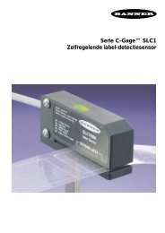
Available <strong>iVu</strong> Brackets<br />
The <strong>iVu</strong> <strong>Plus</strong> TG sensor requires a bracket for mounting. Three brackets are available from<br />
<strong>Banner</strong>. The brackets allow the sensor to be mounted either perpendicular to the part or at<br />
an adjustable angle.<br />
SMBIVURAL SMBIVURAR SMBIVUU<br />
<strong>iVu</strong> <strong>Plus</strong> <strong>Quick</strong> <strong>Start</strong> <strong>Guide</strong><br />
Thread three M4 x 4mm screws through the bracket into the mounting holes in the bottom of the sensor. Tighten all three screws.<br />
10 www.bannerengineering.com - tel: 763-544-3164 154721 rev. C
<strong>iVu</strong> <strong>Plus</strong> <strong>Quick</strong> <strong>Start</strong> <strong>Guide</strong><br />
3.1 <strong>iVu</strong> <strong>Plus</strong> Cable Connections<br />
3.1.1 <strong>iVu</strong> <strong>Plus</strong> with Integrated Display<br />
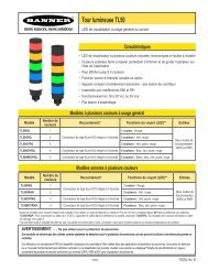
The cable connections on the <strong>iVu</strong> <strong>Plus</strong> with integrated display are shown below, and power I/O connections (C) are defined in the Power<br />
I/O Connections table below.<br />
A B<br />
C<br />
3.1.2 <strong>iVu</strong> <strong>Plus</strong> with Remote Display<br />
A USB Connector<br />
B Ethernet Connector<br />
C Power I/O Connector<br />
NOTE: Microlens model shown, C-Mount model connections are<br />
identical.<br />
The cable connections on the <strong>iVu</strong> <strong>Plus</strong> with remote display are shown below, and power I/O connections (B) are defined in the Power I/O<br />
Connections table below.<br />
A B<br />
C D<br />
A Remote Display Connector<br />
B Power I/O Connector<br />
C USB Connector<br />
D Ethernet Connector<br />
NOTE: Microlens model shown, C-Mount model connections are<br />
identical.<br />
154721 rev. C www.bannerengineering.com - tel: 763-544-3164 11
Power I/O Connections<br />
Pin # Wire Color Description Direction<br />
2 Brown 10-30V dc Input<br />
7 Blue Common (Signal Ground) Input<br />
6 Pink External Trigger Input<br />
5 Gray Remote Teach Input<br />
1 White Output 1 Output<br />
8 Red Ready Output<br />
4 Yellow Strobe Out (5V dc only) Output<br />
3 Green Output 2 Output<br />
9 Orange Output 3 Output<br />
10 Light Blue RS-232 TX Output<br />
11 Black RS-232 Signal Ground Output<br />
12 Violet RS-232 Rx Input<br />
<strong>iVu</strong> <strong>Plus</strong> <strong>Quick</strong> <strong>Start</strong> <strong>Guide</strong><br />
12 www.bannerengineering.com - tel: 763-544-3164 154721 rev. C
4 Overview of Configuring a Sensor<br />
4.1 Acquiring a Good Image<br />
The <strong>iVu</strong> Series sensor needs to capture a good image of each part to ensure that it correctly passes good parts and fails bad parts.<br />
1. Go to Main Menu > Imager > Auto Exposure to run the Auto Exposure routine.<br />
2. Check the lighting.<br />
• Make sure that the lighting is constant and consistent (unchanging over time, no shadows or hot spots).<br />
• Capture the shape and form of the target object with lighting that optimizes its contrast and separates it from the background.<br />
Depending on the target, this may mean the integral ring light is not the best choice and other <strong>Banner</strong> lights should be considered.<br />
• Adjust the mounting angle to provide the clearest image of the part features you are monitoring. The mounting bracket lets you<br />
easily position and adjust the sensor on your line.<br />
3. If needed, go to Main Menu > Imager > Auto Exposure to run the Auto Exposure routine a second time or adjust Gain and<br />
Exposure manually:<br />
• Main Menu > Imager > Gain<br />
• Main Menu > Imager > Exposure<br />
4. Go to Main Menu > Imager > Focus to adjust the focus while monitoring the Focus Number:<br />
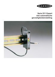
For Micro-lens Models Only:<br />
1. Use the supplied 1/16" hex key to loosen the Focusing Window locking screw (D), then adjust focus on the <strong>iVu</strong> Series sensor using<br />
the clear Focusing Window (B).<br />
2. Adjust focus while monitoring the focus number. To ensure the best image, adjust the focus until<br />
the Focus Number peaks.<br />
NOTE: Turning the Focusing Window counter-clockwise focuses on<br />
closer objects, while turning the Focusing Window clockwise focuses<br />
on more distant objects.<br />
3. Once the best image has been acquired, lock the focusing window.<br />
Micro-Lens Models<br />
A Lens<br />
B Focusing Window<br />
C Locking Clip<br />
D Locking Screw<br />
E Filter Cap (optional)<br />
F Filter (optional)<br />
NOTE: Filter Kits are available separately.<br />
154721 rev. C www.bannerengineering.com - tel: 763-544-3164 13
For C-Mount Models Only:<br />
1. Remove the Lens Enclosure<br />
2. Adjust focus while monitoring the focus number. To ensure the best image, adjust the focus until the Focus Number peaks.<br />
3. Replace the Lens Enclosure on the camera.<br />
C-Mount Models<br />
D C<br />
4.2 Configuring A Sensor Type<br />
4.2.1 Setting External Trigger Mode<br />
A<br />
C<br />
E<br />
B<br />
A C-Mount Lens<br />
B Lens Enclosure<br />
C Retainer Ring (optional)<br />
D Filter (optional)<br />
E Filter Retainer Ring Tool<br />
<strong>iVu</strong> <strong>Plus</strong> <strong>Quick</strong> <strong>Start</strong> <strong>Guide</strong><br />
NOTE: Filter Kits are available separately.<br />
By default the Trigger on the <strong>iVu</strong> <strong>Plus</strong> TG sensor is set to Internal. To maintain control over triggering, before configuring any of the<br />
Sensor Types, change this setting to External ( Main Menu > Imager > Trigger ). Then, use the Manual Trigger in the lower-right corner<br />
of the sreen to trigger the sensor while configuring the sensor.<br />
14 www.bannerengineering.com - tel: 763-544-3164 154721 rev. C
<strong>iVu</strong> <strong>Plus</strong> <strong>Quick</strong> <strong>Start</strong> <strong>Guide</strong><br />
4.2.2 Configuring an Area Sensor<br />
<strong>Start</strong><br />
Select ROI Type and<br />
Adjust<br />
Adjust Intensity Range<br />
Adjust Area Range<br />
Set Pass Count<br />
Use Manual Trigger to Test<br />
Range of Good and Bad<br />
Parts<br />
Finish<br />
NOTE: Make sure you test a<br />
range of samples checking that<br />
the "worst" good part passes, and<br />
the "best" bad part fails.<br />
The flow chart at left provides an overview of the steps to setting up an inspection on the <strong>iVu</strong> <strong>Plus</strong><br />
TG sensor as an Area sensor.<br />
1. Make sure you have a good part to use for the inspection setup. Normally, the part being inspected<br />
is centered in the field of view with the feature of interest surrounded by the Region of<br />
Interest (ROI), the blue rectangle. The ROI can be rotated and resized, and is red when selected<br />
for adjustment.<br />
2. Adjust the ROI so that the part is within the ROI. The pattern will be highlighted in green.<br />
3. Set the following parameters:<br />
NOTE: When running an Area inspection, the sensor will only<br />
find objects within the ROI.<br />
• Intensity Range is the range of gray scale values the sensor should look for. To set the<br />
Intensity Range, use the eye dropper on the left of the screen to select the target feature,<br />
then use the slider bar at the bottom of the display to fine-tune the selection. As the slider<br />
bar is moved, green highlighted areas indicate objects the sensor finds and counts. The<br />
objects colored yellow are found, but filtered out (that is, not counted) because the objects<br />
fall outside of the Area Range.<br />
• The Area Range is used to set the size limits of a feature of interest. Use the slider bar at<br />
the bottom of the display to select the range. Areas are measured by counting pixels. For<br />
example, a rectangular feature that is 100 pixels wide by 200 pixels tall will have an area<br />
of roughly 20,000 pixels.<br />
4. The Minimum Pass Count is the minimum number of parts, labels, or features expected to<br />
fall within the specified criteria; the Maximum Pass Count is the maximum number expected<br />
to fall within the specified criteria. These settings are used to determine the pass or fail result<br />
of the inspection.<br />
5.<br />
Use the Manual Trigger, located in the lower-right corner of the screen, to test good<br />
and bad parts. Adjust settings as necessary and retest.<br />
154721 rev. C www.bannerengineering.com - tel: 763-544-3164 15
4.2.3 Configuring a Blemish Sensor<br />
<strong>Start</strong><br />
Select ROI Type and<br />
Adjust<br />
Adjust Sensitivity<br />
Adjust Edge Length Range<br />
Set Pass Count<br />
Use Manual Trigger to Test<br />
Range of Good and Bad<br />
Parts<br />
Finish<br />
NOTE: Make sure you test a range<br />
of samples checking that the<br />
"worst" good part passes, and the<br />
"best" bad part fails.<br />
The flow chart at left provides an overview of the steps to setting up an inspection on the <strong>iVu</strong> <strong>Plus</strong><br />
TG sensor as a Blemish sensor.<br />
1. Make sure you have a good part to use for the inspection setup. Normally, the part being<br />
inspected is centered in the field of view with the feature of interest surrounded by the Region<br />
of Interest (ROI), the blue rectangle. The ROI can be rotated and resized, and is red<br />
when selected for adjustment.<br />
2. Adjust the ROI so that the part is within the ROI. The pattern will be highlighted in green.<br />
3. Configure the following parameters:<br />
4.<br />
NOTE: When running a Blemish inspection, the sensor will only<br />
find edges within the ROI.<br />
<strong>iVu</strong> <strong>Plus</strong> <strong>Quick</strong> <strong>Start</strong> <strong>Guide</strong><br />
• Sensitivity: Sensitivity is used to fine-tune how sensitive the sensor is to finding blemishes<br />
or other edges within the ROI. The Sensitivity value helps account for light variations<br />
that might affect how well the sensor detects edges. The Sensitivity scale is from 0<br />
to 100 where 0 means least sensitive and 100 means most sensitive. If set near 0, the<br />
sensor will find very sharp edges with strong contrast; if set near 100, the sensor will find<br />
very dim or blurry edges, and may be unstable.<br />
• The Edge Length Range: The sensor counts all the edge pixels it detects in the ROI.<br />
The bar at the bottom of the Edge Length Range screen shows all the different contiguous<br />
edge segments found. Edge segments within the two brackets [ ] are highlighted in<br />
green and those outside the brackets are ignored and colored yellow. You can move<br />
each bracket to add or remove more of the edge segments from consideration.<br />
• Pass Count: The sensor aggregates all the edge pixels that fall within the Edge Length<br />
Range and indicates the value with a small colored bar at the bottom of the page. If within<br />
the range brackets, the bar is green, otherwise it is yellow.<br />
Use the Manual Trigger, located in the lower-right corner of the screen, to test good<br />
and bad parts. Adjust settings as necessary and retest.<br />
16 www.bannerengineering.com - tel: 763-544-3164 154721 rev. C
<strong>iVu</strong> <strong>Plus</strong> <strong>Quick</strong> <strong>Start</strong> <strong>Guide</strong><br />
4.2.4 Configuring a Match Sensor<br />
<strong>Start</strong><br />
Select ROI Type and<br />
Adjust<br />
Click Teach<br />
Click Outside ROI<br />
Adjust Percent Match<br />
(Optional)<br />
Adjust Rotation Range<br />
(Optional)<br />
Set Pass Count<br />
Use Manual Trigger to Test<br />
Range of Good and Bad<br />
Parts<br />
Finish<br />
NOTE: Under normal operation<br />
any parameter modifications take<br />
effect on the next trigger.<br />
The flow chart at left provides an overview of the steps to setting up an inspection on the <strong>iVu</strong> <strong>Plus</strong><br />
TG sensor as a Match sensor.<br />
1. Make sure you use a good part for the inspection setup. Normally, the part will be centered<br />
in the field of view with the feature of interest surrounded by the Region of Interest (ROI), a<br />
blue rectangle. The ROI can be rotated and resized. The ROI turns red when selected for<br />
adjustment.<br />
2. Select the ROI by clicking inside it. Move it, resize it, and rotate it by dragging the ROI or its<br />
corners. Once the feature of interest is within the ROI, click the Teach button. The feature<br />
will be highlighted in green.<br />
3. Configure the following parameters:<br />
4.<br />
NOTE: When running a Match inspection, the sensor will look<br />
for any possible patterns to match anywhere within the field of<br />
view.<br />
• The Percent Match setting adjusts how closely the inspected part or label needs to<br />
match the reference part or label. The Percent Match scale is from 0 to 100, where 0 is<br />
the most tolerant and 100 is the least tolerant. Move the slider to the left or to the right to<br />
adjust the setting. For the best results, use a value from 50 to 90.<br />
NOTE: When running a Match inspection, the sensor will<br />
highlight in green any pattern matches that are within the<br />
specified Rotation Range and meet or exceed the value<br />
specified for Percent Match. Patterns that are within the<br />
specified Rotation Range and within approximately 20% below<br />
the specified value for Percent Match will be colored<br />
yellow.<br />
• The Rotation Range sets the expected rotation of parts or labels during an inspection.<br />
For example, a value of 45 means that the part may rotate 45 degrees in either direction<br />
from the reference part and still pass. Move the slider from 0 to 180 degrees. Note that<br />
the smaller the rotation range, the faster the inspection will run.<br />
• The Minimum Pass Count is the minimum number of parts, labels, or features expected<br />
to fall within the specified criteria; the Maximum Pass Count is the maximum number<br />
expected to fall within the specified criteria. These settings are used to determine the<br />
pass or fail result of the inspection.<br />
Use the Manual Trigger, located in the lower-right corner of the screen, to test good<br />
and bad parts. Adjust settings as necessary and retest.<br />
154721 rev. C www.bannerengineering.com - tel: 763-544-3164 17
4.2.5 Configuring a Sort Sensor<br />
<strong>Start</strong><br />
Select ROI Type and<br />
Adjust<br />
Click Teach<br />
Save Pattern to a Pattern<br />
Slot<br />
Adjust Percent Match<br />
(Optional)<br />
Adjust Rotation Range<br />
(Optional)<br />
Repeat for Next Pattern<br />
Set Pass Criteria for Saved<br />
Patterns<br />
Use Manual Trigger to Test<br />
Finish<br />
NOTE: Under normal operation<br />
any parameter modifications take<br />
effect on the next trigger.<br />
The flow chart at left provides an overview of the steps to set up and inspection on the <strong>iVu</strong> <strong>Plus</strong> TG<br />
sensor as a Sort sensor.<br />
1. Make sure you use good parts for the inspection setup. Normally, each part will be centered<br />
in the field of view with the feature of interest surrounded by the Region of Interest (ROI), a<br />
blue rectangle. The ROI can be rotated and resized, and is red when selected for adjustment.<br />
For the first part, select the ROI by clicking inside it. Move it, resize it, and rotate it by dragging<br />
the ROI or its corners. Once the feature of interest is within the ROI, click the Teach<br />
button. The feature will be highlighted in green.<br />
Tip: Use the short-cut menu in the upper-right of the screen to<br />
select an ROI-type. For better results, make sure that the ROI<br />
bounds the image of the pattern as tightly as possible.<br />
NOTE: When running a Sort inspection, the sensor will look for<br />
any possible patterns to match anywhere within the field of<br />
view.<br />
2. Click the Save button to save the pattern to the first empty pattern storage slot.<br />
3. Set match criteria:<br />
<strong>iVu</strong> <strong>Plus</strong> <strong>Quick</strong> <strong>Start</strong> <strong>Guide</strong><br />
• The Percent Match setting adjusts how closely the inspected part or label needs to<br />
match any of the ten stored patterns. The Percent Match scale is from 0 to 100, where 0<br />
is the most tolerant and 100 is the least tolerant. Move the slider to the left or to the right<br />
to adjust the setting. For the best results, use a value from 50 to 90.<br />
18 www.bannerengineering.com - tel: 763-544-3164 154721 rev. C
<strong>iVu</strong> <strong>Plus</strong> <strong>Quick</strong> <strong>Start</strong> <strong>Guide</strong><br />
NOTE: When running a Sort inspection, the sensor will<br />
highlight in green any pattern matches that are within the<br />
specified Rotation Range and meet or exceed the value<br />
specified for Percent Match. Patterns that are within the<br />
specified Rotation Range and within approximately 20% below<br />
the specified value for Percent Match will be colored<br />
yellow.<br />
• The Rotation Range sets the expected rotation of parts or labels during an inspection.<br />
For example, a value of 45 means that the part may rotate 45 degrees in either direction<br />
from the reference part and still pass. Move the slider from 0 to 180 degrees. Note that<br />
the smaller the rotation range, the faster the inspection will run.<br />
4. Repeat these steps for subsequent patterns and store each pattern in an empty pattern storage<br />
slot.<br />
5. Set the Pass Criteria (assuming only two stored patterns):<br />
6.<br />
• Any Saved Pattern—Pass condition if the sensor matches either Pattern_1, Pattern_2,<br />
or both<br />
• All Saved Patterns—Pass condition if the sensor matches both Pattern_1 AND Pattern_2<br />
• Single Saved Pattern—Pass condition if the sensor matches either Pattern_1 OR Pattern_2,<br />
but NOT both<br />
• Specific Save Pattern (Must also select the saved pattern to match, for example, select<br />
Pattern_2)—Pass condition any time the sensor matches Pattern_2<br />
Use the Manual Trigger, located in the lower-right corner of the screen, to test good<br />
and bad parts. Adjust settings as necessary and retest.<br />
154721 rev. C www.bannerengineering.com - tel: 763-544-3164 19