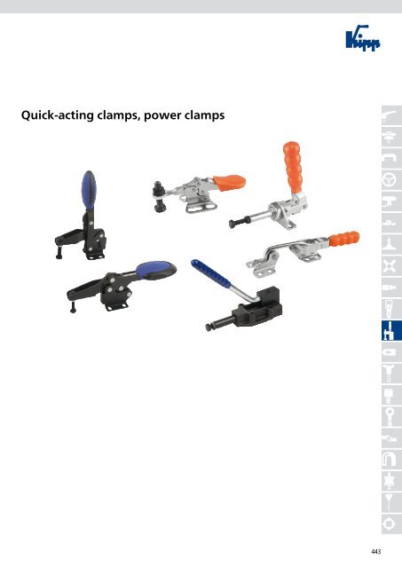
Quick-acting clamps, power clamps
Quick-acting clamps, power clamps
Quick-acting clamps, power clamps

Create successful ePaper yourself
Turn your PDF publications into a flip-book with our unique Google optimized e-Paper software.
<strong>Quick</strong>-<strong>acting</strong> <strong>clamps</strong>, <strong>power</strong> <strong>clamps</strong><br />
443
Product overview<br />
Horizontal toggle <strong>clamps</strong><br />
with flat foot and adjustable<br />
clamping spindle<br />
K0660<br />
Horizontal toggle <strong>clamps</strong><br />
with Safety Interlock with flat<br />
foot and adjustable clamping<br />
spindle<br />
K0660<br />
Horizontal toggle <strong>clamps</strong><br />
with straight foot and adjustable<br />
clamping spindle<br />
K0661<br />
Horizontal Clamps with safety<br />
interlock with straight foot and<br />
adjustable clamping spindle<br />
K0661<br />
Vertical toggle <strong>clamps</strong><br />
with flat foot and adjustable<br />
clamping spindle<br />
K0662<br />
Vertical toggle <strong>clamps</strong> with<br />
safety interlock<br />
with flat foot and adjustable<br />
clamping spindle<br />
K0662<br />
Vertical <strong>clamps</strong><br />
with straight foot and adjustable<br />
clamping spindle<br />
K0663<br />
Vertical <strong>clamps</strong> with safety<br />
interlock<br />
with straight foot and adjustable<br />
clamping spindle<br />
K0663<br />
Nuts<br />
with ball point<br />
K0664<br />
444<br />
<strong>Quick</strong>-<strong>acting</strong> <strong>clamps</strong>, <strong>power</strong> <strong>clamps</strong><br />
¬<br />
Page 450<br />
Page 451<br />
Page 452<br />
Page 453<br />
Page 454<br />
Page 455<br />
Page 456<br />
Page 457<br />
Vertical <strong>clamps</strong><br />
with straight foot and adjustable<br />
clamping spindle<br />
K0055<br />
Vertical <strong>clamps</strong><br />
with straight foot and<br />
fixed clamping spindle<br />
K0056<br />
Vertical <strong>clamps</strong><br />
with flat foot and adjustable<br />
clamping spindle<br />
K0058<br />
Vertical <strong>clamps</strong> with safety<br />
interlock<br />
with flat foot and adjustable<br />
clamping spindle<br />
K0059<br />
Vertical <strong>clamps</strong><br />
with flat foot and fixed<br />
clamping spindle<br />
K0060<br />
Vertical <strong>clamps</strong><br />
with flat foot and full holding arm<br />
K0061<br />
Vertical <strong>clamps</strong><br />
with angled foot and adjustable<br />
clamping spindle<br />
K0062<br />
Vertical <strong>clamps</strong><br />
with angled foot and fixed<br />
clamping spindle<br />
K0063<br />
Vertical <strong>clamps</strong><br />
with angled foot and full<br />
holding arm<br />
K0064<br />
Page 461-462<br />
Page 463<br />
Page 464-465<br />
Page 466<br />
Page 468-469<br />
Page 470<br />
Page 471<br />
Page 472<br />
Page 458 Page 473<br />
new article extended article
Product overview<br />
<strong>Quick</strong>-<strong>acting</strong> <strong>clamps</strong>, <strong>power</strong> <strong>clamps</strong><br />
Vertical curved <strong>clamps</strong><br />
with flat foot<br />
K0065<br />
Vertical <strong>clamps</strong><br />
heavy-duty version with fixed<br />
clamping spindle<br />
K0066<br />
Vertical <strong>clamps</strong><br />
heavy-duty version with full<br />
holding arm<br />
K0067<br />
Horizontal mini-clamp<br />
with straight foot and adjustable<br />
clamping spindle<br />
K0068<br />
Horizontal mini-clamp<br />
with flat foot and adjustable<br />
clamping spindle<br />
K0069<br />
Horizontal mini-clamp<br />
with flat foot and fixed clamping<br />
spindle<br />
K0070<br />
Horizontal mini-clamp<br />
with flat left foot and adjustable<br />
clamping spindle<br />
K0071<br />
Horizontal mini-clamp with flat<br />
right foot and adjustable clamping<br />
spindle<br />
K0267<br />
Horizontal <strong>clamps</strong><br />
with straight foot and adjustable<br />
clamping spindle<br />
K0072<br />
¬<br />
Page 474<br />
Page 475<br />
Page 476<br />
Page 477<br />
Page 478<br />
Page 479<br />
Page 480<br />
Page 481<br />
Horizontal <strong>clamps</strong><br />
with straight foot and full holding<br />
arm<br />
K0073<br />
Horizontal <strong>clamps</strong><br />
with flat foot and adjustable<br />
clamping spindle<br />
K0074<br />
Horizontal <strong>clamps</strong><br />
with flat foot and fixed clamping<br />
spindle<br />
K0075<br />
Horizontal <strong>clamps</strong><br />
with flat foot and full holding<br />
arm<br />
K0076<br />
Horizontal clamp<br />
heavy-duty version with adjustable<br />
clamping spindle<br />
K0077<br />
Tension clamp<br />
K0078<br />
Horizontal hook <strong>clamps</strong><br />
with latch bracket<br />
K0079<br />
Horizontal latch <strong>clamps</strong><br />
with latch bracket<br />
K0080<br />
Horizontal latch <strong>clamps</strong><br />
heavy-duty version with latch<br />
bracket<br />
K0081<br />
Page 483<br />
Page 484<br />
Page 485<br />
Page 486<br />
Page 487<br />
Page 488<br />
Page 489<br />
Page 490<br />
Page 482 Page 491<br />
new article extended article<br />
445
Product overview<br />
Vertical latch <strong>clamps</strong><br />
with latch bracket<br />
K0082<br />
Push-pull mini clamp<br />
with mounting bracket<br />
K0083<br />
Push-pull <strong>clamps</strong><br />
with mounting bracket<br />
K0084<br />
Push-pull <strong>clamps</strong><br />
with mounting bracket<br />
K0085<br />
Push-pull <strong>clamps</strong><br />
without mounting bracket<br />
K0086<br />
Push-pull <strong>clamps</strong><br />
heavy-duty version with handle<br />
K0087<br />
Push-pull <strong>clamps</strong><br />
heavy-duty version with<br />
reversible hand lever<br />
K0088<br />
Horizontal pneumatic <strong>clamps</strong><br />
form A<br />
K0089<br />
446<br />
<strong>Quick</strong>-<strong>acting</strong> <strong>clamps</strong>, <strong>power</strong> <strong>clamps</strong><br />
Horizontal pneumatic <strong>clamps</strong><br />
form B<br />
K0090<br />
¬<br />
Page 492<br />
Page 493<br />
Page 494<br />
Page 495<br />
Page 496<br />
Page 497<br />
Page 498<br />
Page 499<br />
Vertical pneumatic <strong>clamps</strong><br />
heavy-duty version<br />
K0091<br />
Horizontal pneumatic clamp<br />
heavy-duty version<br />
K0092<br />
Pneumatic push-pull <strong>clamps</strong><br />
form A<br />
K0093<br />
Pneumatic push-pull <strong>clamps</strong><br />
form B<br />
K0094<br />
Toggle presses<br />
for manual operation<br />
K0095<br />
Toggle presses for<br />
pneumatic operation<br />
K0096<br />
Angle brackets<br />
K0098<br />
Round plastic grips<br />
K0099<br />
Rectangular plastic grips<br />
K0100<br />
Page 501<br />
Page 502<br />
Page 503<br />
Page 504<br />
Page 505<br />
Page 506<br />
Page 507<br />
Page 508<br />
Page 500 Page 509<br />
new article extended article
Product overview<br />
Pressure bolts<br />
with thrust member<br />
K0688<br />
¬<br />
Pressure bolts<br />
with thrust member<br />
K0689<br />
¬<br />
Neoprene pressure screws<br />
K0690<br />
¬<br />
Rigid clamping spindles<br />
K0101<br />
Clamping spindles<br />
with swivel foot<br />
K0102<br />
Clamping spindles<br />
with vulcanized neoprene<br />
pressure pad<br />
K0103<br />
Neoprene pressure pads<br />
K0104<br />
Plastic covers<br />
K0105<br />
Protective caps<br />
K0106<br />
<strong>Quick</strong>-<strong>acting</strong> <strong>clamps</strong>, <strong>power</strong> <strong>clamps</strong><br />
¬<br />
Page 510<br />
Page 511<br />
Page 512<br />
Page 513<br />
Page 514<br />
Page 515<br />
Page 516<br />
Page 517<br />
Page 517<br />
Locking washers for<br />
clamping spindles<br />
K0107<br />
new article extended article<br />
Page 518<br />
447
448
Technical information<br />
<strong>Quick</strong> clamping - reliable fixing<br />
Durable and reliable: KIPP lock<br />
Now even more durable, more user-friendly and safer. The new generation<br />
has proved highly effective in meeting this development. You, the user,<br />
will notice the difference immediately: On first contact, the new KIPP lock<br />
has a good grip and is robust. It delivers fast, reliable and safe operation.<br />
High-quality material ensures the necessary holding <strong>power</strong>.<br />
with all the advantages<br />
Advantages:<br />
Impressively stable:<br />
All models can easily withstand 300,000 clamping cycles<br />
Durable:<br />
High-quality bushings - without scoring<br />
Extremely robust:<br />
Corrosion-resistant NITROX COATING<br />
Playfully easy:<br />
The fixed headed nut facilitates spindle adjustment<br />
Reliable:<br />
Constant use of force when opening and closing<br />
Ideal where space is restricted:<br />
Slim design supports safe operation<br />
Optimum stability:<br />
Conical clamping arm with U-profile<br />
Safe application:<br />
Nothing can get caught on the smooth edges<br />
Fast and flexible:<br />
Can be easily retrofitted thanks to a wide range of accessories<br />
Ergonomic and slip-resistant:<br />
Easy to operate wearing work gloves<br />
Free of reflection:<br />
Ideal for use with laser devices<br />
Safe when opening:<br />
More freedom between clamping arm and grip prevents squashing<br />
Extremely compatible:<br />
Oblong holes allows assembly on existing boreholes<br />
Secure attachment and locking: KIPP lock+<br />
The inner locking system is a completely revolutionary development from<br />
KIPP. Nothing gets caught or stuck. Operation is easy even when wearing<br />
work gloves.<br />
with all the advantages<br />
with safety interlock<br />
Functional principle:<br />
Fig. 1:<br />
Locking mechanism closed. Harmless to use thanks to revolutionary<br />
grip - no clamping points and interfering contours<br />
Fig. 2:<br />
Inner rod locking mechanism with automatic safety catch. The lock is<br />
released by pulling the grip<br />
Fig. 3:<br />
Locking mechanism open<br />
Release the grip to close the safety mechanism<br />
449
A4<br />
C2<br />
450<br />
K0660<br />
Horizontal toggle <strong>clamps</strong><br />
with flat foot and adjustable clamping spindle<br />
B<br />
D<br />
A2<br />
H1<br />
B4<br />
B2<br />
B3<br />
C M<br />
A3<br />
A<br />
L1<br />
B4<br />
B<br />
A2<br />
hole arrangement for<br />
Order No. K0660.004001<br />
C2<br />
A2<br />
A1<br />
D<br />
A<br />
L<br />
A3<br />
A<br />
D<br />
hand force<br />
B<br />
hole arrangement for<br />
Order No. K0660.005001<br />
H<br />
B<br />
B4<br />
D<br />
A3<br />
A<br />
B6<br />
B1<br />
B5<br />
A4<br />
C2<br />
A2<br />
hole arrangement for<br />
Order No. K0660.012001<br />
KIPP Horizontal toggle <strong>clamps</strong> with flat foot and adjustable clamping spindle<br />
Material:<br />
Steel;<br />
polyamide handle element<br />
Surface finish:<br />
Nitro-carburized and black oxidized<br />
Sample order:<br />
K0660.005001<br />
Note:<br />
Maintenance-free, high-quality swivel bushings.<br />
Consistently constant use of force when opening and<br />
closing. Optimum stability is achieved through the<br />
conical clamping arm with U-profile.<br />
See K0106, K0098, K0383, K0388, K0390, K0391,<br />
K0392, K0393 for accessories.<br />
Angle bracket for head end<br />
mounting (see accessories)<br />
Order No. Opening angle Opening angle Hand force Holding force Holding force Clamping force Clamping force<br />
of holding arm of handle N F1 F2 F3 F4<br />
N N N N<br />
K0660.004001 86° 69° 80 400 500 250 300<br />
K0660.005001 86° 66° 100 650 900 550 620<br />
K0660.006001 87° 68° 160 1350 1900 720 1200<br />
K0660.008001 86° 66° 200 2000 2800 830 1400<br />
K0660.010001 90° 71° 250 2200 4500 1200 2800<br />
K0660.012001 88° 68° 280 2400 5500 1000 2800<br />
Order No. M A A1 A2 A3 A4 B B1 B2 B3 B4 B5 B6 C C2 D H H1 L L1<br />
K0660.004001 M4x16 16 24 4 12,74 1,75 16 24 10,2 7,1 14,1 1,5 20 11,7 5,75 4,2 29,3 26,3 91,8 23,7<br />
K0660.005001 M5x25 18 27 4,5 13,5 - 16,8 27 13,2 9,1 - 2 22,5 18 5,1 5,5 43,4 38,9 126,3 42,6<br />
K0660.006001 M6x35 26 39 6,5 - - 28 39 17,5 12,4 24,6 2,5 43,5 25,5 - 5,5 63,2 59,5 186,7 60,5<br />
K0660.008001 M8x45 26 44 9 - - 31 45 21 15,7 26,1 2,5 41,5 32,2 - 6,2 73,9 70 223,2 74,9<br />
K0660.010001 M10x55 41,5 59 9 - - 43 59 26 18,7 39 3,5 47 40 - 8,8 94,8 87,9 279,4 103,9<br />
K0660.012001 M12x70 44 65 10 40 1 42 67 28 20,9 40 3,5 47 52,3 13,5 8,5 104,8 101,6 314,7 122
B<br />
K0660<br />
Horizontal toggle <strong>clamps</strong><br />
with safety interlock with flat foot and adjustable clamping spindle<br />
H1<br />
B4<br />
B2<br />
B3<br />
C M<br />
L1<br />
A2<br />
B<br />
B4<br />
D<br />
A1<br />
D<br />
A<br />
A3<br />
A<br />
L<br />
A4<br />
C2<br />
A2<br />
hole arrangement for<br />
Order No. K0660.012101<br />
KIPP Horizontal Clamps with safety interlock, with flat foot and adjustable clamping spindle<br />
hand force<br />
H<br />
Order No. Opening angle Opening angle Hand force Holding force Holding force Clamping force Clamping force<br />
of holding arm of handle N F1 F2 F3 F4<br />
N N N N<br />
K0660.006101 87° 68° 160 1350 1900 720 1200<br />
K0660.008101 86° 66° 200 2000 2800 830 1400<br />
K0660.010101 90° 71° 250 2200 4500 1200 2800<br />
K0660.012101 88° 68° 280 2400 5500 1000 2800<br />
Order No. M A A1 A2 A3 A4 B B1 B2 B3 B4 B5 B6 C C2 D H H1 L L1<br />
K0660.006101 M6x35 26 39 6,5 - - 28 39 17,5 12,4 24,6 2,5 53,4 25,5 - 5,5 63,3 59,5 193,3 60,5<br />
K0660.008101 M8x45 26 44 9 - - 31 45 21 15,7 26,1 2,5 51,1 32,2 - 6,2 73,9 70 230,3 74,9<br />
K0660.010101 M10x55 41,5 59 9 - - 43 59 26 18,7 39 3,5 56,5 40 - 8,8 94,8 87,9 286 103,9<br />
K0660.012101 M12x70 44 65 10 40 1 42 67 28 20,9 40 3,5 56,5 52,3 13,5 8,5 104,9 101,6 321,3 122<br />
B6<br />
B1<br />
B5<br />
Material:<br />
Steel;<br />
polyamide handle element;<br />
TPE unlocking bracket<br />
Surface finish:<br />
Nitro-carburized and black oxidized<br />
Sample order:<br />
K0660.006101<br />
Note:<br />
Maintenance-free, high-quality swivel bushings.<br />
Consistently constant use of force when opening and<br />
closing. Optimum stability is achieved through the<br />
conical clamping arm with U-profile. Includes an<br />
internal bar lock with automatic safety.<br />
See K0106, K0098, K0383, K0388, K0390, K0391,<br />
K0392, K0393 for accessories.<br />
451
452<br />
K0661<br />
Horizontal toggle <strong>clamps</strong><br />
with straight foot and adjustable clamping spindle<br />
H1<br />
C<br />
C2<br />
B2<br />
B3<br />
C2<br />
A2<br />
M<br />
L1<br />
A3<br />
A<br />
A2<br />
A<br />
A1<br />
D<br />
hole arrangement for<br />
Order No. K0661.005001<br />
L<br />
A4<br />
D<br />
C2<br />
hand force<br />
A4<br />
A2<br />
D<br />
H<br />
D<br />
A3<br />
A<br />
A4<br />
B6<br />
B<br />
C2<br />
hole arrangement for<br />
Order No. K0661.012001<br />
KIPP Horizontal toggle <strong>clamps</strong> with straight foot and adjustable clamping spindle<br />
B1<br />
Material:<br />
Steel;<br />
polyamide handle element<br />
Surface finish:<br />
Nitro-carburized and black oxidized<br />
Sample order:<br />
K0661.005001<br />
Note:<br />
Maintenance-free, high-quality swivel bushings.<br />
Consistently constant use of force when opening and<br />
closing. Optimum stability is achieved through the<br />
conical clamping arm with U-profile.<br />
See K0106, K0098, K0383, K0388, K0390, K0391,<br />
K0392, K0393 for accessories.<br />
Order No. Opening angle Opening angle Hand force Holding force Holding force Clamping force Clamping force<br />
of holding arm of handle N F1 F2 F3 F4<br />
N N N N<br />
K0661.005001 86° 66° 100 650 900 550 620<br />
K0661.006001 87° 68° 160 1350 1900 720 1200<br />
K0661.008001 86° 66° 200 2000 2800 830 1400<br />
K0661.010001 90° 71° 250 2200 4500 1200 2800<br />
K0661.012001 88° 68° 280 2400 5500 1000 2800<br />
Order No. M A A1 A2 A3 A4 B B1 B2 B3 B6 C C2 D H H1 L L1<br />
K0661.005001 M5x25 18 27 4,5 13,5 - 8,1 4,1 13,2 9,1 22,5 26 5,1 5,5 51,8 47,7 125,7 41,8<br />
K0661.006001 M6x35 26 39 6,5 - 2,5 14,1 9,1 17,5 12,4 43,5 37 5,5 5,5 74,2 71 186,8 60,5<br />
K0661.008001 M8x45 26 44 9 - 3,5 14,1 9,1 21 15,7 41,5 46,5 7 6,2 88,2 84,4 223,5 74,9<br />
K0661.010001 M10x55 41,5 59 9 - 2 16,2 9,2 26 18,7 47 59,6 8 8,8 114,4 107,5 279,3 103,9<br />
K0661.012001 M12x70 44 65 11 40 1 16,2 9,2 28 20,9 47 75,9 13,5 8,5 128,4 125,2 314,7 122
K0661<br />
Horizontal Clamps with safety interlock<br />
with straight foot and adjustable clamping spindle<br />
H1<br />
C<br />
B2<br />
C2<br />
B3<br />
M<br />
C2<br />
L1<br />
A4<br />
A2<br />
A2<br />
D<br />
A<br />
A1<br />
D<br />
A3<br />
A<br />
L<br />
A4<br />
D<br />
A4<br />
hand force<br />
C2<br />
hole arrangement for<br />
Order No. K0661.012101<br />
KIPP Horizontal toggle <strong>clamps</strong> with safety interlock with straight foot and adjustable clamping spindle<br />
H<br />
Order No. Opening angle Opening angle Hand force Holding force Holding force Clamping force Clamping force<br />
of holding arm of handle N F1 F2 F3 F4<br />
N N N N<br />
K0661.006101 87° 68° 160 1350 1900 720 1200<br />
K0661.008101 86° 66° 200 2000 2800 830 1400<br />
K0661.010101 90° 71° 250 2200 4500 1200 2800<br />
K0661.012101 88° 68° 280 2400 5500 1000 2800<br />
Order No. M A A1 A2 A3 A4 B B1 B2 B3 B6 C C2 D H H1 L L1<br />
K0661.006101 M6x35 26 39 6,5 - 2,5 14,1 9,1 17,5 12,4 53,4 37 5,5 5,5 74,3 71 193,7 60,5<br />
K0661.008101 M8x45 26 44 9 - 3,5 14,1 9,1 21 15,7 51,1 46,5 7 6,2 88,3 84,4 230,3 74,9<br />
K0661.010101 M10x55 41,5 59 9 - 2 16,2 9,2 26 18,7 56,5 59,6 8 8,8 114,4 107,5 286,4 103,9<br />
K0661.012101 M12x70 44 65 10 40 1 16,2 9,2 28 20,9 56,5 75,9 13,5 8,5 128,5 125,2 321,3 122<br />
B6<br />
B<br />
B1<br />
Material:<br />
Steel;<br />
polyamide handle element;<br />
TPE unlocking bracket<br />
Surface finish:<br />
Nitro-carburized and black oxidized<br />
Sample order:<br />
K0661.006101<br />
Note:<br />
Maintenance-free, high-quality swivel bushings.<br />
Consistently constant use of force when opening and<br />
closing. Optimum stability is achieved through the<br />
conical clamping arm with U-profile. Includes an<br />
internal bar lock with automatic safety.<br />
See K0106, K0098, K0383, K0388, K0390, K0391,<br />
K0392, K0393 for accessories.<br />
453
454<br />
K0662<br />
Vertical toggle <strong>clamps</strong><br />
with flat foot and adjustable clamping spindle<br />
C<br />
B2<br />
B3<br />
M<br />
D<br />
A3 A3<br />
A3<br />
A2 A2 A2<br />
A<br />
L1 A1<br />
B4<br />
B<br />
hole arrangement for<br />
Order No. K0662.005001<br />
L<br />
hand force<br />
stop pin position 1<br />
stop pin position 2<br />
B6<br />
D<br />
B<br />
A A<br />
hole arrangement for<br />
Order No. K0662.006001<br />
Order No. K0662.008001<br />
D D<br />
D<br />
B1<br />
B4<br />
B<br />
A2<br />
hole arrangement for<br />
Order No. K0662.010001<br />
KIPP Vertical toggle <strong>clamps</strong> with flat foot and adjustable clamping spindle<br />
H<br />
A<br />
B<br />
hole arrangement for<br />
Order No. K0662.012001<br />
Material:<br />
Steel;<br />
polyamide handle element<br />
Surface finish:<br />
Nitro-carburized and black oxidized<br />
Sample order:<br />
K0662.005001<br />
Note:<br />
Maintenance-free, high-quality swivel bushings.<br />
Consistently constant use of force when opening and<br />
closing. Optimum stability is achieved through the<br />
conical clamping arm with U-profile.<br />
See K0106, K0098, K0383, K0388, K0390, K0391,<br />
K0392, K0393 for accessories.<br />
Order No. Opening angle Opening angle Opening angle Opening angle Opening angle Opening angle Hand force Holding force Holding force Clamping force Clamping force<br />
holding arm holding arm holding arm handle handle handle N F1 F2 F3 F4<br />
position 1 position 2 stop pin removed position 1 position 2 stop pin removed N N N N<br />
K0662.005001 100° - 131° 64° - 76° 100 750 1050 620 750<br />
K0662.006001 56° 83° 156° 46° 56° 84° 160 1350 1650 920 1050<br />
K0662.008001 13° 93° 157° 26° 61° 86° 190 2000 2800 940 1350<br />
K0662.010001 6° 97° 175° 19° 59° 91° 250 2500 4500 1500 2800<br />
K0662.012001 11° 88° 163° 24° 60° 91° 280 3000 5500 1400 2800<br />
Order No. M A A1 A2 A3 B B1 B2 B3 B4 B6 C D H L L1<br />
K0662.005001 M5x25 16 25 4,5 14 24 33 13,2 9,1 22 22,5 19,1 4,5 108,5 66,5 35<br />
K0662.006001 M6x35 14 29 7 12 27 38 17,5 12,4 - 43,5 24,7 5,5 156,2 87,5 53<br />
K0662.008001 M8x45 21 39 9 19 32 45 20,6 15,5 - 41,5 32,7 6,8 183,9 107,5 62<br />
K0662.010001 M10x55 32 50 8 27 45 64 25,5 18,4 38 47 38,7 9 222,9 153 95<br />
K0662.012001 M12x70 32 53 10,5 - 45 63 28 20,9 - 47 46,7 8,8 242,4 173,5 113,5
K0662<br />
Vertical toggle <strong>clamps</strong> with safety interlock<br />
with flat foot and adjustable clamping spindle<br />
B2<br />
C<br />
B3<br />
M<br />
A3<br />
L1 A1<br />
D<br />
A2 A2<br />
L<br />
B<br />
A3<br />
A A<br />
hole arrangement for<br />
Order No. K0662.006101<br />
Order No. K0662.008101<br />
hand force<br />
stop pin position 1<br />
stop pin position 2<br />
B6<br />
D D<br />
D<br />
B4<br />
B<br />
A2<br />
hole arrangement for<br />
Order No. K0662.010101<br />
A<br />
B<br />
B1<br />
hole arrangement for<br />
Order No. K0662.012101<br />
KIPP Vertical toggle <strong>clamps</strong> with safety interlock with flat foot and adjustable clamping spindle<br />
Order No. Opening angle Opening angle Opening angle Opening angle Opening angle Opening angle Hand force Holding force Holding force Clamping force Clamping force<br />
holding arm holding arm holding arm handle handle handle N F1 F2 F3 F4<br />
position 1 position 2 stop pin removed position 1 position 2 stop pin removed N N N N<br />
K0662.006101 56° 83° 156° 46° 56° 84° 160 1350 1650 920 1050<br />
K0662.008101 13° 93° 157° 26° 61° 86° 190 2000 2800 940 1350<br />
K0662.010101 6° 97° 175° 19° 59° 91° 250 2500 4500 1500 2800<br />
K0662.012101 11° 88° 163° 24° 60° 91° 280 3000 5500 1400 2800<br />
Order No. M A A1 A2 A3 B B1 B2 B3 B4 B6 C D H L L1<br />
K0662.006101 M6x35 14 29 7 12 27 38 17,5 12,4 - 53,4 24,7 5,5 162,9 87,5 53<br />
K0662.008101 M8x45 21 39 9 19 32 45 20,6 15,5 - 51,1 32,7 6,8 191,4 107,5 62<br />
K0662.010101 M10x55 32 50 8 27 45 64 25,5 18,4 38 56,5 38,7 9 230,5 153 95<br />
K0662.012101 M12x70 32 53 10,5 - 45 63 28 20,9 - 56,5 46,7 8,8 249,1 173,5 113,5<br />
H<br />
Material:<br />
Steel;<br />
polyamide handle element;<br />
TPE unlocking bracket<br />
Surface finish:<br />
Nitro-carburized and black oxidized<br />
Sample order:<br />
K0662.006101<br />
Note:<br />
Maintenance-free, high-quality swivel bushings.<br />
Consistently constant use of force when opening<br />
and closing. Optimum stability is achieved through<br />
the conical clamping arm with U-profile. Includes an<br />
internal bar lock with automatic safety.<br />
See K0106, K0098, K0383, K0388, K0390, K0391,<br />
K0392, K0393 for accessories.<br />
455
456<br />
K0663<br />
Vertical <strong>clamps</strong><br />
with straight foot and adjustable clamping spindle<br />
C<br />
B2<br />
C2<br />
B3<br />
M<br />
L1<br />
A4<br />
A2<br />
A2<br />
L<br />
D<br />
A3<br />
A<br />
A1<br />
D<br />
A3<br />
A<br />
hand force<br />
D<br />
B6<br />
A4<br />
C2<br />
hole arrangement for<br />
Order No. K0663.005001<br />
Order No. K0663.010001<br />
stop pin position 1<br />
stop pin position 2<br />
C2<br />
A2<br />
A<br />
B<br />
D<br />
B1<br />
hole arrangement for<br />
Order No. K0663.012001<br />
KIPP Vertical <strong>clamps</strong> with straight foot and adjustable clamping spindle<br />
Order No. Opening angle Opening angle Opening angle Opening angle Opening angle Hand force Holding force Holding force Clamping force Clamping force<br />
holding arm holding arm holding arm handle handle N F1 F2 F3 F4<br />
position 1 position 2 stop pin removed position 1 position 2 N N N N<br />
K0663.005001 100° - 131° 64° - 100 750 1050 620 750<br />
K0663.006001 56° 83° 156° 46° 56° 160 1350 1650 920 1050<br />
K0663.008001 13° 93° 157° 26° 61° 190 2000 2800 940 1350<br />
K0663.010001 6° 97° 175° 19° 59° 250 2500 4500 1500 2800<br />
K0663.012001 11° 88° 163° 24° 60° 280 3000 5500 1400 2800<br />
Order No. M A A1 A2 A3 A4 B B1 B2 B3 B6 C C2 D H L L1<br />
K0663.005001 M5x25 16 25 4,5 14 1 8,1 4,1 13,2 9,1 22,5 30,8 5,5 4,5 120,3 66,5 35<br />
K0663.006001 M6x35 14 29 7 12 - 10,2 5,2 17,5 12,4 43,5 37,6 5,5 5,5 169,1 87,5 53<br />
K0663.008001 M8x45 21 39 9 19 - 10,2 5,2 20,6 15,5 41,5 49 6,5 6,8 200,1 107,5 62<br />
K0663.010001 M10x55 32 50 8 27 3,5 14,1 7,1 25,5 18,4 47 62,3 13 9 247,4 153 95<br />
K0663.012001 M12x70 32 53 10,5 - - 14,1 7,1 28 20,9 47 69,8 9 8,8 265,5 173,5 113,5<br />
H<br />
Material:<br />
Steel;<br />
polyamide handle element<br />
Surface finish:<br />
Nitro-carburized and black oxidized<br />
Sample order:<br />
K0663.005001<br />
Note:<br />
Maintenance-free, high-quality swivel bushings.<br />
Consistently constant use of force when opening and<br />
closing. Optimum stability is achieved through the<br />
conical clamping arm with U-profile.<br />
See K0106, K0098, K0383, K0388, K0390, K0391,<br />
K0392, K0393 for accessories.
K0663<br />
Vertical <strong>clamps</strong> with safety interlock<br />
with straight foot and adjustable clamping spindle<br />
C<br />
B2<br />
C2<br />
B3<br />
M<br />
L1<br />
A4<br />
A2<br />
L<br />
A2<br />
D<br />
A3<br />
A<br />
A1<br />
D<br />
A3<br />
A<br />
hand force<br />
D<br />
B6<br />
A4<br />
C2<br />
hole arrangement for<br />
Order No. K0663.010101<br />
stop pin position 1<br />
stop pin position 2<br />
C2<br />
A2<br />
A<br />
B<br />
B1<br />
D<br />
H<br />
hole arrangement for<br />
Order No. K0663.012101<br />
Material:<br />
Steel;<br />
polyamide handle element;<br />
TPE unlocking bracket<br />
KIPP Vertical <strong>clamps</strong> with safety interlock, with straight foot and adjustable clamping spindle<br />
Surface finish:<br />
Nitro-carburized and black oxidized<br />
Sample order:<br />
K0663.006101<br />
Note:<br />
Maintenance-free, high-quality swivel bushings.<br />
Consistently constant use of force when opening and<br />
closing. Optimum stability is achieved through the<br />
conical clamping arm with U-profile. Includes an<br />
internal bar lock with automatic safety.<br />
See K0106, K0098, K0383, K0388, K0390, K0391,<br />
K0392, K0393 for accessories.<br />
Order No. Opening angle Opening angle Opening angle Opening angle Opening angle Hand force Holding force Holding force Clamping force Clamping force<br />
holding arm holding arm holding arm handle handle N F1 F2 F3 F4<br />
position 1 position 2 stop pin removed position 1 position 2 N N N N<br />
K0663.006101 56° 83° 156° 46° 56° 160 1350 1650 920 1050<br />
K0663.008101 13° 93° 157° 26° 61° 190 2000 2800 940 1350<br />
K0663.010101 6° 97° 175° 19° 59° 250 2500 4500 1500 2800<br />
K0663.012101 11° 88° 163° 24° 60° 280 3000 5500 1400 2800<br />
Order No. M A A1 A2 A3 A4 B B1 B2 B3 B6 C C2 D H L L1<br />
K0663.006101 M6x35 14 29 7 12 - 10,2 5,2 17,5 12,4 53,4 37,6 5,5 5,5 175,7 87,5 53<br />
K0663.008101 M8x45 21 39 9 19 - 10,2 5,2 20,6 15,5 51,1 49 6,5 6,8 207,6 107,5 62<br />
K0663.010101 M10x55 32 50 8 27 3,5 14,1 7,1 25,5 18,4 56,5 62,3 13 9 254 153 95<br />
K0663.012101 M12x70 32 53 10,5 - - 14,1 7,1 28 20,9 56,5 69,8 9 8,8 271,9 173,5 113,5<br />
457
458<br />
K0664<br />
Nuts<br />
with ball point<br />
SW<br />
D1 H<br />
KIPP Nuts with flat point<br />
R<br />
D<br />
Material:<br />
Steel<br />
Surface finish:<br />
Black oxide finish<br />
Sample order:<br />
K0664.04<br />
suitable for welding<br />
Order No. D H D1 SW R<br />
K0664.04 M4 5,2 8 7 7<br />
K0664.05 M5 6,7 10 9 9<br />
K0664.06 M6 9,5 13,5 12,2 10<br />
K0664.08 M8 12,8 18 15,3 12<br />
K0664.10 M10 12,1 20 18,2 14<br />
K0664.12 M12 14,8 23 20 16
Application example<br />
459
Notes<br />
460
Technical information<br />
Figure 1:<br />
Clamp in end position over dead centre<br />
Self-locking in the clamping joints avoids automatic<br />
opening during the machining process.<br />
Figure 2:<br />
Clamp in intermediate position<br />
The holding arm approaches dead centre of the toggle<br />
joint very rapidly when closing the clamp (swivel angle<br />
of handle
462<br />
K0055<br />
Vertical <strong>clamps</strong><br />
with straight foot and adjustable clamping spindle<br />
hand force<br />
stop pin position 1<br />
stop pin position 2<br />
KIPP Vertical <strong>clamps</strong> with straight foot and adjustable clamping spindle<br />
Material:<br />
Steel<br />
Surface finish:<br />
Galvanized and chromated,<br />
clamping spindle and nuts phosphated,<br />
plastic handle oil-resistant<br />
Sample order:<br />
K0055.0250<br />
Note:<br />
The opening angle between the holding arm and the<br />
handle can be reduced or enlarged by repositioning or<br />
removing the stop pin.<br />
A neoprene pressure pad is supplied with versions<br />
K0055.0075 and K0055.0150.<br />
See K0100, K0101, K0102, K0103, K0106, K0107 for<br />
accessories.<br />
Order No. Opening angle Opening angle Opening angle Opening angle Opening angle Opening angle<br />
holding arm holding arm holding arm handle handle handle<br />
position 1 position 2 stop pin removed position 1 position 2 stop pin removed<br />
K0055.0075 130° - 195° 90° - 125°<br />
K0055.0150 95° - 185° 75° - 110°<br />
K0055.0250 95° 125° 160° 70° 85° 100°<br />
K0055.0350 90° 120° 180° 70° 80° 110°<br />
K0055.0450 90° 125° 180° 70° 85° 110°<br />
K0055.0550 90° 120° 180° 65° 80° 110°<br />
Order No. A A1 A2 B B1 B2 B3 C C1 C2 D H L L1 M Hand force Holding force Holding force Clamping force Clamping force<br />
N F1 F2 F3 F4<br />
N N N N<br />
K0055.0075 16 26 5 8 4 17 5,5 22 9 5 4,4 106 57 31 M5x35 80 700 1100 500 750<br />
K0055.0150 12,7 27 7 12 6 24 6,4 28 11 5,4 5,1 135 70 43 M6x50 120 1350 1650 800 1050<br />
K0055.0250 19 35 8 12 6 26 8,8 39 17,5 7 7,1 190 110 75 M8x60 190 1000 2800 900 1700<br />
K0055.0350 32 50 9 16 8 33 10,6 54 22 9,6 8,3 245 145 95 M10x80 230 2200 4500 1400 3000<br />
K0055.0450 32 53 10 20 10 42 13,5 59 25 8,7 8,7 246 177 124 M12x100 260 3200 7000 1400 3000<br />
K0055.0550 51 76 12,5 20 10 41 16,5 102 32 12,7 12,3 345 230 154 M16x150 290 3000 8000 1800 3900
K0056<br />
Vertical <strong>clamps</strong><br />
with straight foot and fixed clamping spindle<br />
hand force<br />
stop pin position 1<br />
stop pin position 2<br />
KIPP Vertical <strong>clamps</strong> with straight foot and fixed clamping spindle<br />
Material:<br />
Steel<br />
Surface finish:<br />
Galvanized and chromated,<br />
clamping spindle and nuts phosphated,<br />
plastic handle oil-resistant<br />
Sample order:<br />
K0056.0150<br />
Note:<br />
The opening angle between the holding arm and the<br />
handle can be reduced or enlarged by repositioning or<br />
removing the stop pin.<br />
A neoprene pressure pad is supplied with version<br />
K0056.0150.<br />
See K0100, K0101, K0102, K0103, K0106 for<br />
accessories.<br />
Order No. Opening angle Opening angle Opening angle Opening angle Opening angle Opening angle<br />
holding arm holding arm holding arm handle handle handle<br />
position 1 position 2 stop pin removed position 1 position 2 stop pin removed<br />
K0056.0150 95° - 185° 75° - 110°<br />
K0056.0250 95° 125° 160° 70° 85° 100°<br />
K0056.0350 90° 120° 180° 70° 80° 110°<br />
K0056.0450 90° 125° 180° 70° 85° 110°<br />
K0056.0550 90° 120° 180° 65° 80° 110°<br />
Order No. A A1 A2 B B1 B2 C C1 C2 D H L L1 M Hand force Holding force Clamping force<br />
N F1 F3<br />
N N<br />
K0056.0150 12,7 27 7 12 6 24 28 11 5,4 5,1 135 60 26 M6x50 120 1500 900<br />
K0056.0250 19 35 8 12 6 26 37 21,5 7 7,1 190 87 45 M8x60 190 2500 1150<br />
K0056.0350 32 50 9 16 8 33 52 25,5 9,6 8,3 240 124 65 M10x80 230 3500 1650<br />
K0056.0450 32 53 10 20 10 42 57 30 8,7 8,7 246 136 74 M12x100 260 4500 1650<br />
K0056.0550 51 76 12,5 20 10 41 101 38 12,7 12,3 345 197 108 M16x150 290 5500 1900<br />
463
464<br />
K0058<br />
Vertical <strong>clamps</strong><br />
with flat foot and adjustable clamping spindle<br />
hand force<br />
stop pin position 1<br />
stop pin position 2<br />
holding arm open<br />
in Order No.<br />
K0058.0100<br />
K0058.0200<br />
K0058.0300<br />
hole arrangement for hole arrangement for<br />
hole arrangement for<br />
Order No. K0058.0100 Order No. K0058.0200 Order No. K0058.0300<br />
Material:<br />
Steel or stainless steel<br />
Surface finish:<br />
Galvanized and chromated,<br />
clamping spindle and nuts phosphated,<br />
stainless steel natural finish,<br />
plastic handle oil-resistant<br />
Sample order:<br />
K0058.0250N<br />
Note:<br />
The opening angle between the holding arm and the<br />
handle can be reduced or enlarged by repositioning or<br />
removing the stop pin.<br />
A neoprene pressure pad is supplied with versions<br />
K0058.0075, K0058.0100 and K0058.0150.<br />
An angle bracket cannot be supplied in stainless<br />
steel with versions K0058.0075N, K0058.0150N and<br />
K0058.0250N.<br />
See K0098, K0100, K0101, K0102, K0103, K0106,<br />
K0107 for accessories.
K0058<br />
Vertical <strong>clamps</strong><br />
with flat foot and adjustable clamping spindle<br />
KIPP Vertical <strong>clamps</strong> with flat foot and adjustable clamping spindle<br />
Angle bracket for<br />
head end mounting<br />
(see accessories)<br />
Order No. Surface finish Opening angle Opening angle Opening angle Opening angle Opening angle Opening angle Item No.<br />
holding arm holding arm holding arm handle handle handle Angle Bracket<br />
position 1 position 2 stop pin removed position 1 position 2 stop pin removed<br />
K0058.0075 steel 130° - 160° 90° - 100° K0098.02<br />
K0058.0100 steel 95° - 185° 65° - 105° -<br />
K0058.0150 steel 95° - 185° 75° - 110° K0098.02<br />
K0058.0200 steel 105° - 175° 70° - 95° -<br />
K0058.0250 steel 95° 125° 160° 70° 85° 100° K0098.04<br />
K0058.0300 steel 105° - 160° 65° - 90° -<br />
K0058.0350 steel 90° 120° 180° 70° 80° 110° K0098.06<br />
K0058.0450 steel 90° 125° 180° 70° 85° 110° K0098.06<br />
K0058.0550 steel 90° 120° 180° 65° 80° 110° -<br />
K0058.0075N stainless steel 130° - 160° 90° - 100° -<br />
K0058.0150N stainless steel 95° - 185° 75° - 110° -<br />
K0058.0250N stainless steel 95° 125° 160° 70° 85° 100° -<br />
Order No. Surface finish A A1 A2 A3 B B1 B3 B4 C C1 D H L L1 M Hand force Holding force Holding force Clamping force Clamping force<br />
N F1 F2 F3 F4<br />
N N N N<br />
K0058.0075 steel 16 25 5 - 24 34 5,5 - 16 9 4,4 94 57 32 M5x35 80 700 1100 500 750<br />
K0058.0100 steel 16 29 6 14 24 34 5,5 17,5 22 9,5 4,8 98 67 38 M5x35 80 700 1000 500 800<br />
K0058.0150 steel 12,7 27 7 - 27 38 6,4 - 23 11 5,1 121 70 43 M6x50 120 1350 1650 800 1050<br />
K0058.0200 steel 19 35 8 12,7 27 42 6,3 25 30 12,7 5,5 135 79 44 M6x50 100 1000 2200 950 1350<br />
K0058.0250 steel 19 35 8 - 32 45 8,8 - 32 17,5 7,1 175 110 75 M8x60 190 1000 2800 900 1700<br />
K0058.0300 steel 25 43 9 19 34,5 53 8,8 - 34 19 8 186 143 100 M8x60 130 2000 3700 900 1850<br />
K0058.0350 steel 32 50 9 - 45 64 10,6 - 43 22 8,3 220 145 95 M10x80 230 2200 4500 1400 3000<br />
K0058.0450 steel 32 53 10 - 45 64 12,7 - 51 25 8,7 228 177 124 M12x100 260 3200 7000 1400 3000<br />
K0058.0550 steel 51 76 12,5 - 70 95 16,5 - 84 32 12,3 312 232 156 M16x150 290 3000 8000 1800 3900<br />
K0058.0075N stainless steel 16 25 5 - 24 34 5,5 - 16 9 4,4 94 57 32 M5x35 80 700 1100 500 750<br />
K0058.0150N stainless steel 12,7 27 7 - 27 38 6,4 - 23 11 5,1 121 70 43 M6x50 120 1350 1650 800 1050<br />
K0058.0250N stainless steel 19 35 8 - 32 45 8,8 - 32 17,5 7,1 175 110 75 M8x60 190 1000 2800 900 1700<br />
465
466<br />
K0059<br />
Vertical <strong>clamps</strong> with safety interlock<br />
with flat foot and adjustable clamping spindle<br />
C C1<br />
B3<br />
M<br />
L1<br />
A2 A<br />
L<br />
A1<br />
D<br />
hand force<br />
B<br />
stop pin position 2<br />
stop pin position 1<br />
Angle bracket for<br />
head end mounting<br />
(see accessories)<br />
KIPP Vertical <strong>clamps</strong> with safety interlock with flat foot and adjustable clamping spindle<br />
Order No. Opening angle Opening angle Opening angle Opening angle Item No.<br />
holding arm holding arm handle handle Angle Bracket<br />
position 1 position 2 position 1 position 2<br />
K0059.0250 105° 60° 150° 135° K0098.04<br />
K0059.0350 105° 60° 150° 135° K0098.06<br />
Order No. A A1 A2 B B1 B3 C C1 D H L L1 M Holding force Holding force<br />
F1 F2<br />
N N<br />
K0059.0250 20 40,5 7,5 32 44 8 35 18 7,5 185 110,5 70 M8x45 1800 2500<br />
K0059.0350 32 59,5 13 45 64 10 45 20 8,5 206 140 80,5 M8x65 2000 3000<br />
B1<br />
H<br />
Material:<br />
Steel.<br />
Surface finish:<br />
galvanized and chromated<br />
plastic handle oil-resistant.<br />
Sample order:<br />
K0059.0250<br />
Note:<br />
With safety interlock for the clamping point and opened<br />
position. Safety clamping element with finger<br />
protection. Anti-loosening lock for the press-on bolt on<br />
the end of the clamping arm.<br />
The opening angle between the holding arm and the<br />
handle can be reduced by pressing in of the stop pin<br />
(stop position 2).<br />
Clamping spindle with a neoprene pressure pad.<br />
See K0098, K0100, K0101, K0102, K0103, K0106,<br />
K0107 for accessories.
Notes<br />
467
468<br />
K0060<br />
Vertical <strong>clamps</strong><br />
with flat foot and fixed clamping spindle<br />
hand force<br />
stop pin position 1<br />
hole arrangement for<br />
Order No.<br />
hole arrangement for<br />
Order No.<br />
hole arrangement for<br />
Order No.<br />
K0060.0100 K0060.0200 K0060.0300<br />
Material:<br />
Steel<br />
Surface finish:<br />
Galvanized and chromated, clamping spindle and nuts<br />
phosphated, plastic handle oil-resistant<br />
Sample order:<br />
K0060.0250<br />
Note:<br />
The opening angle between the holding arm and the<br />
handle can be reduced or enlarged by repositioning or<br />
removing the stop pin.<br />
A neoprene pressure pad is supplied with version<br />
K0060.0100 and K0060.0150.<br />
See K0098, K0100, K0101, K0102, K0103, K0106 for<br />
accessories.
K0060<br />
Vertical <strong>clamps</strong><br />
with flat foot and fixed clamping spindle<br />
KIPP Vertical <strong>clamps</strong> with flat foot and fixed clamping spindle<br />
Angle bracket for<br />
head end mounting<br />
(see accessories)<br />
Order No. Opening angle Opening angle Opening angle Opening angle Hand force Holding force Clamping force<br />
holding arm holding arm handle handle N F1 F3<br />
position 1 stop pin removed position 1 stop pin removed N N<br />
K0060.0100 95° 185° 65° 105° 80 850 650<br />
K0060.0150 95° 185° 75° 110° 120 1500 900<br />
K0060.0200 105° 175° 70° 95° 100 1600 1150<br />
K0060.0250 95° 160° 70° 100° 190 2500 1150<br />
K0060.0300 105° 160° 65° 90° 130 3000 1150<br />
K0060.0350 90° 180° 70° 110° 230 3500 1650<br />
K0060.0450 90° 180° 70° 110° 260 4500 1650<br />
K0060.0550 90° 180° 65° 110° 290 5500 1900<br />
Order No. A A1 A2 A3 B B1 B4 C C1 D H L L1 M Item No.<br />
Angle Bracket<br />
K0060.0100 16 28 6 14 24 34 17,5 22 9,5 4,8 103 65 32 M5x35 -<br />
K0060.0150 12,7 27 7 - 27 38 - 23 11 5,1 125 60 26 M6x50 K0098.02<br />
K0060.0200 19 35 8 12,7 27 42 25 29 12,7 5,5 135 77 37 M6x50 -<br />
K0060.0250 19 35 8 - 32 47 - 29 21,5 7,1 175 87 45 M8x60 K0098.04<br />
K0060.0300 25 43 9 19 34,5 52 - 32 21,5 8 186 115 65 M8x60 -<br />
K0060.0350 32 50 9 - 45 64 - 40 25,5 8,3 220 123 65 M10x80 K0098.06<br />
K0060.0450 32 53 10 - 45 64 - 47 30 8,7 228 136,5 74 M12x100 K0098.06<br />
K0060.0550 51 76 12,5 - 70 95 - 81 38 12,3 312 196,5 108 M16x150 -<br />
469
hole arrangement for<br />
Order No.<br />
K00061.0300<br />
470<br />
K0061<br />
Vertical <strong>clamps</strong><br />
with flat foot and full holding arm<br />
hand force<br />
stop pin position 1<br />
stop pin position 2<br />
KIPP Vertical <strong>clamps</strong> with flat foot and full holding arm<br />
spindle clamp can<br />
be welded on<br />
Material:<br />
Steel<br />
Surface finish:<br />
Galvanized and chromated, plastic handle oil-resistant<br />
Sample order:<br />
K0061.0550<br />
Note:<br />
The opening angle between the holding arm and the<br />
handle can be reduced or enlarged by repositioning or<br />
removing the stop pin.<br />
See K0098, K0100, K0101, K0102, K0103, K0106 for<br />
accessories.<br />
Angle bracket for<br />
head end mounting<br />
(see accessories)<br />
Order No. Opening angle Opening angle Opening angle Opening angle Opening angle Opening angle Item No.<br />
holding arm holding arm holding arm handle handle handle Angle Bracket<br />
position 1 position 2 stop pin removed position 1 position 2 stop pin removed<br />
K0061.0250 95° 125° 160° 70° 85° 100° K0098.04<br />
K0061.0300 105° - 160° 65° - 90° -<br />
K0061.0350 90° 120° 180° 70° 80° 110° K0098.06<br />
K0061.0450 90° 125° 180° 70° 85° 110° K0098.06<br />
K0061.0550 90° 120° 180° 65° 80° 110° -<br />
Order No. A A1 A2 A3 B B1 B3 C C1 C3 D D1 E H L L1 Clamping Hand Holding force Holding force Clamping force Clamping force<br />
spindle force F1 F2 F3 F4<br />
N N N N N<br />
K0061.0250 19 35 8 - 32 47 6 31 17,5 17,5 7,1 8,3 24 175 112 77 M8x60 190 1000 2800 900 1700<br />
K0061.0300 25 43 9 19 34,5 52 6 34 19 17,5 8 8,3 24 186 143 100 M8x60 130 2000 3700 900 1850<br />
K0061.0350 32 50 9 - 45 64 8 42 22 22 8,3 10,3 30 220 149 99 M10x80 230 2200 4500 1400 3000<br />
K0061.0450 32 53 10 - 45 64 10 51 25 26 8,7 12,3 32 228 180 127 M12x100 260 3200 7000 1400 3000<br />
K0061.0550 51 76 12,5 - 70 95 10 84 32 32 12,3 16,3 35 312 236 160 M16x150 290 3000 8000 1800 3900
K0062<br />
Vertical <strong>clamps</strong><br />
with angled foot and adjustable clamping spindle<br />
hand force<br />
stop pin position 1<br />
hole arrangement<br />
for Order No.<br />
K0062.0100<br />
K0062.0200<br />
KIPP Vertical <strong>clamps</strong> with angled foot and adjustable clamping spindle<br />
Material:<br />
Steel<br />
Surface finish:<br />
Galvanized and chromated,<br />
clamping spindle and nuts phosphated,<br />
plastic handle oil-resistant<br />
Sample order:<br />
K0062.0200<br />
Note:<br />
The opening angle between the holding arm and the<br />
handle can be reduced or enlarged by repositioning or<br />
removing the stop pin.<br />
A neoprene pressure pad is supplied with version<br />
K0062.0100.<br />
See K0100, K0101, K0102, K0103, K0106, K0107 for<br />
accessories.<br />
Order No. Opening angle Opening angle Opening angle Opening angle<br />
holding arm holding arm handle handle<br />
position 1 stop pin removed position 1 stop pin removed<br />
K0062.0100 80° 190° 60° 100°<br />
K0062.0200 105° 175° 70° 95°<br />
K0062.0300 105° 160° 65° 90°<br />
Order No. A A1 A2 A3 B B1 B3 C C1 D H L L1 L2 M Hand force Holding force Holding force Clamping force Clamping force<br />
N F1 F2 F3 F4<br />
N N N N<br />
K0062.0100 14 29 7,5 - 17,5 28 5,5 44 9,5 4,8 122 67 31 36 M5x35 80 700 1000 500 800<br />
K0062.0200 19 35 8 - 26 42 6,3 64 12,7 5,5 170 79 35 44 M6x50 100 1000 2200 950 1350<br />
K0062.0300 35 51 8 16 35 51 8,8 82 19 6,8 235 143 92 51 M8x60 130 2000 3700 900 1850<br />
471
472<br />
K0063<br />
Vertical <strong>clamps</strong><br />
with angled foot and fixed clamping spindle<br />
hand force<br />
stop pin position 1<br />
hole arrangement<br />
for Order No.<br />
K0063.0100<br />
K0063.0200<br />
KIPP Vertical <strong>clamps</strong> with angled foot and fixed clamping spindle<br />
Material:<br />
Steel<br />
Surface finish:<br />
Galvanized and chromated,<br />
clamping spindle and nuts phosphated,<br />
plastic handle oil-resistant<br />
Sample order:<br />
K0063.0100<br />
Note:<br />
The opening angle between the holding arm and the<br />
handle can be reduced or enlarged by repositioning or<br />
removing the stop pin.<br />
A neoprene pressure pad is supplied with version<br />
K0063.0100.<br />
See K0100, K0101, K0102, K0103, K0106 for<br />
accessories.<br />
Order No. Opening angle Opening angle Opening angle Opening angle<br />
holding arm holding arm handle handle<br />
position 1 stop pin removed position 1 stop pin removed<br />
K0063.0100 80° 190° 60° 100°<br />
K0063.0200 105° 175° 70° 95°<br />
K0063.0300 105° 160° 65° 90°<br />
Order No. A A1 A2 A3 B B1 C C1 D H L L1 L2 M Hand force Holding force Clamping force<br />
N F1 F3<br />
N N<br />
K0063.0100 14 29 7 - 17,5 28 44 9,5 4,8 122 66 24,5 36 M5x35 80 850 650<br />
K0063.0200 19 35 8 - 25 41 64 12,7 5,5 170 77 27 44 M6x50 100 1600 1150<br />
K0063.0300 35 51 8 16 35 51 81 21,5 6,8 235 116 58 51 M8x60 130 3000 1150
K0064<br />
Vertical <strong>clamps</strong><br />
with angled foot and full holding arm<br />
hand force<br />
stop pin position 1<br />
spindle clamp can be welded on<br />
KIPP Vertical <strong>clamps</strong> with angled foot and full holding arm<br />
Material:<br />
Steel<br />
Surface finish:<br />
Galvanized and chromated, plastic handle oil-resistant<br />
Sample order:<br />
K0064.0300<br />
Note:<br />
The opening angle between the holding arm and the<br />
handle can be reduced or enlarged by repositioning or<br />
removing the stop pin.<br />
See K0100, K0101, K0102, K0103, K0106 for<br />
accessories.<br />
Order No. Opening angle Opening angle Opening angle Opening angle<br />
holding arm holding arm handle handle<br />
position 1 stop pin removed position 1 stop pin removed<br />
K0064.0300 105° 160° 65° 90°<br />
Order No. A A1 A2 A3 B B1 B3 C C1 C3 D D1 E H L L1 L2 Clamping Hand force Holding force Holding force Clamping force Clamping force<br />
spindle N F1 F2 F3 F4<br />
N N N N<br />
K0064.0300 35 51 8 16 35 51 6 82 19 17,5 6,8 8,3 24 235 143 92 51 M8x60 130 2000 3700 900 1850<br />
473
474<br />
K0065<br />
Vertical curved <strong>clamps</strong><br />
with flat foot<br />
hand force<br />
KIPP Vertical curved <strong>clamps</strong> with flat foot<br />
Material:<br />
Steel<br />
Surface finish:<br />
Galvanized and chromated,<br />
clamping spindle and nuts phosphated,<br />
plastic handle oil-resistant<br />
Sample order:<br />
K0065.0075<br />
Note:<br />
The curved <strong>clamps</strong> are ideal for clamping workpieces<br />
with a relatively large tolerance such as casting blanks<br />
or nonferrous metals.<br />
See K0098, K0100, K0101, K0102, K0103, K0106 for<br />
accessories.<br />
Angle bracket for<br />
head end mounting<br />
(see accessories)<br />
Order No. Opening angle Opening angle Hand force Holding force Clamping force<br />
of holding arm of handle N F1 F3<br />
N N<br />
K0065.0075 90° 80° 190 750 350 - 600<br />
K0065.0250 85° 80° 190 2500 850 - 1200<br />
K0065.0350 90° 80° 230 3500 950 - 1400<br />
Order No. A A1 A2 B B1 C C1 D H L L1 L2 M Item No.<br />
Angle Bracket<br />
K0065.0075 16 26 5 24 34 16 9,5 4,4 93 52 22 7 M5x35 K0098.02<br />
K0065.0250 19 35 8 32 47 30 21,5 7,1 176 74 32 20 M8x60 K0098.04<br />
K0065.0350 32 50 9 45 64 42 25,5 8,3 220 116 59 13 M10x80 K0098.06
K0066<br />
Vertical <strong>clamps</strong><br />
heavy-duty version with fixed clamping spindle<br />
hand force<br />
adjustable<br />
holding arm<br />
guide<br />
KIPP Vertical <strong>clamps</strong> heavy-duty version with fixed clamping spindle<br />
Material:<br />
Steel<br />
Surface finish:<br />
Black oxide finish, clamping spindle and nuts<br />
phosphated, bearing pins and bearing sleeves<br />
case-hardened, plastic handle oil-resistant<br />
Sample order:<br />
K0066.2400<br />
Note:<br />
Oil all joints regularly.<br />
See K0099, K0101, K0102, K0103, K0106<br />
for accessories.<br />
Order No. Opening angle Opening angle Hand force Holding force Clamping force<br />
of holding arm of handle N F1 F3<br />
N N<br />
K0066.0700 180° 120° 340 6000 1400<br />
K0066.1200 180° 125° 500 8000 1400<br />
K0066.2400 195° 130° 500 15000 1850<br />
Order No. A A1 A2 A3 B B1 B3 C C1 D H L L1 L2 M S<br />
K0066.0700 25 45 10 25 50 68 10 45 30 8,3 215 124 50 20 M12x100 5<br />
K0066.1200 30 51 10 25 60 86,5 12 58 30 8,3 250 144 60 23 M12x100 6<br />
K0066.2400 40 64 12 40 75 103 16 70 38 10,3 295 188 75 37 M16x150 8<br />
475
476<br />
K0067<br />
Vertical <strong>clamps</strong><br />
heavy-duty version with full holding arm<br />
hand force<br />
adjustable<br />
holding<br />
arm guide<br />
sleeve with hexagon screw<br />
and nuts<br />
KIPP Vertical <strong>clamps</strong>, heavy-duty version with full holding arm<br />
Material:<br />
Steel<br />
Surface finish:<br />
Black oxide finish, bearing pins and bearing sleeves<br />
case-hardened, plastic handle oil-resistant<br />
Sample order:<br />
K0067.1200<br />
Note:<br />
Oil all joints regularly.<br />
See K0099, K0101, K0102, K0103, K0106 for<br />
accessories.<br />
Order No. Opening angle Opening angle Hand force Holding force Clamping force<br />
of holding arm of handle N F1 F3<br />
N N<br />
K0067.0700 205° 130° 340 7000 1400<br />
K0067.1200 195° 130° 500 12000 1400<br />
K0067.2400 195° 130° 500 15000 1850<br />
Order No. A1 A3 B B1 B2 B3 C C1 C4 D H L L1 L2 M<br />
K0067.0700 45 25 20 10 43 10 70 22 50 12,2 235 104 40 30 M12x100<br />
K0067.1200 51 26 24 12 51 12 88 26 63 12,2 276 124 50 30 M12x100<br />
K0067.2400 64 40 32 16 64 16 105 32 76 16,3 318 162 60 38 M16x150
K0068<br />
Horizontal mini-clamp<br />
with straight foot and adjustable clamping spindle<br />
hand force<br />
KIPP Horizontal mini-clamp with straight foot and adjustable clamping spindle<br />
Material:<br />
Steel<br />
Surface finish:<br />
Galvanized and chromated,<br />
clamping spindle and nuts phosphated,<br />
plastic handle oil-resistant<br />
Sample order:<br />
K0068.0050<br />
Note:<br />
See K0101, K0102, K0103, K0106, K0107 for<br />
accessories.<br />
Order No. Opening angle Opening angle Hand force Holding force Holding force Clamping force Clamping force<br />
of holding arm of handle N F1 F2 F3 F4<br />
N N N N<br />
K0068.0050 85° 65° 80 250 550 170 370<br />
Order No. A A1 A2 A3 B3 C C1 C2 D H L L1 M S S1<br />
K0068.0050 16 24,5 2,4 6,5 5,2 14 7 4 4,2 29 70 27 M5x20 3,2 1,5<br />
477
478<br />
K0069<br />
Horizontal mini-clamp<br />
with flat foot and adjustable clamping spindle<br />
hand force<br />
KIPP Horizontal mini-clamp with flat foot and adjustable clamping spindle<br />
Material:<br />
Steel or stainless steel<br />
Surface finish:<br />
Galvanized and chromated,<br />
clamping spindle and nuts phosphated,<br />
stainless steel natural finish,<br />
plastic handle oil-resistant<br />
Sample order:<br />
K0069.0050<br />
Note:<br />
See K0101, K0102, K0103, K0106, K0107 for accessories.<br />
Order No. Surface finish Opening angle Opening angle Hand force Holding force Holding force Clamping force Clamping force<br />
of holding arm of handle N F1 F2 F3 F4<br />
N N N N<br />
K0069.0050 steel 85° 65° 80 250 550 170 370<br />
K0069.0050N stainless steel 85° 65° 80 250 550 170 370<br />
Order No. Surface finish A A1 A2 A3 B B1 B3 C C1 D H L L1 M<br />
K0069.0050 steel 16 24 2,4 6,5 16 24 5,2 9 7 4,2 22 70 27 M5x20<br />
K0069.0050N stainless steel 16 24 2,4 6,5 16 24 5,2 9 7 4,2 22 70 27 M5x20
K0070<br />
Horizontal mini-clamp<br />
with flat foot and fixed clamping spindle<br />
KIPP Horizontal mini-clamp with flat foot and fixed clamping spindle<br />
hand force<br />
Material:<br />
Steel<br />
Surface finish:<br />
Galvanized and chromated,<br />
clamping spindle and nuts phosphated,<br />
plastic handle oil-resistant<br />
Sample order:<br />
K0070.0050<br />
Note:<br />
See K0101, K0102, K0103, K0106 for accessories.<br />
Order No. Opening angle Opening angle Hand force Holding force Clamping force<br />
of holding arm of handle N F1 F3<br />
N N<br />
K0070.0050 85° 65° 80 500 250<br />
Order No. A A1 A2 A3 B B1 C C1 D H L L1 M<br />
K0070.0050 16 24 2,4 6,5 16 24 11 3 4,2 22 70 21 M5x20<br />
479
480<br />
K0071<br />
Horizontal mini-clamp<br />
with flat left foot and adjustable clamping spindle<br />
hand force<br />
KIPP Horizontal mini-clamp with flat left foot and adjustable clamping spindle<br />
Material:<br />
Steel<br />
Surface finish:<br />
Galvanized and chromated,<br />
clamping spindle and nuts phosphated,<br />
plastic handle oil-resistant<br />
Sample order:<br />
K0071.0050<br />
Note:<br />
See K0101, K0102, K0103, K0106, K0107 for<br />
accessories.<br />
Order No. Opening angle Opening angle Hand force Holding force Holding force Clamping force Clamping force<br />
of holding arm of handle N F1 F2 F3 F4<br />
N N N N<br />
K0071.0050 85° 65° 80 250 550 170 370<br />
Order No. A A1 A2 A3 B B1 B3 C C1 D H L L1 M<br />
K0071.0050 16 24 2,4 6,5 8 12 5,2 9,5 7 4,2 22 70 27 M5x20
K0267<br />
Horizontal mini-clamp<br />
with flat right foot and adjustable clamping spindle<br />
hand force<br />
KIPP Horizontal mini-clamp with flat right foot and adjustable clamping spindle<br />
Material:<br />
Steel<br />
Surface finish:<br />
Galvanized and chromated,<br />
clamping spindle and nuts phosphated,<br />
plastic handle oil-resistant<br />
Sample order:<br />
K0267.0050<br />
Note:<br />
See K0101, K0102, K0103, K0106, K0107 for<br />
accessories.<br />
Order No. Opening angle Opening angle Hand force Holding force Holding force Clamping force Clamping force<br />
of holding arm of handle N F1 F2 F3 F4<br />
N N N N<br />
K0267.0050 85° 65° 80 250 550 170 370<br />
Order No. A1 A A2 A3 B B1 B3 C C1 D H L L1 M<br />
K0267.0050 24 16 2,4 6,5 8 12 5,2 9,5 7 4,2 22 70 27 M5x20<br />
481
482<br />
K0072<br />
Horizontal <strong>clamps</strong><br />
with straight foot and adjustable clamping spindle<br />
hand force<br />
hole arrangement<br />
for Order No.<br />
K0072.0075<br />
K0072.0450<br />
KIPP Horizontal <strong>clamps</strong> with straight foot and adjustable clamping spindle<br />
Material:<br />
Steel<br />
Surface finish:<br />
Galvanized and chromated,<br />
clamping spindle and nuts phosphated,<br />
plastic handle oil-resistant<br />
Sample order:<br />
K0072.0450<br />
Note:<br />
A neoprene pressure pad is supplied with versions<br />
K0072.0075 and K0072.0150.<br />
See K0100, K0101, K0102, K0103, K0106, K0107 for<br />
accessories.<br />
Order No. Opening angle Opening angle Hand force Holding force Holding force Clamping force Clamping force<br />
of holding arm of handle N F1 F2 F3 F4<br />
N N N N<br />
K0072.0075 90° 75° 80 500 1100 250 700<br />
K0072.0150 90° 80° 140 1200 2600 400 1000<br />
K0072.0250 95° 80° 200 1500 3500 800 1950<br />
K0072.0350 90° 75° 250 2500 5500 1150 3100<br />
K0072.0450 90° 75° 250 3000 6500 1150 3100<br />
Order No. A A1 A2 A4 B B1 B2 B3 C C1 C2 D H L L1 M<br />
K0072.0075 13,5 25 5,7 - 8 4 16 5,8 22 9,5 5 5,2 46 116 37 M5x35<br />
K0072.0150 26 38 6 3 10 5 20 6,2 28 14 9 5,5 66 170 60 M6x50<br />
K0072.0250 26 42 8 2,6 12 6 23 9 39 17,5 10 6,6 82 224 79 M8x60<br />
K0072.0350 41,2 59 9 2 16 8 30 12 54 24 10 8,7 109,5 274 108 M10x80<br />
K0072.0450 41,2 67 13 - 20 10 38 13,2 66 27 13 8,7 130 305 129 M12x100
K0073<br />
Horizontal <strong>clamps</strong><br />
with straight foot and full holding arm<br />
hole arrangement for<br />
Order No. K0073.0450<br />
hand force<br />
spindle clamp can be welded on<br />
KIPP Horizontal <strong>clamps</strong> with straight foot and full holding arm<br />
Material:<br />
Steel<br />
Surface finish:<br />
Galvanized and chromated, plastic handle oil-resistant<br />
Sample order:<br />
K0073.0350<br />
Note:<br />
See K0100, K0101, K0102, K0103, K0106 for<br />
accessories.<br />
Order No. Opening angle Opening angle Hand force Holding force Holding force Clamping force Clamping force<br />
of holding arm of handle N F1 F2 F3 F4<br />
N N N N<br />
K0073.0250 95° 80° 200 1500 3500 800 1950<br />
K0073.0350 90° 75° 250 2500 5500 1150 3100<br />
Order No. A A1 A2 A4 B B1 B2 B3 C C1 C2 C3 D D1 E H L L1 Clamping<br />
spindle<br />
K0073.0250 26 42 8 2,6 12 6 23 6 39 17,5 10 17,5 6,6 8,3 24 82 226 82 M8x60<br />
K0073.0350 41,2 59 9 2 16 8 30 8 54 24 10 22 8,7 10,3 30 109,5 274 110 M10x80<br />
483
484<br />
K0074<br />
Horizontal <strong>clamps</strong><br />
with flat foot and adjustable clamping spindle<br />
hand force<br />
hole arrangement<br />
for Order No.<br />
K0074.0075<br />
K0074.0450<br />
KIPP Horizontal <strong>clamps</strong> with flat foot and adjustable clamping spindle<br />
Material:<br />
Steel or stainless steel<br />
Surface finish:<br />
Galvanized and chromated,<br />
clamping spindle and nuts phosphated,<br />
stainless steel natural finish,<br />
plastic handle oil-resistant<br />
Sample order:<br />
K0074.0350<br />
Note:<br />
A neoprene pressure pad is supplied with versions<br />
K0074.0075 and K0074.0150.<br />
An Angle Bracket cannot be supplied in stainless steel<br />
with versions K0074.0075N and K0074.0150N.<br />
See K0098, K0100, K0101, K0102, K0103, K0106,<br />
K0107 for accessories.<br />
Angle bracket for head end<br />
mounting (see accessories)<br />
Order No. Surface finish Opening angle Opening angle Hand force Holding force Holding force Clamping force Clamping force<br />
of holding arm of handle N F1 F2 F3 F4<br />
N N N N<br />
K0074.0075 steel 90° 75° 80 500 1100 250 700<br />
K0074.0150 steel 90° 80° 140 1200 2600 400 1000<br />
K0074.0250 steel 95° 80° 200 1500 3500 800 1950<br />
K0074.0350 steel 90° 75° 250 2500 5500 1150 3100<br />
K0074.0450 steel 90° 75° 250 3000 6500 1150 3100<br />
K0074.0075N stainless steel 90° 75° 80 500 1100 250 700<br />
K0074.0150N stainless steel 90° 80° 140 1200 2600 400 1000<br />
Order No. Surface finish A A1 A2 B B1 B2 B3 B4 C C1 D H L L1 M Item No.<br />
Angle Bracket<br />
K0074.0075 steel 13,5 25 5,7 17,4 27 16 5,8 - 19 9,5 5,2 38 116 37 M5x35 K0098.02<br />
K0074.0150 steel 26 38 6 28 40 20 6,2 22 24 14 5,5 53 170 60 M6x50 K0098.04<br />
K0074.0250 steel 26 42 8 31 47 23 8,5 26 35 17,5 6,6 68 224 79 M8x60 K0098.04<br />
K0074.0350 steel 41,2 59 9 43 59 30 12 39 45 24 8,7 91 274 108 M10x80 K0098.06<br />
K0074.0450 steel 41,2 67 13 41,3 67 38 14,2 - 59 27 8,7 110 305 128 M12x100 K0098.06<br />
K0074.0075N stainless steel 13,5 25 5,7 17,4 27 16 5,8 - 19 9,5 5,2 38 116 37 M5x35 -<br />
K0074.0150N stainless steel 26 38 6 28 40 20 6,2 22 24 14 5,5 53 170 60 M6x50 -
K0075<br />
Horizontal <strong>clamps</strong><br />
with flat foot and fixed clamping spindle<br />
hand force<br />
hole arrangement for<br />
Order No. K0075.0075<br />
KIPP Horizontal <strong>clamps</strong> with flat foot and fixed clamping spindle<br />
Material:<br />
Steel<br />
Surface finish:<br />
Galvanized and chromated,<br />
clamping spindle and nuts phosphated,<br />
plastic handle oil-resistant<br />
Sample order:<br />
K0075.0075<br />
Note:<br />
The clamping spindle is supplied with a neoprene<br />
pressure pad.<br />
See K0098, K0100, K0101, K0102, K0103, K0106 for<br />
accessories.<br />
Angle bracket for head end<br />
mounting (see accessories)<br />
Order No. Opening angle Opening angle Hand force Holding force Clamping force<br />
of holding arm of handle N F1 F3<br />
N N<br />
K0075.0075 90° 75° 80 750 320<br />
K0075.0150 90° 80° 140 1500 650<br />
Order No. A A1 A2 B B1 B2 B4 C C1 D H L L1 M Item No.<br />
Angle Bracket<br />
K0075.0075 13,5 25 5,7 16,8 27 16 - 19 9,5 5,2 38 108 24,5 M5x35 K0098.02<br />
K0075.0150 26 38 6 28 40 20 22 25 14 5,5 53 155 38 M6x50 K0098.04<br />
485
486<br />
K0076<br />
Horizontal <strong>clamps</strong><br />
with flat foot and full holding arm<br />
hole arrangement for<br />
Order No. K0076.0450<br />
hand force<br />
KIPP Horizontal Clamps with flat foot and full holding arm<br />
spindle clamp can be welded on<br />
Material:<br />
Steel<br />
Surface finish:<br />
Galvanized and chromated, plastic handle oil-resistant<br />
Sample order:<br />
K0076.0250<br />
Note:<br />
See K0098, K0100, K0101, K0102, K0103, K0106 for<br />
accessories.<br />
Angle bracket for head end<br />
mounting (see accessories)<br />
Order No. Opening angle Opening angle Hand force Holding force Holding force Clamping force Clamping force<br />
of holding arm of handle N F1 F2 F3 F4<br />
N N N N<br />
K0076.0250 95° 80° 200 1500 3500 800 1950<br />
K0076.0350 90° 75° 250 2500 5500 1150 3100<br />
K0076.0450 90° 75° 250 3000 6500 1150 3100<br />
Order No. A A1 A2 B B1 B2 B3 B4 C C1 C3 D D1 E H L L1 Clamping Item No.<br />
spindle Angle Bracket<br />
K0076.0250 26 42 8 32 47 23 6 27 34 17,5 17,5 6,6 8,3 24 67 226 82 M8x60 K0098.04<br />
K0076.0350 41,2 59 9 43,7 60 30 8 39,7 45 24 22 8,7 10,3 30 91 272 110 M10x80 K0098.06<br />
K0076.0450 41,2 67 13 42,8 68 38 10 - 59 27 26 8,7 12,3 32 110 310 130 M12x100 K0098.06
K0077<br />
Horizontal clamp<br />
heavy-duty version with adjustable clamping spindle<br />
KIPP Horizontal clamp heavy-duty version with adjustable clamping spindle<br />
hand force<br />
Material:<br />
Steel, base and handle in cast steel<br />
Surface finish:<br />
Galvanized and chromated,<br />
clamping spindle and nuts phosphated,<br />
plastic handle oil-resistant<br />
Sample order:<br />
K0077.0700<br />
Note:<br />
See K0100, K0101, K0102, K0103, K0106, K0107 for<br />
accessories.<br />
Order No. Opening angle Opening angle Hand force Holding force Holding force Clamping force Clamping force<br />
of holding arm of handle N F1 F2 F3 F4<br />
N N N N<br />
K0077.0700 90° 95° 250 4500 9000 1800 3550<br />
487
488<br />
K0078<br />
Tension clamp<br />
KIPP Tension clamp<br />
hand force<br />
Material:<br />
Steel, clamping bow in cast steel<br />
Surface finish:<br />
Galvanized and chromated, plastic handle oil-resistant<br />
Sample order:<br />
K0078.0360<br />
Note:<br />
The tension clamp is ideal for applications in which<br />
there is little mounting space at the sides. In this case<br />
the support surface angles of the Tension Clamp are<br />
secured to the appropriate holding plate from below.<br />
Order No. Opening angle Opening angle Hand force Holding force Clamping force<br />
of holding arm of handle N F1 F3<br />
N N<br />
K0078.0360 90° 50° 250 3600 1150
K0079<br />
Horizontal hook <strong>clamps</strong><br />
with latch bracket<br />
L3<br />
clamp travel<br />
KIPP Horizontal hook <strong>clamps</strong> with latch bracket<br />
hand force<br />
Material:<br />
Steel or stainless steel<br />
Surface finish:<br />
Galvanized and chromated,<br />
stainless steel natural finish,<br />
plastic handle oil-resistant<br />
Sample order:<br />
K0079.0270<br />
Note:<br />
Horizontal hook <strong>clamps</strong> are especially suitable for<br />
quick closing and fastening of lids and flaps.<br />
The travel path can be set individually at the closing<br />
hook.<br />
Travel path: 0 - 5 mm.<br />
Order No. Surface finish Opening angle Hand force Pull force Holding force<br />
of handle N F1 F2<br />
N N<br />
K0079.0130 steel 155° 100 1500 2000<br />
K0079.0270 steel 155° 160 3000 4000<br />
K0079.0430 steel 155° 200 4000 7000<br />
K0079.0130N stainless steel 155° 100 1500 2000<br />
K0079.0270N stainless steel 155° 160 3000 4000<br />
K0079.0430N stainless steel 155° 200 4000 7000<br />
Order No. Surface finish A A1 B B1 B2 B3 B4 B5 D D1 H L L1 L2 Clamping travel R T<br />
L3<br />
K0079.0130 steel 26 13 39 27 22,2 43 31 26 5,2 6 26 161 45 58 70 6 13,5<br />
K0079.0270 steel 35 19 52 36 29 57 41 34 6,5 8 35 248 68 84 90 7 20<br />
K0079.0430 steel 51 32 72 52,5 43,5 78 59 50 8,5 12 49 310 84 104 115 10 27<br />
K0079.0130N stainless steel 26 13 39 27 22,2 43 31 26 5,2 6 26 161 45 58 70 6 13,5<br />
K0079.0270N stainless steel 35 19 52 36 29 57 41 34 6,5 8 35 248 68 84 90 7 20<br />
K0079.0430N stainless steel 51 32 72 52,5 43,5 78 59 50 8,5 12 49 310 84 104 115 10 27<br />
489
490<br />
K0080<br />
Horizontal latch <strong>clamps</strong><br />
with latch bracket<br />
clamp travel<br />
L1 min.<br />
max.<br />
L min.<br />
max.<br />
KIPP Horizontal latch <strong>clamps</strong> with latch bracket<br />
hand force<br />
T<br />
Material:<br />
Steel or stainless steel<br />
Surface finish:<br />
Galvanized and chromated,<br />
stainless steel natural finish,<br />
plastic handle oil-resistant<br />
Sample order:<br />
K0080.0140<br />
Note:<br />
Horizontal latch <strong>clamps</strong> are especially suitable for<br />
quick closing and fastening of lids and flaps.<br />
The travel path can be set individually at the closing<br />
latch.<br />
Order No. Surface finish Opening angle Hand force Holding force Pull force Travel path Travel path Travel path Travel path Clamping travel<br />
of handle N F2 F1 L max. L min. L1 max. L1 min. L2<br />
N N<br />
K0080.0140 steel 120° 100 2000 1800 135 105 68 38 16<br />
K0080.0250 steel 120° 150 4000 2700 185 145 85 45 24<br />
K0080.0450 steel 120° 200 7000 4500 250 190 120 65 32<br />
K0080.0140N stainless steel 120° 100 2000 1800 135 105 68 38 16<br />
K0080.0250N stainless steel 120° 150 4000 2700 185 145 85 45 24<br />
K0080.0450N stainless steel 120° 200 7000 4500 250 190 120 65 32<br />
Order No. Surface finish A A1 A2 A3 A4 B B1 B2 B3 D D1 H S T<br />
K0080.0140 steel 26 13 4,5 11 24 36 24 19 16 5,2 4 42 2,5 11,5<br />
K0080.0250 steel 35 19 6 14 32 48 33 26 21 6,5 6 64 3 18,5<br />
K0080.0450 steel 51 32 8 19 40 64 45 36 28 8,5 8 85 4 25,5<br />
K0080.0140N stainless steel 26 13 4,5 11 24 36 24 19 16 5,2 4 42 2,5 11,5<br />
K0080.0250N stainless steel 35 19 6 14 32 48 33 26 21 6,5 6 64 3 18,5<br />
K0080.0450N stainless steel 51 32 8 19 40 64 45 36 28 8,5 8 85 4 25,5
K0081<br />
Horizontal latch <strong>clamps</strong><br />
heavy-duty version with latch bracket<br />
clamp travel<br />
L1 min.<br />
max.<br />
L min.<br />
max.<br />
KIPP Horizontal latch <strong>clamps</strong> heavy-duty version with latch bracket<br />
T<br />
hand force<br />
Material:<br />
Steel, base and latch bracket in cast steel, handle in<br />
spheroidal graphite cast iron (GJS)<br />
Surface finish:<br />
Galvanized and chromated,<br />
base, latch bracket and handle phosphated,<br />
plastic handle oil-resistant<br />
Sample order:<br />
K0081.1900<br />
Note:<br />
Horizontal latch <strong>clamps</strong> are especially suitable for<br />
quick closing and fastening of lids and flaps.<br />
The travel path can be set individually at the closing<br />
latch.<br />
Order No. Opening angle Hand force Holding force Pull force Travel path Travel path Travel path Travel path Clamping travel<br />
of handle N F2 F1 L min. L max. L1 min. L1 max. L2<br />
N N<br />
K0081.1650 120° 600 20000 16500 270 320 38 88 60<br />
K0081.1900 120° 600 40000 19000 335 395 52 112 70<br />
Order No. A A1 A2 A3 A4 B B1 B3 D D1 H S T<br />
K0081.1650 60 24 37 18 65 74 50 28 10,3 10 115 10 27<br />
K0081.1900 82 36 44 22 78 84 56 34 12,4 12 132 12 33,5<br />
491
492<br />
K0082<br />
Vertical latch <strong>clamps</strong><br />
with latch bracket<br />
hand force<br />
edge and latch<br />
bracket mounted<br />
flush<br />
KIPP Vertical latch <strong>clamps</strong> with latch bracket<br />
L min.<br />
max.<br />
L1 min.<br />
max.<br />
clamp<br />
travel<br />
Material:<br />
Steel or stainless steel<br />
Surface finish:<br />
Galvanized and chromated,<br />
stainless steel natural finish,<br />
plastic handle oil-resistant<br />
Sample order:<br />
K0082.0450<br />
Note:<br />
Vertical latch <strong>clamps</strong> are especially suitable for quick<br />
closing and fastening of lids and flaps.<br />
The travel path can be set individually at the closing<br />
latch.<br />
Order No. Surface finish Opening angle Hand force Holding force Pull force Travel path Travel path Travel path Travel path Clamping travel<br />
of handle N F2 F1 L min. L max. L1 min. L1 max. L2<br />
N N<br />
K0082.0140 steel 145° 100 2000 1800 25 49 1 25 22<br />
K0082.0250 steel 145° 150 4000 2700 33 60 1 28 34<br />
K0082.0450 steel 145° 200 7000 4500 41 80 1 40 45<br />
K0082.0140N stainless steel 145° 100 2000 1800 25 49 1 25 22<br />
K0082.0250N stainless steel 145° 150 4000 2700 33 60 1 28 34<br />
K0082.0450N stainless steel 145° 200 7000 4500 41 80 1 40 45<br />
Order No. Surface finish A A1 A2 A3 A4 B B1 B2 B3 D D1 L3 H S<br />
K0082.0140 steel 26 13 4,5 11 24 36 24 19 16 5,2 4 76 42 2,5<br />
K0082.0250 steel 35 19 6 14 32 48 33 26 21 6,5 6 115 64 3<br />
K0082.0450 steel 51 32 8 19 40 64 45 36 28 8,5 8 152 85 4<br />
K0082.0140N stainless steel 26 13 4,5 11 24 36 24 19 16 5,2 4 76 42 2,5<br />
K0082.0250N stainless steel 35 19 6 14 32 48 33 26 21 6,5 6 115 64 3<br />
K0082.0450N stainless steel 51 32 8 19 40 64 45 36 28 8,5 8 152 85 4
K0083<br />
Push-pull mini-clamp<br />
with mounting bracket<br />
F2<br />
M4<br />
F1<br />
12<br />
23<br />
stroke<br />
ø 6,35<br />
35 31<br />
68<br />
8 15,5<br />
11<br />
7 16<br />
hand force<br />
4,8<br />
7,5<br />
16<br />
28,5<br />
KIPP Push-pull mini-clamp with mounting bracket<br />
2,5<br />
7,5<br />
42<br />
Order No. Surface finish Opening angle Hand force Holding force Clamping force Stroke<br />
of handle N F2 F1<br />
N N<br />
K0083.0050 steel 190° 80 500 500 16<br />
K0083.0050N stainless steel 190° 80 500 500 16<br />
13<br />
Material:<br />
Steel or stainless steel<br />
Surface finish:<br />
Galvanized and chromated, connecting rod and<br />
contact pressure screw phosphated,<br />
stainless steel natural finish,<br />
plastic handle oil-resistant<br />
Sample order:<br />
K0083.0050<br />
Note:<br />
The push-pull mini-<strong>clamps</strong> can be locked in open and<br />
closed handle positions. Therefore they can be used for<br />
push and pull.<br />
A neoprene pressure pad is supplied.<br />
See K0101, K0102, K0103, K0106 for accessories.<br />
493
494<br />
K0084<br />
Push-pull <strong>clamps</strong><br />
with mounting bracket<br />
stroke<br />
hand force<br />
KIPP Push-pull <strong>clamps</strong> with mounting bracket<br />
Material:<br />
Steel<br />
Surface finish:<br />
Galvanized and chromated,<br />
connecting rod, guide body and contact pressure<br />
screw phosphated,<br />
plastic handle oil-resistant<br />
Sample order:<br />
K0084.0250<br />
Note:<br />
The push-pull <strong>clamps</strong> can be locked in open and<br />
closed handle positions. Therefore they can be used for<br />
push and pull.<br />
The fastening nut supplied allows the <strong>clamps</strong> to be<br />
mounted in any desired position.<br />
See K0100, K0101, K0102, K0103, K0106 for accessories.<br />
Order No. Opening angle Hand force Holding force Clamping force<br />
of handle N F2 F1<br />
N N<br />
K0084.0250 190° 170 2500 1500<br />
K0084.0450 185° 180 4000 2000<br />
Order No. A1 A2 B B1 B2 C D D1 H L L1 L2 L3 M M1 S R Stroke<br />
K0084.0250 23 13 30 57,5 42 25 6,5 11,1 85 136 52,5 14 12 M6x25 M20x1,5 4 60 32<br />
K0084.0450 30 18 30 64 45 30 8,5 16 120 173 60 17 20 M10x50 M24x1,5 5 90 38
K0085<br />
Push-pull <strong>clamps</strong><br />
with mounting bracket<br />
bracket mounting<br />
as drawn for<br />
Order No.<br />
K0085.0400<br />
stroke<br />
hole arrangement for<br />
Order No.<br />
K0085.0200<br />
K0085.0400<br />
KIPP Push-pull <strong>clamps</strong> with mounting bracket<br />
hand force<br />
hole arrangement for<br />
Order No.<br />
K0085.0100<br />
Material:<br />
Steel or stainless steel<br />
Surface finish:<br />
Galvanized and chromated,<br />
connecting rod and contact pressure screw<br />
phosphated,<br />
stainless steel natural finish,<br />
plastic handle oil-resistant<br />
Sample order:<br />
K0085.0200<br />
Note:<br />
The push-pull <strong>clamps</strong> can be locked in open and<br />
closed handle positions. Therefore they can be used<br />
for push and pull.<br />
The fastening nut supplied allows the <strong>clamps</strong> to be<br />
mounted in any desired position.<br />
A neoprene pressure pad is supplied with version<br />
K0085.0100.<br />
Versions K0085.0100N, K0085.0200N and<br />
K0085.0400N are supplied without mounting<br />
bracket.<br />
See K0100, K0101, K0102, K0103, K0106 for<br />
accessories.<br />
Order No. Surface finish Opening angle Hand force Holding force Clamping force<br />
of handle N F2 F1<br />
N N<br />
K0085.0100 steel 190° 40 1000 500<br />
K0085.0200 steel 190° 50 2000 2000<br />
K0085.0400 steel 190° 150 4000 2500<br />
K0085.0100N stainless steel 190° 40 1000 500<br />
K0085.0200N stainless steel 190° 50 2000 2000<br />
K0085.0400N stainless steel 190° 150 4000 2500<br />
Order No. Surface finish A1 A2 B B1 B2 B3 C D D1 H L L1 L2 L3 L4 M M1 S R Stroke<br />
K0085.0100 steel 30 13,5 18 44 - 25 26 5,2 10 91 69 34 10 15 24 M6x25 M16x1,5 2 66 21<br />
K0085.0200 steel 23 13 30 57 42 28 25 6,5 12 137 108 53 12 25 41 M8x40 M20x1,5 4 112 41<br />
K0085.0400 steel 30 18 30 64 45 38 30 8,5 16 160 175 88 17 35 71 M10x50 M24x1,5 5 130 68<br />
K0085.0100N stainless steel 30 13,5 18 44 - 25 26 5,2 10 91 69 34 10 15 24 M6x25 M16x1,5 2 66 21<br />
K0085.0200N stainless steel 23 13 30 57 42 28 25 6,5 12 137 108 53 12 25 41 M8x40 M20x1,5 4 112 41<br />
K0085.0400N stainless steel 30 18 30 64 45 38 30 8,5 16 160 175 88 17 35 71 M10x50 M24x1,5 5 130 68<br />
495
496<br />
K0086<br />
Push-pull <strong>clamps</strong><br />
without mounting bracket<br />
stroke<br />
hand force<br />
KIPP Push-pull <strong>clamps</strong> without mounting bracket<br />
Material:<br />
Steel<br />
Surface finish:<br />
Galvanized and chromated,<br />
connecting rod, guide body and contact pressure<br />
screw phosphated,<br />
plastic handle oil-resistant<br />
Sample order:<br />
K0086.0750<br />
Note:<br />
The push-pull <strong>clamps</strong> can be locked in open and<br />
closed handle positions. Therefore they can be used for<br />
push and pull.<br />
The fastening nut supplied allows the <strong>clamps</strong> to be<br />
mounted in any desired position.<br />
See K0100, K0101, K0102, K0103, K0106 for accessories.<br />
Order No. Opening angle Hand force Holding force Clamping force<br />
of handle N F2 F1<br />
N N<br />
K0086.0350 185° 110 3500 1500<br />
K0086.0550 185° 140 5500 1600<br />
K0086.0750 185° 160 7500 1600<br />
Order No. B3 C D1 D2 H L L1 L2 L3 L4 M M1 R Stroke<br />
K0086.0350 20,5 9,5 10 19 106,5 123 49 16 18 33 M6x25 M16x1,5 97 25<br />
K0086.0550 24,5 12 13 24 130 159 60 20 30 40 M8x40 M20x1,5 118 38<br />
K0086.0750 31 14,2 16 28,5 149 235 93 23 40 70 M10x50 M24x1,5 135 66
K0087<br />
Push-pull <strong>clamps</strong><br />
heavy-duty version with handle<br />
stroke<br />
hole arrangement for<br />
Order No. K0087.0600<br />
hand force<br />
KIPP Push-pull <strong>clamps</strong> heavy-duty version with handle<br />
Material:<br />
Steel;<br />
body and handle in spheroidal graphite cast iron (GJS)<br />
Surface finish:<br />
Phosphated, plastic handle oil-resistant<br />
Sample order:<br />
K0087.2500<br />
Note:<br />
The push-pull <strong>clamps</strong> can be locked in open and<br />
closed handle positions. Therefore they can be used for<br />
push and pull.<br />
The <strong>clamps</strong> are also equipped with a stroke limiter for<br />
advance and retraction strokes.<br />
See K0101, K0102, K0103, K0106 for accessories.<br />
Order No. Opening angle Hand force Holding force Clamping force<br />
of handle N F2 F1<br />
N N<br />
K0087.0600 185° 140 6000 3000<br />
K0087.1200 185° 150 12000 5000<br />
K0087.2500 185° 170 25000 5000<br />
K0087.5000 185° 200 50000 7000<br />
Order No. A A1 A2 A3 B B1 C C1 D D1 H L L1 L2 M R Stroke<br />
K0087.0600 89 25 36,5 - 46 33,4 12 23 5,5 14 63 127 38 30 M8 95 32<br />
K0087.1200 133 8 35 41 61 41 18 32 8,5 20 88 188 55 40 M10 143 50<br />
K0087.2500 197 11 45 45 82 54 22 41 10,3 25 108 300 103 60 M12 200 75<br />
K0087.5000 254 10 70 70 85 57 28 50 10,3 30 127 390 136 60 M16 245 100<br />
497
498<br />
K0088<br />
Push-pull <strong>clamps</strong><br />
heavy-duty version with reversible hand lever<br />
stroke<br />
hand force<br />
handle can be<br />
mounted on<br />
right or left<br />
hole arrangement for<br />
Order No. K0088.0600<br />
KIPP Push-pull <strong>clamps</strong> heavy-duty version with reversible hand lever<br />
Material:<br />
Steel, body in spheroidal graphite cast iron (GJS)<br />
Surface finish:<br />
Phosphated, hand lever galvanized and chromated,<br />
plastic handle oil-resistant<br />
Sample order:<br />
K0088.0600<br />
Note:<br />
The push-pull <strong>clamps</strong> can be locked in open and<br />
closed handle positions. Therefore they can be<br />
used for push and pull.<br />
The <strong>clamps</strong> are also equipped with a stroke limiter<br />
for advance and retraction strokes.<br />
See K0099, K0101, K0102, K0103, K0106 for<br />
accessories.<br />
Order No. A A1 A2 A3 B B1 C C1 D D1 H L L1 L2 L3 M Stroke Hand Holding force Opening angle<br />
force F2 of handle<br />
N N<br />
K0088.0600 89 25 36,5 - 46 33,4 12 23 5,5 14 127 127 38 30 65 M8 32 140 6000 185°<br />
K0088.1200 133 8 35 41 61 41 18 32 8,5 20 196 188 55 40 106 M10 50 150 12000 185°<br />
K0088.2500 197 11 45 45 82 54 22 41 10,3 25 270 300 103 60 125 M12 75 170 25000 185°<br />
K0088.5000 254 10 70 70 85 57 28 50 10,3 30 360 390 136 60 155 M16 100 200 50000 185°<br />
Order No. Conecting rod extended / Clamping force F1 N<br />
K0088.0600 5 mm /1100 N, 10 mm / 700N, 15mm / 750N, 20mm / 800N, 25mm / 850N, 30mm / 1460N, 31mm / 1900N, 32mm / 5800N<br />
K0088.1200 5 mm / 1670 N, 10 mm / 900N, 15mm / 730N, 20mm / 700N, 25mm / 720N, 30mm / 850N, 35mm / 1000N, 40mm / 1100N, 45mm / 1500N,<br />
48mm / 2200N, 49mm / 2900N, 50mm / 9300N<br />
K0088.2500 10 mm / 1000N, 20mm / 720N, 30mm / 600N, 40mm / 700N, 50mm / 880N, 60mm / 1180N, 70mm / 1900N, 72mm / 2300N, 74mm / 3530N, 75mm / 11000N<br />
K0088.5000 10 mm / 1800N, 20mm / 1100N, 30mm / 7500N, 40mm / 800N, 50mm / 820N, 60mm / 1000N, 70mm / 1000N, 80mm / 1300N,<br />
90mm / 1900N, 95mm / 2500N, 97mm / 3100N, 99mm/4500N, 100mm / 12100N
K0089<br />
Horizontal pneumatic <strong>clamps</strong><br />
form A<br />
KIPP Horizontal pneumatic <strong>clamps</strong>, form A<br />
R<br />
Material:<br />
Lever parts and clamping spindle in steel<br />
Surface finish:<br />
Lever parts galvanized and chromated,<br />
clamping spindle and nuts phosphated,<br />
cylinder natural finish<br />
Sample order:<br />
K0089.0150<br />
Note:<br />
A neoprene pressure pad is supplied with versions<br />
K0089.0075 and K0089.0150.<br />
See K0101, K0102, K0103, K0106, K0107 for<br />
accessories.<br />
Pneumatic cylinder:<br />
Form A: double-<strong>acting</strong> without end-of-travel<br />
dampers.<br />
Order No. Form Air consumption Opening angle Holding force Holding force Clamping force Clamping force<br />
per cycle of holding arm at 6 bar F1 at 6 bar F2 at 6 bar F3 at 6 bar F4<br />
N N N N<br />
K0089.0075 A 0,02 dm³ 70° 1000 1600 800 1400<br />
K0089.0150 A 0,04 dm³ 85° 1300 1900 1000 1600<br />
K0089.0250 A 0,09 dm³ 85° 1600 2400 1200 1800<br />
K0089.0450 A 0,27 dm³ 85° 3000 5800 2600 5400<br />
Order No. Form A A1 A2 B B1 B3 C C1 D H L L1 M R Operating pressure No. of strokes<br />
bar per min.<br />
at 6 bar<br />
K0089.0075 A 16 145 5 24 40 5,3 18 9 4,4 50 177 32 M5x35 G 1/8 2 - 6 40<br />
K0089.0150 A 12,7 185 7 27 48 6,4 24 11 5,1 62 227 42 M6x50 G 1/8 2 - 6 60<br />
K0089.0250 A 19 234 8 32 59 8,9 35 17,5 7,1 84 309 75 M8x60 G 1/8 2 - 6 55<br />
K0089.0450 A 32 289 10 45 76 12,7 54 25 8,7 122 413 124 M12x100 G 1/8 2 - 6 55<br />
499
500<br />
K0090<br />
Horizontal pneumatic <strong>clamps</strong><br />
form B<br />
KIPP Horizontal pneumatic <strong>clamps</strong>, form B<br />
R<br />
Material:<br />
Lever parts and clamping spindle in steel<br />
Surface finish:<br />
Lever parts galvanized and chromated,<br />
clamping spindle and nuts phosphated,<br />
cylinder natural finish<br />
Sample order:<br />
K0090.0150<br />
Note:<br />
See K0101, K0102, K0103, K0106, K0107 for<br />
accessories.<br />
Technical data for proximity reed switch:<br />
Max. performance DC = 10 W / AC = 12 VA.<br />
Max. rated voltage 10 - 60 V, DC and AC.<br />
Max. rated <strong>power</strong> 500 mA.<br />
Pneumatic cylinder:<br />
Form B: double-<strong>acting</strong> without end-of-travel<br />
dampers and equipped with two proximity reed<br />
switches with LED indicators.<br />
Order No. Form Air consumption Opening angle Holding force Holding force Clamping force Clamping force<br />
per cycle of holding arm at 6 bar F1 at 6 bar F2 at 6 bar F3 at 6 bar F4<br />
N N N N<br />
K0090.0075 B 0,02 dm³ 70° 1000 1600 800 1400<br />
K0090.0150 B 0,04 dm³ 85° 1300 1900 1000 1600<br />
K0090.0250 B 0,09 dm³ 85° 1600 2400 1200 1800<br />
K0090.0450 B 0,27 dm³ 85° 3000 5800 2600 5400<br />
Order No. Form A A1 A2 B B1 B3 C C1 D H L L1 M R Operating pressure No. of strokes<br />
bar per min.<br />
at 6 bar<br />
K0090.0075 B 16 145 5 24 40 5,3 18 9 4,4 50 177 32 M5x35 G 1/8 2 - 6 40<br />
K0090.0150 B 12,7 185 7 27 48 6,4 24 11 5,1 62 227 42 M6x50 G 1/8 2 - 6 60<br />
K0090.0250 B 19 234 8 32 59 8,9 35 17,5 7,1 84 309 75 M8x60 G 1/8 2 - 6 55<br />
K0090.0450 B 32 289 10 45 76 12,7 54 25 8,7 122 413 124 M12x100 G 1/8 2 - 6 55
K0091<br />
Vertical pneumatic <strong>clamps</strong><br />
heavy-duty version<br />
KIPP Vertical pneumatic <strong>clamps</strong>, heavy-duty version<br />
Material:<br />
Steel<br />
Surface finish:<br />
Black oxide finish, cylinder painted<br />
Sample order:<br />
K0091.1750<br />
On request:<br />
Proximity reed switch.<br />
Pneumatic cylinder:<br />
Double-<strong>acting</strong> with end-of-travel dampers adjustable<br />
at both ends.<br />
Order No. Air consumption Opening angle Holding force Holding force Clamping force Clamping force<br />
per cycle of holding arm at 6 bar F1 at 6 bar F2 at 6 bar F3 at 6 bar F4<br />
N N N N<br />
K0091.0750 0,27 dm³ 120° 3000 7500 2250 3150<br />
K0091.1750 0,75 dm³ 120° 6500 17500 6500 8000<br />
Order No. A A1 B B1 B2 B3 C C1 C3 D H L L1 L2 S R Operating pressure No. of strokes<br />
bar per min.<br />
at 6 bar<br />
K0091.0750 48 63 48 63 92 12,7 72 19 43 8,7 425 169 67 102 8 G 1/4 2 - 6 30<br />
K0091.1750 55 76 62 82 112 16 70,5 25 55 10,7 482 215 90 125 10 G 1/4 2 - 6 15<br />
501
502<br />
K0092<br />
Horizontal pneumatic clamp<br />
heavy-duty version<br />
KIPP Horizontal pneumatic clamp heavy-duty version<br />
Material:<br />
Steel<br />
Surface finish:<br />
Black oxide finish, cylinder painted<br />
Sample order:<br />
K0092.2000<br />
On request:<br />
Proximity reed switch.<br />
Pneumatic cylinder:<br />
Double-<strong>acting</strong> with end-of-travel dampers adjustable<br />
at both ends.<br />
Order No. Air consumption Opening angle Holding force Holding force Clamping force Clamping force<br />
per cycle of holding arm at 6 bar F1 at 6 bar F2 at 6 bar F3 at 6 bar F4<br />
N N N N<br />
K0092.2000 0,76 dm³ 85° 9000 20000 6500 8000<br />
Order No. A A1 A2 B B1 B3 C C1 D H L L1 M S R Operating pressure No. of strokes<br />
bar per min.<br />
at 6 bar<br />
K0092.2000 85 128 21 95 126 19 102 45 14,2 195 592 127 M18x150 8 G 3/8 2 - 6 10
K0093<br />
Pneumatic push-pull <strong>clamps</strong><br />
form A<br />
stroke<br />
L2<br />
KIPP Pneumatic push-pull <strong>clamps</strong><br />
R<br />
Material:<br />
Lever parts, base and connecting rod in steel,<br />
connecting rod housing in spheroidal graphite cast<br />
iron (GJS)<br />
Surface finish:<br />
Phosphated, cylinder natural finish<br />
Sample order:<br />
K0093.2500<br />
Note:<br />
See K0101, K0102, K0103, K0106 for accessories.<br />
Pneumatic cylinder:<br />
Form A: double-<strong>acting</strong> without end-of-travel dampers.<br />
Order No. Form A A1 A2 A3 B B1 C D D1 H L L1 L2 M R Stroke Holding force Operating pressure Air consumption No. of strokes<br />
F2 bar per cycle per min.<br />
N at 6 bar<br />
K0093.0600 A 290 25 36,5 - 59 33,4 14,5 5,5 14 53 325 41 30 M8 G 1/8 25 6000 2 - 6 0,09 dm³ 60<br />
K0093.1200 A 380 8 35 41 76 41 21 8,5 20 75 435 55 40 M10 G 1/8 32 12000 2 - 6 0,28 dm³ 50<br />
K0093.2500 A 475 12 45 45 96 54 26 10,3 25 96 577 102 60 M12 G 1/4 50 25000 2 - 6 0,60 dm³ 45<br />
Order No. Conecting rod extended / Clamping force F1 N<br />
K0093.0600 5mm / 320N, 10mm / 430N, 15mm / 650N, 20mm / 870N, 22mm / 1000N, 24mm / 1500N, 25mm / 2350N<br />
K0093.1200 5mm / 1200N, 10mm / 1400N, 15mm / 1650N, 20mm / 1950N, 25mm / 2300N, 27mm / 2550N, 29mm / 3000N, 31mm / 4300N, 32mm / 11500N<br />
K0093.2500 5mm / 1400N, 10mm / 1600N, 15mm / 1750N, 20mm / 2000N, 25mm / 2100N, 30mm / 2450N, 35mm / 2650N,<br />
40mm / 3250N, 45mm / 4200N, 47mm / 4900N, 49mm / 7000N, 50mm / 14500N<br />
503
504<br />
K0094<br />
Pneumatic push-pull <strong>clamps</strong><br />
form B<br />
stroke<br />
L2<br />
KIPP Pneumatic push-pull <strong>clamps</strong><br />
R<br />
Material:<br />
Lever parts, base and connecting rod in steel,<br />
connecting rod housing in spheroidal graphite cast<br />
iron (GJS)<br />
Surface finish:<br />
Phosphated, cylinder natural finish<br />
Sample order:<br />
K0094.2500<br />
Note:<br />
See K0101, K0102, K0103, K0106 for accessories.<br />
Technical data for proximity reed switch:<br />
Max. performance DC = 10 W / AC = 12 VA.<br />
Max. rated voltage 10 - 60 V, DC and AC.<br />
Max. rated <strong>power</strong> 500 mA.<br />
Pneumatic cylinder:<br />
Form B: double-<strong>acting</strong> without end-of-travel dampers<br />
and equipped with two proximity reed switches with<br />
LED indicators.<br />
Order No. Form A A1 A2 A3 B B1 C D D1 H L L1 L2 M R Stroke Holding force Operating pressure Air consumption No. of strokes<br />
F2 bar per cycle per min.<br />
N at 6 bar<br />
K0094.0600 B 290 25 36,5 - 59 33,4 14,5 5,5 14 53 325 41 30 M8 G 1/8 25 6000 2 - 6 0,09 dm³ 60<br />
K0094.1200 B 380 8 35 41 76 41 21 8,5 20 75 435 55 40 M10 G 1/8 32 12000 2 - 6 0,28 dm³ 50<br />
K0094.2500 B 475 12 45 45 96 54 26 10,3 25 96 577 102 60 M12 G 1/4 50 25000 2 - 6 0,60 dm³ 45<br />
Order No. Conecting rod extended / Clamping force F1 N<br />
K0094.0600 5mm / 320N, 10mm / 430N, 15mm / 650N, 20mm / 870N, 22mm / 1000N 24mm / 1500N, 25mm / 2350N<br />
K0094.1200 5mm / 1200N, 10mm / 1400N, 15mm / 1650N, 20mm / 1950N, 25mm / 2300N, 27mm / 2550N, 29mm / 3000N, 31mm / 4300, 32mm / 11500N<br />
K0094.2500 5mm / 1400N, 10mm / 1600N, 15mm / 1750N 20mm / 2000N, 25mm / 2100N, 30mm / 2450N, 35mm / 2650N,<br />
40mm / 3250N, 45mm / 4200N, 47mm / 4900N, 49mm / 7000N, 50mm / 14500N
K0095<br />
Toggle presses<br />
for manual operation<br />
handle can be<br />
mounted on<br />
right or left<br />
KIPP Toggle presses for manual operation<br />
stroke<br />
Material:<br />
Press stand in cast steel,<br />
push-pull clamp see K0088<br />
Surface finish:<br />
Press stand painted black,<br />
push-pull clamp see K0088<br />
Sample order:<br />
K0095.0600<br />
Note:<br />
Push-pull <strong>clamps</strong> with reversible hand lever can be<br />
reordered as a complete assembly kit. See K0088 for<br />
specifications.<br />
See K0088, K0099, K0101, K0102, K0103, K0106 for<br />
accessories.<br />
Order No. A A1 A2 A3 A4 B B1 D D1 H H1 H2 L M Stroke Hand force Holding force Opening angle<br />
N F2<br />
N<br />
of handle<br />
K0095.0600 150 95 94 50 50 100 80 9 14 202 30 75 30 M8 32 140 6000 185°<br />
K0095.1200 192 115 112 60 60 120 95 11 20 290 40 100 40 M10 50 150 12000 185°<br />
K0095.2500 238 145 142 75 75 150 125 11 25 418 50 120 60 M12 75 170 25000 185°<br />
Order No. Conecting rod extended / Clamping force F1 N<br />
K0095.0600 5 mm /1100 N, 10 mm / 700N, 15mm / 750N, 20mm / 800N, 25mm / 850N, 30mm / 1460N, 31mm / 1900N, 32mm / 5800N<br />
K0095.1200 5 mm / 1670 N, 10 mm / 900N, 15mm / 730N, 20mm / 700N, 25mm / 720N, 30mm / 850N, 35mm / 1000N, 40mm / 1100N, 45mm / 1500N,<br />
48mm / 2200N, 49mm / 2900N, 50mm / 9300N<br />
K0095.2500 10 mm / 1000N, 20mm / 720N, 30mm / 600N, 40mm / 700N, 50mm / 880N, 60mm / 1180N, 70mm / 1900N, 72mm / 2300N, 74mm / 3530N, 75mm / 11000N<br />
505
506<br />
K0096<br />
Toggle presses for pneumatic operation<br />
KIPP Toggle presses for pneumatic operation<br />
R<br />
Order No. A A1 A2 A3 A4 B B1 D D1 H H1 H2 L M R Stroke Holding force Operating pressure Air consumption No. of strokes<br />
F2 bar per cycle per min.<br />
N at 6 bar<br />
K0096.0600 150 95 94 48 52 100 80 9 14 432 30 75 30 M8 G 1/8 25 6000 2 - 6 0,09 dm³ 60<br />
K0096.1200 192 115 112 57 63 120 95 11 20 575 40 100 40 M10 G 1/8 32 12000 2 - 6 0,28 dm³ 50<br />
K0096.2500 238 145 142 71 79 150 125 11 25 748 50 120 60 M12 G 1/4 50 25000 2 - 6 0,60 dm³ 45<br />
stroke<br />
Material:<br />
Press stand in cast steel,<br />
pneumatic push-pull clamp see K0093, K0094<br />
Surface finish:<br />
Press stand painted black,<br />
pneumatic push-pull clamp see K0093, K0094<br />
Sample order:<br />
K0096.0600<br />
Note:<br />
Pneumatic push-pull <strong>clamps</strong> can be reordered as a<br />
complete assembly kit. See K0093, K0094 for specifications.<br />
See K0093, K0094, K0101, K0102, K0103, K0106 for<br />
accessories.<br />
Pneumatic cylinder:<br />
Form A: double-<strong>acting</strong> without end-of-travel dampers.
K0098<br />
Angle brackets<br />
KIPP Angle brackets<br />
mount clamp<br />
on this surface<br />
Material:<br />
Steel<br />
Surface finish:<br />
Galvanized and chromated<br />
Sample order:<br />
K0098.02<br />
Order No. A A1 A2 B B1 B2 B3 D S<br />
K0098.02 18 43 12,5 15 36,5 13,5 29,5 5 2<br />
K0098.04 25,4 54 14,2 19 41,5 12,7 44,5 5,5 3<br />
K0098.06 44 76 16 32 62 21 66 8,6 4<br />
507
508<br />
K0099<br />
Round plastic grips<br />
KIPP Round plastic grips<br />
Material:<br />
Plastic<br />
Surface finish:<br />
Orange, oil-resistant<br />
Sample order:<br />
K0099.28<br />
Order No. ~D ~D1 ~L<br />
K0099.12 15 9,5 70<br />
K0099.19 20 12,7 75<br />
K0099.22 25 16 100<br />
K0099.28 28 19 90<br />
K0099.30 32 22 95<br />
K0099.33 35 25 100
K0100<br />
Rectangular plastic grips<br />
KIPP Rectangular plastic grips<br />
Material:<br />
Plastic<br />
Surface finish:<br />
Orange, oil-resistant<br />
Sample order:<br />
K0100.30<br />
Order No. ~A ~B ~D ~L<br />
K0100.16 4 8 15 45<br />
K0100.19 6 10 19 53<br />
K0100.20 5 10 20 60<br />
K0100.22 4 13 22 58<br />
K0100.23 5 13 22 60<br />
K0100.28 6 15 26 85<br />
K0100.30 8 17 31 105<br />
K0100.32 8 19 31 105<br />
K0100.33 8 22 32 115<br />
K0100.34 10 22 32 95<br />
K0100.35 10 25 35 120<br />
509
510<br />
K0688<br />
Pressure bolts<br />
with thrust member<br />
snap ring<br />
KIPP Pressure bolts with thrust member<br />
Material:<br />
Bolt and thrust member: free-cutting steel<br />
Surface finish:<br />
Bolt: black;<br />
thrust member: black oxide finish;<br />
bolt pin and thrust member: case-hardened<br />
Sample order:<br />
K0688.10X63<br />
Order No. L H D D1 S F<br />
max. kN<br />
K0688.06X 32/37/42/52 7 M6 12 2,5 1<br />
K0688.08X 38/43/48/53/63 9 M8 16 4 2,3<br />
K0688.10X 53,5/58,5/63,5/68,5/83,5 11 M10 20 5 3,5<br />
K0688.12X 64,5/69,5/74,5/84,5/104,5 13 M12 25 6 4,6<br />
K0688.16X 70,3/75,3/85,3/105,3/130,3 15 M16 32 7 6
K0689<br />
Pressure bolts<br />
with thrust member<br />
spring pin<br />
KIPP Pressure bolts with thrust member<br />
Material:<br />
Bolt and thrust member: free-cutting steel<br />
Surface finish:<br />
Bolt: black;<br />
thrust member: black oxide finish;<br />
bolt pin and thrust member: case-hardened<br />
Sample order:<br />
K0689.10X84<br />
Order No. L H D D1 S F Approx.<br />
max. kN weight<br />
kg<br />
K0689.06X52 52 7 M6 12 2,5 1 0,015<br />
K0689.08X63 63 9 M8 16 4 2,3 0,032<br />
K0689.10X84 84 11 M10 20 5 3,5 0,060<br />
K0689.12X104 104 13 M12 25 6 4,6 0,110<br />
K0689.14X105 105 14 M14 28 6 5 0,140<br />
K0689.16X130 130 15 M16 32 7 6 0,230<br />
511
512<br />
K0690<br />
Neoprene pressure screws<br />
D1<br />
D2<br />
S max.<br />
H1<br />
KIPP Neoprene pressure screws<br />
H<br />
D<br />
Material:<br />
Bolt in tempered steel;<br />
thrust member in neoprene<br />
Surface finish:<br />
Neoprene sprayed on to the threaded part<br />
Sample order:<br />
K0690.08<br />
Order No. H H1 D D1 D2 S max. F Approx.<br />
max. N weight<br />
kg<br />
K0690.08 63 17 M8x46 19 12 3 750 0,030<br />
K0690.081 43 17 M8x26 19 12 3 750 0,019<br />
K0690.10 80 18 M10x61 19 14 3,5 1000 0,042<br />
K0690.101 54 18 M10x36 19 14 3,5 1000 0,025
K0101<br />
Rigid clamping spindles<br />
Form A<br />
Form B<br />
KIPP Rigid clamping spindles<br />
Material:<br />
Steel, spindle quality class 5.8<br />
Surface finish:<br />
Spindle and nuts phosphated,<br />
flank washers galvanized and chromated<br />
Sample order:<br />
K0101.06050<br />
Note:<br />
Version K0101.104020 without locking washer.<br />
Order No. Form M L<br />
K0101.05025 A M5 25<br />
K0101.05035 A M5 35<br />
K0101.06050 A M6 50<br />
K0101.08065 A M8 65<br />
K0101.10085 A M10 85<br />
K0101.104020 B M4 20<br />
K0101.105020 B M5 20<br />
K0101.105035 B M5 35<br />
K0101.106025 B M6 25<br />
K0101.106050 B M6 50<br />
K0101.108040 B M8 40<br />
K0101.108060 B M8 60<br />
K0101.110050 B M10 50<br />
K0101.110080 B M10 80<br />
513
514<br />
K0102<br />
Clamping spindles<br />
with swivel foot<br />
KIPP Clamping spindles with swivel foot<br />
Material:<br />
Steel, spindle quality class 5.8<br />
Surface finish:<br />
Spindle, nuts and swivel foot phosphated,<br />
flank washers galvanized and chromated<br />
Sample order:<br />
K0102.10085<br />
Order No. M L D<br />
K0102.05035 M5 35 12<br />
K0102.06050 M6 50 12<br />
K0102.08065 M8 65 20<br />
K0102.10085 M10 85 20<br />
K0102.12100 M12 100 25<br />
K0102.16150 M16 150 45
K0103<br />
Clamping spindles<br />
with vulcanized neoprene pressure pad<br />
KIPP Clamping spindles with vulcanized neoprene pressure pad<br />
Material:<br />
Threaded spindle, washers and nuts in steel,<br />
pressure pad in neoprene<br />
Surface finish:<br />
Threaded spindle and washers galvanized,<br />
nuts black oxide finish<br />
Sample order:<br />
K0103.05038<br />
Note:<br />
The clamping spindle K0103.04032 is supplied with<br />
one nut.<br />
Order No. M L L1 D D1<br />
K0103.04032 M4 32 10 8 12<br />
K0103.05038 M5 38 11 11,5 14<br />
K0103.06045 M6 44 14 10 16<br />
K0103.08065 M8 63 19 13 19<br />
K0103.10085 M10 90 25 14 22<br />
K0103.12100 M12 100 33 21,5 32<br />
515
516<br />
K0104<br />
Neoprene pressure pads<br />
K0104.45<br />
KIPP Neoprene pressure pads<br />
Material:<br />
Neoprene, insert part in steel<br />
Surface finish:<br />
Black, oil-resistant,<br />
insert part galvanized and chromated<br />
Sample order:<br />
K0104.12<br />
Note:<br />
The neoprene pressure pad with order no. K0104.45 is<br />
supplied without steel insert part and without thread.<br />
Order No. M D H Suitable for Rigid Clamping Spindle<br />
Order no.<br />
K0104.45 - 12 10 K0101.05025<br />
K0101.05035<br />
K0104.06 M6 15 13 K0101.06050<br />
K0104.08 M8 19 18,5 K0101.08065<br />
K0104.10 M10 23 21 K0101.10085<br />
K0104.12 M12 26 23 K0101.12100
K0105<br />
Plastic covers<br />
KIPP Plastic covers<br />
H1<br />
Order No. D D1 H Suitable for Clamping Spindle with swivel foot<br />
Order no.<br />
K0105.16 16 14 8 K0102.05035<br />
K0106<br />
K0106.01 - K0106.05<br />
K0106.07<br />
D2<br />
D1<br />
H<br />
K0106.06<br />
Material:<br />
Plastic<br />
Surface finish:<br />
Black, oil-resistant<br />
Sample order:<br />
K0105.16<br />
K0102.06050<br />
K0105.25 25 21 10 K0102.10085<br />
K0102.08065<br />
K0105.29 29 25 11 K0102.12100<br />
Protective caps<br />
KIPP Protective caps<br />
Order No. D D1 D2 H H1 for screws Approx.<br />
weight g<br />
K0106.06 - - - - - M3 1<br />
K0106.01 11 7 5,5 8,5 4 M4 1<br />
K0106.02 12,5 8 6,8 10 4 M5 1<br />
K0106.03 15 10 8,5 12 4 M6 2<br />
K0106.04 19 13 11,3 15 6 M8 4<br />
K0106.07 23 15 14,5 18 7 M10 7<br />
K0106.05 26 19 16,5 20 7 M12 10<br />
Material:<br />
K0106.01 to K0106.05 and K0106.07: oil-resistant<br />
rubber; K0106.06: polyamide<br />
Surface finish:<br />
Rubber: black; polyamide: white<br />
Sample order:<br />
K0106.03<br />
517
518<br />
K0107<br />
Locking washers for clamping spindles<br />
KIPP Locking washers for clamping spindles<br />
Material:<br />
Steel<br />
Surface finish:<br />
galvanized.<br />
Sample order:<br />
K0107.05<br />
Order No. D D1 L<br />
through hole<br />
for<br />
K0107.05 M5 13 9<br />
K0107.051 M5 15 10<br />
K0107.06 M6 18 12<br />
K0107.08 M8 22 15<br />
K0107.10 M10 26 20<br />
K0107.12 M12 32 23<br />
K0107.16 M16 35 27
Notes<br />
519