
You also want an ePaper? Increase the reach of your titles
YUMPU automatically turns print PDFs into web optimized ePapers that Google loves.
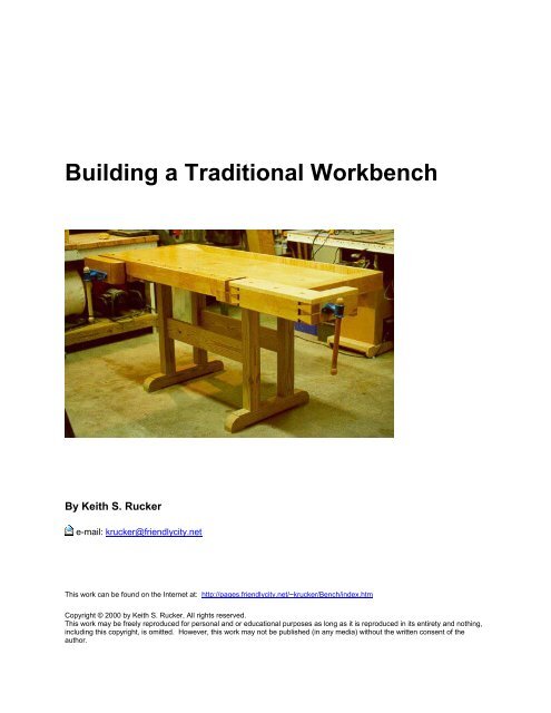
<strong>Building</strong> a <strong>Traditional</strong> <strong>Workbench</strong><br />
By Keith S. Rucker<br />
e-mail: krucker@friendlycity.net<br />
This work can be found on the Internet at: http://pages.friendlycity.net/~krucker/Bench/index.htm<br />
Copyright © 2000 by Keith S. Rucker, All rights reserved.<br />
This work may be freely reproduced for personal and or educational purposes as long as it is reproduced in its entirety and nothing,<br />
including this copyright, is omitted. However, this work may not be published (in any media) without the written consent of the<br />
author.
Table of Contents<br />
Table of Contents..........................................................................................................................................2<br />
Introduction ...................................................................................................................................................3<br />
The Design....................................................................................................................................................4<br />
The Top Design ........................................................................................................................................5<br />
Bill of Materials - Top ................................................................................................................................6<br />
The Base Design...........................................................................................................................................7<br />
The Lumber...................................................................................................................................................8<br />
Milling the Lumber.........................................................................................................................................9<br />
The Top Slab...............................................................................................................................................11<br />
The Dog-Hole Back.....................................................................................................................................12<br />
Mathematical Calculations:.....................................................................................................................14<br />
Making the Dog-Hole Strip..........................................................................................................................16<br />
Making the Dog-Holes ............................................................................................................................17<br />
Cutting the Notch ....................................................................................................................................19<br />
Cutting the Dovetail Pin ..........................................................................................................................19<br />
Gluing the Dog-Hole Strip to the Top .....................................................................................................20<br />
The Dog Hole Slot Cover........................................................................................................................21<br />
The End Caps .............................................................................................................................................22<br />
The Left End-Cap ...................................................................................................................................22<br />
The Right End Cap .................................................................................................................................23<br />
Mounting the End Caps ..........................................................................................................................24<br />
The Tool Till ................................................................................................................................................25<br />
The Tool Till Apron .................................................................................................................................25<br />
Tool Till Bottom.......................................................................................................................................26<br />
The Ramps .............................................................................................................................................27<br />
The Bottom Spacers ...................................................................................................................................28<br />
The Front Vise.............................................................................................................................................29<br />
Front Vise Spacer Block .........................................................................................................................29<br />
The Front Vise Face Block .....................................................................................................................30<br />
Boring the holes in the Face Block .........................................................................................................30<br />
Boring the holes in the bench .................................................................................................................31<br />
Preparing the Bench Face......................................................................................................................32<br />
Installing the Vise Hardware ...................................................................................................................33<br />
The End Vise...............................................................................................................................................35<br />
The Face Piece.......................................................................................................................................35<br />
The Front Jaw.........................................................................................................................................36<br />
The Rear Jaw..........................................................................................................................................38<br />
The Back Runner....................................................................................................................................38<br />
Assembling the End Vise........................................................................................................................38<br />
Fitting it up ..............................................................................................................................................39<br />
The Dog-Hole Cover...............................................................................................................................41<br />
The Guide Block .....................................................................................................................................42<br />
The Bench Runner..................................................................................................................................44<br />
The Front Guide Block............................................................................................................................44<br />
Mounting the Top Caps ..........................................................................................................................47<br />
The Base.....................................................................................................................................................51<br />
Flattening the Top .......................................................................................................................................55<br />
Finishing the Top.........................................................................................................................................56<br />
Details .........................................................................................................................................................57<br />
2
Introduction<br />
If you are going to use hand tools in your woodworking, perhaps the most important tool to have<br />
is not the tools themselves but a good bench to do your work on. When I first started to set up<br />
my shop, I had only been out of school for a little over a year, been married a little less than a<br />
year and had just bought a new home. To help spell my situation out, we were poor. Even<br />
though the finances were not the best in the world, I began to accumulate a few basic tools and<br />
began making some of the much needed furniture in my new home. My first workbench was<br />
pretty simple. When we first moved into our new home, the previous owners had left behind a<br />
crudely made puppet stage, which was actually just several 2x4's screwed together and painted<br />
white. Having no need for a puppet stage in my new "shop" (the two car garage on the front of<br />
my house), I disassembled the puppet stage and reassembled the lumber into the frame of a<br />
bench. Nothing fancy here mind you, I just made a basic frame and put it all together with<br />
screws. The top was made from some scrap 2x6's that were in the burn pile of a new house<br />
that was being built down the street from mine (I did ask the contractor before taking them).<br />
The 2x6's were again screwed down top and presto, I had a bench. A couple of scrap pieces of<br />
plywood made a shelf underneath to stack junk on. A couple of years later, a front vise was<br />
bought and added to the bench.<br />
It was not a pretty bench and it was not really a great bench, but it was the only bench I had. As<br />
my woodworking improved and I started using more and more hand tools, I started to realize<br />
that my thrown together bench was not good enough. Planing was particularly a pain. First,<br />
there was no good way to hold a board while planing. I screwed a couple of stops on the end of<br />
the bench for boards to hold against while planing but there was nothing on the other side to<br />
hold it tight. And, when I was planing, the whole bench racked back and forth resulting in much<br />
wasted energy. The more work I did on this bench the more I realized I needed a new one.<br />
Shortly before my daughter was born (July 1997), I ordered a copy of "The <strong>Workbench</strong> Book" by<br />
Scott Landis. The book arrived just a few days before my daughter did so as I was spending a<br />
lot of time in the hospital waiting to go home with my new little bundle of joy, I spent many an<br />
hour reading my new book (Hannah, my newborn daughter, spent most of this time sleeping<br />
anyway so I had to do something to keep my busy). I must have read that entire book cover to<br />
cover at least twice before going home.<br />
I spent the next three years thinking about my bench and saving what I could so that I could<br />
build one right. After three years of planning, I finally came up with a bench I think I will like.<br />
During that time, I had the opportunity to actually do work on several different types of benches<br />
to see what I liked and didn't like. The result of all of my pondering on the subject was to build a<br />
pretty traditional bench. The following collection of pages is a continuing saga of the step by<br />
stop process I went though to get it done. As I go along, I will discuss what I have learned along<br />
the way so that if you ever decide to build a bench, hopefully you can learn from my mistakes.<br />
3
The Design<br />
After many years of using a totally inadequate bench for hand tools, I finally decided that the<br />
time had come to build a "real" bench. After no telling how many hours of thinking and<br />
sketching, I finally decided on a pretty traditional design. My bench, will basically be pretty close<br />
in design to the Frank Klausz bench that has been well documented in both "The <strong>Workbench</strong><br />
Book" by Scott Landis as well as in Fine Woodworking issue 53 (July/August 1985).<br />
The main difference between my bench and Franks is the front vise. Everything I have ever<br />
read that Frank has written about his bench as well as what he told me while personally talking<br />
with him about it at a weekend workshop, Frank is adamant that the front vise should be of the<br />
"Dog-Leg" style. While it may work great for Frank, I just do not like that kind of vise. I have<br />
had the opportunity to work on one for a while and it just did not suite my work habits. Perhaps<br />
that greatest thing I do not like about the Dog-Leg vise is that it sticks out of the front of the<br />
bench, always getting in the way. It is also weaker by design. I decided instead to go with a<br />
plain front vise, where the front of the bench actually serves as the back of the vise. The only<br />
other differences in my bench and Franks is the dimensions. The only reason I changed them<br />
was to better fit my shop. While I would love to have a bench that is 7' or 8' long, 6' was the<br />
maximum length that would work in my space. I also made my bench a little wider than Frank's,<br />
about three inches wider - not sure if this is good or bad, only time will tell.<br />
4
The Top Design<br />
Here is the plan for the Bench Top. Also below is a copy of the bill of materials for the<br />
workbench top. Again, this bill of materials is a bit rough right now but final dimensions should<br />
not change much.<br />
5
Bill of Materials - Top<br />
Top<br />
Part Name Qty Thickness Width Length<br />
A Dog-Hole Strip 1 2 5/8 4 51<br />
B Dog-Hole Back 1 2 1/2 2 3/4 51<br />
C Top Slab 3 2 1/2 5 3/4 66<br />
D Dog-Hole Slot Cover 1 1 1 1/2 51<br />
E Apron 1 1 4 69<br />
F Left Endcap 1 3 4 30 5/8<br />
G Right Endcap 1 3 4 28<br />
H Tray Bottom 1 1/2 8 1/2 66<br />
I Ramps 2 1/2 7 1/4 8<br />
J Left Spacer 1 1 1/2 2 3/4 25 1/8<br />
K Right Spacer 1 1 1/4 2 3/4 26 1/2<br />
L Front Guide Block 1 3 3 22 1/4<br />
M Guide Block 1 2 1/4 3 1/4 18<br />
O Front Vise 1 2 5/8 5 17 1/4<br />
P Vise Spacer Block 1 1 1/2 2 1/2 17 1/4<br />
Tail Vise<br />
R Rear Jaw 1 3 3/8 4 13 1/2<br />
S Front Jaw 1 3 3/8 4 13 1/2<br />
T Back Runner 1 1 1/2 1 1/2 23<br />
U Face Piece 1 2 5/8 4 23<br />
V Runner 1 1 1 19<br />
W Bench Runner 1 1 1/2 1 1/2 25<br />
X Front Top Cap 1 1 5 3/8 23<br />
Y End Top Cap 1 1 3 3/8 13 1/2<br />
6
The Base Design<br />
Here is the basic plan for the bench base as well as the Bill of Materials. I built my base out of<br />
Southern Yellow Pine simply due economics. It would be better to build the base out of<br />
hardwood. You can easily get by with lumber that has knots in it for the base as long it does not<br />
have any structural defects.<br />
Drawing<br />
Base<br />
Part Name Qty Thickness Width Length<br />
A Foot 2 2 3/4 4 27<br />
B Top 2 2 3/4 3 27<br />
C Uprights 4 2 3/4 3 1/2 30<br />
D Front Tenons 2 1 1/2 5 34<br />
7
The Lumber<br />
The first step in making my bench was to obtain the lumber for it. This in itself was no easy<br />
matter. <strong>Workbench</strong>es are traditionally made from either beech or hard maple. While this is all<br />
good and well, neither of the two species grow in large enough quantities in my area (South<br />
Georgia) to be found at local sawmills or lumber yards. I tried just about every lumber source I<br />
knew of but hardly any of them carried hard maple in thickness greater than 8/4 and none<br />
carried beach. For most of my top, I needed thickness at least 16/4. I did find one supplier that<br />
had some 16/4 but it was so expensive I would need to take out a second mortgage on my<br />
house to pay for it.<br />
I next considered alternative materials for my top. One lumber species that first came to mind<br />
was Longleaf Pine (Southern Yellow Pine). This is the prominent tree species native to my area<br />
and was probably what local craftsman would have made their benches out of. I tossed and<br />
turned on this topic but finally decided to go with hard maple. Southern Yellow Pine would have<br />
worked just fine but heck, most people only build one bench in a lifetime and I wanted to go all<br />
out. Due to the price, I also decided to get my hard maple somewhere besides the South East.<br />
It was suggested to me from the OldTools list to give Paul Taran a try at MapleLeaf<br />
Hardwoods. I could not have made a better choice. Paul went out of his way to get just exactly<br />
what I needed. He even went so far as to ask for a copy of my Bill of Materials so he could<br />
better select boards for me since I could not do it myself. And the kicker was that even with the<br />
added expense of having the lumber trucked down from PA, it was still considerably cheaper<br />
than what I would have paid for it in Atlanta, not counting the 400 mile round trip to haul it from<br />
Atlanta myself. I placed my order and about a week later my bench lumber arrived. Now, I was<br />
in business!<br />
The lumber before any milling<br />
8
Milling the Lumber<br />
The next step was to start milling my lumber to the proper dimensions. I begun my bench by<br />
making the top slab. The slab consisted of two boards, 2 1/2 inches thick, that when glued<br />
together would be 17" wide. Now, the main reason I am building this bench is to use hand tools<br />
on. I love old hand tools, both their beauty as well as the superior job they can do when<br />
properly used. As much as I love these old tools, I also believe that their is a place in the shop<br />
for power tools, particularly when doing the rough milling work in a project. So, if you are one<br />
of those who can't stand power tools (or hand tools for that matter), I will try to discuss<br />
alternative methods of getting the job done as I go.<br />
The lumber I received was rough cut lumber. The boards were great but they did have some<br />
slight cupping and twist to them. The first step in any project is to get a squared up piece of<br />
stock, which first means getting one side of the lumber truly flat. The traditional way of<br />
accomplishing this task is to use a Scrub Plane (like the Stanley #40) to remove wood quickly<br />
and get a rough flat surface. To determine if the face it truly flat, one would use winding sticks,<br />
two long boards placed across the face that when eyed down from the end, any twisting is<br />
easily detected.<br />
While the scrub plane would have worked just fine, I decided to go with the more modern<br />
approach. Rough milling is one place that I feel that power tools are a better option since you<br />
can get the same job done more quickly and with a lot less effort. And since the milling process<br />
usually does not leave the final surface on your lumber, you cannot really tell if the milling was<br />
done by hand or not.<br />
Because of the widths I was working with, getting that flat face to start working with was a<br />
challenge. Usually the standard approach to taking cupping and twist out of a board before<br />
planning is to run a face across the jointer. While this is all good and well, my power jointer is<br />
only 6" wide but the boards I was working with were a little over 10" wide. I finally decided that<br />
the best option was to send the boards through my planner. To take care of the cupping and<br />
twist that would have come out the other side of the planner the same way they went in, I<br />
needed a flat side on the board to work with. Instead of actually milling one side of the board<br />
flat, I simply nailed a board that I knew was flat on one side of my stock and then using small<br />
wedges to firm up the rough board. In my case, I used a piece of 1x12 pine that I checked for<br />
flatness, but a better option would have been a piece of 3/4" plywood. The result was a flat<br />
reference side on my board. I used Winding Sticks to make sure the flat board stayed flat as I<br />
was driving the wedges to tighten up the cup and twist. Once I was sure the bottom board was<br />
flat, I ran it all through the planner until the top of the rough board cleaned up. I then checked<br />
the top of the board with winding sticks again, and sure enough, it was flat. The toughest part of<br />
the whole process was man-handling those huge timbers by myself.<br />
9
The Winding Sticks on the flat top of my board after planning. Notice the "flat" board which is nailed onto<br />
the bottom with wedges to keep it from rocking.<br />
Once I had the one flat side, I then used the jointer to get a square edge on the board. Next, I<br />
ripped the board to a little wider than it's final width on the table saw. I had a little trouble with<br />
the ripping part as my Craftsman table saw just did not have enough horsepower to handle the<br />
3" thick hard maple. I had to feed the lumber extremely slow and even then, I was running back<br />
and forth to the electrical panel to reset tripped circuit breakers.<br />
With the two square sides on my boards, I then ran the boards through the planner with the flat<br />
sides down to square up the other two sides and to get the board to it's proper dimensions.<br />
10
The Top Slab<br />
Once I had some squared up timbers for the top, I next got the two main pieces for the top slab<br />
ready to glue up. The top slab on my bench is 2 1/2" thick by 17" wide. Because I had 16/4<br />
lumber (3" thick) that was about 10" wide, I decided to just edge glue two pieces together to<br />
form the slab. The ideal situation would be to have the slab made from quartersawn lumber to<br />
help keep down wood movement. However, since I was not able to find any quartersawn<br />
lumber in these dimensions, I just opted to go with the flatsawn faces. Another alternative<br />
would to have been to rip several boards, turned them with the quarter sawn side up and glued<br />
it all together. Using this method, 8/4 lumber could have been used instead of 16/4, perhaps<br />
saving a little money as well.<br />
To help align the boards together, I cut a 1/2" grove on the two mating surfaces and then used<br />
1/2" thick plywood splines for alignment. To cut the groove, I had several options. The hand<br />
tool method would be to use a plow plane. I seriously considered using my Stanley 45 but it<br />
was already too hot in the shop and getting late (I was dead tired). Another option would be to<br />
make the slot on the table saw using a dado head. While this would have perhaps been the<br />
easiest method, I decided against it for one major reason - if there had been any bowing in the<br />
board, the resulting groove may not have been perfectly parallel to the top of the board. The<br />
main reason I was using a spline in the first place was to help align the boards together to the<br />
boards would be flush on the top with one another. So, I opted to use the router. By using a<br />
fence on the router, the groove was always the same distance from the top and if there was any<br />
bowing, the boards should have come out at least flush on the top.<br />
Once the groove was made, I then made a spline out of 1/2 plywood. I cut a slight chamfer on<br />
both sides of the groove as well as on the spline with a block plane to help the spline fit into the<br />
groove. I spread a little glue on the spline and tapped it in. I then spread some glue on the<br />
mating boards and clamped it all together. You can never have to many clamps!<br />
Top slab being glued up. Notice the plywood spline to help in alignment.<br />
Once the glue had dried, I cut the top to length being extremely careful to make square cuts. I<br />
made my square cuts on the table saw using a cutoff sled.<br />
11
The Dog-Hole Back<br />
To close the back of the dog-hole strip, there is another piece of the top called the Dog-Hole<br />
Back. This piece also serves another function in that there is a slot milled into it to hold a<br />
hardwood stop. The hardwood stop is simply a 1/4" thick by 2" wide strip of hardwood that can<br />
be extended up from the bench top to serve as a stop. It comes in handy for several jobs on the<br />
bench including planning or anytime you need a stop to hold a board in place without clamping<br />
it.<br />
The Dog-Hole back is a piece of maple 2 1/2" thick (same as the top slab) and 2 3/4" wide. It<br />
mates up to the slab but does not go all of the way to the end of the end vise. It is necessary to<br />
leave a notch on the end for the end-vise to fit into.<br />
The most difficult part of milling the Dog-Hole Back is cutting the slot for the Hardwood Stop. I<br />
considered several ways to make this slot but the best way I came up with was on the table<br />
saw. The slot is 1/4" wide so you would at first think of using the dado head on the table saw to<br />
cut it. My dado head, however, is only a 6" dado head and would not stick up through the table<br />
saw far enough to cut to the necessary 2" depth. So, I just decided to use a regular table saw<br />
blade, moving the stock over a little at a time until the slot was 1/4" thick.<br />
The other trick to the Hardwood Stop is that like the dog-holes, it is at a 88° angle. To<br />
accommodate this angle, I needed to cut the board at a angle across the table saw blade. I<br />
could have used my miter gage to do this however, I did not feel that the miter gauge would give<br />
me enough support for such a large timber.<br />
Some time back, I made a cross-cut sled for my table saw. If you have not ever made one, now<br />
is the time - it is one of the most handy accessories in my shop. Now the crosscut sled cuts at a<br />
perfect 90° angle. To make the 88° angle, I simple shimmed one side of the back fence and<br />
clamped the board in at the proper angle.<br />
After making the cut, here is the resulting slot:<br />
12
Once the slot was cut, the Dog-Hole Back was cut to its proper length and prepared to glue to<br />
the top slab. As with the two pieces on the top slab, I milled a 1/2" groove and installed a 1/2"<br />
plywood spline to help in alignment. Here is a picture of the grooves before glue up:<br />
13
Mathematical Calculations:<br />
To determine the size of the shim, I used some Trigonometry (and you always told your math<br />
teacher that you would NEVER need that stuff in the real world). Here is what I knew: I knew<br />
that the angle I needed on one side was 2° (90-88). I also knew the length from one end of my<br />
sled to the other end. What I needed to know was how far to shim the other end. Now, if you<br />
think about it, what we have is a right triangle where we know the angles of the corners (2° , and<br />
90 degrees) and the length of the bottom leg.<br />
To solve for the side, we use the following equation:<br />
For the angle pictured in the figure, we see that<br />
In our example, we have the following:<br />
So:<br />
Tan 2 = X/29.5<br />
or to simplify:<br />
(Tan 2)*29.5<br />
Which equals 1.03". I just rounded it to 1" to shim the end. Here is a picture of the board set up<br />
to cut the angle:<br />
14
The board set up to cut the slot<br />
15
Making the Dog-Hole Strip<br />
One of the most important features of a good bench, in my opinion, is the dog-holes that allow<br />
you to clamp a piece of wood to the top of the bench. The dog-holes are square holes in the top<br />
of the bench that allow you to slip a square "Dog" into the hole. The Dog's can be lifted up so<br />
that they protrude from the top enough to clamp a board to the top. Two dogs are usually used,<br />
one that stays stationary and another in the end vise that when the end vice is tightened,<br />
clamping pressure is applied to between the dogs.<br />
Some people use round dogs instead of square. The main reason that they do is because<br />
round holes are easy to make - just drill some holes in the top. I like square dogs for several<br />
reasons. First, a square dog will not rotate in its hole, twisting loose when you least need it to.<br />
And second, most round dog holes are drilled at a 90 degree angle to the top which can mean<br />
they can slip up under a load.<br />
Square dogs, on the other hand cannot twist. Also, square dogs are cut at a slight angle (about<br />
88° instead of 90°). The result of this slight angle is that when clamping pressure is applied to<br />
the dog, it actually presses the board down toward the bench.<br />
The secret to cutting square dog holes is to cut them into the side of a board (the dog-hole strip)<br />
and then face glue a second board to the side to close the square hole.<br />
16
Making the Dog-Holes<br />
There are three methods that I have come up with to cut the dog-holes into the dog-hole strip.<br />
First, you could use hand tools. To do it this way, you could use a back saw to cut the two sides<br />
of the slot and then use a chisel to remove the waste. Second, you could use a dado head on a<br />
radial arm saw. Of course the saw would have to be set to 88° rather than 90°. Alternatively,<br />
you could use a dado head in your table saw and slide the dog-hole strip over the top with the<br />
miter gage or some other holding jig set to the proper angle. And third, you could use a router to<br />
remove the waste. With the router, method, a simple jig could be used get the desired angle<br />
and shape.<br />
One thing to remember when making a dog-hole slot is that the slot is not a simple grove. In<br />
order for the dog to be able to slide all the way down into the bench so that it will be out of the<br />
way or to have only a portion of the dog sticking up from the bench, you have to remove an<br />
extra area to the front of the dog-hole slot. Once the slot is cut, the extra area could easily be<br />
chopped out with a chisel.<br />
After studying the several possible methods of cutting the dog-hole slot, I finally decided to use<br />
the router method. With the router, I could make a jig that would cut a uniform angle as well as<br />
remove the extra area in the front of the dog-hole all at the same time. To use the jig, you will<br />
need a guide bushing for your router which is nothing but a collar that the router bit fit through<br />
on the under side of the router. You then simply slide the guide bushing up against the side of<br />
the template and remove all of the waste in between. I made my template out of 3/4" plywood,<br />
cutting the piece in half at 88° and then removing the extra area for the dog-hole to slide into. A<br />
wooden fence was screwed to the bottom of the jig to hold the two pieces at the proper distance<br />
apart as well as to hold the jig squarely to the top of the dog hole strip.<br />
I set the depth of my router bit to the proper depth of the slot and then clamped the jig onto the<br />
dog-hole strip in the proper location. The router then made quick work or waste removal.<br />
17
Jig clamped to strip ready to be routed.<br />
One word of caution. Before cutting any dog-holes, be sure to think things through completely.<br />
One thing to remember is that around the front vise, you may have to alter the dog-hole spacing<br />
in order for the dog-holes to avoid the hardware in the vise. Lay everything out and think things<br />
through. You can't put that wood back in once it is gone.<br />
The finished dog-holes.<br />
18
Cutting the Notch<br />
On the tail vise end of the dog-hole strip, it is necessary to cut a notch on the bottom to allow a<br />
board to fit into. There are several ways to cut the notch, one would be with hand tools where<br />
you could use a back saw to cut out the waste. I however, chose to use the table saw to help<br />
assure that I got a perfectly straight and square cut. I did this operation using my cross cut sled,<br />
raising the height of the blade to just shallow of the depth of the cut. I made the shoulder cut<br />
first, being extremely careful to make it right on the line. Once the first cut was made, I then just<br />
nibbled out the rest of the waste by moving the board over a little at a time until the waste was<br />
gone. To clean up the bottom of the cut (which was jagged), I first used a wide chisel and then<br />
used a shoulder plane to get a smooth bottom.<br />
Cutting the Dovetail Pin<br />
On the other end of the dog-hole strip (the front vise end), there is a large dovetail which helps<br />
hold the end-cap in place. As with making conventional dovetails, I chose to cut the pins first,<br />
which in this case is the part on the dog-hole strip. Now, when it comes to dovetails, I am pretty<br />
much a strong believer in doing them by hand - I own no dovetail jigs in my shop. Once I did<br />
the lay out on the dovetail pin however, I quickly noticed one big problem with doing this by<br />
hand - my dovetail saw, and even my only back saw, did not have a blade deep enough to<br />
make the huge dovetail pin. I could have spent some time to try to find a larger saw to buy but<br />
down here in South Georgia, I had about as much of a chance in finding a good user back saw<br />
as we do in seeing snow in the winter (maybe once ever decade or so!). So, I went the next<br />
best choice which was my band saw. This is the way that Frank Klausz cut his dovetails on his<br />
bench so I did not feel to bad in doing so.<br />
I decided on a angle on my dovetail of about 10° just simply because that is what Frank did on<br />
his. I used my bevel square to mark the angle on the wood and then adjusted the table on my<br />
band saw to match the angel again using my bevel square. I again quickly noticed a small<br />
problem - my band saw table only tilted one way and in order to make the two angles of the<br />
dovetail, I would have to tilt it both ways. I scratched my head and decided to just make a tilt<br />
table out of wood that would do the trick. I could simply turn it around to make the opposite cut.<br />
The angel table, shown in the picture below, only took about 10 minuets to make out of come<br />
scrap plywood and a scrap 2x4. I put the widest blade I had on the band saw (1/2") and made<br />
the cuts. I then switched to 1/4" blade and cut the majority of the waste out instead of even<br />
trying to chisel it all (3" thick would have taken forever). To remove the waste in the corners of<br />
the dovetail, I used a coping saw. A chisel was then used to clean up the bottom, cutting it right<br />
to the line. My dog-hole strip was now complete and ready for gluing.<br />
19
Cutting the dovetail pins on the band saw.<br />
Gluing the Dog-Hole Strip to the Top<br />
Once the dog-hole strip was completed, it was ready to glue to the top. The dog-hole back had<br />
previously been glued to the top. Since I could not use a plywood strip to help align the doghole<br />
strip (the slot and spline would have interfered with the dog-holes), I decided to use a few<br />
biscuits to help in alignment. I did not feel that the biscuits would give much if any extra<br />
strength to the glue joint, but they would come in handy in helping to align the tops flush with<br />
one another. After cutting the biscuits, I carefully lined up the ends to be sure they were flush<br />
and glued and clamped the dog-hole strip in place.<br />
The Dog-Hole Strip glued into place.<br />
20
The Dog-Hole Strip Dovetail.<br />
The Dog Hole Slot Cover<br />
Because the front Dog Hole Strip is thicker than the rest of the bench top, the dog hole slots are<br />
not covered on the back of the dog hole strip on the bottom of the bench. To fix this, a 1" x 1"<br />
strip is cut and glued to the back of the dog hole strip.<br />
The Dog Hole Slot Cover being glued into place.<br />
21
The End Caps<br />
The next step on the bench top is to put the end-caps into place. There are two end-caps on<br />
the bench, one on the front-vise end and one on the end-vise end. Both are different in design<br />
and will be covered separately in discussion.<br />
Some people consider end-caps to be a weak design point in the traditional woodworkers<br />
bench. Because the end-cap is running perpendicular in grain to the rest of the top, there is<br />
concern that as the top moves with changes in temperature and humidity, the end-caps could<br />
actually force a failure in the top. While this is a legitimate concern, this style of bench has been<br />
made for centuries and most hold up well as long as some care is taken in design as the bench<br />
is made. As long as you do not glue then entire length of the end-cap to the top, you are in<br />
essence allowing the top to move without trying to hold it down with glue. As with other parts of<br />
the top, plywood splines are used on the end-caps, but without glue so they can move with<br />
seasonal dimensional changes without causing a failure.<br />
The Left End-Cap<br />
The first step in making the end-caps is to mill the lumber to dimension and square. After rough<br />
milling, you are ready to make the special features of the end-caps.<br />
The main design feature of the left end-cap (the front vise end of the bench), is the large<br />
dovetail that will fit into the pins of the dog-hole strip. The tail was cut out on the band saw,<br />
being sure to leave the line marked from the pins. After the waste was removed, I then cleaned<br />
up the tail and cut it to fit using sharp chisels. After a couple of test fits and removing a little<br />
more waste, it fit satisfactory.<br />
The next step was to cut the groove for the plywood spline as in the other parts of the top. Care<br />
was taken not to cut the slot where it would show in the tool till. A plywood spline was inserted<br />
into the groove and glue was spread ONLY on the dovetail end of the end-cap and it was<br />
clamped into place.<br />
And Finally, the half blind dovetail pins were cut on the back of the end-cap to fit the tool till tray<br />
back. These pins were cut using traditional methods of first laying out the pins and then sawing<br />
as much waste as possible with a dovetail saw. The waste was then removed by chopping it<br />
out with a chisel.<br />
22
The Right End Cap<br />
The right end cap is totally different from the one on the left. The main feature of the left end<br />
cap is the hole bored through the front end to receive the nut for the end vise. In order to bore<br />
the correct size hole, you must first obtain your vise screw and measure the diameter that will<br />
be necessary for your hardware. Once the correct size is determined, bore a hole just large<br />
enough that the nut will slip inside. On mine, I first bored the larger hole for the nut to the<br />
correct depth and then finished the hole by boring a smaller hole just slightly larger in diameter<br />
than the screw diameter. The result was a stepped hole.<br />
The mounted right end cap.<br />
It is also necessary to cut away a notch of the front of the end cap to allow the 1" thick tail vise<br />
cap to slide over.<br />
As with the left end cap, dovetail pins were cut on the back side to accommodate the tool till<br />
back.<br />
The half blind dovetail pins being cut on the end caps.<br />
23
Mounting the End Caps<br />
Since spreading glue over the entire face of the end cap would result in a weak joint against the<br />
end grain of the top, not to mention the chance of a joint failure as the top expands and<br />
contracts, a bolt was used to help hold the end cap in place. I used a drill to bore a 3/8" hole<br />
into the end caps, deep enough to go well into the top. In my case, I used 7" long bolts. Once<br />
the holes were drilled, I then used the router to cut a slot on the bottom of the bench that would<br />
allow me access to the end of the hole.<br />
Notice the slot cut into the bottom of the bench to allow the nut to fit into. Also notice the screw nut for the<br />
tail vise.<br />
A small amount of glue was applied to the front of the end caps to be sure that even as the top<br />
expanded and contracted that the front of the end cap would always remain flush with the front<br />
of the bench. I then inserted the bolt into the hole and put a washer and nut into the slot on the<br />
bottom. A couple of turns with a pair of wrenches, the end cap was clamped into place.<br />
24
The Tool Till<br />
The Tool Till on a bench is a very handy accessory. Many people choose to not put a tool till on<br />
their bench, opting for more bench top space instead. The way I see it, the tool till really does<br />
not give you any less real estate on your top at all. If you are working on a large piece, it will still<br />
rest on the till back board resulting in no lost space. The advantage of the tool till is that any<br />
tools on the bench can be kept in the till when moving a large piece on the bench top. As a<br />
result, the tools do not fall to the floor, possibly damaging them and they are still within arms<br />
reach when needed. Of course, the best reason to have a tool till is that it just would not be a<br />
traditional workbench if it did not have one.<br />
The Tool Till Apron<br />
The tool till is a relatively easy step in the building of the bench. Its main piece is the back<br />
apron, which is held in place by half blind dovetails cut into the back of the end caps. On my<br />
bench, I chose to dress things up a bit by using a piece of curly maple for the back apron.<br />
When I ordered the lumber for my bench, I also ordered some extra lumber for future use<br />
including some nice figured stock. Since I had it on my lumber rack, I decided this would be an<br />
appropriate use for it.<br />
To make the back apron, first mill the lumber to the appropriate dimensions. Then, cut the tails<br />
for the dovetails. In my case, I almost always cut the pins first when making dovetails. In this<br />
case, the pins were cut into the end caps before mounting them to the bench. I temporarily<br />
clamped the back apron into where it would eventually fit and used a pencil to mark the tails. I<br />
then unclamped the back apron from the bench and cut the tails of the dovetail using traditional<br />
methods, cut the waste with my dovetail saw and then chop out the waste.<br />
Then next step in making the back apron was to cut a dado for the tool till bottom to fit into. This<br />
could be accomplished with a plow plane, a power router or on the table saw with a dado head.<br />
Since the dovetail tails are going into half blind dovetail pins, you can cut the groove all the way<br />
through the ends - they will not show from the ends after glue-up. The tool till bottom is 1/2"<br />
thick so make your dado 1/2" thick and around 1/4" deep. Be sure to cut the dado where the<br />
installed bottom will be flush with the bottom of the bench.<br />
Once the back apron is finished, spread some glue and clamp it into place.<br />
25
The dovetails on the back apron and back of the end caps.<br />
Tool Till Bottom<br />
The next step is to make the tool till bottom. On Frank's bench, he used 1/2" plywood for his<br />
bottom. While I can see the advantage of using plywood for the bottom (it will not contract and<br />
expand like solid wood), I did not happen to have a sheet of nice 1/2" plywood in my shop (I did<br />
have some rough construction grade stuff but that would never work on my bench) and the only<br />
supplier was about three hours away. So, I decided to just glue up some maple boards to make<br />
the bottom instead. Once I had the proper width needed, I planed the board down until it would<br />
fit into the dado I had cut into the back apron. I then turned the bench upside down, spread a<br />
small amount of glue into the dado and clamped the bottom into place.<br />
Once the glue had dried, I then prepared to screw the tool till bottom down to the bottom of the<br />
bench. Instead of just drilling the bottom right down, I instead first drilled pilot holes for all of my<br />
screws. I then took a drill and made the hole in the 1/2" thick tool till bottom into slots by moving<br />
the drill back and forth. By making slots, I at least in theory gave the tool till bottom the ability to<br />
slip a little as the bench top moved in width with the changing of seasons. I then screwed the<br />
tool till bottom into place.<br />
The bottom of the bench after the tool till tray was installed.<br />
26
The Ramps<br />
The last step in completing the tool till is to put the ramps on each end. The purpose of the<br />
ramps is to help in brushing shavings out of the till. Without the ramps, it would be difficult to<br />
remove the waste, however, with the ramps, a brush can easily be used to clean the till by<br />
brushing up the ramps.<br />
Frank made his ramps out of plywood. Again, I did not have any maple plywood to match the<br />
bench so I used solid wood. Actually, mine were made from some scrap strips that I had laying<br />
around the shop that I glued up to get a wide enough board. I then planed the boards to about<br />
1/2" thick (thickness is not really an issue on this part) and cut them to widths that fit the inside<br />
of tool tray. I then determined the correct angle that needed to be cut on each end of the ramp<br />
and adjusted my table saw blade angle to that angle and then cut the two angles on the board.<br />
The final step was to glue the ramps into place.<br />
Clamping the ramp into place as it is glued.<br />
27
The Bottom Spacers<br />
Now that the top is getting pretty well along, it is time to put the bottom spacers on the bottom of<br />
the bench top. The purpose of the bottom spacers is to give the bench top something to rest on<br />
the base. The bottom spacers are pretty simple to make, just a simple spacer that is screwed to<br />
the bottom of the bench. Before screwing the bottom spacers into place, be sure to have both<br />
the front and end vises laid out so you know were all of your hardware will go and the spacers<br />
will not be in the way. Cut the spacers length about 1/4" shorter then the width of the top<br />
bottom in which they will fit. This will allow for any wood movement in the top. A notch will have<br />
to be cut out on the back side where the spacer will fit over the tool till bottom.<br />
Once the spacers are made, attach them to the bottom of the bench top with two large screws.<br />
Do not use any glue since you would be gluing the spacers across the grain of the top. As the<br />
top moves, their would be a failure somewhere on the bench top resulting in split wood.<br />
A bottom spacer mounted.<br />
28
The Front Vise<br />
Since I have uploaded this site, several people have e-mailed me wanting more information on<br />
where to purchase vise hardware.<br />
Vice hardware is readily available from most major suppliers of woodworking supplies. If I<br />
remember correctly, I purchased my hardware from Woodworker Supply. They don't have a<br />
web site but do have one of the best catalogs in the industry. If you do not already receive this<br />
catalog, you need it. You can request a catalog by calling 1-800-645-9292. The main reason I<br />
purchased my hardware from there was the price. It is quality stuff but I did not like the fact that<br />
it was painted blue - if I had it to do over again, would have rather had a more traditional black<br />
even if it cost a few dollars more.<br />
Other suppliers that I know have the hardware are:<br />
Woodcraft: http://www.woodcraft.com/<br />
You can do a search for "vise" and then look at their Front Vise Hardware for the Front Vise and<br />
their Bench Screws for the end vise.<br />
Highland Hardware: http://www.highland-hardware.com/<br />
This is by no means the only suppliers of vise hardware but should give you a good start.<br />
Front Vise Spacer Block<br />
Because of the height of the vise carriage, it is necessary to put a spacer on the front of the<br />
bench to allow the guide rods and screw to have support as they go through the front of the<br />
bench. The spacer block should be the same length that the length of your front vice will be.<br />
The actual height will depend on the vise carriage you have purchased so dimensions may<br />
need to be adjusted from what I have in my diagram. You will also need to drill clearance holes<br />
for the dogs to pass through. The spacing of your holes will again depend on the dog hole<br />
spacing on your bench.<br />
29
Once you have the spacer block made, attach it to the bottom of the dog hole strip by gluing it<br />
and then screwing it into place. Be sure that your screws will not be in a position to interfere<br />
with the guide rods and vise screw holes that will be bored through the spacer block in a later<br />
step.<br />
The Front Vise Spacer Block mounted on my bench<br />
The Front Vise Face Block<br />
The next step is to make the piece of wood that will become the actual front vise. I wanted mine<br />
to be pretty massive, about 3 1/2 inches thick. Now, the thickest lumber I had was the 3" thick<br />
hard maple. To get it a little thicker, I needed to glue a second piece onto one side. I could<br />
have used another piece of hard maple, but to add some contrast to the vise, I instead decided<br />
to glue on a piece of 4/4 walnut to the face. I then used a jointer plane to get a smooth and<br />
perfectly flat face on both the front and back. The finished block was 17 1/4" long, 3 1/2" thick<br />
and 5 1/4" wide.<br />
Boring the holes in the Face Block<br />
Next, I needed to drill the holes in the face block that the vise guide rods and screw would go<br />
though. On my vise hardware, the guide rods were 3/4" in diameter and the screw was 1" in<br />
diameter. To lay out the correct position for the holes, I first marked a center line across the<br />
length of the block and a second line that represented the thickness of the top, measured from<br />
what would become the top of the face block. I then laid the vise carriage onto the vise block,<br />
flush with the line that represented the thickness of the bench and centered on the center line.<br />
A drill bit of the same diameter as the guide rod holes and of the screw holes was slid down into<br />
their respective holes to mark the correct drill locations. The holes were then bored on the drill<br />
press to assure a perfect perpendicular hole. The holes for the guide rods were drilled to the<br />
same size as the guide rods (on mine 3/4") and the screw hole was drilled 1/4" larger than the<br />
screw size to allow for easy turning (1 1/4" hole on my vise).<br />
30
After the holes in the face block were drilled, I took it to the band saw to cut the rounded edge. I<br />
used a woodworking rasp to help remove the saw marks and put the final shaping on the round<br />
over.<br />
Boring the holes in the bench<br />
Next, I needed to drill the guide rod and screw holes through the bench. To help layout the<br />
correct hole position, I used the holes in the vise block as a template. I took the vise block and<br />
clamped it to the bench in the exact position I wanted it end up at. I next used drill bits of the<br />
same size as the holes already drilled into the vise block to mark the center of the holes in the<br />
bench. After marking the correct position, I removed the front vise from the bench and bored<br />
the holes through the bench. These holes all needed to be drilled 1/4" over size to allow both<br />
the guide rods and the vise screw to go through the bench without actually touching the bench.<br />
On my vise, this meant a 1" hole for the guide rods and a 1 1/4" hole again for the vise screw.<br />
Be extremely careful to drill the holes square to the face of the bench.<br />
31
Using drill bits to mark the center of holes on the bench.<br />
The Finished Holes.<br />
Preparing the Bench Face<br />
It is important to remember that once you install the bench hardware, you will not have a chance<br />
to go back and work on the surface of face of the bench or vise block - the guide rods and vise<br />
screw will be in the way. To make sure that both the face of the bench and the vise block are<br />
perfectly flat and meet together without any gaps, I next took a jointer plane (my Stanley #8) and<br />
planed both surfaces until they met together perfectly.<br />
32
Installing the Vise Hardware<br />
Next, I attached the vise hardware to the face block. To help the guide rods slide though the<br />
tight fit of the face block holes, I first rubbed the rods down with a coat of paste wax. I then<br />
inserted the guide rods into the face block holes and using a dead blow hammer, tapped the<br />
hardware all the way down. A couple of screws then secured the hardware to the face block.<br />
The Vise Hardware attached to the Face Block<br />
Next, slide the guide rods and screw through the face of the bench. Then slide the vise carriage<br />
onto the guide rods and slide it up flush to the back of the bench dog hole strip. Tighten the<br />
screw on the vise, being careful to position the face block where you want it to be at<br />
completion. Once you are sure everything is positioned correctly, screw the carriage to the<br />
bench. You may have to remove the face block from the bench and carriage to expose all of<br />
the carriage screw holes.<br />
33
Bottom view of the installed Front Vise.<br />
Top view of the installed Front Vise.<br />
34
The End Vise<br />
Of the entire bench, perhaps the most complicated part to build was the end vise. For me, I<br />
think I was a little frightened to even begin the process. Before beginning this step, I would do<br />
what I did, study everything you can find on how to complete this portion of your bench. I can't<br />
tell you how many times I read the chapter in "The <strong>Workbench</strong> Book" on Frank's bench. I also<br />
spent a fair amount of time sketching out how it would go together and even making drawings in<br />
AutoCAD to help my understanding. I guess the only thing I didn't do was make a mock up first,<br />
and it wouldn't have been a bad idea.<br />
I can say that once I got started on the end vise, it actually went together much better than I had<br />
anticipated. Just take it one step at time and try not to get ahead of yourself.<br />
The Face Piece<br />
The first piece I worked on was the Face Piece.<br />
After working the stock down to its final dimensions, I next made the dog-hole slots. I used the<br />
same procedure to do this as in the dog-hole strip, except that the slots on the face piece are<br />
cut in the opposite direction so that as the vise is tightened, the pressure on the dogs will be<br />
working to your advantage. I used the same router jig as before but to cut the strips at the<br />
opposite direction, I had to turn the jig over and reposition the fence. Also, since there will be a<br />
top cap on the top the face piece, the notch on the front side of the slot did not have to be as<br />
deep as the ones in the dog-hole strip.<br />
Next, I cut the dovetail tails. Remember that the left dovetail will be a half blind dovetail and the<br />
right one will be a through dovetail. For this reason, the depth of the right dovetails needs to be<br />
deeper than those on the left. I used a 10° angle on these dovetails just as elsewhere in the<br />
bench. I made my cuts on the band saw simply because of the depth of cut, which was deeper<br />
than my dovetail saw would cut.<br />
35
Once the waste on the dovetails was removed, I cut the step on the back side of the face piece.<br />
The main reason I did this was to cut down on the amount of waste I would need to remove on<br />
the jaw pieces. Again, I used the band saw to remove this waste.<br />
The Front Jaw<br />
The most complex part to mill on the end vise was the front jaw.<br />
Due to the width of the front and rear jaws (3 3/8") and the maximum width of my lumber (12/4),<br />
I needed to laminate a second piece of lumber to get the width. As with the front vise, I chose to<br />
use a contrasting color of wood for this piece to add some character to the bench - I chose to<br />
use walnut.<br />
Once the stock was milled to final dimensions, I next cut the dovetail half-blind pins. This was<br />
done in pretty traditional methods. First, I cut the slots with a back saw (too deep for my<br />
dovetail saw) and then removed the waste with a chisel.<br />
36
Sawing the half-blind pins<br />
Removing the waste<br />
After cutting the dovetails, I next cut the slots for the two runners. The runner in the middle of<br />
the bench was 1 1/2" by 1 1/2", which was cut on the table saw using the crosscut sled to<br />
assure a square cut. Next, I cut the slot for the back runner. This slot will fit the rear runner with<br />
a finger joint. The last step was to cut the large step on the top of the jaw, which was cut out on<br />
the band saw.<br />
37
The Rear Jaw<br />
The Rear Jaw is similar to the front jaw except that it is not near as complex. The first<br />
step was to cut the dovetail pins. I made the cuts on the band saw using the 10° table jig that I<br />
made in a earlier step. The waste was then removed by chiseling.<br />
On the Rear Jaw, there is only a need to cut a slot for the back runner, which will be finger<br />
jointed to the back just like with the Front Jaw.<br />
The Back Runner<br />
The Back Runner is perhaps the easiest part of the end vise to make. It is simply a 1 1/2"<br />
square strip. At this point, to make sure you cut the finger joints in the correct position, I first put<br />
the rest of the vise together dry and clamped it into position on the bench. I then marked where<br />
the runner should be positioned and marked on it where the slots needed to be cut. I made the<br />
cuts on the band saw and removed the waste with a chisel.<br />
Assembling the End Vise<br />
At this point, I again dry fit everything together, taking care to fine tune all joints to fit together<br />
tightly but smoothly.<br />
All of the parts laid out ready to glue and clamp<br />
38
I next spread some glue and clamped it all together, taking care to be sure everything was<br />
square and tightly clamped into place.<br />
Clamping it all together<br />
Fitting it up<br />
Once the glue was dry, I next did some finishing work to the end vise assembly. First, I worked<br />
on the four corners where the joinery was exposed. I took a low angle block plane to trim the<br />
joints flush and square. Next, I used a jointer plane to get the top of the face piece perfectly flat<br />
for the top caps to fit on top of.<br />
Jointing the top flat<br />
39
Next I took some extra steps to permanently secure the back runner into place. On Frank's<br />
bench, he used a dovetail joint on the back runner instead of a finger joint to assure that it did<br />
not slip. While a dovetail would have made a beautiful joint, I just decided it was not worth all of<br />
the extra worry to make one. A finger joint would be plenty strong and where joints are located,<br />
it is hardly noticeable from a aesthetic consideration. To make sure that the finger joint never<br />
slipped, I pinned it with two wooden dowels on each end.<br />
Pinning the finger joint with dowels<br />
40
The Dog-Hole Cover<br />
The last step in finishing the End Vise assembly was to cover the back of the dog-holes. To do<br />
this, a 1/8" piece of plywood was cut and glued into place.<br />
Clamping the Dog-Hole Cover<br />
And finally, I cut and screwed the front runner to the back of dog-hole cover. The front runner is<br />
a piece of maple 3/4" by 7/8" that runs on top of the end cap.<br />
41
The Guide Block<br />
Now that the End-Vise assembly is complete, we need to get ready to mount it to the bench.<br />
The first step in mounting is to make and attach the Guide Block.<br />
The Guide Block serves several functions. First, it will be the bottom part of the clamping jaw on<br />
the bench side of the End Vise. Second, it supports the bench runner which will help assure<br />
that the vise opens and closes square and without racking. While I show dimensions as to<br />
where the notch for the bench runner was positioned on my bench, you will need to locate the<br />
best place for your bench.<br />
To locate the proper position for the bench runner, clamp the End Vise assembly into place on<br />
the bottom of your bench, taking care to be sure it is exactly where you will want it to be after<br />
construction - make sure it is square.<br />
Next, position the bench runner where it will be mounted and mark the proper position on the<br />
guide block.<br />
42
Marking the position of the bench runner<br />
After marking the position, remove the waste for the notch. Be sure to remove it to a depth that<br />
fits the notch that is already cut in the front jaw of the end vise. I removed the waste on the<br />
table saw using the cross cut sled to assure a square cut. I then cut a relief from the end of the<br />
notch to the back of the guide block on the jointer. The purpose of the relief is to make sure that<br />
the back of the end vise does not come in contact with the guide block when clamping, perhaps<br />
resulting in an un-square closure of the vise.<br />
Next, I took 3/8" by 4" long lag bolts and bolted the guide block to the bench. Take extra care to<br />
be sure the guide block is being bolted down square to the front of the bench! No glue was used<br />
for two reasons, first I did not want to glue it to the bench bottom due to cross grain<br />
construction, which could cause problems as the bench top moved, and second, I did not glue it<br />
in case I ever needed to remove the guide block in the future to make adjustments in the vise as<br />
it wears.<br />
Also notice that I had to cut a hole in the guide block for a dog hole that was located beneath it.<br />
If I had the bench to build over again, I would have located the first dog-hole in the dog-hole<br />
strip behind where the guide block would be mounted. Live and learn...<br />
43
The Bench Runner<br />
I next put the bench runner into both slots and marked the correct position it will be attached on<br />
the end cap. Take special care in finding this position. I clamped the bench runner to the end<br />
cap and slid the vise back and forth several times to make sure that it would slide without<br />
binding and being sure it was square.<br />
The Bench Runner clamped into final position<br />
The Front Guide Block<br />
The next step is to make and mount the front guide block.<br />
The purpose of the Front Guide Block is to simple hold the three runners in place. While there<br />
are dimensions for the location of the three notches for the runners, you will need to carefully<br />
mill them in the correct position for your vise, these dimensions are just roughly where they will<br />
be.<br />
44
Once everything has been milled, clamp the front guide block into position and move the vise<br />
back and forth to be sure it moves smoothly and without binding. If any fine tuning needs to be<br />
done, now is the time to do it.<br />
The next step is to drill a hole in the rear jaw for the bench screw. To locate the position for the<br />
screw, take a 1" dowel rod (or whatever size fits snuggly into the screw nut on your hardware)<br />
and slide it through the screw nut up to the rear jaw. Take a pencil and mark all of the way<br />
around the dowel rod. This mark will determine the center of the hole. On my bench, the screw<br />
had a 1 1/4" outside diameter. To be sure that the bench screw does not rub anywhere on the<br />
hole and to compensate for any error in drilling, I bored a 1 1/2" hole through the rear jaw.<br />
Once you are satisfied with everything, blot the front guide block into place with lag bolts as with<br />
the other guide block. As with the other guide block, do not use any glue so that you can take<br />
the end vise apart in the future for any needed repairs or adjusting. Next screw the bench<br />
screw all of the way into the end vise and mount it in place using large screws.<br />
The Front Guide Block mounted with the bench screw in place<br />
45
The bottom view of the bench will both vises mounted<br />
Top View of vise before top caps are installed<br />
46
Mounting the Top Caps<br />
The final step in completing the end vise is mounting the top caps. The first step was to mill two<br />
pieces of maple to rough size. I planned the top caps to a thickness just a little bit thicker than<br />
was needed to be flush with the top. The final thickness will be planed off later when I plane the<br />
top flat.<br />
Once the stock was cut to approximate size, I then placed them on top of the end vise. The<br />
next step is to cut the rectangular holes for the dog holes. As easy as that sounds, this actually<br />
turned out to be the most trying part of making the end vise.<br />
The first step is to mark where the holes will be. To do this, I simply held the board flush with<br />
the ends and marked the spacing on the edges of the board. The marks were then transferred<br />
across the face using a pencil and square. I then set a marking gauge to mark the thickness of<br />
the square holes.<br />
The marks for the square dog holes<br />
To cut the holes, I first decided to just chisel out the waste similar to cutting a mortise. My first<br />
attempt failed miserably, the holes were anything but square. One board wasted.<br />
I then seriously considered using my mortising attachment for my drill press. While I am certain<br />
that this would have worked, it is just such a pain to set that thing up that I figured there had to<br />
be a easier way.<br />
I finally decided to try chiseling again, but this time remove most of my waste first and then just<br />
chisel to the final size. To remove the waste, I drilled a series of small holes around the inside<br />
perimeter of the marks. I then used a chisel to "connect the dots" and the waste was easily<br />
removed. I then used a sharp chisel to clean up the hole to cut it to size and make is square.<br />
This worked like a charm.<br />
47
The holes drilled to help remove the waste<br />
Cleaning up the holes with a chisel<br />
Because there are actually two separate boards used to make up the top cap, and they meet at<br />
a miter joint, the next step is to determine the angle needed for the miter. Unfortunately, the<br />
width of the two top cap boards are not the same width so the angle is not a standard 90<br />
degrees. To determine the correct angle, I laid the top cap into place and using a bevel gauge,<br />
marked the correct angle. The angle was then cut and a complementary angle was cut on the<br />
second top cap piece to make a perpendicular fit.<br />
48
Marking the angle on the top cap<br />
When all of the pieces were cut to fit, I then glued and clamped the two top cap pieces into<br />
place. With the clamps still in place and before the glue had a chance to set, I screwed the end<br />
vise all the way in and out to its extremes to be sure there was no interference in this operations<br />
from the top caps. Satisfied with the fit, I left the parts for the glue to dry.<br />
Clamping and gluing the top caps into place<br />
49
Once the glue dried, I removed the clamps and using a hand plane, planed all of the edges of<br />
the top cap flush with the end vise assembly.<br />
I then did something I had been wanting to do for quite a long time now - I clamped a board to<br />
the top and did some hand planing. How did I ever get by without an end vise and dog holes?<br />
My first shavings on my new bench!<br />
50
The Base<br />
The base of my workbench is pretty straight forward - nothing fancy at all. The basic design is<br />
more like timber frame construction or the base to a trestle table. Here is the plan for the base:<br />
Ideally, the base should be made out of some kind of hardwood. The nice thing is that you don't<br />
need the best lumber in the world for the base. Knots are perfectly acceptable as long as they<br />
do not jeopardize the stability of the lumber. On my base, I took things one step further -<br />
instead of using hardwood, I decided to use Southern Yellow Pine. The decision was purely an<br />
economic one. I did not have access to any thick hardwood locally and to get some was going<br />
to just cost too much. Southern Yellow Pine was available at the local lumber yard as<br />
construction grade lumber - cost of materials, about $30.00.<br />
With all things said and done, I can say two things about my base. First, structurally, it is just<br />
fine. Plenty of stability and no racking, the characteristics of a good bench base. Second, I<br />
wish I had made it out of hardwood. Why? Well, the pine base just looks out of place under<br />
such a nice top. It is completely functional but I just do not like it. I already have plans tucked<br />
away in the back of my head for a new base when time and money permit. It will be of similar<br />
construction but made of hardwood and will probably have some cabinets or drawers built into it<br />
for extra storage - something like the shaker benches in The <strong>Workbench</strong> Book.<br />
One other note on the base. In an ideal situation, you should probably build the base first and<br />
then build the top using the base to support it. While this is the ideal situation, I did not have<br />
room in my shop for the base and my existing bench. Since I wanted to be able to use my old<br />
bench to help in the construction of the new one, I built the top first and then the base. If you do<br />
not have a bench at all in your shop or if you have the room, it would probably make more<br />
sense to build the base first and then the top.<br />
Well, enough on that, lets get to how I built the base.<br />
51
The first step was to get all of the pieces milled down to rough dimensions. Since I was working<br />
with pine, I left everything a little over sized and let it sit for about a week before I did any finish<br />
milling. Good thing that I did since the lumber did a little twisting while it acclimated itself to my<br />
shop. A little time getting everything square again and I was ready to get to work.<br />
The first thing that I did was cut the arcs on the end pieces of both the base feet and top<br />
pieces. This was done on the band saw. Once the ends were cut to their shape, I took some<br />
files to get a nice smooth profile.<br />
The next step was to cut the mortise and tenons for the base parts. I guess cutting mortise and<br />
tenons is kind of like cutting dovetails, which do you cut first. Well, when you get down to it, it<br />
probably does not matter but I like to cut my tenons first just like I like to cut my pins first with my<br />
dovetails. To save time, I rough cut the tenons to size on the band saw and then using a block<br />
place, shaved them down to their final dimensions.<br />
The finished tenons. Also notice the arcs cut on the end of the feet.<br />
Once the tenons are cut, the next step is to cut the mortises to fit. There are several methods of<br />
cutting mortises. <strong>Traditional</strong> method is to use mortising chisels, a special kind of chisel that is<br />
much thicker than a regular chisel. While this method of cutting mortises is quite fun, I don't<br />
happen to own a set of mortising chisels (yet). Another options would be to use a mortising<br />
attachment on a drill press. The mortising attachment will basically allow the user to cut a<br />
square hole. I do own a mortising attachment for my drill press but I find it quite a pain to set up<br />
and chose not to use it. Some people like to use a router to make mortises. Again, works just<br />
fine, but I chose yet one other method. To cut my mortises, I decided to remove the majority of<br />
52
the waste with a drill and then use a regular chisel to make the hole square. The process is<br />
straight forward, just drill a bunch of holes and then chop out the remainder of the waste. Best<br />
thing is that this method employs tools that almost any craftsman will have in their shop without<br />
having to go out and buy a new kind of gadget.<br />
The holes drilled ready for cleaning up into mortises.<br />
A finished mortise<br />
53
Once all of the mortise and tenons are cut, you are ready to assemble the base. Spread some<br />
glue on the joints and use a clamp to pull the tenon into the mortise. Assemble an entire leg at<br />
a time. Work quickly as you will want to get the entire leg put together and clamped as one<br />
finished piece. If you leg the glue dry before you finish, the result may be that you can't quite fit<br />
the other side in place or the leg is out of square.<br />
Once the two legs are glued up and had a chance to dry, install the two stretchers that connect<br />
the two legs together. At this stage you will want to be sure that the entire base is sitting flat on<br />
all four legs. If it rocks back and forth, you will need to use clamps to pull it square and without<br />
rocking. One thing to remember here is that all floors are not perfectly level - particularly<br />
concrete floors. This is the case in my shop as well. For this reason, I put the base on the floor<br />
where the completed bench would fit and made sure that all four legs sat without rocking on that<br />
part of my floor, even though they were not perfectly square.<br />
The final step in building the base is to install two buttons on the base top. The purpose of<br />
these buttons is to fit into two holes drilled on the bottom spacers of the bench top. Once the<br />
bench top sits on top of the base with these buttons fitting into their holes, the top will not move<br />
on the base.<br />
The buttons are made of 1" dia. dowel rods. Drilled two 1" dia. holes on the center of the base<br />
top and glued the dowel rods into place. I made the buttons where they would stick up 3/4"<br />
from the base top and also rounded over the buttons so that they would be easier to align into<br />
the top. Once the buttons were installed, I carefully measured their positions and then drilled<br />
matching hole in the bottom spacers on the bench top. Take special care here to get a perfect<br />
alignment so that the top will fit onto these buttons without any modifications.<br />
The finished base<br />
54
Flattening the Top<br />
Once the bench top is mounted on its base, it time to do one of the most important steps in the<br />
entire bench building process - flattening the top.<br />
To flatten my bench top, I began by taking down any obvious high spots and mis-aligned joints<br />
with a belt sander. The belt sander is handy at this point because it removes material fairly<br />
quickly without a lot of effort. Be extremely careful with the belt sander to not make any gouges<br />
in the table that cannot be removed with a little planing.<br />
Once you do the rough flattening, it is time to get out your hand planes to be sure everything is<br />
truly flat. I began with a jack or smooth plane to once again take down any small high spots.<br />
Once the bench had pretty much cleaned up everywhere with the smoother, I switched to the<br />
biggest jointer plane I had - my Stanley No. 8. The long flat sole of my jointer plane was just the<br />
thing to get a truly flat surface. It was really surprising how quickly my bench top began flat<br />
once I went through the hand planes.<br />
Flattening the bench top<br />
55
Finishing the Top<br />
Almost there. Now, all that is left to do is put a finish on the top. There are lots of opinions out<br />
there as to what kind of finish to put on a workbench. I guess the most traditional finish out<br />
there is just plain boiled linseed oil. I remember hearing somewhere that the recipe for finishing<br />
a workbench went like this.<br />
Rub in Boiled Linseed Oil as follows:<br />
Once a day for a week.<br />
Once a week for a month.<br />
Once a month for a year.<br />
Once a year for life.<br />
That all sounds good but there are other options out there. You could easily use shellac for a<br />
traditional finish. A more modern approach would be polyurethane. For my bench, I chose to<br />
use my favorite of all oil finishes - Waterlox.<br />
Waterlox is a specially processed Tung Oil that dries hard but is still elastic, allowing it to move<br />
with the wood. It gets its name from the fact that it "Locks out Water" and is hence a waterproof<br />
finish as well. Once I first used Waterlox on some of my projects, I was hooked. You can<br />
simply wipe the product on with a paper towel or cloth rag and after a couple of coats, you got a<br />
great finish.<br />
On my bench, I first wiped on a heavy coat on the bottom of the bench before mounting it on the<br />
base. Once on the base and after the top was flattened, I wiped on a light coat on the entire<br />
bench top. After the first coat, I lightly sanded and then built up six more coats to get a great<br />
finish that will not only look good but help protect the bench top. The results were great!<br />
The Finished Bench<br />
56
Details<br />
Here are some detail photos of the finished bench...<br />
57