

PAPER NO.: 70 New Common Rail Systems ... - Ganser CRS AG
PAPER NO.: 70 New Common Rail Systems ... - Ganser CRS AG
PAPER NO.: 70 New Common Rail Systems ... - Ganser CRS AG

You also want an ePaper? Increase the reach of your titles
YUMPU automatically turns print PDFs into web optimized ePapers that Google loves.
Injected Volume VI [mm 3 per stroke ]<br />
2000<br />
1800<br />
1600<br />
1400<br />
1200<br />
1000<br />
800<br />
600<br />
400<br />
200<br />
500 bar<br />
<strong>70</strong>0 bar<br />
1000 bar<br />
1300 bar<br />
1500 bar<br />
1500 bar RV<br />
0<br />
0 500 1000 1500 2000 2500 3000 3500 4000 4500 5000<br />
Energize time [ sec]<br />
Figure 8: Map of injected volumes VI in mm3 per<br />
stroke as a function of the solenoid energize time<br />
and the system pressure (parameter) for the<br />
injector with accumulator, as well as returned<br />
volume RV in mm3 per stroke.<br />
In Figure 8, for the pressure of 1500 bar is also<br />
plotted the return volume RV. This is the volume<br />
spilled back from the injector to the return line at<br />
no pressure during every injection event. Since<br />
the injector has zero static leakage, this is the<br />
only parasitic loss of the injector. For a full load<br />
injection of 2000 mm3 per stroke it amounts to<br />
100 mm3 or 5% of the injected fuel. This means<br />
that 95% of the fuel delivered from the HP pump<br />
into the system is injected into the engine’s<br />
combustion chambers.<br />
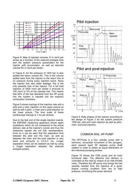
Figure 9 shows tracings of the injection rate with a<br />
pilot and a main injection on the upper picture as<br />
well as with a pilot-, a main and a post-injection on<br />
the lower picture. The time scale of these<br />
oscilloscope tracings is 1 ms per division.<br />
Due to the fast end of the single injection events,<br />
the EMI3000 measuring apparatus shows again<br />
oscillations which do not correspond to the actual<br />
delivery rate at the injector’s nozzle and thus the<br />
measured signals are not fully representative.<br />
Even so it can be seen that the separation time<br />
between the pilot and the main, as well as<br />
between the main and the post injection is very<br />
short and amounts to 0.2-0.3 ms. Longer<br />
separation times can be realized as well by using<br />
a longer separation between the solenoid<br />
energize pulses.<br />
Figure 9: Rate shapes of the injector according to<br />
the design of Figure 3 for the system pressure<br />
1500 bar; pilot and main injection as well as pilot-,<br />
main- and post-injection.<br />
COMMON RAIL HP-PUMP<br />
The HP-Pump is a four cylinder pump with a<br />
harmonic, sinusoidal movement of the plungers,<br />
each spaced apart 90 degrees pump shaft<br />
rotation in order to obtain an equal distribution of<br />
the individual pumping strokes.<br />
Figure 10 shows the <strong>CRS</strong> pump and its main<br />
functional data. The effective fuel delivery is<br />
controlled at the inlet by means of an inlet throttle<br />
valve. Therefore the HP-pump only brings the fuel<br />
quantity needed from the injectors at a given<br />
engine running condition from low to high<br />
pressure, minimizing the power demand.<br />
© CIMAC Congress 2007, Vienna Paper No. <strong>70</strong> 6