POOL SITE INSPECTION FACILITY (PSIF) AT DHRUVA - BARC
POOL SITE INSPECTION FACILITY (PSIF) AT DHRUVA - BARC
POOL SITE INSPECTION FACILITY (PSIF) AT DHRUVA - BARC

Create successful ePaper yourself
Turn your PDF publications into a flip-book with our unique Google optimized e-Paper software.
No. 233<br />
June<br />
2003<br />
<strong>POOL</strong> <strong>SITE</strong> <strong>INSPECTION</strong> <strong>FACILITY</strong> (<strong>PSIF</strong>)<br />
<strong>AT</strong> <strong>DHRUVA</strong><br />
J. Subba Raju, S. Duraisamy, A.K. Saha and A.C. Tikku<br />
Reactor Group<br />
and<br />
M.G. Andhansare<br />
Formerly in Reactor Group<br />
Introduction<br />
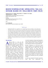
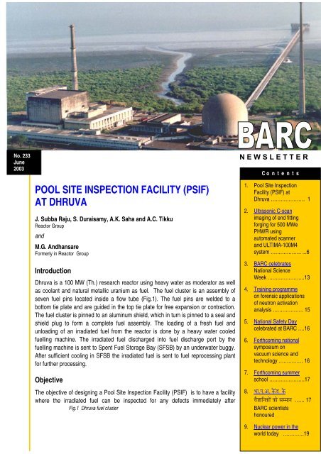
Dhruva is a 100 MW (Th.) research reactor using heavy water as moderator as well<br />
as coolant and natural metallic uranium as fuel. The fuel cluster is an assembly of<br />
seven fuel pins located inside a flow tube (Fig.1). The fuel pins are welded to a<br />
bottom tie plate and are guided in the top tie plate for free expansion or contraction.<br />
The fuel cluster is pinned to an aluminum shield, which in turn is pinned to a seal and<br />
shield plug to form a complete fuel assembly. The loading of a fresh fuel and<br />
unloading of an irradiated fuel from the reactor is done by a heavy water cooled<br />
fuelling machine. The irradiated fuel discharged into fuel discharge port by the<br />
fuelling machine is sent to Spent Fuel Storage Bay (SFSB) by an underwater buggy.<br />
After sufficient cooling in SFSB the irradiated fuel is sent to fuel reprocessing plant<br />
for further processing.<br />
Objective<br />
The objective of designing a Pool Site Inspection Facility (<strong>PSIF</strong>) is to have a facility<br />
where the irradiated fuel can be inspected for any defects immediately after<br />
Fig.1 Dhruva fuel cluster<br />
N E W S L E T T E R<br />
C o n t e n t s<br />
1. Pool Site Inspection<br />
Facility (<strong>PSIF</strong>) at<br />
Dhruva ………………… 1<br />
2. Ultrasonic C-scan<br />
imaging of end fitting<br />
forging for 500 MWe<br />
PHWR using<br />
automated scanner<br />
and ULTIMA-100M4<br />
system ………………. ...6<br />
3. <strong>BARC</strong> celebrates<br />
National Science<br />
Week …………………..13<br />
4. Training programme<br />
on forensic applications<br />
of neutron activation<br />
analysis ………………. 15<br />
5. National Safety Day<br />
celebrated at <strong>BARC</strong> ….16<br />
6. Forthcoming national<br />
symposium on<br />
vacuum science and<br />
technology …………… 16<br />
7. Forthcoming summer<br />
school ………………….17<br />
8. ž¸¸.œ¸.‚. ˆ½Å¿Í ˆ½Å<br />
¨¸¾±¸¸¹›¸ˆÅ¸½¿ ˆÅ¸½ ¬¸ŸŸ¸¸›¸ …... 17<br />
<strong>BARC</strong> scientists<br />
honoured<br />
9. Nuclear power in the<br />
world today ………….19
unloading from the reactor. In order to inspect the<br />
irradiated fuel assembly immediately after<br />
unloading from the reactor, wet transportation of<br />
fuel and an underwater inspection facility would<br />
be required if the inspection is carried out at a<br />
remotely located inspection laboratory.<br />
Alternatively, the irradiated fuel could be stored<br />
in a pool of water at reactor site and after<br />
sufficient cooling, it could be transported in dry<br />
condition to the remote inspection laboratory.<br />
Any inspection at a remotely located laboratory<br />
involves a long under water storage of irradiated<br />
fuel, which would result in shadowing of the<br />
primary defects thereby loosing vital information<br />
on the root cause responsible for initiating the<br />
primary defect and will also result in loss of time<br />
to acquire the useful data for any remedial action.<br />
Hence, it was decided to have an under-water<br />
inspection facility in the spent fuel storage bay of<br />
Dhruva Reactor for inspection of irradiated fuel<br />
assemblies.<br />
Guidelines for Design of <strong>PSIF</strong><br />
The following guidelines were followed while<br />
designing the pool site inspection facility.<br />
• The design should be simple and reliable for<br />
under water operation and inspection of<br />
irradiated fuel assembly at a water depth of<br />
4100 mm.<br />
• The radiation exposure of the operation and<br />
maintenance personnel should meet the<br />
principle of ALARA (as low as reasonably<br />
achievable)<br />
• The disturbance in fuel storage bay water<br />
should be minimum so as to minimise air<br />
borne activity.<br />
• The bay water should not get contaminated<br />
with impurities like oil, grease, corrosion<br />
products, etc. while performing underwater<br />
operations.<br />
• Fuel pins should not get damaged during<br />
under water longitudinal slitting and end<br />
cutting of fuel cluster.<br />
• The design should facilitate separation of<br />
irradiated fuel pins manually using remotely<br />
operated tools.<br />
• The radioactive metallic dust generated<br />
during fuel assembly cutting operations<br />
should be contained in the tank.<br />
• Decontamination of facility should be<br />
•<br />
possible by proper selection of material.<br />
Easy maintenance and quick replacement of<br />
equipment and component should be<br />
possible.<br />
• Maintenance and repair activities should be<br />
kept to a bare minimum.<br />
• Remote handling tools should be rugged<br />
and simple to operate.<br />
• Safe transportation of fuel pins after<br />
inspection should be possible.
Based on the above guidelines a pool Site<br />
Inspection Facility (<strong>PSIF</strong>) was designed,<br />
fabricated and installed in SFSB of Dhruva<br />
Reactor.<br />
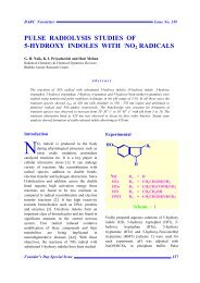
Major Components of <strong>PSIF</strong><br />
The description of some of the major components<br />
of <strong>PSIF</strong> (Fig. 2) are as follows:<br />
Container tank<br />
A container tank of overall dimensions 5200 mm<br />
(length) x 1000 mm (width) x 300 mm (height)<br />
houses all the equipments and components<br />
required for <strong>PSIF</strong>. The tank is fabricated out of<br />
SS-304 L plates. Stiffeners are provided at the<br />
Fig.2 General layout<br />
tank bottom for strengthening it so as to minimise<br />
deflection of the tank while handling. Drain hole<br />
fitted with a removable type fine filter is provided<br />
at the bottom of the tank for collection of<br />
radioactive metallic dust generated during cutting<br />
operations.<br />
Guide rails<br />
Stainless steel guide rails for longitudinal<br />
movement of the cutting mechanism mounted on<br />
a buggy are provided at a span of 850 + 0. 5 mm.<br />
The guide rails are fixed to the container tank.<br />
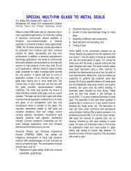
Buggy and buggy drive<br />
A buggy of overall size 850 mm X 660 mm X<br />
1065 mm (height) (Fig. 3) is fabricated from SS
material and has four corner wheels for<br />
longitudinal movement. The buggy provides<br />
support for the cutter motor and the cutting<br />
mechanism for longitudinal slitting and end<br />
cutting of fuel cluster. SS roller chain and<br />
sprocket drive are provided for buggy movement<br />
in longitudinal direction. The drive sprockets are<br />
located at both the ends of guide rails and<br />
manually operated through a bevel gear drive<br />
arrangement.<br />
Fig.3 Buggy with cutting mechanism<br />
Roller assembly<br />
Irradiated fuel cluster of 3525 mm length rests<br />
horizontally on three sets of roller assemblies so<br />
that the fuel cluster can be rotated for underwater<br />
longitudinal slitting. A common shaft connects the<br />
drive roller of each roller assembly. The drive<br />
roller shaft is rotated manually through a bevel<br />
gear arrangement.<br />
Orientation-cum-guiding fixture<br />
Clamping vice<br />
The fuel cluster is clamped by 2 vices during<br />
slitting operation. Each vice has a fixed and a<br />
moving jaw. The moving jaw of vice is moved in<br />
As the seven fuel pins of the fuel cluster are<br />
located inside a flow tube, it is difficult to know<br />
their orientation from outside of flow tube.<br />
An orientation-cum-guiding fixture has been<br />
Fig.4 Dhruva fuel cluster cross section (with cutter<br />
location)<br />
designed to orient the fuel cluster so as to ensure<br />
safe longitudinal slitting operation of the flow tube<br />
without causing any damage to the uranium fuel<br />
pins (Fig.4). The orientation of the guiding fixture<br />
is carried out by taking reference of top end plugs<br />
of fuel pins projecting above the top tie plate. The<br />
orientation fixture is engaged to the fuel end<br />
plugs through seven internal holes (Fig. 5). Two<br />
sets of guide plates are provided 180º apart on<br />
external surface of the fixture to guide the cutting<br />
saw for longitudinal slitting operation. The guide<br />
plates are separated by 3.5 mm by which the<br />
cutting saw gets located automatically in between<br />
the adjacent fuel pins, thereby achieving safe<br />
longitudinal slitting of the fuel cluster.<br />
Fig. 5 Orientation-cum- guiding fixture (engaged to fuel<br />
cluster)
or out by a lead screw mechanism rotated<br />
manually through bevel gear arrangement.<br />
Longitudinal slitting and end cutting drive<br />
A circular cutting saw of 300 mm diameter and 2<br />
mm thickness is fixed to a canned motor through<br />
reduction bevel gear arrangement and the<br />
complete assembly is mounted on the buggy for<br />
longitudinal slitting and end cutting operation of<br />
fuel cluster. Canned motor of 3 kW capacity,<br />
supplied by Control Instrumentation Division,<br />
<strong>BARC</strong>, is assembled with the cutting saw which<br />
can be rotated by a lead screw mechanism and<br />
indexed by 90 0 for change over from longitudinal<br />
slitting to end cutting operation and vice versa.<br />
Mechanical stoppers are provided for controlling<br />
the depth of cutting for longitudinal slitting and<br />
end cutting operations. Guide rods and ball guide<br />
bearings are provided to guide the motor and the<br />
cutting saw during vertical feeding for slitting and<br />
FUEL PIN CLAD FAILURE<br />
end cutting operation. Underwater feeding,<br />
indexing and clamping of the motor along with the<br />
cutter assembly are carried out manually, by<br />
remotely operated tools.<br />
Inspection rack<br />
The fuel pins are stored underwater in a rack<br />
provided on one side of the container tank after<br />
separation from the fuel cluster. The fuel pins can<br />
be handled underwater with remotely operated<br />
tools for various inspections to check for any<br />
defects.<br />
Tools for underwater operations<br />
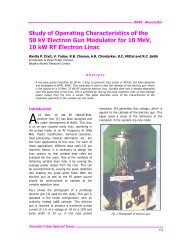
Fig. 6 Underwater PIE of Dhruva fuel cluster at <strong>PSIF</strong><br />
As the underwater operations for <strong>PSIF</strong> are to be<br />
carried out remotely in manual mode, different<br />
types of tools, each 6 meters long, have been<br />
designed to carry out various underwater<br />
operations like:
• Roller drive to align the fuel cluster along<br />
with orientation fixture for longitudinal<br />
slitting.<br />
• Vice drive for fuel assembly clamping.<br />
• Feed drive of cutting saw for longitudinal<br />
slitting and end cutting.<br />
• Buggy drive for longitudinal movement of the<br />
cutting saw.<br />
• Unlocking of cutting saw clamps and release<br />
of anti-rotation latch.<br />
• Rotation & Indexing of cutting saw for<br />
longitudinal slitting & end cutting operation<br />
and vice versa.<br />
• Separation and storage of fuel pins in the<br />
rack for inspection.<br />
• Loading of separated fuel pins in a can for<br />
disposal.<br />
Under-water Post Irradiation<br />
Examination (PIE) at <strong>PSIF</strong><br />
After extensive trials, the <strong>PSIF</strong> was installed and<br />
commissioned in SFSB and visual inspection of<br />
an irradiated fuel assembly was carried out.<br />
Visual inspection<br />
An irradiated fuel assembly having confirmed<br />
clad failure was longitudinally slit and ends were<br />
cut underwater at <strong>PSIF</strong> and the fuel pins were<br />
separated for visual inspection. The visual<br />
inspection revealed a defect of around 50 mm<br />
length on one of the fuel pin (Fig.6). Uranium and<br />
aluminum clad material was found missing from<br />
the defect location and this observation was<br />
recorded by an underwater video camera. The<br />
root cause for clad failure is under investigation.<br />
Non-destructive testing<br />
In order to extend the scope of underwater<br />
inspection, various other non-destructive tests<br />
like Eddy Current Testing and Ultrasonic testing<br />
etc. are planned in future at Dhruva Pool Site<br />
Inspection Facility for underwater inspection of<br />
irradiated fuel assemblies.<br />
The successful design, fabrication and testing of<br />
Dhruva <strong>PSIF</strong> was done by Research Reactor<br />
Services Division (RRSD) and the satisfactory<br />
installation and commissioning of <strong>PSIF</strong> was done<br />
by Reactor Operation Division (ROD) & RRSD of<br />
Reactor Group, <strong>BARC</strong>.