CGH23/25 SPM-708
CGH23/25 SPM-708
CGH23/25 SPM-708

You also want an ePaper? Increase the reach of your titles
YUMPU automatically turns print PDFs into web optimized ePapers that Google loves.
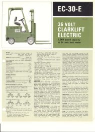
<strong>CGH23</strong>/<strong>25</strong><br />
Pallet Truck<br />
Operator / Parts & Service Manual<br />
Copyrighted Material<br />
Intended for CLARK dealers only<br />
Do not sell or distribute<br />
OPM-<strong>708</strong>
INSTRUCTIONS<br />
RAISE POSITION<br />
Depress the lever and pump handle until pallet has reached the desired height. A Clearance of 1” between the floor and<br />
pallet is usually sufficient to move the load. Do not lift the load with one fork or extremity of the forks.<br />
NEUTRAL POSITION<br />
The neutral position is found between the raise and lower position. This neutral (drive) position disengages the lifting<br />
mechanism making the handle free from hydraulic resistance and becomes almost weightless, yet the forks retain their<br />
raised position. Always use the neutral position when moving a load.<br />
LOWER POSITION<br />
Pull the lever up to lower the forks. The lever is spring loaded for lowering only, therefore when you release the lever it<br />
will automatically return to the neutral position.<br />
WARNING<br />
For safe operation of Hand Pallet Trucks, please read the following instructions:<br />
1. Do not operate a Hand Pallet Truck unless you are familiar with it and have been trained and authorized to do so. Read<br />
all warnings and instructions here and on the truck.<br />
2. Do not operate a Hand Pallet Truck until you have checked its condition. Give special attention to the wheels, handle,<br />
forks, lift and lower control.<br />
3. Do not operate a damaged or faulty truck. Do not attempt repairs unless you are trained and authorized to do so.<br />
4. Operate Hand Pallet Trucks only from the designated operating position. Never place any part of your body in the<br />
lifting mechanism or under the forks or load. Do not carry passengers.<br />
5. Do not handle unstable or loosely stacked loads. Use special care when handling long, high or wide loads to avoid<br />
losing the load, striking bystanders, or tipping the truck.<br />
6. Do not overload the truck. Check capacity plate for carrying capacity information. Overloading may cause truck to<br />
perform incorrectly.<br />
7. The capacity of the truck assumes an evenly distributed load with the center of the load being at the halfway point of<br />
the length of the forks.<br />
8. Make sure that the length of the forks matches the length of the pallet. Using a pallet truck where the forks are longer<br />
than the pallet will damage the truck if the pallet truck is pushed through the pallet and the forks are under a second<br />
pallet behind the one being lifted. When lowering the load, make sure the area where the pallet is to be placed is clear.<br />
9. Observe traffic regulations. Yield right of way to pedestrians. Stop at cross aisles.<br />
10. Hand Pallet Trucks are for general operation on level, flat hard surfaces.<br />
FAILURE TO FOLLOW THESE INSTRUCTIONS MAY CAUSE SERIOUS INJURY TO THE<br />
OPERATOR OR OTHERS.<br />
THREE-MONTH MAINTENANCE SCHEDULE<br />
1) Check oil level.<br />
2) Lubrication-joints, pins, axles, pushrods, steering wheel bearings with good molybdenum type grease.<br />
ORDERING PARTS<br />
The <strong>CGH23</strong>/<strong>25</strong> Hand Pallet Trucks are distributed through CLARK dealers that are eager and capable to service your<br />
equipment. Whenever parts, adjustments, or repairs are needed, please call your local CLARK dealer. When doing so<br />
“please be sure to give them your truck model number and use part numbers and nomenclature as shown in the following<br />
pages. Adherence to the above procedure will save time and provide speedy assistance when it counts.<br />
Copyrighted Material<br />
Intended for CLARK dealers only<br />
Do not sell or distribute
Handle Assembly Instructions<br />
1) Make sure the symbols on the handle and<br />
on the pump are the same.<br />
(3) Place handle onto pump<br />
body and pull the chain from<br />
handle. Tap shaft into place<br />
(1-12).<br />
(4) Install roll pin and then<br />
set screw into the<br />
shaft.<br />
(6) Connect the chain with<br />
spring clip (1-38). (7) Remove the pin from<br />
pump.<br />
Copyrighted Material<br />
Intended for CLARK dealers only<br />
Do not sell or distribute<br />
(2) Remove the set screw 1-21 and roll pin (1-<br />
21), Tap out shaft (1-12).<br />
(5) Insert chain through shaft.<br />
(8) Pump the handle about<br />
10 times while holding<br />
lever in the lower<br />
position to bleed any air<br />
from the system.
39<br />
14-4<br />
36<br />
2<br />
3<br />
4<br />
5<br />
6<br />
Handle Assembly<br />
HO<br />
Pump Assembly<br />
PO<br />
14-1<br />
7 12<br />
PALLET JACK <strong>CGH23</strong>/<strong>25</strong> - 1<br />
Item Part No. Qty.Description<br />
1 4155449 1 Handle & Pump Complete<br />
HO 4575294 1 Handle Assy<br />
PO 4575261 1 Pump Assy<br />
2 4155353 2 Spring Pin<br />
3 4155450 1 Bearing<br />
4 4155354 2 Spring Pin<br />
5 4155451 1 Pressure Plate<br />
6 4155355 1 Circlip<br />
7 4155452 1 Wheel Shaft<br />
9 4155357 2 Washer<br />
10 1806274 2 Wheel (rubber)<br />
10-1 1806275 2 Wheel (Poly, aluminum rim)<br />
10-2 1806276 2 Wheel (Poly, iron rim)<br />
10-3 1806277 2 Wheel (nylon)<br />
10-4 1806278 2 Wheel with bearings (rubber)<br />
10-5 1806279 2 Wheel w/bearings (Poly, aluminum rim)<br />
10-6 1806280 2 Wheel w/ bearings (Poly, iron rim) (Standard)<br />
10-7 1806281 2 Wheel with bearings (nylon)<br />
11 4155359 2 Circlip<br />
12 4155360 2 Arm Pin<br />
13 1806287 1 Lift Arm (fork width 685mm)<br />
13-1 4155455 1 Lift Arm (fork width 540mm)<br />
13-2 1806288 1 Lift Arm (fork width 520mm)<br />
14 4155456 2 Copper Bush<br />
14-1 4575295 2 Copper Bush<br />
14-2 4575296 2 Copper Bush<br />
14-3 4575297 4 Copper Bush<br />
14-4 4575298 2 Copper Bush<br />
15 4155361 2 Spring Pin<br />
16 1806289 2 Push Rod<br />
17 4155458 4 Spring Pin<br />
18 4155459 4 Exit Roller<br />
19 4155460 2 Spring Pin<br />
10<br />
32<br />
13<br />
38<br />
14<br />
Copyrighted Material<br />
Intended for CLARK dealers only<br />
Do not sell or distribute<br />
15<br />
9 11<br />
33 34 35<br />
14-2<br />
19<br />
40<br />
20<br />
16<br />
14-3<br />
35-1<br />
34-1<br />
33-1<br />
22<br />
21<br />
27<br />
30<br />
31<br />
18<br />
July 05<br />
Item Part No. Qty.Description<br />
20 4155461 2 Shaft<br />
21 4155462 2 Load Wheel Frame<br />
22 4155463 2 Spring Pin<br />
<strong>25</strong> 4155464 2 Shaft<br />
26 4155465 2 Shaft<br />
27 4155364 4 Washer<br />
28 1806290 2 Load Wheel (Poly) (Std-Single)<br />
28-1 1806291 2 Load Wheel (Nylon) (Std-Single)<br />
28-2 1806292 2 Load Wheel with bearings (Poly) (Std)<br />
28-3 1806293 2 Load Wheel with bearings (Nylon)<br />
29 4155466 2 Opt Tandem Load Wheel Assy (Poly)<br />
29 4155467 2 Opt Tandem Load Wheel Assy (White Nylon)<br />
29 4155468 2 Opt Tandem Load Wheel Assy (Black Nylon)<br />
30 4155366 2 Circlip<br />
31 1806294 1 Long Shaft (fork width 685mm)<br />
31-1 4155469 1 Long Shaft (fork width 540mm)<br />
31-2 1806295 1 Long Shaft (fork width 520mm)<br />
32 4155470 1 Fork Body (fork width 685mm)<br />
32-1 1806571 1 Fork Body (fork width 540mm)<br />
32-2 1806572 1 Fork Body (fork width 520mm)<br />
33 4155471 2 Circlip<br />
33-1 1806826 2 Nut (serial #88614-93065 only)<br />
34 4155472 2 Entry Roller<br />
34-1 1806828 2 Entry Roller (serial #88614-93065 only)<br />
35 4155473 2 Shaft<br />
35-1 1806827 2 Bolt (serial #88614-93065 only)<br />
36 4575246 1 Cap of Bearing<br />
37 4575288 4 Opt Tandem Load Wheel (White Nylon)<br />
37-1 4575229 4 Opt Tandem Load Wheel (Black Nylon)<br />
37-2 4575227 4 Opt Tandem Load Wheel (Poly)<br />
38 1806541 2 CLARK Decal (black)(on fork body)<br />
39 1806542 1 CLARK Decal (white)(on handle)<br />
40 1806698 2 Hub Cap<br />
28<br />
<strong>25</strong><br />
17<br />
26<br />
37<br />
29
PUMP SEAL<br />
KIT<br />
1-4<br />
1-5<br />
1-7<br />
1-7A<br />
1-8<br />
1-9<br />
1-8A<br />
1-9A<br />
1-9B<br />
PALLET JACK<br />
1-2<br />
1-1<br />
1-0<br />
1-10<br />
1-11<br />
1-6<br />
1-3<br />
1-13<br />
1-14<br />
1-12<br />
1-21<br />
1-24<br />
1-23<br />
Item Part No. Qty.Description<br />
1-0 1806297 1 Seal Kits<br />
1-1 4155432 1 Stop Rubber<br />
1-2 4155433 1 Spring Pin<br />
1-3 4155434 1 Handle<br />
1-4 4155367 1 Spring Pin<br />
1-5 4155368 1 Spring Pin<br />
1-6 4155369 1 Lowering Lever (Finger Tip)<br />
1-7 4155370 1 Linkage<br />
1-7A 1806833 1 Linkage (serial #88614-93065 only)<br />
1-8 4155371 1 Chain<br />
1-8A 1806832 1 Chain (serial #88614-93065 only)<br />
1-9 4155372 1 Chain Rod<br />
1-9A 1806830 1 Rod (serial #88614-93065 only)<br />
1-9B 13DM00004 1 Nut (serial #88614-93065 only)<br />
1-10 4155373 1 Pressure Roller<br />
1-11 4155374 1 Shaft<br />
1-12 4155495 1 Shaft<br />
1-13 4155375 2 Spring Pin<br />
1-13A 1806834 1 Spring Pin (serial #88614-93065 only)<br />
1-14 4155376 1 Spring Plate<br />
1-14A 1806829 1 Spring Plate (serial #88614-93065 only)<br />
1-16 4155436 1 Spring Cap<br />
1-17 4155437 1 Spring<br />
1-18 4155438 1 Plunger Assy<br />
1-19 4155378 1 Seal DH18<br />
1-20 4155379 1 Seal DH18<br />
1-21 4155439 1 Screw<br />
(1-21) 4575299 1 Spring Pin<br />
1-22 4155934 1 Pump Body<br />
1-16<br />
1-17<br />
1-18<br />
1-19<br />
1-20<br />
1-32<br />
1-21<br />
1-22<br />
1-14A<br />
1-13A<br />
Copyrighted Material<br />
Intended for CLARK dealers only<br />
Do not sell or distribute<br />
1-44<br />
1-45<br />
1-30<br />
B2-21<br />
1-50 B2-22<br />
1-<strong>25</strong><br />
1-27<br />
1-26<br />
1-28<br />
1-31<br />
1-33<br />
1-36<br />
1-46<br />
1-37<br />
1-47<br />
1-42<br />
Item Part No. Qty.Description<br />
1-23 4155441 2 Washer<br />
1-24 4155442 2 Screw Plug<br />
1-<strong>25</strong> 4155380 1 O-Ring<br />
1-26 4155381 1 Seal UN32<br />
1-27 4155443 1 Screw<br />
1-28 4155444 1 Pump Cap<br />
1-29 4155382 1 O-Ring P62<br />
1-30 4155383 1 Ball 3/4<br />
B2-21 4575300 1 Washer<br />
B2-22 4575301 1 Circlip<br />
1-31 4155445 1 Cylinder<br />
1-32 4155384 1 O-Ring P31<br />
1-33 4155385 1 Seal UN32<br />
1-34 4155446 1 Pin<br />
1-35 4155386 1 O-Ring<br />
1-36 4155387 1 O-Ring<br />
1-37 4155388 1 O-Ring<br />
1-38 4155447 1 Activator<br />
1-39 4155389 1 Bolt<br />
1-40 4155390 1 Nut<br />
1-41 4155391 1 Spring Pin<br />
1-42 4155448 1 Valve Assy<br />
1-43 4155392 1 O-Ring<br />
1-44 4155393 1 Washer<br />
1-45 4155394 1 Bolt<br />
1-46 4575243 1 Pu Washer<br />
1-47 4575244 1 Pu Washer<br />
1-50 4575245 1 Over Load Valve Assy<br />
1-51 1806817 1 Cylinder Tool<br />
1-38<br />
1-29<br />
1-34<br />
1-51<br />
1-39<br />
1-35<br />
1-40<br />
1-43<br />
1-41<br />
<strong>CGH23</strong>/<strong>25</strong> - 2 July 05
The Principal of the Hydraulic Pump<br />
TROUBLESHOOTING AND SERVICE<br />
Lifting<br />
1. With the lever in the lift position – Raise the handle<br />
Hydraulic oil flows from the reservoir through Channel A, open Ball<br />
A, and into the pump housing through Channel B.<br />
2. Lowering the handle – the Ball A closes, Ball B opens. The piston,<br />
through Channel B and Channel C, forces oil to the Lift Cylinder. The<br />
cylinder extends lifting the forks.<br />
Lowering<br />
1. Pull the lever into the Lower position.<br />
2. Part (1-39) moves the D1 inward. Ball A and Ball B open and oil is<br />
released from the loft cylinder back to the reservoir through Channel C,<br />
Ball B, Ball A and Channel A.<br />
Transporting<br />
1. Place the lever in the neutral position. Part 1-39 depresses partially to<br />
open Ball A.<br />
2. Raising the handle - oil flow from the reservoir to the pump housing<br />
through Channel A.<br />
3. Lowering the handle – oil will flow to the reservoir from the lift pump<br />
through Channel B, Ball A and Channel A.<br />
Copyrighted Material<br />
Intended for CLARK dealers only<br />
Do not sell or distribute
Troubleshooting<br />
1. Truck will not lift<br />
Check the following<br />
1.1 Bleed the air from the Pump<br />
Place the lever in the Lower<br />
position and pump the handle 10<br />
times (Fig 1.1.1).<br />
1.2 Check the chain (1-8)<br />
If it is not positioned over the<br />
shaft (1-12), reposition it.<br />
1.3 Check the Symbols<br />
The symbol on the handle and<br />
pump must be the same (Fig<br />
1.3.1)<br />
1.4 Adjust the valve<br />
a. Release the screw (1-40) (Fig<br />
1.4.1)<br />
b. Adjust the screw (1-39)<br />
counter clockwise (Fig 1.4.2)<br />
Check to see if unit will lift. If<br />
unit lifts, continue with next<br />
step. If unit does not lift, jump<br />
to step 1.5.<br />
Lift the truck to top position.<br />
Hold lever as shown in Fig<br />
1.4.3, turn adjuster (1-39)<br />
clockwise until the truck starts<br />
to lower.<br />
Tighten lock nut (1-40).<br />
Fig 1.4.3<br />
Copyrighted Material<br />
Intended for CLARK dealers only<br />
Do not sell or distribute<br />
Fig 1.4.2<br />
Fig 1.1.1<br />
Fig 1.3.1<br />
Fig 1.4.1
Fig 1.5.4<br />
1.5 Replace the Valve Assembly<br />
Turn truck onto its side (Fig 1.5.1)<br />
Tap out roll pin (1-14) and remove the<br />
lowering lever (1-38) (Fig 1.5.2)<br />
Push the lift cylinder to its full raised<br />
position (Fig 1.5.3)<br />
Remove the copper bushing (1-42) from<br />
the valve assembly (Fig 1.5.4)<br />
Remove the valve core (1-42) (Fig 1.5.5)<br />
Install new Valve Core (1-42) including<br />
new copper bushing.<br />
Install roll pin (1-38).<br />
Return to Step 1.4 for final adjustments.<br />
Fig 1.5.5<br />
Copyrighted Material<br />
Intended for CLARK dealers only<br />
Do not sell or distribute<br />
Fig 1.5.1<br />
Fig 1.5.3<br />
Fig 1.5.2
2. Excessive Lift Drift<br />
Fig 2.1.4<br />
2.1 Replace Seals 1-33<br />
Remove snap ring B2-22 (Fig 2.1.1)<br />
Fig 2.1.6<br />
Remove 3 retaining screws 1-27 (Fig 2.1.2)<br />
Lift fork frame from top of pump unit (Fig<br />
2.1.3)<br />
Pull the lift piston from the pump assembly<br />
1-31 (Fig 2.1.4)<br />
Remove cap from top of cylinder (Fig 2.1.5)<br />
Drain oil from cylinder (Fig 2.1.6)<br />
Remove and replace the piston seal 1-33<br />
(Fig 2.1.7)<br />
Reassemble and fill with hydraulic oil and<br />
then test.<br />
Fig 2.1.5<br />
Copyrighted Material<br />
Intended for CLARK dealers only<br />
Do not sell or distribute<br />
Fig 2.1.1<br />
Fig 2.1.2<br />
Fig 2.1.3<br />
Fig 2.1.7
3. Will Not Lower<br />
4. Leaks<br />
3.1 Check the chain 1-8<br />
Check for broken chain, replace.<br />
Check to see that the shaft 1-12 is held<br />
in place by screw 1-21. If shaft has been<br />
free to rotate, then the chain will have<br />
been damaged by the rotation of the<br />
shaft when pumping the handle.<br />
If the chain checks OK, continue below.<br />
3.2 Replace valve assembly 1-42.<br />
Refer to step 1.5<br />
4.1 Leak from piston<br />
Remove piston spring 1-17 (Fig 4.1.1)<br />
Replace seal 1-19 & 1-20 (Fig 4.1.2)<br />
4.2 Leak from piston carriage<br />
Remove piston spring 1-17 (Fig 4.1.1)<br />
Remove piston assembly 1-18 (Fig<br />
4.2.1)<br />
Replace seal 1-32<br />
Fig 4.2.1<br />
Copyrighted Material<br />
Intended for CLARK dealers only<br />
Do not sell or distribute<br />
Fig 4.1.1<br />
Fig 4.1.2
5. Wheel Problem<br />
5.1 Problem with Steer Wheel<br />
Remove the wheel cap (Fig 5.1.1)<br />
Remove snap ring 11 (Fig 5.1.2)<br />
Replace steer wheel<br />
5.2 Load Wheel Replacement<br />
Tap out the roll pin 22 (Fig 5.2.1)<br />
Tap shaft out of carrier (Fig 5.2.2)<br />
Replace load wheel<br />
Fig 5.2.1<br />
Copyrighted Material<br />
Intended for CLARK dealers only<br />
Do not sell or distribute<br />
Fig 5.1.1<br />
Fig 5.1.2<br />
Fig 5.2.2
6. Change or Add Oil<br />
6.1 Change oil in reservoir<br />
Remove snap ring B2-22 (Fig 2.1.1)<br />
Remove 3 retaining screws 1-27 (Fig 2.1.2)<br />
Lift fork frame from top of pump unit (Fig<br />
2.1.3)<br />
Pull the lift piston from the pump assembly 1-<br />
31 (Fig 2.1.4)<br />
Remove cap from top of cylinder (Fig 2.1.5)<br />
Drain oil from cylinder (Fig 2.1.6)<br />
Fig 2.1.3<br />
Fig 2.1.5<br />
Copyrighted Material<br />
Intended for CLARK dealers only<br />
Do not sell or distribute<br />
Fig 2.1.4<br />
Fig 2.1.6<br />
Fig 2.1.2<br />
Fig 2.1.1
6.2 Add Oil<br />
Remove all three of the retaining screws 1-27<br />
(Fig 6.2.1)<br />
Lift up pump cap 1-28 to add oil as shown<br />
(Fig 6.2.2)<br />
Fig 6.2.1<br />
Fig 6.2.2<br />
Copyrighted Material<br />
Intended for CLARK dealers only<br />
Do not sell or distribute