FG Falcon A/C system - Repco Trade Zone
FG Falcon A/C system - Repco Trade Zone
FG Falcon A/C system - Repco Trade Zone

Create successful ePaper yourself
Turn your PDF publications into a flip-book with our unique Google optimized e-Paper software.
Technically Speaking AUTOMOTIVE ELECTRICAL & AIR CONDITIONING NEWS<br />
<strong>FG</strong> <strong>Falcon</strong> A/C <strong>system</strong><br />
The Auto-Tech Technical Helpline has been receiving a number of<br />
enquiries on the <strong>FG</strong> <strong>Falcon</strong> A/C <strong>system</strong>, particularly with regard<br />
to the correct refrigerant charge.<br />
With the introduction of the <strong>FG</strong> <strong>Falcon</strong> range, came significant<br />
changes to the HVAC System (Heating Ventilation and Air<br />
Conditioning) over the previous BA to BFII models.<br />
<strong>FG</strong> models are available with one of three HVAC <strong>system</strong>s:<br />
• Heater Only Manual HVAC (no A/C) - option on some Utes.<br />
• Single <strong>Zone</strong> Automatic Climate Control.<br />
• Dual <strong>Zone</strong> Automatic Climate Control (driver and front<br />
passenger zones).<br />
The TXV Returns....<br />
With these <strong>system</strong>s came another significant change. Gone is the<br />
old Orifice Tube as a means of controlling refrigerant flow. The<br />
TXV makes its return in this “Cycling Clutch TXV A/C System”.<br />
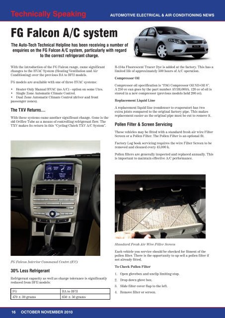
<strong>FG</strong> <strong>Falcon</strong> Interior Command Centre (ICC)<br />
30% Less Refrigerant<br />
Refrigerant capacity as well as charge tolerance is significantly<br />
reduced from BFII models:<br />
<strong>FG</strong> BA to BFII<br />
470 ± 30 grams 650 ± 50 grams<br />
16 OCTOBER NOVEMBER 2010<br />
R-134a Fluorescent Tracer Dye is added at the factory. This has a<br />
limited life of approximately 500 hours of A/C operation.<br />
Compressor Oil<br />
Compressor oil specification is “PAG Compressor Oil ND-Oil 8”.<br />
A 250 cc can goes by the part number AY19L000A. 120 cc of oil is<br />
stored in a new compressor (previous models held 200 cc).<br />
Replacement Liquid Line<br />
A replacement liquid line (condenser to evaporator) has two<br />
extra joints compared to the original factory pipe. This makes<br />
replacement easier as the original pipe must be cut to remove it.<br />
Pollen Filter & Screen Servicing<br />
These vehicles may be fitted with a standard fresh air wire Filter<br />
Screen or a Pollen Filter. The Pollen Filter is an optional fit.<br />
Factory Log book servicing requires the wire Filter Screen to be<br />
removed and cleaned every 45,000 k.<br />
Pollen filters are generally inspected and replaced annually. This<br />
is important to maintain effective A/C performance.<br />
Standard Fresh Air Wire Filter Screen<br />
Each vehicle you service should be checked for fitment of the<br />
pollen filter. There is the opportunity to up sell a pollen filter if<br />
not already fitted.<br />
To Check Pollen Filter<br />
1. Open glovebox and unclip limiting stop.<br />
2. Drop down glove box.<br />
3. Slide filter cover flap to the left.<br />
4. Remove filter or screen.
Technically Speaking AUTOMOTIVE ELECTRICAL & AIR CONDITIONING NEWS<br />
Slide Blower Cover to the left to access Filter<br />
Battery Reconnection Procedure<br />
If the battery has been disconnected, the Powertrain Control<br />
Module (PCM) reverts to the factory assembly Compressor Run-in<br />
Strategy.<br />
When the Run-in Strategy is in place, the PCM will switch OFF<br />
the Compressor clutch when engine speed exceeds 1,400 RPM.<br />
To reset Compressor strategy:<br />
1. Start engine<br />
2. Allow A/C to run at idle for at least 1 minute.<br />
3. Compressor operation returns to normal.<br />
The above situation can also occur if the vehicle has had a flat<br />
battery<br />
Remote Transmitters Store A/C Settings<br />
Each individual Remote key fob transmitter will retain the same<br />
A/C temperatures that were in use when that particular Remote<br />
was last used to lock the vehicle.<br />
Cooling Fan/s Run With Ignition OFF<br />
The cooling fan/s on <strong>FG</strong> may run for up to four minutes AFTER<br />
the ignition has been switched OFF.<br />
This is to minimise coolant loss during high heat soak loads.<br />
ENSURE THE BATTERY IS DISCONNECTED PRIOR TO<br />
UNDERTAKING WORK UNDER THE HOOD DURING THE FIRST<br />
FOUR MINUTES AFTER SWITCHING OFF THE IGNITION.<br />
Breathing Your Own Air Is Bad!<br />
It is important to remind customers not to operate the HVAC<br />
<strong>system</strong> for extended periods in the Recirculated mode. This will<br />
significantly reduce air quality in the vehicle cabin.<br />
New A/C System Components<br />
Virtually all components have changed on <strong>FG</strong>, including a<br />
new HVAC case and seals, Evaporator, Thermistor and Cabin<br />
Temperature Sensor. The new Ambient Temperature Sensor is<br />
located in the passenger side external mirror housing. It is not<br />
serviced separately from the mirror housing.<br />
The TXV is located at the end of the evaporator pipes on the<br />
engine side of the firewall.<br />
Sub-Cooled Condenser<br />
The new Condenser is a sub-cooled type and has an integral<br />
Receiver with Filter Drier. Refrigerant flow is now in two paths.<br />
In the main upper section of the core, the majority of refrigerant<br />
gas is condensed into a liquid. It then passes into the Receiver.<br />
From the bottom of the Receiver, liquid-only then flows out into<br />
the lower sub-cooled rows of the Condenser.<br />
Filter Drier Service Kit<br />
The Filter can be removed during service via an access cover<br />
at the lower edge of the front bumper bar. With the refrigerant<br />
evacuated, a screw-in plug at the base of the Receiver can be<br />
removed, allowing the Filter and Desiccant Sack to be removed.<br />
Ford say the each time the <strong>system</strong> is opened to the atmosphere,<br />
the Filter and Desiccant must be replaced. A new plastic screw-in<br />
plug comes with the Filter Service Kit.<br />
A/C System Controlled via CAN<br />
The A/C <strong>system</strong> is electronically controlled by the HVAC<br />
Integrated Module (or HIM). This is located behind the dash and<br />
can be accessed from the glovebox side. With <strong>FG</strong>, the HIM can<br />
now be removed without removing the dash.<br />
Switching of the Compressor Clutch Relay is controlled by the<br />
Powertrain Control Module (PCM).<br />
The A/C controls are physically situated on the lower part of the<br />
Interior Command Centre (ICC). These switches are hard wired to<br />
the Face Display Module located at the top of the ICC.<br />
The switch requests are then sent via the Mid Speed CAN Bus<br />
to the Instrument Cluster, then on the High Speed CAN Bus to<br />
the HVAC Integrated Module (HIM). This is a different CAN Bus<br />
configuration to the previous model.<br />
A/C Request Signal Communication to HVAC Module<br />
Regards from the Auto-Tech Team<br />
For more information contact <strong>Repco</strong> Auto-Tech on 1300 300<br />
352 or by Priority Fax on 1300 300 354<br />
OCTOBER NOVEMBER 2010 17