

Turn Off Snubber Design for High Frequency Modules - Microsemi
Turn Off Snubber Design for High Frequency Modules - Microsemi
Turn Off Snubber Design for High Frequency Modules - Microsemi

You also want an ePaper? Increase the reach of your titles
YUMPU automatically turns print PDFs into web optimized ePapers that Google loves.
<strong>Turn</strong>-<strong>Off</strong> <strong>Snubber</strong> <strong>Design</strong> <strong>for</strong> <strong>High</strong> <strong>Frequency</strong> <strong>Modules</strong><br />
<strong>Turn</strong>-off snubbers are passive circuits made of<br />
diodes, resistors and capacitors dedicated to<br />
storing energy <strong>for</strong> a short period to:<br />
- Decrease switch power losses during turnoff<br />
- Modify switching I-V diagram to fit safely<br />
within the switching safe operating area<br />
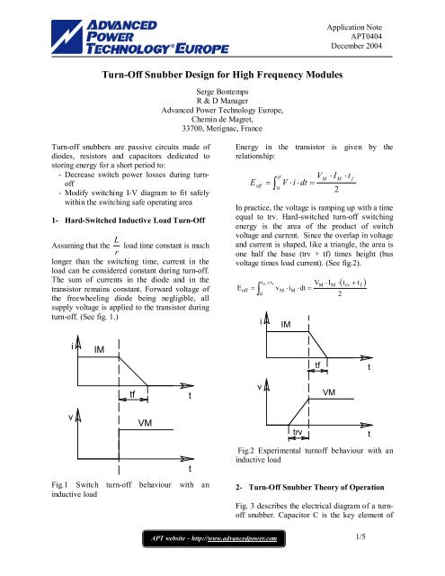
1- Hard-Switched Inductive Load <strong>Turn</strong>-<strong>Off</strong><br />
L<br />
Assuming that the load time constant is much<br />
r<br />
longer than the switching time, current in the<br />
load can be considered constant during turn-off.<br />
The sum of currents in the diode and in the<br />
transistor remains constant. Forward voltage of<br />
the freewheeling diode being negligible, all<br />
supply voltage is applied to the transistor during<br />
turn-off. (See fig. 1.)<br />
i<br />
v<br />
IM<br />
tf<br />
VM<br />
Fig.1 Switch turn-off behaviour with an<br />
inductive load<br />
Serge Bontemps<br />
R & D Manager<br />
Advanced Power Technology Europe,<br />
Chemin de Magret,<br />
33700, Merignac, France<br />
t<br />
t<br />
Application Note<br />
APT0404<br />
December 2004<br />
Energy in the transistor is given by the<br />
relationship:<br />
E<br />
off<br />
⋅ I<br />
2<br />
APT website www.advancedpower.com – http://www.advancedpower.com<br />
1/5<br />
= ∫<br />
tf<br />
0<br />
V<br />
V ⋅i<br />
⋅dt<br />
=<br />
M<br />
M<br />
⋅ t<br />
In practice, the voltage is ramping up with a time<br />
equal to trv. Hard-switched turn-off switching<br />
energy is the area of the product of switch<br />
voltage and current. Since the overlap in voltage<br />
and current is shaped, like a triangle, the area is<br />
one half the base (trv + tf) times height (bus<br />
voltage times load current). (See fig.2).<br />
f<br />
( )<br />
trv + tf<br />
V ⋅I ⋅ t + t<br />
Eoff = ∫ vM⋅iM⋅ dt =<br />
0<br />
2<br />
i<br />
v<br />
IM<br />
trv<br />
tf<br />
M M rv f<br />
VM<br />
Fig.2 Experimental turnoff behaviour with an<br />
inductive load<br />
2- <strong>Turn</strong>-<strong>Off</strong> <strong>Snubber</strong> Theory of Operation<br />
Fig. 3 describes the electrical diagram of a turnoff<br />
snubber. Capacitor C is the key element of<br />
t<br />
t
the circuit. The diode and resistor are only used<br />
to prevent instantaneous discharge of the energy<br />
stored in the capacitor while the switch turns on.<br />
Fig.3 Chopper with turn-off snubber circuit<br />
L<br />
As a first step in analyzing the operation of the<br />
snubber, we treat the current in the load during<br />
turn–off as constant. The turn-off sequence with<br />
the snubber is shown in Figure 4.<br />
IM<br />
VC<br />
t0 tf<br />
r<br />
C<br />
D<br />
VM<br />
I CAP<br />
Fig.4 <strong>Turn</strong> off behaviour with snubber circuit<br />
connected across the switch.<br />
During the time interval t0 to tf, current in the<br />
switch decreases while current in the capacitor<br />
increases such that the sum of the currents is<br />
constant.<br />
For simplicity, let us set the time at t0 equal to<br />
zero. At the end of the turn-off time tf, the<br />
voltage across the capacitor is calculated as the<br />
area of a triangle, given by the relationship:<br />
1<br />
V i dt V<br />
tf<br />
M f<br />
Ctf = C Ctf<br />
C∫ ⋅ ⇒ =<br />
(1)<br />
t0= 0<br />
2⋅C t2<br />
I ⋅ t<br />
R<br />
Application Note<br />
APT0404<br />
December 2004<br />
At the end of the interval tf to t2, the capacitor C<br />
is charged up to the voltage VM. It is only during<br />
the last phase (t > t2) that current switches from<br />
C to the freewheeling diode.<br />
During turn-off, snubber diode D conducts, and<br />
the voltage across the capacitor equals the<br />
voltage across the switch (ignoring the small<br />
voltage drop across the snubber diode). During<br />
the interval t0 to tf the capacitor current is<br />
IM ⋅t IM⋅t iC<br />
= = .<br />
tf − t0 tf<br />
The capacitor and switch voltage is<br />
2<br />
1 IM IM⋅t C = Czero Czero<br />
C∫ ⋅ ⋅ + = +<br />
tf 2⋅C⋅tf v t dt V V<br />
where VCzero is a constant of integration that is<br />
solved <strong>for</strong> by evaluating at t = tf.<br />
2<br />
IM⋅tf IM ⋅tf<br />
C = +<br />
t t<br />
Czero = +<br />
=<br />
Czero = Ctf<br />
f 2Ct ⋅ ⋅ f<br />
2C ⋅<br />
v V V V<br />
IM ⋅ tf<br />
Since VCtf<br />
= , VCzero must be zero.<br />
2C ⋅<br />
Substituting VCtf into the equation <strong>for</strong> vC, we get<br />
2<br />
2<br />
IM⋅tf t ⎛ t ⎞<br />
C = ⋅ =<br />
2 Ctf ⎜ ⎟<br />
2C ⋅ tf<br />
⎝ tf⎠<br />
v V<br />
Current in the switch is given by the relationship<br />
⎛ t ⎞<br />
isw = IM⎜1− ⎟<br />
(2)<br />
⎝ tf<br />
⎠<br />
There<strong>for</strong>e the energy dissipated in the transistor<br />
during turn-off, derived from (1) and (2), is<br />
given by:<br />
2<br />
tf tf<br />
⎛ t ⎞ ⎛ t ⎞<br />
off ∫ sw C Ctf M<br />
0 ∫ ⎜ ⎟ ⎜ ⎟<br />
0 ⎝ tf ⎠ ⎝ tf<br />
⎠<br />
E = i ⋅v ⋅ dt = V ⋅I 1− ⋅ ⋅dt<br />
= ∫<br />
=<br />
2 ⎛ I M ⋅ t<br />
⎜<br />
⎜<br />
⎝<br />
2⋅<br />
C<br />
2<br />
I M ⋅t<br />
f<br />
⋅<br />
2⋅<br />
C<br />
tf f<br />
⎞ ⎛<br />
⎟ ⋅⎜1<br />
−<br />
⎟ ⎜<br />
⎠ ⎝<br />
APT website www.advancedpower.com – http://www.advancedpower.com<br />
2/5<br />
0<br />
1<br />
12<br />
2<br />
t<br />
t<br />
f<br />
⎞ ⎛<br />
⎟ ⋅⎜<br />
⎟ ⎜<br />
⎠ ⎝<br />
t<br />
t<br />
f<br />
2<br />
⎞<br />
⎟ . dt<br />
⎟<br />
⎠
Notice that the larger the snubber capacitance,<br />
the lower Eoff is. Also note that Eoff with a turnoff<br />
snubber does not depend on the bus voltage<br />
as in the hard-switched case. Eoff depends on the<br />
transistor current and the current fall time with<br />
or without a turn-off snubber.<br />
The role of the turn-off snubber is essentially to<br />
limit the voltage rise across the switch while the<br />
current through the switch falls to zero. The<br />
reduction in switching voltage significantly<br />
reduces turn-off loss in the switch and there<strong>for</strong>e<br />
improves reliability.<br />
The Eoff calculation above is based upon an ideal<br />
case of linearly decreasing switch current during<br />
turn-off. <strong>Turn</strong>-off may exhibit a tail current<br />
behaviour with some IGBT types. In this case<br />
the theoretical Eoff calculation may appear a little<br />
pessimistic but gives a good idea of efficiency<br />
improvement that needs in any case to be<br />
validated by testing the actual circuit.<br />
The turn-off snubber is not very effective at<br />
limiting over-voltage transients. If it is necessary<br />
to limit over-voltage, the following circuit can be<br />
added.<br />
L<br />
r<br />
C<br />
D<br />
R<br />
C2<br />
D2<br />
R2<br />
Fig.5 Chopper with turn-off snubber and over<br />
voltage protection circuit.<br />
The role of R2, D2, and C2 is very different<br />
from the one of a turn-off snubber.<br />
In this case capacitor C2 is charged to maximum<br />
voltage VM, and diode D2 conducts only during<br />
Application Note<br />
APT0404<br />
December 2004<br />
over-voltage spikes. The R2, D2, C2 network<br />
acts as a tranzorb.<br />
3- Determining <strong>Snubber</strong> Component Values<br />
and Ratings<br />
3-1 Capacitor C<br />
As shown above, capacitor C has a direct impact<br />
on turn-off energy and losses:<br />
2<br />
I M ⋅t<br />
f<br />
⋅<br />
2⋅<br />
C<br />
APT website www.advancedpower.com – http://www.advancedpower.com<br />
3/5<br />
P<br />
E<br />
off<br />
off<br />
=<br />
=<br />
1<br />
12<br />
1<br />
12<br />
2<br />
I M ⋅t<br />
f<br />
⋅<br />
2 ⋅C<br />
2<br />
2<br />
⋅ f<br />
Usually film capacitors are used, such as<br />
polypropylene or similar type.<br />
Following requirements must be met by the<br />
capacitor ratings:<br />
d v<br />
value.<br />
- Maximum<br />
dt<br />
In practice, the capacitor is chosen such that its<br />
d v<br />
maximum rating is :<br />
d<br />
t<br />
d v I peak<br />
> , where Ipeak is the maximum<br />
dt<br />
C<br />
peak current in the capacitor.<br />
- Voltage rating<br />
Voltage rating of the capacitor must be higher<br />
than the DC supply voltage VM.<br />
- RMS current rating.<br />
For high frequency operation, reactive power in<br />
the capacitor may become important and care<br />
must be taken to not exceed the maximum RMS<br />
current rating of the capacitor. As a general rule:
2 2 2 2<br />
( ) ( )<br />
1<br />
I = I ⋅ t + I ⋅ t = f I ⋅ t + I ⋅ t<br />
Crms 1pk 1 2pk 2 sw 1pk 1 2pk 2<br />
Tsw<br />
Where f is the switching frequency,<br />
I1PK is the peak current at turn-off,<br />
t1 is the current pulse duration at turn-off,<br />
I2PK is the peak current at turn-on, and<br />
t2 is the current pulse duration at turn-on.<br />
3-2 Resistor R<br />
The energy stored in the capacitor is given by<br />
the relationship<br />
2<br />
C ⋅VM<br />
EC<br />
=<br />
2<br />
When the switch turns on, the energy stored in<br />
the capacitor is dissipated in the resistor R.<br />
P<br />
R<br />
C ⋅V<br />
=<br />
2<br />
2<br />
M<br />
⋅ f<br />
Several criteria other than its power dissipation<br />
dictate the selection of resistor R:<br />
- The discharge current at turn-on must<br />
not exceed the maximum pulse current ICM of the<br />
- 0 -<br />
1<br />
<strong>Snubber</strong>:<br />
C = 20nF<br />
R = 12 Ω<br />
diode APT30D120B<br />
2<br />
3<br />
Application Note<br />
APT0404<br />
December 2004<br />
switch. In practice, the value <strong>for</strong> R can be chosen<br />
according to the following rule:<br />
R<br />
M<br />
> , where IRM is the snubber<br />
I CM − I M − I RM<br />
APT website www.advancedpower.com – http://www.advancedpower.com<br />
4/5<br />
V<br />
diode recovery current.<br />
- The capacitor C must be completely<br />
discharged at the end of switch turn-on (tr),<br />
otherwise there is a risk of exceeding the<br />
transistor safe operating area limits.<br />
3-3 Diode D<br />
The snubber diode voltage rating must be higher<br />
than the supply voltage value. Usually it has the<br />
same voltage rating as the main switches. It<br />
conducts current only during capacitor charging.<br />
There<strong>for</strong>e a diode with lower current capability<br />
than the load current can be chosen, but the<br />
diode must be able to handle a peak current<br />
equal to the load current. The snubber diode<br />
must be a fast recovery type. At high frequency<br />
operation, care must be taken to appropriately<br />
cool the diode.<br />
1 - IC Collector current (50A/div)<br />
2 - VCE without <strong>Snubber</strong> (100V/div)<br />
3 - VCE with <strong>Snubber</strong> (100V/div)<br />
Timebase = 50ns/div<br />
Fig.6 Influence of 20nF snubber capacitor on turn off behaviour of an APTGF300A120 module
4- Specific case of soft switching techniques<br />
To operate at high frequency, it is wiser to adopt<br />
soft switching techniques like Zero Voltage<br />
Switching (ZVS) that simply eliminate turn-on<br />
losses. Given that the switch turns on at zero<br />
voltage, it is not necessary in this case to limit<br />
the snubber capacitor discharge current, and both<br />
diode D and resistor R are no longer needed.<br />
Bibliography:<br />
Les circuits d’aide a la commutation / Le<br />
transistor de puissance dans son environnement<br />
– Jean Marie Peter<br />
Application Note<br />
APT0404<br />
December 2004<br />
APT website www.advancedpower.com – http://www.advancedpower.com<br />
5/5