Narrowcast Services Gateway NSG 9116, 9112 and ... - Harmonic Inc
Narrowcast Services Gateway NSG 9116, 9112 and ... - Harmonic Inc
Narrowcast Services Gateway NSG 9116, 9112 and ... - Harmonic Inc

Create successful ePaper yourself
Turn your PDF publications into a flip-book with our unique Google optimized e-Paper software.
<strong>Narrowcast</strong> <strong>Services</strong> <strong>Gateway</strong><br />
<strong>NSG</strong> <strong>9116</strong>, <strong>9112</strong> <strong>and</strong> 9108<br />
Hardware Installation <strong>and</strong> Startup Guide<br />
For <strong>NSG</strong> 9100 Ver. 3.0<br />
P/N MAN-<strong>NSG</strong>9100-HW-3.0 Rev. B<br />
February 2004
ii<br />
Disclaimer<br />
<strong>Harmonic</strong> <strong>Inc</strong>. reserves the right to change any products described herein at any time, <strong>and</strong><br />
without prior notice. <strong>Harmonic</strong> assumes no responsibility or liability arising from the use of the<br />
products described herein, except as expressly agreed to in writing by <strong>Harmonic</strong>. The use <strong>and</strong><br />
purchase of this product does not convey a license under any patent rights, copyrights, trademark<br />
rights, or any intellectual property rights of <strong>Harmonic</strong>. Nothing hereunder constitutes a<br />
representation or warranty that using any products in the manner described herein will not<br />
infringe any patents of third parties.<br />
Trademark Acknowledgments<br />
<strong>Harmonic</strong> <strong>and</strong> all <strong>Harmonic</strong> product names are trademarks of <strong>Harmonic</strong> <strong>Inc</strong>. All other trademarks<br />
are the property of their respective owners.<br />
Compliance <strong>and</strong> Approval<br />
This equipment has been tested <strong>and</strong> found to comply with the limits for a Class A digital device,<br />
pursuant to Part 15, subpart B of the Federal Communications Commission (FCC) rules.<br />
These limits are designed to provide reasonable protection against harmful interference when the<br />
equipment is operated in a commercial environment.<br />
This equipment generates, uses <strong>and</strong> can radiate radio frequency energy. It may cause harmful<br />
interference to radio communications if it is not installed <strong>and</strong> used in accordance with the<br />
instructions in this manual. Operation of this equipment in a residential area is likely to cause<br />
harmful interference. If this occurs, the user will be required to correct the interference at their<br />
own expense.<br />
Connections between the <strong>Harmonic</strong> equipment <strong>and</strong> other equipment must be made in a manner<br />
that is consistent with maintaining compliance with FCC radio frequency emission limits.<br />
Modifications to this equipment not expressly approved by <strong>Harmonic</strong> may void the authority<br />
granted to the user by the FCC to operate this equipment.<br />
The following table lists agency approvals:<br />
Agency Approval<br />
North American EMI FCC Part 15, subpart B, Class A<br />
North American Safety UL, 1950, cUL 22.2 No. 950<br />
European EMI EN55022 Class A, EN50082-1<br />
©<strong>Harmonic</strong> <strong>Inc</strong>. 2004<br />
ALL RIGHTS RESERVED
Preface<br />
1 Features <strong>and</strong> Specifications<br />
Table of Contents<br />
Introduction . . . . . . . . . . . . . . . . . . . . . . . . . . . . . . . . . . . . . . . . . . . . . . . . . . . . . . . . . 1<br />
<strong>NSG</strong> 9100 . . . . . . . . . . . . . . . . . . . . . . . . . . . . . . . . . . . . . . . . . . . . . . . . . . . . . . . 1<br />
Management Interfaces . . . . . . . . . . . . . . . . . . . . . . . . . . . . . . . . . . . . . . . . . . . . 2<br />
<strong>NSG</strong> Backup Capability . . . . . . . . . . . . . . . . . . . . . . . . . . . . . . . . . . . . . . . . . . . . . 5<br />
Features <strong>and</strong> Specifications by <strong>NSG</strong> Model . . . . . . . . . . . . . . . . . . . . . . . . . . . . . . . 5<br />
Environmental Specifications . . . . . . . . . . . . . . . . . . . . . . . . . . . . . . . . . . . . . . . . 8<br />
Stream Processing Overview . . . . . . . . . . . . . . . . . . . . . . . . . . . . . . . . . . . . . . . . . . . 9<br />
<strong>NSG</strong> Front Panel . . . . . . . . . . . . . . . . . . . . . . . . . . . . . . . . . . . . . . . . . . . . . . . . . . . .10<br />
Control Panel . . . . . . . . . . . . . . . . . . . . . . . . . . . . . . . . . . . . . . . . . . . . . . . . . . . .10<br />
Front Panel LEDs . . . . . . . . . . . . . . . . . . . . . . . . . . . . . . . . . . . . . . . . . . . . . . . . .11<br />
EIA-232 Serial Port . . . . . . . . . . . . . . . . . . . . . . . . . . . . . . . . . . . . . . . . . . . . . . .12<br />
Air Inlets . . . . . . . . . . . . . . . . . . . . . . . . . . . . . . . . . . . . . . . . . . . . . . . . . . . . . . . .12<br />
Back Panel . . . . . . . . . . . . . . . . . . . . . . . . . . . . . . . . . . . . . . . . . . . . . . . . . . . . . . . . .12<br />
Power Supply . . . . . . . . . . . . . . . . . . . . . . . . . . . . . . . . . . . . . . . . . . . . . . . . . . . .13<br />
Ethernet Ports . . . . . . . . . . . . . . . . . . . . . . . . . . . . . . . . . . . . . . . . . . . . . . . . . . .14<br />
GbE Input Port . . . . . . . . . . . . . . . . . . . . . . . . . . . . . . . . . . . . . . . . . . . . . . . . . . .14<br />
<strong>NSG</strong> Output Ports . . . . . . . . . . . . . . . . . . . . . . . . . . . . . . . . . . . . . . . . . . . . . . . .17<br />
What’s Next... . . . . . . . . . . . . . . . . . . . . . . . . . . . . . . . . . . . . . . . . . . . . . . . . . . . .17<br />
2 Cabling <strong>and</strong> Configuration<br />
Unpacking the <strong>NSG</strong> . . . . . . . . . . . . . . . . . . . . . . . . . . . . . . . . . . . . . . . . . . . . . . . . .19<br />
Installing the <strong>NSG</strong> . . . . . . . . . . . . . . . . . . . . . . . . . . . . . . . . . . . . . . . . . . . . . . . . . . .19<br />
Cabling the <strong>NSG</strong> . . . . . . . . . . . . . . . . . . . . . . . . . . . . . . . . . . . . . . . . . . . . . . . . . . . .20
iv Table of Contents<br />
Connecting the GbE Port . . . . . . . . . . . . . . . . . . . . . . . . . . . . . . . . . . . . . . . . . 20<br />
Connecting the QAM-RF Output Cables . . . . . . . . . . . . . . . . . . . . . . . . . . . . . 21<br />
Connecting the ASI Monitoring Port Cables . . . . . . . . . . . . . . . . . . . . . . . . . . 22<br />
Connecting the Ethernet Cables . . . . . . . . . . . . . . . . . . . . . . . . . . . . . . . . . . . 22<br />
Establishing Ethernet Connection . . . . . . . . . . . . . . . . . . . . . . . . . . . . . . . . . . 22<br />
Connecting Power . . . . . . . . . . . . . . . . . . . . . . . . . . . . . . . . . . . . . . . . . . . . . . . . . . 23<br />
Connecting the AC Power Cable . . . . . . . . . . . . . . . . . . . . . . . . . . . . . . . . . . . 23<br />
Connecting the –48 VDC Power Supply . . . . . . . . . . . . . . . . . . . . . . . . . . . . . 23<br />
What’s Next... . . . . . . . . . . . . . . . . . . . . . . . . . . . . . . . . . . . . . . . . . . . . . . . . . . . 24<br />
Preliminary Configuration of the <strong>NSG</strong> . . . . . . . . . . . . . . . . . . . . . . . . . . . . . . . . . . 25<br />
Control Panel Display . . . . . . . . . . . . . . . . . . . . . . . . . . . . . . . . . . . . . . . . . . . . 25<br />
Control Panel Screen Concept . . . . . . . . . . . . . . . . . . . . . . . . . . . . . . . . . . . . . 26<br />
Control Panel Operation Modes . . . . . . . . . . . . . . . . . . . . . . . . . . . . . . . . . . . . 28<br />
Configuring the <strong>NSG</strong> . . . . . . . . . . . . . . . . . . . . . . . . . . . . . . . . . . . . . . . . . . . . . 30<br />
Reset the <strong>NSG</strong> Unit . . . . . . . . . . . . . . . . . . . . . . . . . . . . . . . . . . . . . . . . . . . . . . 35<br />
Monitoring the <strong>NSG</strong> . . . . . . . . . . . . . . . . . . . . . . . . . . . . . . . . . . . . . . . . . . . . . . 36<br />
What’s Next... . . . . . . . . . . . . . . . . . . . . . . . . . . . . . . . . . . . . . . . . . . . . . . . . . . . 38<br />
Starting the Web Client . . . . . . . . . . . . . . . . . . . . . . . . . . . . . . . . . . . . . . . . . . . . . . 38<br />
Access Levels . . . . . . . . . . . . . . . . . . . . . . . . . . . . . . . . . . . . . . . . . . . . . . . . . . . . . 39<br />
Entering the Monitor or Configure Access Level . . . . . . . . . . . . . . . . . . . . . . 39<br />
Upgrading the Firmware . . . . . . . . . . . . . . . . . . . . . . . . . . . . . . . . . . . . . . . . . . . . . 40<br />
Updating the Firmware . . . . . . . . . . . . . . . . . . . . . . . . . . . . . . . . . . . . . . . . . . . 40<br />
3 Troubleshooting<br />
Warnings for the <strong>NSG</strong> Unit . . . . . . . . . . . . . . . . . . . . . . . . . . . . . . . . . . . . . . . . . . . 41<br />
Alarms for the <strong>NSG</strong> Unit . . . . . . . . . . . . . . . . . . . . . . . . . . . . . . . . . . . . . . . . . . . . . 44<br />
A Fuse Replacement<br />
B Wiring the –48 VDC Power Supply<br />
Getting Started . . . . . . . . . . . . . . . . . . . . . . . . . . . . . . . . . . . . . . . . . . . . . . . . . . . . . 53<br />
Power Source Specifications . . . . . . . . . . . . . . . . . . . . . . . . . . . . . . . . . . . . . . 53<br />
Overcurrent Protection . . . . . . . . . . . . . . . . . . . . . . . . . . . . . . . . . . . . . . . . . . . 54<br />
Wiring Requirements . . . . . . . . . . . . . . . . . . . . . . . . . . . . . . . . . . . . . . . . . . . . . . . 54<br />
Power Connector . . . . . . . . . . . . . . . . . . . . . . . . . . . . . . . . . . . . . . . . . . . . . . . . 55<br />
Assembling the DC Input Power Cable . . . . . . . . . . . . . . . . . . . . . . . . . . . . . . . . . 56<br />
Connecting the Power Cable to the <strong>NSG</strong> . . . . . . . . . . . . . . . . . . . . . . . . . . . . . . . 57
C Advanced Fiber Optic Connections<br />
Table of Contents<br />
Cascading . . . . . . . . . . . . . . . . . . . . . . . . . . . . . . . . . . . . . . . . . . . . . . . . . . . . . . . . .59<br />
Cascading Single Channels . . . . . . . . . . . . . . . . . . . . . . . . . . . . . . . . . . . . . . . .59<br />
Cascading Redundant Channels . . . . . . . . . . . . . . . . . . . . . . . . . . . . . . . . . . . .60<br />
Cascading with IP Switching. . . . . . . . . . . . . . . . . . . . . . . . . . . . . . . . . . . . . . . . . . .62<br />
Connecting a DWDM . . . . . . . . . . . . . . . . . . . . . . . . . . . . . . . . . . . . . . . . . . . . . . . .64<br />
D Customer Support Information<br />
Contacting <strong>Harmonic</strong> for Technical Support . . . . . . . . . . . . . . . . . . . . . . . . . . . . .67<br />
Glossary<br />
Index<br />
v
vi Table of Contents
Preface<br />
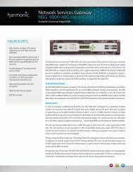
This guide describes the installation <strong>and</strong> startup instructions for the<br />
<strong>Narrowcast</strong> <strong>Services</strong> <strong>Gateway</strong> family, including the <strong>NSG</strong> <strong>9116</strong>, <strong>9112</strong> <strong>and</strong><br />
9108. The <strong>NSG</strong> is a highly integrated digital video <strong>and</strong> data gateway<br />
between on-dem<strong>and</strong> content servers <strong>and</strong> their subscribers. Designed as<br />
a 1-RU chassis, the <strong>NSG</strong> family performs PID filtering, multiplexing,<br />
scrambling, QAM modulation, <strong>and</strong> RF upconversion for either sixteen,<br />
twelve or eight transport streams simultaneously. It can supply video <strong>and</strong><br />
other on-dem<strong>and</strong> multimedia services to large numbers of subscribers.<br />
The <strong>NSG</strong> accepts digital MPEG input through a Gigabit Ethernet (GbE)<br />
port. The <strong>NSG</strong> directs multimedia to the different QAMs <strong>and</strong> upconverters<br />
to create the outgoing transport streams as QAM-RF output<br />
signals.<br />
Note: This guide uses the term <strong>NSG</strong> to refer to the <strong>NSG</strong> <strong>9116</strong>, <strong>9112</strong><br />
<strong>and</strong> 9108.<br />
Manual Organization<br />
This guide is organized as follows:<br />
■ Chapter 1, “Features <strong>and</strong> Specifications,” introduces features of the<br />
<strong>NSG</strong>.<br />
■ Chapter 2, “Cabling <strong>and</strong> Configuration,” describes how to cable <strong>and</strong><br />
configure the <strong>NSG</strong>.<br />
■ Chapter 3, “Troubleshooting,” describes how to resolve <strong>NSG</strong><br />
hardware alarms.<br />
■ Appendix A, “Fuse Replacement,” contains service information that<br />
explains how to replace the fuse in the <strong>NSG</strong>.
viii Manual Organization Preface<br />
■ Appendix B, “Wiring the –48 VDC Power Supply,” describes how to<br />
connect the optional –VDC power source.<br />
■ Appendix C, “Advanced Fiber Optic Connections,” describes<br />
advanced fiber optic cabling schemes including cascading <strong>and</strong> using<br />
a DWDM in your network.<br />
■ Appendix D, “Customer Support Information,” provides Customer<br />
Support contact information.<br />
■ , “Glossary,” lists commonly used industry-wide terms as well as terms<br />
used in this guide.<br />
Conventions<br />
This guide uses the following notational conventions:<br />
Convention Description<br />
Courier font regular System messages, syntax statements, or<br />
comm<strong>and</strong> examples.<br />
Courier font bold Comm<strong>and</strong>s that you are instructed to enter.<br />
italic font For emphasis or comm<strong>and</strong> variables.<br />
[italic font] In syntax statements, items inside brackets are<br />
optional.<br />
Caution: Indicates a situation that might impair data.<br />
Note: Highlights important information.<br />
Tip: Provides time-saving or informative suggestions<br />
about using the product.<br />
Warning: Indicates a situation that causes damage to the<br />
system or might harm a person.
Introduction<br />
<strong>NSG</strong> 9100<br />
Chapter 1<br />
Features <strong>and</strong> Specifications<br />
<strong>Harmonic</strong>'s <strong>NSG</strong> 9100 product line includes the <strong>NSG</strong> <strong>9116</strong>, <strong>9112</strong> <strong>and</strong><br />
9108. The <strong>NSG</strong> provides digital video remultiplexing, scrambling, QAM<br />
modulation, <strong>and</strong> RF upconversion for video on dem<strong>and</strong> networks. The<br />
<strong>NSG</strong> accepts digital MPEG input through 2 x GbE ports configured to<br />
work as redundant GbE channels or as independent channels that<br />
simultaneously receive different GbE feeds. The <strong>NSG</strong> delivers up to<br />
sixteen transport streams through RF output ports implementing dual<br />
upconverter technology.<br />
The following table provides a general description of the <strong>NSG</strong> 9100<br />
product line:
2 Introduction CHAPTER 1<br />
<strong>NSG</strong> Input Output<br />
<strong>9116</strong> 2 x GbE ports with two<br />
modes of operation:<br />
■ two redundant<br />
channels<br />
■ two independent ports<br />
receiving different<br />
feeds<br />
<strong>9112</strong> 2 x GbE ports with two<br />
modes of operation:<br />
■ two redundant<br />
channels<br />
■ two independent ports<br />
receiving different<br />
feeds<br />
9108 1 x GbE port with two<br />
redundant channels<br />
Note: The <strong>NSG</strong> comes with either an AC power supply or –48 VDC<br />
power supply. All types of <strong>NSG</strong>s are intended to be installed in<br />
restricted access locations.<br />
Management Interfaces<br />
8 x RF ports carrying 16 x<br />
QAM transport streams<br />
6x RF ports carrying 12 x<br />
QAM transport streams<br />
4x RF ports carrying 8 x<br />
QAM transport streams<br />
<strong>Harmonic</strong> offers several methods for configuring <strong>NSG</strong> devices <strong>and</strong><br />
monitoring their status. All management interfaces listed below connect<br />
to the <strong>NSG</strong> over LAN, via its ETH1 Ethernet port.<br />
Caution: <strong>Harmonic</strong> strongly recommends using an Ethernet network<br />
that is isolated from any other networks or subnets at your site for<br />
management of the <strong>NSG</strong>s.It ensures adequate security, <strong>and</strong> prevents<br />
possible disturbances to the normal operation of <strong>NSG</strong> devices due to<br />
uncontrolled network activity.
Features <strong>and</strong> Specifications Introduction<br />
The table below lists the available management interfaces according to<br />
the management purpose for which they are designed:<br />
Purpose Recommended Tool<br />
Preliminary<br />
configuration <strong>and</strong><br />
monitoring of a<br />
single <strong>NSG</strong> device<br />
Configuration <strong>and</strong><br />
monitoring of a<br />
single <strong>NSG</strong> device<br />
Control Panel<br />
The <strong>NSG</strong> control panel is comprised of a display area <strong>and</strong><br />
key pad located on the front panel of the <strong>NSG</strong>. The control<br />
panel is active once the <strong>NSG</strong> boots up <strong>and</strong> provides<br />
means for preliminary configuration of a single <strong>NSG</strong><br />
device. It also allows you to monitor the <strong>NSG</strong>'s status, view<br />
its alarms (if present), <strong>and</strong> troubleshoot them. For details<br />
on accessing the web client, please see the <strong>NSG</strong> Web<br />
Client..<br />
The <strong>NSG</strong> web client is an on-board web-based user<br />
interface, that is an integral part of the <strong>NSG</strong> firmware. The<br />
web client is accessible through Microsoft Internet<br />
Explorer, <strong>and</strong> provides means for configuring a single<br />
<strong>NSG</strong> device. It also allows the user to monitor the <strong>NSG</strong>'s<br />
status, view its alarms (if present), <strong>and</strong> troubleshoot them.<br />
For details on accessing the web client, see Chapter 2,<br />
“Connecting Power,” .<br />
3
4 Introduction CHAPTER 1<br />
Purpose Recommended Tool<br />
Configuration of<br />
multiple <strong>NSG</strong><br />
devices<br />
Status <strong>and</strong> Alarm<br />
Monitoring of<br />
multiple <strong>NSG</strong><br />
devices<br />
Note: The MCT database is not automatically updated when an <strong>NSG</strong> is<br />
configured using NMX or the web client. To update the MCT database,<br />
select the <strong>NSG</strong> <strong>and</strong> execute the following comm<strong>and</strong> from the MCT<br />
Actions menu: Actions > Synchronize > Get from Target.<br />
GbE Channel Redundancy<br />
MCT (Mass Configuration Tool).<br />
The MCT is a spreadsheet-oriented system designed to<br />
configure multiple <strong>NSG</strong>s simultaneously. MCT is<br />
recommended for large-scale <strong>NSG</strong> deployments. Besides<br />
simultaneous configuration of large number of <strong>NSG</strong><br />
devices, it also allows users to perform firmware upgrade<br />
for multiple <strong>NSG</strong>s. MCT is sold separately - please contact<br />
<strong>Harmonic</strong> Customer Support for more details.<br />
Note: MCT is not automatically updated when an <strong>NSG</strong> is<br />
configured through the web client. Using the web client<br />
for configuring individual <strong>NSG</strong>s in an MCT-based site is<br />
not recommended. If the web client is used, care should<br />
be taken to update MCT with the changed configuration.<br />
For details on synchronizing MCT with <strong>NSG</strong> devices,<br />
please refer to the MCT online help.<br />
<strong>Harmonic</strong> NMX / 3rd party SNMP monitoring.<br />
NMX (<strong>Harmonic</strong>'s Digital Service Manager) may be used<br />
for monitoring general status <strong>and</strong> alarms of multiple <strong>NSG</strong><br />
devices. A single NMX manager may be used to monitor<br />
several hundreds <strong>NSG</strong> devices, located in several different<br />
sites.<br />
In addition, <strong>NSG</strong> may report its status <strong>and</strong> alarms via<br />
st<strong>and</strong>ard SNMP. Any st<strong>and</strong>ard-based SNMP monitoring<br />
system may be used for monitoring the status of multiple<br />
<strong>NSG</strong> devices. This includes off-the-shelf systems such as<br />
HP OpenView, or custom-made systems. For further<br />
details on implementing SNMP monitoring for <strong>NSG</strong><br />
devices, please contact <strong>Harmonic</strong> Customer Support.<br />
The <strong>NSG</strong> family supports GbE redundancy to provide the network with<br />
fault-tolerant design. The objective of the redundant channel is to<br />
eliminate or diminish any service interruptions when an active GbE
Features <strong>and</strong> Specifications Features <strong>and</strong> Specifications by <strong>NSG</strong> Model<br />
channel fails. <strong>NSG</strong>s with the redundancy feature do not have a primary<br />
<strong>and</strong> secondary channel but rather have two symmetrical GbE channels.<br />
Therefore, when a redundant channel is activated it will continue to<br />
operate <strong>and</strong> will not revert back to the previously active channel when<br />
that channel recovers.<br />
Redundancy for both GbE1 <strong>and</strong> GbE2 is activated by one of two <strong>NSG</strong><br />
alarms:<br />
■ Chapter 3, “GbE X Link down,”<br />
■ Chapter 3, “GbE X SFP not mounted,”<br />
Note: Automatic GbE channel redundancy is unavailable in Switching<br />
mode. In this mode the ports are configured to work independently <strong>and</strong><br />
to receive different GbE feeds.<br />
Note: Automatic GbE channel redundancy is unavailable when using<br />
copper SFP. The redundant channel is activated only when the alarm<br />
SFP not mounted appears. The SFP does not trigger the GbE link down<br />
alarm.<br />
<strong>NSG</strong> Backup Capability<br />
The <strong>NSG</strong> includes a Non Volatile RAM (NVRAM) that is also powered by a<br />
lithium battery. The NVRAM allows configuration backup <strong>and</strong> maintains<br />
the <strong>NSG</strong> time.<br />
Caution: Risk of explosion if battery is replaced by an incorrect<br />
type. Dispose of used batteries according to the instructions.<br />
Features <strong>and</strong> Specifications by <strong>NSG</strong> Model<br />
The following table describes the features of the <strong>NSG</strong> 9100.<br />
5
6 Features <strong>and</strong> Specifications by <strong>NSG</strong> Model CHAPTER 1<br />
Feature Description<br />
Chassis 1-RU, mounts in Electronic Industries<br />
Association (EIA) st<strong>and</strong>ard rack<br />
2 x GbE input ports ■ Provide two redundant GbE channels, or<br />
two independent ports receiving<br />
simultaneously different feeds<br />
■ Max. allowed PCR jitter 10 msec (peak to<br />
peak)<br />
■ Payload of up to 800 Mbps (up to 256<br />
services)<br />
■ Max. Ethernet traffic (payload + pass<br />
through traffic) 1000 Mbps<br />
16, 12 or 8 x QAM<br />
modulators<br />
■ QAM Mode:<br />
■ DVB (Annex A): 8 MHz<br />
■ ITU-T (Annex B J.83): 6 MHz<br />
■ ITU-T (Annex-C - Japan), 6 MHz<br />
■ QAM Constellations:<br />
■ Annex-A: 16, 32, 64, 128, 256<br />
■ Annex-B: 64,256<br />
■ Annex-C: 16, 32, 64, 128, 256<br />
Maximum output bit rate ■ DVB: 408 Mbps (51.2 Mbps x 16)<br />
■ ITU-T: 310.4 Mbps (38.8 Mbps x 16)<br />
8, 6 or 4x RF outputs ■ Each port carries two QAM channels,<br />
combined <strong>and</strong> upconverted into two<br />
adjacent RF channels<br />
■ Connector: F-type<br />
■ Recommended Cable: 75 Ohm, RG-6<br />
■ QAM / RF Specifications:<br />
■ see product specifications sheet<br />
1 x ASI monitoring port ASI monitoring port can be configured to<br />
output the same data as the RF output ports.<br />
The ASI Port can be configured to monitor all<br />
transports.<br />
Front panel LEDs Power, alarm, 2 input status, <strong>and</strong> 16, 12 <strong>and</strong> 8<br />
output status LEDs.
Features <strong>and</strong> Specifications Features <strong>and</strong> Specifications by <strong>NSG</strong> Model<br />
Feature Description<br />
Back panel LEDs Activity <strong>and</strong> alarm LED pairs for each GbE port<br />
(four LEDs in all).<br />
Dynamic extraction of<br />
input<br />
Filtering of GbE input<br />
services<br />
■ Dynamic detection of changes in services<br />
<strong>and</strong> PSI tables at the input<br />
■ Automatic reflection of input changes into<br />
the output stream within one second<br />
Data arriving to the <strong>NSG</strong> input GbE ports is<br />
filtered based on routing information<br />
communicated by the video server<br />
PID remapping PIDs of incoming services are remapped in<br />
one of two ways (user-configurable):<br />
■ Paradigm<br />
■ R<strong>and</strong>om<br />
Motorola pre-encryption<br />
support<br />
10Base-T/100Base-T<br />
Ethernet ports<br />
Accepts Motorola pre-encrypted content<br />
Two independent Ethernet ports, typically<br />
used for management (ETH1) <strong>and</strong> (ETH2)<br />
SNMP support Built-in SNMP agent communicates device<br />
status via SNMP traps<br />
PSI generation for each<br />
output<br />
Generation of PSI (PAT <strong>and</strong> PMT) for each<br />
individual output stream<br />
Monitoring <strong>and</strong> control Configuration, control, <strong>and</strong> monitoring by:<br />
■ <strong>Harmonic</strong> NMX Digital Service Manager<br />
■ <strong>NSG</strong> web client accessed using Internet<br />
Explorer 5.0 to 6.0<br />
■ Massive Configuration Tool (MCT)<br />
■ Control Panel<br />
7
8 Features <strong>and</strong> Specifications by <strong>NSG</strong> Model CHAPTER 1<br />
Environmental Specifications<br />
The following table lists the environmental specifications for the <strong>NSG</strong>.<br />
Dimensions<br />
Parameter Description<br />
Height 4.4 cm (1.73 in)<br />
Width 44 cm (17.3 in)<br />
Depth 62.5 cm (24.6 in)<br />
Operating temperature 0 to 50 °C (32 to 122 °F)<br />
Storage temperature –40 to 70 °C (–40 to 158 °F)<br />
Relative humidity Maximum 85% non-condensing<br />
Ventilation If units are installed in a closed rack, the rack<br />
must be ventilated to ensure proper cooling of<br />
the units. Ventilation rate must be:<br />
At least 1.0 cubic meter per minute (35 cubic<br />
feet per minute) per <strong>NSG</strong> unit.
Features <strong>and</strong> Specifications Stream Processing Overview<br />
Stream Processing Overview<br />
The <strong>NSG</strong> accepts a GbE input, <strong>and</strong> outputs analog RF. The following<br />
diagram shows the flow of data through the GbE channel.<br />
Note: The diagram shows the maximum output of 8 RF. <strong>NSG</strong> <strong>9112</strong> <strong>and</strong><br />
9108 output 6 or 4 analog RF respectively.<br />
9
10 <strong>NSG</strong> Front Panel CHAPTER 1<br />
<strong>NSG</strong> Front Panel<br />
The front panel of the <strong>NSG</strong> contains the following:<br />
■ RS-232 connector - enables to connect the <strong>NSG</strong> to another PC.<br />
■ QAM Output LEDs - up to sixteen LEDs for monitoring QAM output<br />
ports. The number of LEDs varies according to the number of QAM<br />
output ports. In <strong>NSG</strong> <strong>9116</strong> there are sixteen LEDs, in <strong>9112</strong> twelve<br />
<strong>and</strong> in <strong>NSG</strong> 9108 there are eight LEDs.<br />
■ Power, Alarm, Input 1 <strong>and</strong> Input 2 LEDS - enables to monitor the<br />
status of the <strong>NSG</strong> power, alarm <strong>and</strong> input ports.<br />
■ Control panel- comprised of a display area <strong>and</strong> a keypad. The control<br />
panel enables preliminary configuration <strong>and</strong> monitoring of the <strong>NSG</strong>.<br />
The following figure illustrates the front panel of the <strong>NSG</strong> 9100:<br />
Control Panel<br />
The control panel allows you to monitor <strong>and</strong> configure the <strong>NSG</strong>. You can<br />
start using the control panel once the <strong>NSG</strong> boots up <strong>and</strong> the Power up<br />
screen appears in the control panel display.
Features <strong>and</strong> Specifications <strong>NSG</strong> Front Panel<br />
Front Panel LEDs<br />
The following table describes the front panel LEDs, from left to right.<br />
LED Color Description<br />
Output Green/Red/<br />
Orange<br />
ON (Green) - Indicates the output port is<br />
properly configured <strong>and</strong> has at least one<br />
service.<br />
ON (Red) - Indicates an output alarm has been<br />
activated.<br />
ON (Orange) - Indicates an output warning has<br />
been activated.<br />
ON (Green blinking) - Indicates the 'Identify unit'<br />
button has been selected.<br />
OFF - Indicates the output port has no service<br />
or is disabled.<br />
Power Green ON - Indicates that <strong>NSG</strong> is powered on.<br />
OFF - Indicates that <strong>NSG</strong> is powered off.<br />
Alarm Red/Orange ON (Red) - Indicates an alarm has been<br />
activated in the device.<br />
ON (Orange) - Indicates a warning has been<br />
activated in the device.<br />
Refer to Chapter 3, “Troubleshooting,” for<br />
further details.<br />
OFF - Indicates no alarm activated.<br />
Input Green/Red/<br />
Orange<br />
The first LED shows the status of GbE channel<br />
1, <strong>and</strong> the second LED shows the status of GbE<br />
channel 2.<br />
ON (Green) - Indicates the input port is enabled<br />
<strong>and</strong> has a valid GbE signal.<br />
ON (Red) - Indicates an input related alarm has<br />
been activated. The activated LED indicates the<br />
specific port with the alarm.<br />
ON (Orange) - Indicates an input related<br />
warning has been activated. The activated LED<br />
indicates the specific port with the warning.<br />
ON (Green blinking) - Indicates the 'Identify unit'<br />
button has been selected.<br />
OFF - Indicates the input port is disabled.<br />
11
12 Back Panel CHAPTER 1<br />
EIA-232 Serial Port<br />
Air Inlets<br />
Back Panel<br />
The EIA-232 serial port may be used to configure the Ethernet port IP<br />
addresses. You can use the serial port for monitoring <strong>and</strong> manual<br />
maintenance operations. The EIA-232 serial port has a female DB-9 D-typ<br />
connector.<br />
Air inlets are located along the lower, upper <strong>and</strong> right middle parts of the<br />
<strong>NSG</strong> front panel. The air inlets are designed to provide maximum air flow.<br />
This section describes the back panel of the <strong>NSG</strong>. The back panel of the<br />
<strong>NSG</strong> <strong>9116</strong>, <strong>9112</strong> <strong>and</strong> 9108 differ in the number of RF output ports only.<br />
The <strong>NSG</strong> <strong>9116</strong> has eight RF output ports, as the following figure<br />
illustrates. <strong>NSG</strong> <strong>9112</strong> has six output ports <strong>and</strong> <strong>NSG</strong> 9108 has four output<br />
ports.<br />
The <strong>NSG</strong> back panel has one ASI output port <strong>and</strong> two Gigabyte Ethernet<br />
(GbE) receptacles for Small Form Factor Pluggable (SFP) transceivers.
Features <strong>and</strong> Specifications Back Panel<br />
Note: The cabling of the JTAG connector of the service port shall use<br />
min. 18AGW copper UL listed wiring.<br />
Power Supply<br />
AC Power Supply<br />
The power supply supports 110 <strong>and</strong> 230 VAC, <strong>and</strong> automatically senses<br />
the required voltage. A fuse is located inside the power socket <strong>and</strong> a<br />
spare is located inside the adjacent compartment. For information about<br />
replacing the fuse, see Appendix A, “Fuse Replacement,” .<br />
See “Connecting the AC Power Cable” on page 23 for instructions to<br />
connect the power supply.<br />
The following table lists the power supply specifications.<br />
Parameter Specification<br />
Input voltage 100–240 VAC<br />
Line frequency 60–50 Hz<br />
Typical power<br />
consumption<br />
–48 VDC Power Supply<br />
154 W<br />
If your <strong>NSG</strong> has the optional –48 VDC power supply, the st<strong>and</strong>ard AC<br />
power connector is replaced by a panel with a 3-pin male connector for<br />
–48 VDC. This power supply does not have a fuse.<br />
See “Connecting Power” on page 23 for instructions to wire the power<br />
supply.<br />
The <strong>NSG</strong>’s electrical rating for the -48VDC type is as follows:<br />
13
14 Back Panel CHAPTER 1<br />
Note: Consideration should be given to the connection of the<br />
equipment to the supply circuit <strong>and</strong> the effect that overloading of<br />
circuits might have on overcurrent protection <strong>and</strong> supply wiring.<br />
Appropriate consideration of equipment nameplate ratings should be<br />
used when addressing this concern.<br />
Ethernet Ports<br />
The <strong>NSG</strong> back panel has two Ethernet ports to allow connection to two<br />
Ethernet networks. See “Establishing Ethernet Connection” on page 22<br />
for instructions to configure IP addresses for the Ethernet ports.<br />
Use UTP cables with an RJ-45 connector to connect the <strong>NSG</strong> to a hub or<br />
router for the management networks.<br />
GbE Input Port<br />
Parameter Specification<br />
Voltage 48/60 VDC<br />
Note: The device can still operate with input<br />
voltage ranging from 36 to 75 VDC.<br />
Max. operating current 4 amps<br />
The <strong>NSG</strong> back panel includes two SFP module receptacles labeled GbE 1<br />
<strong>and</strong> 2 for GbE input.
Features <strong>and</strong> Specifications Back Panel<br />
The following table lists the GbE port specifications.<br />
Parameter Specification<br />
Connector Two receptacles for SFP connectors.<br />
Maximum input bit rate ■ Line rate up to 1000 Mbps.<br />
■ Processing up to 800 Mbps of MPEG data<br />
(up to 256 services).<br />
■ Cascading up to 1000 Mbps of traffic.<br />
The back panel of the <strong>NSG</strong> features two LEDs for each GbE port. The<br />
following table describes the LEDs:<br />
LED Color Description<br />
Activity Green ■ Illuminates when a live fiber is<br />
connected to the port <strong>and</strong> a network<br />
link is detected.<br />
■ Blinks when real traffic flows through<br />
the link.<br />
Alarm Orange Indicates an error in the GbE port.<br />
15
16 Back Panel CHAPTER 1<br />
SFP Module<br />
The SFP module converts optical data into electrical data <strong>and</strong> vice versa.<br />
The following figure illustrates an SFP module:<br />
Warning: Class I laser product.<br />
You can use either of the following types of SFP depending on the<br />
cable/fiber type you are using. You can purchase SFPs separately from<br />
the <strong>NSG</strong> either from <strong>Harmonic</strong> or other sources. In this case it is strongly<br />
recommended to purchase SFP models qualified by <strong>Harmonic</strong>:<br />
Fiber/Cable<br />
Type<br />
Connector Type Wave Length<br />
Qualified SFP<br />
Make/Model<br />
Multi-mode fiber 2xLC 850 nm Finisar FTRJ-<br />
8519-7D<br />
Single-mode<br />
fiber<br />
UTP Cat-5<br />
copper<br />
2xLC 1310 nm Finisar FTRJ-<br />
1310-3<br />
1xRJ-45 N/A ____________<br />
Note: When using an SFP with a copper cable, enable the Auto<br />
Negotiate <strong>and</strong> Last in Chain options via the Web client. Cascading is<br />
unavailable <strong>and</strong> the automatic channel redundancy is activated only<br />
when the alarm SFP not mounted appears. The copper SFP does not<br />
trigger the GbE link down alarm.
Features <strong>and</strong> Specifications Back Panel<br />
<strong>NSG</strong> Output Ports<br />
RF Ports<br />
The <strong>NSG</strong> back panel has up to eight RF ports, numbered 1–8. Each port<br />
outputs two channels.<br />
Use RG-6 coaxial cables cable with F-type connectors to connect the RF<br />
ports to the output devices. See“Connecting the QAM-RF Output Cables”<br />
on page 21 for more information.<br />
The following table provides the RF port specifications:<br />
ASI Output Port for Monitoring<br />
The <strong>NSG</strong> duplicates one transport stream to one ASI output port<br />
designed for monitoring purposes, applicable to both ASI <strong>and</strong> GbE data.<br />
Use this port to connect to devices that accept ASI input, such as an<br />
MPEG analyzer.<br />
What’s Next...<br />
Parameter Description<br />
Connector Male F connector<br />
Cable RG-6<br />
Output frequency 53-868 MHz<br />
The next step is to unpack <strong>and</strong> cable the <strong>NSG</strong>, as described in the<br />
following chapter.<br />
17
18 Back Panel CHAPTER 1
Chapter 2<br />
Cabling <strong>and</strong> Configuration<br />
This chapter describes how to cable <strong>and</strong> set preliminary configuration to<br />
the <strong>NSG</strong>. The various sections of this chapter are arranged according to<br />
the order of actions you need to perform in order to start using the <strong>NSG</strong><br />
unit:<br />
■ Unpacking the <strong>NSG</strong><br />
■ Cabling the <strong>NSG</strong><br />
■ Connecting Power<br />
■ Setting Preliminary configuration to the <strong>NSG</strong><br />
■ Starting the <strong>NSG</strong> Web Client<br />
Unpacking the <strong>NSG</strong><br />
Installing the <strong>NSG</strong><br />
The <strong>NSG</strong> comes in a specially designed shipping container that ensures<br />
its safety during shipping <strong>and</strong> h<strong>and</strong>ling. To avoid damaging the <strong>NSG</strong>,<br />
unpack it carefully.<br />
Each <strong>NSG</strong> unit consists of a1-RU chassis installed in a st<strong>and</strong>ard 19-inch<br />
computer rack.<br />
Note: Mounting the <strong>NSG</strong> unit in the rack should be such that a<br />
hazardous condition is not achieved due to uneven mechanical loading.<br />
To install the <strong>NSG</strong> unit:<br />
1. Place the 1-RU chassis on the computer rack.
20 Cabling the <strong>NSG</strong> CHAPTER 2<br />
Cabling the <strong>NSG</strong><br />
2. Attach the chassis to the computer rack as follows:<br />
Front - Fasten the front holders to the rack.<br />
Back - Fasten the L-shaped holders to the rack.<br />
Connecting cables to the <strong>NSG</strong> is straightforward. The <strong>NSG</strong> GbE input<br />
ports, QAM-RF or ASI output ports, <strong>and</strong> Ethernet ports are clearly marked<br />
on the <strong>NSG</strong> back panel. See “Back Panel” on page 12 for placement.<br />
Connecting the GbE Port<br />
To connect the GbE port to the Content server use either of the<br />
following:<br />
■ Multimode or single-mode optic fiber with an LC connector. The LC<br />
connector plugs into an SFP receptacle <strong>and</strong> accommodates two<br />
fibers, one for transmission <strong>and</strong> the other for reception.<br />
■ Copper cable with an RJ-45 connector. The RJ-45 connector plugs<br />
into a copper SFP receptacle.<br />
The <strong>NSG</strong> supports two SFP modules for channel redundancy. However,<br />
when using copper SFP, automatic channel redundancy is activated only<br />
when unplugging the SFP from the current active port.<br />
To connect the fiber/cable to the <strong>NSG</strong>:<br />
1. Insert the SFP modules into the receptacles labeled GbE 1 <strong>and</strong> GbE 2<br />
at the back of the <strong>NSG</strong>.<br />
2. Insert the LC/RJ-45 plugs into the SFP module.<br />
3. Connect the <strong>NSG</strong> to a switch or other <strong>NSG</strong> as appropriate for your<br />
network configuration.<br />
The following figures show a basic connection between an <strong>NSG</strong> <strong>and</strong> a<br />
switch. The first figure refers to a connection with optic fibers <strong>and</strong> the<br />
second with copper cables:
Cabling <strong>and</strong> Configuration Cabling the <strong>NSG</strong><br />
The <strong>NSG</strong> also supports advanced fiber optic cabling schemes such as<br />
cascading, redundancy, IP Switching <strong>and</strong> including a DWDM in your <strong>NSG</strong><br />
network. See Appendix C, “Advanced Fiber Optic Connections,” for<br />
instructions.<br />
Connecting the QAM-RF Output Cables<br />
The <strong>NSG</strong> has up to eight RF output ports, labeled RF OUT <strong>and</strong> numbered<br />
1– 8, which implement the dual upconverter technology. Each port<br />
delivers two RF channels.<br />
To connect the RF Cables:<br />
➭ Use RG-6 coaxial cables equipped with F-type connectors to connect<br />
the outgoing ports to your output equipment according to your<br />
network schema.<br />
21
22 Cabling the <strong>NSG</strong> CHAPTER 2<br />
Connecting the ASI Monitoring Port Cables<br />
The ASI output port for the <strong>NSG</strong> provides a method to monitor the<br />
device’s output data.<br />
To connect the ASI output cable:<br />
➭ Connect the ASI cable with a BNC connector from the ASI output port<br />
on the <strong>NSG</strong> back panel to a device such as an MPEG analyzer.<br />
Connecting the Ethernet Cables<br />
The Ethernet ports, labeled ETH1 <strong>and</strong> ETH2, provide access to two<br />
independent networks.<br />
To connect the Ethernet cables:<br />
➭ Connect an Ethernet cable with RJ-45 connectors from the ETH1 port<br />
on the <strong>NSG</strong> to your management network hub or switch.<br />
Establishing Ethernet Connection<br />
Because the <strong>NSG</strong> is configured <strong>and</strong> controlled by a remote management<br />
system, you must set the IP addresses of the Ethernet ports located on<br />
the back panel of the <strong>NSG</strong>. To set <strong>NSG</strong> IP address, use the control panel<br />
located on the front panel of the <strong>NSG</strong>. For further information, refer to<br />
“Preliminary Configuration of the <strong>NSG</strong>” on page 25.<br />
You may also use other management interfaces. For further information,<br />
refer to the web client online help or, in case of a number of <strong>NSG</strong><br />
devices, use the MCT (Mass Configuration Tool) <strong>and</strong> refer to its online<br />
help.<br />
Note: The <strong>NSG</strong> requires a user name <strong>and</strong> password to log in to all<br />
management interfaces, including the serial communications console,<br />
web client <strong>and</strong> FTP. You must contact <strong>Harmonic</strong> Customer Support to<br />
obtain the user name <strong>and</strong> password before you can proceed with the<br />
following configuration. See Appendix D, “Customer Support<br />
Information,” for Customer Support contact information.
Cabling <strong>and</strong> Configuration Connecting Power<br />
Connecting Power<br />
The <strong>NSG</strong> comes with either an AC power supply or a –48 VDC power<br />
supply. Follow the instructions appropriate to your power supply.<br />
Note: Reliable earthing of rack-mounted equipment should be<br />
maintained.Particular attention should be given to supply connections<br />
other than direct connections to the branch circuit.<br />
Connecting the AC Power Cable<br />
If your <strong>NSG</strong> has the AC power line cord, connect the power cord to the<br />
power plug on the <strong>NSG</strong> back panel, <strong>and</strong> connect the power cord to the<br />
power outlet.<br />
The power supply automatically senses the input voltage.<br />
Connecting the –48 VDC Power Supply<br />
If your <strong>NSG</strong> has the optional –48 VDC power supply, see<br />
Appendix B, “Wiring the –48 VDC Power Supply,” for instructions to wire<br />
the power supply.<br />
When you connect the <strong>NSG</strong> to the power supply, the boot up procedure<br />
starts. During boot up the following messages appear in the control panel<br />
display:<br />
Power up - indicates the beginning of the procedure.<br />
Booting... - indicates the booting stage.<br />
Loading... - indicates that the unit loads the application.<br />
Once boot up is complete the Power Up screen appears in the control<br />
panel display <strong>and</strong> you may start configuring the <strong>NSG</strong>. The Power Up<br />
screen shows the company’s name, type of <strong>NSG</strong> <strong>and</strong> a default IP address.<br />
23
24 Connecting Power CHAPTER 2<br />
What’s Next...<br />
The next step is to set preliminary configuration to the <strong>NSG</strong>, as described<br />
in the following section.
Cabling <strong>and</strong> Configuration Preliminary Configuration of the <strong>NSG</strong><br />
Preliminary Configuration of the <strong>NSG</strong><br />
You can set preliminary configuration <strong>and</strong> control the <strong>NSG</strong> unit via its<br />
front panel. The front panel includes a control panel comprised of a<br />
Liquid Crystal Display (LCD) <strong>and</strong> six buttons as the following figure shows:<br />
Control Panel Display<br />
The 2-line, 16-character control panel display shows the screens, subscreens,<br />
sub-screen options, error messages, warnings <strong>and</strong> alarms. The<br />
control panel display is comprised of two lines:<br />
Line 1 - displays the name of the current screen/sub-screen or selected<br />
option.<br />
Line 2 - displays the parameter value <strong>and</strong> all editing tasks are performed<br />
in this line. In editing mode the cursor is blinking to indicate the selected<br />
character.<br />
25
26 Preliminary Configuration of the <strong>NSG</strong> CHAPTER 2<br />
Control Panel Screen Concept<br />
The control panel screens are organized in a hierarchical fashion to<br />
indicate that a main screen contains sub-screens <strong>and</strong> sub-screen<br />
options. You may access a sub-screen only via its main screen. The<br />
available main screens are as follows:<br />
Power Up screen - A main screen that appears as soon as the <strong>NSG</strong><br />
boots up <strong>and</strong> after a thirty minutes of inactivity. The screen shows the<br />
company’s name, <strong>NSG</strong> type <strong>and</strong> IP address.<br />
Network Config screen - allows to access sub-screens for ETH<br />
configuration. To return to this screen from any other screen, use the<br />
hotkey .<br />
Output screen - via its sub-menus you can view the status of each output<br />
port.<br />
Alarm screen - displays the last active alarm or warning. You can browse<br />
through the alarms to view them.<br />
Setup screen - via its sub-screens you can change the operation mode,<br />
edit the date <strong>and</strong> time, <strong>and</strong> reset the unit.<br />
Product Information screen - via its sub-screens you can view<br />
information about the <strong>NSG</strong>.<br />
The following table lists the main screens, their browsing sequence, subscreens<br />
<strong>and</strong> their options:<br />
Screen Browsing sequence Sub-screens Options<br />
Network Config Down - Output<br />
Up - Product Info.<br />
Output Down - Alarm<br />
Up - Network Config.<br />
screen<br />
Alarm Down - Setup<br />
Up - Output<br />
ETH1 IP<br />
ETH2 IP<br />
QAM#1 RF Freq. -<br />
QAM#16 FR Freq.<br />
Active alarms <strong>and</strong><br />
warnings<br />
Edit ETH1<br />
Edit ETH2
Cabling <strong>and</strong> Configuration Preliminary Configuration of the <strong>NSG</strong><br />
Screen Browsing sequence Sub-screens Options<br />
Setup Down - Product Info.<br />
Up - Alarm<br />
Product Info. Down - Network<br />
Config.<br />
Up - Setup<br />
Moving along the Screens<br />
Change operation<br />
mode<br />
Date <strong>and</strong> time<br />
Reset<br />
Unit Information<br />
Main board Info.<br />
Interface module<br />
Info.<br />
Software<br />
Information.<br />
Control panel<br />
hotkeys help.<br />
Edit date & time<br />
Switch modes<br />
Reset unit<br />
To move along the screens <strong>and</strong> sub-screens of the control panel, use the<br />
following buttons of the control panel keypad:<br />
Button Explanation<br />
Up & Down ■ browse through the screens/sub-screens.<br />
■ browse through sub-screen options.<br />
■ while editing, browse through numerical<br />
characters.<br />
Left & Right ■ while editing, move the cursor along the<br />
line.<br />
Enter ■ executes a selection of a screen/sub<br />
screen <strong>and</strong> of its available options.<br />
■ quits an editing session <strong>and</strong> applies<br />
changes.<br />
Esc ■ moves up a menu level.<br />
■ quits an editing session without applying<br />
changes.<br />
27
28 Preliminary Configuration of the <strong>NSG</strong> CHAPTER 2<br />
Using Hotkeys<br />
The hotkeys are a combination of up to three keys pressed<br />
simultaneously. The following table lists the available hotkeys <strong>and</strong><br />
describes their functionality:<br />
Hotkey Explanation<br />
Moves you to the Network Config screen.<br />
<br />
Press keys for 5 seconds<br />
at least<br />
Resets the unit.<br />
Adjusts the contrast of the display area.<br />
<br />
Press keys for 3 seconds<br />
at least<br />
Control Panel Operation Modes<br />
Moves to the Change Op Mode screen.<br />
While editing, clears the entry field <strong>and</strong> moves<br />
cursor to the bottom left.<br />
While editing, operates as a backspace.<br />
While editing, deletes entries.<br />
The control panel provides the user with two different access modes so<br />
as to impede unauthorized access:<br />
Monitor - the default mode that allows you to only view the configuration<br />
in the <strong>NSG</strong>.<br />
Configure - allows you to edit various parameters <strong>and</strong> to apply the<br />
changes. After thirty minutes of inactivity in this mode, the system<br />
switches automatically to Monitor mode. The Configure mode is<br />
controlled by a password to allow authorized users only to change the<br />
<strong>NSG</strong> settings. To obtain a password, refer to the document enclosed with<br />
the <strong>NSG</strong> unit.
Cabling <strong>and</strong> Configuration Preliminary Configuration of the <strong>NSG</strong><br />
To switch to Config mode:<br />
1. Navigate to the Setup screen, using the keys.<br />
2. Click Enter. The Operation Mode screen appears.<br />
3. Click . You are prompted to enter a password.<br />
4. Type in a password <strong>and</strong> click .<br />
The Change Op. Mode screen appears with a blinking cursor.<br />
5. To select the Config mode, click <strong>and</strong> then .<br />
The Operation Mode screen appears indicating the current operation<br />
mode. After thirty minutes of inactivity, the Configure mode changes<br />
automatically to the Monitor operation mode.<br />
Editing Tips<br />
You may edit parameters only in Config mode. If you are in Monitor<br />
mode <strong>and</strong> you are trying to edit parameters, you are prompted to enter a<br />
password <strong>and</strong> switch to Config mode.<br />
To start an editing session:<br />
■ Click Enter:<br />
The screen name changes to Edit (screen name).<br />
A blinking cursor appears on the first character of the second line of<br />
the screen.<br />
29
30 Preliminary Configuration of the <strong>NSG</strong> CHAPTER 2<br />
To quit an editing session <strong>and</strong> to apply changes:<br />
■ Click Enter:<br />
The screen name appears without the word “Edit”.<br />
The newly configured parameter appears in the second line of the<br />
screen.<br />
To quit an editing session without applying changes:<br />
■ Click .<br />
The screen name appears without the word “Edit”.<br />
Unchanged parameters appear in the second line of the screen.<br />
Configuring the <strong>NSG</strong><br />
Configure the <strong>NSG</strong> unit only after boot up. The control panel allows you<br />
to configure the following:<br />
■ IP address, subnet mask <strong>and</strong> gateway of ETH1.<br />
■ PHY configuration of ETH1.<br />
■ BOOTP for ETH1<br />
■ IP address <strong>and</strong> subnet mask of ETH2.<br />
■ PHY configuration of ETH2.<br />
■ Date <strong>and</strong> time.
Cabling <strong>and</strong> Configuration Preliminary Configuration of the <strong>NSG</strong><br />
Note: Any configuration requires a password. Call harmonic<br />
Customer Support to obtain a password. See Appendix D, “Customer<br />
Support Information”, for Customer Support contact information.<br />
Configuring Ethernet Ports<br />
Since the <strong>NSG</strong> is monitored <strong>and</strong> configured also by a remote<br />
management system, you must set the IP addresses of the Ethernet ports<br />
located on the back panel of the <strong>NSG</strong>.<br />
The <strong>NSG</strong> uses the Ethernet port labeled ETH1 to communicate with the<br />
management network. You may set the ETH1 IP address, subnet mask<br />
<strong>and</strong> default gateway. For ETH 2 you may configure only its IP address <strong>and</strong><br />
subnet mask.<br />
To configure the Ethernet ports, you may use either of the following tools:<br />
Configuration Tool Description<br />
MCT (Mass Configuration<br />
Tool<br />
Allows configuration of a number of <strong>NSG</strong><br />
devices.<br />
BOOTP Allows configuration of a number of <strong>NSG</strong><br />
devices, <strong>and</strong> requires a BOOTP setup in the<br />
network.<br />
Web client Allows remote individual configuration of an<br />
<strong>NSG</strong> unit.<br />
Control Panel Allows an individual configuration of an <strong>NSG</strong><br />
unit as explained below.<br />
The following sections describe how to configure individual <strong>NSG</strong> devices<br />
using the control panel of the unit.<br />
When you configure the network parameters of ETH ports via the control<br />
panel, the application checks the validity of the IP address <strong>and</strong> network<br />
group parameters.<br />
31
32 Preliminary Configuration of the <strong>NSG</strong> CHAPTER 2<br />
To configure ETH1 port:<br />
Once you are in Config mode, do the following:<br />
1. Navigate to the Network Config screen <strong>and</strong> click .<br />
The Ethernet Port 1 screen appears.<br />
2. Click . The ETH1 IP Address screen appears.<br />
3. Click . The Edit IP Address screen appears.<br />
4. Edit the IP address <strong>and</strong> click .<br />
The program checks whether you entered a valid IP address <strong>and</strong> only<br />
then applies changes. The Edit Ethernet Subnet Mask screen appears.<br />
5. Edit the subnet mask <strong>and</strong> click . The Edit Default GW screen<br />
appears.<br />
6. Edit the ETH gateway <strong>and</strong> click .<br />
The program checks whether you entered valid network parameters<br />
<strong>and</strong> only then applies changes. The ETH1 IP Address screen appears.<br />
If invalid network parameters are entered an error message appears.<br />
To configure ETH2 port:<br />
Note: If you are using the ETH2 port, you must configure its IP<br />
address on a different subnet than that of the Ethernet 1 port.<br />
Once you are in Config mode, do the following:<br />
1. Navigate to the Network Config screen <strong>and</strong> click .<br />
2. Click to open the Ethernet Port 2 screen.<br />
3. Click . The ETH2 IP Address screen appears.<br />
4. Click . The Edit IP Address screen appears.<br />
5. Enter the required IP address <strong>and</strong> click .<br />
The program checks whether you entered a valid IP address <strong>and</strong> only<br />
then applies changes. The Edit Subnet Mask screen appears.<br />
6. Enter the required subnet mask <strong>and</strong> click .
Cabling <strong>and</strong> Configuration Preliminary Configuration of the <strong>NSG</strong><br />
The program check whether the network group parameters are valid<br />
<strong>and</strong> only then applies the changes. The ETH2 IP Address screen<br />
appears.<br />
If invalid network parameters are entered an error message appears.<br />
PHY Configuration<br />
When configuring the physical layer (PHY), select either of the following<br />
options for each ETH ports:<br />
■ Auto Neg - a h<strong>and</strong>shake protocol used in Ethernet links. It must be<br />
selected if the other end of the Ethernet link also uses auto<br />
Negotiation. Selecting this protocol while communicating with a<br />
device that does not use it causes communication problems.<br />
■ 100 BT full - sets the speed to 100 BT <strong>and</strong> communication mode to<br />
full duplex.<br />
■ 10 BT full - sets the speed to 10 BT <strong>and</strong> communication mode to full<br />
duplex..<br />
■ 100 BT half - sets the speed to 100 BT <strong>and</strong> communication mode to<br />
half duplex.<br />
■ 10 BT half - sets the speed to 10 BT <strong>and</strong> communication mode to half<br />
duplex.<br />
To set PHY configuration for ETH1:<br />
Once you are in Config mode, do the following:<br />
1. Navigate to the Network Config screen <strong>and</strong> click .<br />
The Ethernet Port 1 screen appears.<br />
2. Click . The ETH1 IP Address screen appears.<br />
3. Click until the ETH1 PHY Config screen appears.<br />
4. Click . The Edit PHY Config screen appears.<br />
5. Using the keys select the required option.<br />
6. Click to apply changes <strong>and</strong> to return to the ETH1 PHY Config<br />
screen.<br />
33
34 Preliminary Configuration of the <strong>NSG</strong> CHAPTER 2<br />
To set PHY configuration for ETH2:<br />
Once you are in Config mode, do the following:<br />
1. Navigate to the Network Config screen <strong>and</strong> click .<br />
2. Navigate to the Ethernet Port 2 screen.<br />
3. Click . The ETH2 IP Address screen appears.<br />
4. Click until the ETH2 PHY Config screen appears.<br />
5. Click . The Edit ETH2 PHY Config screen appears.<br />
6. Using the keys select the required option.<br />
7. Click to apply changes <strong>and</strong> to return to the ETH2 PHY Config<br />
screen.<br />
Setting BOOTP<br />
You may select either of the following options for the ETH1 port:<br />
■ Enable - select if you have BOOTP setup in your network <strong>and</strong> also<br />
enter the required timeout. The required timeout is 10 seconds. If you<br />
enter 0 the unit will continue to send BOOTP requests for an unlimited<br />
time until it receives a reply.<br />
■ Disable - the default option. Select this option if you do not have<br />
BOOTP setup in your network.<br />
To enable/disable BOOTP:<br />
Once you are in Config mode, do the following:<br />
1. Navigate to the Network Config screen <strong>and</strong> click .<br />
The Ethernet Port 1 screen appears.<br />
2. Navigate to the ETH1 Port screen.<br />
3. Click . The ETH1 IP Address screen appears.<br />
4. Click until the ETH1 BOOTP screen appears.<br />
5. Click . The Edit BOOTP screen appears.<br />
6. Using the keys, select the required option.<br />
7. Click to apply changes <strong>and</strong> to return to the ETH1 BOOTP<br />
screen.
Cabling <strong>and</strong> Configuration Preliminary Configuration of the <strong>NSG</strong><br />
Configuring Date <strong>and</strong> Time<br />
You may set the date <strong>and</strong> time for the <strong>NSG</strong> using the control panel. The<br />
date <strong>and</strong> time are used in the generated reports.<br />
To change date <strong>and</strong> time:<br />
Once you are in Config mode, do the following:<br />
1. Navigate to the Setup screen <strong>and</strong> click .<br />
The Config Operation Mode screen appears.<br />
2. Click to open the Unit Date/Time screen.<br />
3. Click . The Edit Date/Time screen appears.<br />
4. To edit do the following:<br />
Move the blinking cursor along the line, using the keys.<br />
When the blinking cursor is on the character to be edited, browse to<br />
the required digit/month using the keys.<br />
5. To apply <strong>and</strong> to quit the editing mode, click .<br />
The Unit Date/Time screen appears with the newly updated date <strong>and</strong><br />
time.<br />
Reset the <strong>NSG</strong> Unit<br />
Via the control panel you may reset the <strong>NSG</strong> unit when required.<br />
To reset the <strong>NSG</strong> unit:<br />
Once your are in Config mode, do the following:<br />
1. Navigate to the Reset <strong>NSG</strong> sub-screen of the Setup main screen.<br />
2. Click <strong>and</strong> follow the instructions on the display area.<br />
Once boot up starts, the control panel displays the same messages as<br />
during power up. (For further details, refer to Connecting Power.) If<br />
BOOTP is enabled, an additional message appears indicating that the<br />
<strong>NSG</strong> connects to the BOOTP server.<br />
35
36 Preliminary Configuration of the <strong>NSG</strong> CHAPTER 2<br />
Monitoring the <strong>NSG</strong><br />
The control panel allows to monitor the following:<br />
■ Output ports: QAM port number, frequency, data rate <strong>and</strong><br />
constellation.<br />
■ Warnings <strong>and</strong> alarms.<br />
■ <strong>NSG</strong> MAC address.<br />
■ Product Information: <strong>NSG</strong> unit, main board, interface <strong>and</strong> software<br />
information.<br />
■ Control panel hotkeys.<br />
Monitoring Output Ports<br />
1. Navigate to the <strong>NSG</strong> Output screen, using the keys.<br />
2. Click .<br />
The QAM#1 screen appears.<br />
3. Do either of the following:<br />
To view data rate, click <strong>and</strong> to view also the constillation,<br />
click .<br />
Or<br />
To move to any other QAM, click the keys.<br />
4. To return to the main screen, click .<br />
Monitoring Alarms/Warnings<br />
You may browse through the alarms/warnings to view them. If an alarm/<br />
warning is cancelled, it disappears from the screen <strong>and</strong> the following<br />
alarm/warning is presented. If there are no alarms/warnings, the<br />
message “No alarms/Warn” appears.<br />
To monitor alarms/Warnings<br />
1. Navigate to the Alarm screen.<br />
The screen displays the number of alarms <strong>and</strong> warnings (from left to<br />
right)
Cabling <strong>and</strong> Configuration Preliminary Configuration of the <strong>NSG</strong><br />
2. Click .<br />
3. Browse through the alarms/warnings, using the keys.<br />
When a warning is displayed, the following sign appears at the top<br />
right corner of the LCD display: (W).<br />
Monitoring ETH ports MAC Address<br />
To monitor the ETH1 MAC Address<br />
1. Navigate to the Network Config screen <strong>and</strong> click .<br />
The Ethernet Port 1 screen appears.<br />
2. Click . The ETH1 IP Address screen appears.<br />
3. Click until the ETH1 MAC Address screen appears.<br />
To monitor the ETH2 MAC Address<br />
1. Navigate to the Network Config screen <strong>and</strong> click .<br />
The Ethernet Port 1 screen appears.<br />
2. Click to open the Ethernet Port 2 screen.<br />
3. Click until the ETH2 MAC Address screen appears.<br />
Monitoring Product Information<br />
The Product Information screen is related to the following sub-screens:<br />
■ Unit Information - allows to view unit type, unit version <strong>and</strong> unit S/N.<br />
■ Main Board Information - allows to view main board type, user <strong>and</strong><br />
S/N.<br />
■ Interface Information - allows to view interface type, version <strong>and</strong><br />
FPGA.<br />
■ Software Information - allows to view boot version, firmware version<br />
<strong>and</strong> main FPGA version.<br />
■ LCD Hotkeys Help - allows to view the various available hotkeys.<br />
37
38 Starting the Web Client CHAPTER 2<br />
To monitor product information:<br />
1. Navigate to the Product Information screen.<br />
2. Click .<br />
3. Browse through the sub-screens <strong>and</strong> their related options using the<br />
<strong>and</strong> keys.<br />
Monitoring Hotkeys<br />
1. Navigate to the Product Information screen.<br />
2. Click .<br />
3. Click until the Hotkey screen appears.<br />
4. Click .<br />
5. Click to view the hotkeys.<br />
What’s Next...<br />
Once the preliminary configuration is complete, do the following:<br />
■ Start the <strong>NSG</strong> web client to apply full configuration to the <strong>NSG</strong> unit.<br />
Starting the Web Client<br />
1. Start Microsoft Internet Explorer (IE) on a PC that resides on the same<br />
LAN as the <strong>NSG</strong>.<br />
2. In the address bar of the IE, type the <strong>NSG</strong>'s IP address. The <strong>NSG</strong> Web<br />
Client opens. Through the web client you may complete the<br />
configuration of the <strong>NSG</strong> <strong>and</strong> monitor its status.<br />
Note: For instructions on how to use the web client, you may invoke its<br />
integral Online Help located on the menu tree on the left side of the<br />
web client. Select the HELP link.
Cabling <strong>and</strong> Configuration Access Levels<br />
Access Levels<br />
The <strong>NSG</strong> 9100 family of products provides the user with two different<br />
access levels so as to impede unauthorized access. The two different<br />
access levels are monitor <strong>and</strong> configure, which can be entered using the<br />
correct Username <strong>and</strong> Password combination. The monitor access level<br />
allows you to only view the configuration in the <strong>NSG</strong> <strong>and</strong> the configure<br />
access level allows you to execute configuration parameters via the web<br />
client. Passwords for both access level may be changed through the web<br />
client. Refer to the <strong>NSG</strong> Online Help for further information on changing<br />
passwords.<br />
Entering the Monitor or Configure Access Level<br />
1. Launch Internet Explorer, <strong>and</strong> connect to the URL of the <strong>NSG</strong> e.g<br />
http://192.168.20.231.<br />
2. A login window pops up requesting user name <strong>and</strong> password.<br />
3. Enter in the User Name monitor or configure as appropriate.<br />
4. Enter in the Password monitor (for the monitor User Name) or<br />
configure (for the configure User Name) as appropriate.<br />
5. Select OK.<br />
You are now in the monitor or configure access level where you can view<br />
the <strong>NSG</strong> configuration only.<br />
39
40 Upgrading the Firmware CHAPTER 2<br />
Upgrading the Firmware<br />
The <strong>NSG</strong> ships with firmware <strong>and</strong> the web client installed. However,<br />
<strong>Harmonic</strong> periodically releases firmware updates. To find out if the<br />
provided firmware meets your needs or must be updated, contact<br />
<strong>Harmonic</strong> Technical Support.<br />
To upgrade a number of <strong>NSG</strong> devices use the MCT (<strong>NSG</strong> Mass<br />
Configuration Tool). Refer to the MCT Online Help for details.<br />
You can also upgrade individual <strong>NSG</strong> devices manually, as described in<br />
the following section.<br />
Updating the Firmware<br />
Before starting the upgrade process, verify the following:<br />
■ There is a BOOTP <strong>and</strong> TFTP setup in your network.<br />
■ You set an IP address to the <strong>NSG</strong> unit.<br />
■ You obtained the new <strong>NSG</strong> firmware provided by <strong>Harmonic</strong> Technical<br />
Support. Firmware may be provided via the <strong>NSG</strong> release CD or<br />
downloaded from the <strong>Harmonic</strong> FTP site.<br />
To upgrade the firmware, do the following:<br />
1. Copy the new firmware file to a directory accessible by the TFTP<br />
server.<br />
2. Via the control panel or Web client, verify that the option BOOTP<br />
Enable is selected.<br />
3. Via the Web client, verify that the software update option is selected.<br />
4. Via the control panel or Web client, reset the <strong>NSG</strong> unit.<br />
5. To determine whether upgrade is completed successfully, wait for the<br />
reboot process to complete. Via the control panel or Web client,<br />
verify that the device reports the same version number as specified in<br />
the release notes enclosed with the new firmware.
Chapter 3<br />
Troubleshooting<br />
The <strong>NSG</strong> device has warnings <strong>and</strong> alarms. When the <strong>NSG</strong> issues a<br />
warning or alarm, the warning or alarm message is posted to NMX, the<br />
web client's alarm page <strong>and</strong> to the control panel. The number of<br />
currently-active warnings <strong>and</strong> alarms appears in yellow (warnings) <strong>and</strong><br />
red (alarms) in the upper right-h<strong>and</strong> corner of the web client. It appears<br />
also in the Alarm screen of the control panel (alarms/warnings). Refer<br />
below to view the warning <strong>and</strong> alarm text for the appropriate device in<br />
alphabetical order, description <strong>and</strong> possible solutions.<br />
Warnings for the <strong>NSG</strong> Unit<br />
Note: X indicates the number for either service, input, TSout,<br />
Upconverter or QAM.
42 Warnings for the <strong>NSG</strong> Unit CHAPTER 3<br />
Warning Message Description Solution<br />
Web client:<br />
Control panel<br />
communication<br />
failure<br />
Control panel:<br />
LCD comm fail<br />
Web client:<br />
Control panel LEDs<br />
board<br />
communication<br />
failure<br />
Control panel:<br />
LEDs comm fail<br />
Web client:<br />
GbE X Channel<br />
Failed. Activating<br />
Redundant Channel<br />
Control panel:<br />
Channel failed<br />
Web client:<br />
GbE X UDAD Data<br />
Not Received<br />
Control panel:<br />
UDAD not recv<br />
Web client:<br />
Missing resources<br />
Control panel:<br />
Miss resources<br />
Web client:<br />
Cannot find BOOTP<br />
server. Booting with<br />
previous IP setting<br />
Control panel:<br />
BootP srvr fail<br />
Cannot establish<br />
communication with<br />
the control panel<br />
module.<br />
Cannot establish<br />
communication with<br />
the LEDs board<br />
module.<br />
Active GbE channel<br />
failed <strong>and</strong> triggered<br />
automatic switch to<br />
redundant channel.<br />
No UDAD packets<br />
received over the GbE<br />
link.<br />
All 256 available<br />
sockets are in use.<br />
BOOTP server did not<br />
respond within the<br />
defined timeout, <strong>NSG</strong><br />
booted with its<br />
previous IP settings.<br />
Call Customer Support.<br />
Call Customer Support.<br />
Check all GbE connections.<br />
Check if the link to the<br />
switch is alive <strong>and</strong><br />
active.Check if the switch is<br />
configured for UDAD.<br />
Re-check VOD system<br />
configuration.<br />
■ Retry BOOT.<br />
■ Verify that BootP server<br />
is up <strong>and</strong> that the <strong>NSG</strong><br />
MAC is correct.<br />
■ Contact Customer<br />
Support.
Troubleshooting Warnings for the <strong>NSG</strong> Unit<br />
Warning Message Description Solution<br />
Web client:<br />
<strong>NSG</strong> Cooling fan X<br />
failure (X=1-4)<br />
Control panel:<br />
Fans-X failure<br />
Web client:<br />
<strong>NSG</strong> Firmware file<br />
download failed.<br />
Control panel:<br />
FW download<br />
Web client:<br />
<strong>NSG</strong> <strong>Inc</strong>omplete or<br />
corrupt firmware file.<br />
Load failed, booting<br />
with previous<br />
firmware.<br />
Control panel:<br />
FW corrupt file.<br />
Web client:<br />
TSout nearing<br />
oversubscription.<br />
Control panel:<br />
Nearing Oversub<br />
Web client:<br />
TSout X Number of<br />
services exceeds<br />
limit<br />
Control panel:<br />
No srvcs exceed<br />
Fan X (X = 1-4) is<br />
malfunctioning.<br />
Failed to download new<br />
firmware file using the<br />
specified<br />
upgrade_server/path/<br />
filename.<br />
Firmware download<br />
from upgrade server<br />
succeeded, but new<br />
firmware could not be<br />
loaded to Flash due to<br />
file corruption.<br />
The QAM utilization is<br />
above the configured<br />
threshold.<br />
The number of<br />
provisioned services<br />
exceeds the configured<br />
threshold per TSout.<br />
1. Check fan's power<br />
connector.<br />
2. Replace fan. You can<br />
replace the fan while the<br />
system is on, as follows:<br />
■ Disconnect the fan<br />
power cable. Release<br />
the fan's four screws.<br />
■ Replace with a new fan.<br />
Check to see if the path is<br />
correct.<br />
Call Customer Support.<br />
Consider using another<br />
QAM.<br />
■ Deprovision one or<br />
more services.<br />
Or<br />
■ Configure a higher<br />
threshold<br />
43
44 Alarms for the <strong>NSG</strong> Unit CHAPTER 3<br />
Alarms for the <strong>NSG</strong> Unit<br />
Alarm Message Description Solution<br />
Web client:<br />
GbE X Input errors<br />
Control panel:<br />
Input errors<br />
Web client:<br />
GbE X Link down<br />
Control panel:<br />
Link down<br />
Indicates a CRC error in<br />
the input.<br />
This alarm can occur<br />
for three reasons:<br />
■ The Ethernet link of<br />
the GbE port is not<br />
functioning.<br />
■ The source is not<br />
sending a signal.<br />
■ The source is<br />
sending a signal<br />
that is too weak<br />
For an <strong>NSG</strong> with<br />
automatic redundancy<br />
enabled:<br />
■ If this failure occurs<br />
on the active GbE<br />
channel, a<br />
redundancy switch<br />
is triggered <strong>and</strong> the<br />
backup GbE<br />
channel becomes<br />
active.<br />
■ If this failure occurs<br />
on the backup GbE<br />
channel, you<br />
receive notification<br />
in the alarm list <strong>and</strong><br />
alarm log, but the<br />
Alarm LED does not<br />
turn red.<br />
Verify the input services are<br />
valid from the server.<br />
1. Verify that the fiber is<br />
properly connected to<br />
the SFP.<br />
2. Verify that SFP is<br />
properly inserted.<br />
3. Check the fiber for<br />
physical damage.<br />
4. Check that the source is<br />
sending a signal.<br />
5. Check the source signal<br />
strength using an optical<br />
power-meter. The<br />
minimum light intensity<br />
that the SFP requires to<br />
maintain a link is:<br />
■ 850 nm SFP: - 17 dBm<br />
■ 1310 nm SFP: - 20 dBm
Troubleshooting Alarms for the <strong>NSG</strong> Unit<br />
Alarm Message Description Solution<br />
Web client:<br />
GbE X Management<br />
buffer overflow<br />
Control panel:<br />
MNG buff ovrflw<br />
Web client:<br />
GbE X Management<br />
port failed<br />
Control panel:<br />
MNG port fail<br />
Web client:<br />
GbE X MPEG buffer<br />
overflow<br />
Control panel:<br />
MPEG buff ovrflw<br />
Web client:<br />
GbE X MPEG sync<br />
loss<br />
Control panel:<br />
MPEG sync loss<br />
Management traffic on<br />
the GbE port network<br />
exceeds the port's<br />
capacity.<br />
This alarm is issued by<br />
the GbE port in case it<br />
failed to initialize its<br />
management interface<br />
during <strong>NSG</strong> power-up.<br />
In this situation, the<br />
GbE port is not capable<br />
of h<strong>and</strong>ling any<br />
management traffic,<br />
including UDAD traffic.<br />
MPEG data arriving at<br />
the GbE port exceeds<br />
the port's capacity<br />
Indicates no valid<br />
MPEG data found in the<br />
GbE traffic.<br />
Check for sources of<br />
excessive management<br />
traffic.<br />
■ The <strong>NSG</strong> must be<br />
power-cycled again.<br />
■ If the problem persists,<br />
contact Customer<br />
Support.<br />
1. If the problem is<br />
constant, the <strong>NSG</strong> is<br />
over-subscribed.<br />
Deprovision services<br />
until the error clears.<br />
2. If the alarm appears<br />
momentarily, the source<br />
material may be arriving<br />
in bursts <strong>and</strong><br />
overflowing the port<br />
during transmission<br />
peaks.<br />
Check the source. Check<br />
the input cable <strong>and</strong> replace<br />
if defective.<br />
45
46 Alarms for the <strong>NSG</strong> Unit CHAPTER 3<br />
Alarm Message Description Solution<br />
Web client:<br />
GbE X SFP not<br />
mounted<br />
Control panel:<br />
SFP not mounted.<br />
Web client:<br />
GbE X No Valid<br />
MPEG Stream in<br />
Input<br />
Control panel:<br />
No Valid MPEG In<br />
Web client:<br />
GbE X UDAD<br />
Ethernet Connection<br />
Failed<br />
Control panel:<br />
UDAD conn failed<br />
Web client:<br />
GbE X UDAD Telnet<br />
Connection Failed<br />
Control panel:<br />
UDAD conn failed<br />
The SFP module is<br />
missing or not properly<br />
mounted.<br />
For an <strong>NSG</strong> with<br />
automatic redundancy<br />
enabled:<br />
■ If this failure occurs<br />
on the active GbE<br />
channel, a<br />
redundancy switch<br />
is triggered.<br />
■ If this failure occurs<br />
on the backup GbE<br />
channel, you<br />
receive notification<br />
in the alarm list <strong>and</strong><br />
alarm log, but the<br />
Alarm LED does not<br />
turn red.<br />
The data received<br />
through the GbE port is<br />
not a valid MPEG<br />
stream. Typically, the<br />
GbE stream does not<br />
contain PAT.<br />
The <strong>NSG</strong> could not<br />
establish Ethernet<br />
connectivity with the<br />
switch.<br />
The <strong>NSG</strong> could not<br />
establish Ethernet<br />
session with the switch.<br />
■ Verify that an SFP<br />
module is present <strong>and</strong> is<br />
properly mounted in<br />
GbE X (X=1 or 2).<br />
Check the GbE source for<br />
content <strong>and</strong>/or<br />
encapsulation problems.<br />
Check if the switch's<br />
management IP address<br />
matches the one shown on<br />
the <strong>NSG</strong>'s Input<br />
configuration page.Check if<br />
the switch is connected to<br />
the management LAN.<br />
Check if Telnet is enabled<br />
on the switch.
Troubleshooting Alarms for the <strong>NSG</strong> Unit<br />
Alarm Message Description Solution<br />
Web client:<br />
GbE X UDAD<br />
Configuration Failed<br />
Control panel:<br />
UDAD conf failed<br />
Web client:<br />
GbE X UDAD<br />
Authentication<br />
Failure<br />
Control panel:<br />
UDAD auth failed<br />
Web client:<br />
<strong>NSG</strong> Power failure<br />
Control panel:<br />
Power failure<br />
Web client:<br />
<strong>NSG</strong> System overall<br />
temperature alarm<br />
Control panel:<br />
Sys overall temp<br />
Web client:<br />
QAM<br />
communication<br />
failure<br />
Control panel:<br />
Comm failure<br />
Web client:<br />
QAM Bitrate<br />
mismatch<br />
Control panel:<br />
Bitrate mis<br />
The switch has rejected<br />
the configuration sent<br />
by the <strong>NSG</strong>.<br />
The switch has rejected<br />
the login information<br />
provided by the <strong>NSG</strong>.<br />
At least one of the<br />
internal voltages of the<br />
<strong>NSG</strong> is out of range.<br />
The <strong>NSG</strong> internal<br />
measured temperature<br />
exceeded the limit.<br />
Cannot establish<br />
communication with<br />
the QAM module.<br />
QAM modulator input<br />
data rate does not<br />
match its symbol rate<br />
configuration.<br />
Check if the switch is<br />
configured correctly for<br />
UDAD.<br />
Check if the switch's<br />
password matches the one<br />
configured in the <strong>NSG</strong>'s<br />
Input configuration page.<br />
Call Customer Support.<br />
■ Check environment<br />
temperature.<br />
■ Check the fans<br />
operation.<br />
Call Customer Support.<br />
Reapply the QAM<br />
configuration:<br />
■ Set the output bit rate to<br />
a new value. Check for<br />
alarm clearance.<br />
■ Return to the original<br />
output bit rate.<br />
47
48 Alarms for the <strong>NSG</strong> Unit CHAPTER 3<br />
Alarm Message Description Solution<br />
Web client:<br />
QAM X Symc loss<br />
Control panel:<br />
Loss of Sync<br />
Web client:<br />
TSout X Overflow<br />
Control panel:<br />
OverFlow<br />
Web client:<br />
Upconverter X<br />
General alarm<br />
Control panel:<br />
General alarm<br />
Web client:<br />
Upconverter X<br />
Power failure<br />
Control panel:<br />
Power failure<br />
Web client:<br />
Upconverter X<br />
Communication<br />
failure<br />
Control panel:<br />
Comm failure<br />
Web client:<br />
Upconverter X RF<br />
level out of range<br />
Control panel:<br />
RF range<br />
QAM modulator cannot<br />
lock on its input. This<br />
type of alarm may<br />
indicate a QAM<br />
modulator hardware<br />
configuration failure.<br />
The actual output bit<br />
rate exceeds the<br />
configured QAM output<br />
bit rate.<br />
An upconverter internal<br />
hardware failure.<br />
Power level to the<br />
upconverter<br />
momentarily exceeded<br />
limits. Alarm clears<br />
when you restart the<br />
<strong>NSG</strong>.<br />
Indicates a hardware<br />
failure.<br />
This type of alarm is<br />
generated when the RF<br />
output power level falls<br />
below limit.<br />
Reapply the QAM<br />
configuration:<br />
■ Set the output QAM type<br />
to a new value. Check<br />
for alarm clearance.<br />
■ Return to the original<br />
output QAM type.<br />
Deprovision several services<br />
of the specific output until<br />
the alarm clears.<br />
Restart the <strong>NSG</strong>:<br />
■ Turn it off by<br />
disconnecting the power<br />
cord.<br />
■ Turn it back on <strong>and</strong><br />
check for alarm<br />
clearance.<br />
Restart the <strong>NSG</strong>:<br />
■ Turn it off by<br />
disconnecting the power<br />
cord.<br />
■ Turn it back on <strong>and</strong><br />
check for alarm<br />
clearance.<br />
Call Customer Support.<br />
Call Customer Support.
Troubleshooting Alarms for the <strong>NSG</strong> Unit<br />
Alarm Message Description Solution<br />
Web client:<br />
Upconverter X<br />
Temperature out of<br />
range<br />
Control panel:<br />
Temp range<br />
Web client:<br />
Upconverter X PLL1<br />
failure<br />
Control panel:<br />
PLL1 failure<br />
Web client:<br />
Upconverter X PLL2<br />
failure<br />
Control panel:<br />
PLL2 failure<br />
Web client:<br />
Upconverter<br />
software failure.<br />
Control panel:<br />
Software failure.<br />
Upconverter<br />
temperature is out of<br />
the defined range.<br />
Indicates a hardware<br />
failure.<br />
Indicates a hardware<br />
failure.<br />
Upconverter checksum<br />
test failed.<br />
Call Customer Support.<br />
Call Customer Support.<br />
Call Customer Support.<br />
Call Customer Support.<br />
49
50 Alarms for the <strong>NSG</strong> Unit CHAPTER 3<br />
Alarm Message Description Solution<br />
Web client:<br />
Upconverter<br />
Mismatch<br />
Control panel:<br />
UC mismatch<br />
Web client:<br />
Upconverter X<br />
Repeated failures<br />
Control panel:<br />
Repeated fail<br />
The eight upconverters<br />
installed in the <strong>NSG</strong> are<br />
not the same type. The<br />
<strong>NSG</strong> checks the<br />
upconverters during<br />
boot up <strong>and</strong> sends this<br />
alarm if it detects that<br />
there are different<br />
types of upconverters.<br />
All eight upconverters<br />
must be the same type<br />
for the <strong>NSG</strong> to function<br />
properly.<br />
This alarm is sent when<br />
an upconverter sends<br />
four critical alarms<br />
within a 24-hour<br />
period. The affected<br />
upconverter is<br />
automatically shut<br />
down when this alarm<br />
occurs.<br />
The following alarms<br />
are considered critical<br />
alarms:<br />
■ Internal<br />
Communication<br />
Failure<br />
■ Power Failure<br />
■ PLL1 Failure<br />
■ PLL2 Failure<br />
Call Customer Support.<br />
■ Call Customer Support<br />
■ Reboot the <strong>NSG</strong> to clear<br />
the alarm, but it is likely<br />
to occur again.
Appendix A<br />
Fuse Replacement<br />
This appendix contains service information that explains how to replace<br />
the fuse in the <strong>NSG</strong>.<br />
If your <strong>NSG</strong> has an AC power supply, the <strong>NSG</strong> uses a 5A fuse that is<br />
located inside the power socket. A spare fuse is located inside the<br />
compartment adjacent to the power socket.<br />
Warning: Always replace the fuse with a fuse of the same rating <strong>and</strong><br />
type. Using a different fuse voids the <strong>Harmonic</strong> warranty <strong>and</strong> could<br />
result in fire or other electrical damage.<br />
To replace the fuse, follow these instructions:<br />
Warning: You must disconnect the power cord before removing the<br />
fuse.<br />
1. Unplug the power cord from the chassis to disconnect the power.<br />
2. Pull down the fuse cover on the back panel.<br />
3. Remove the old fuse.<br />
4. Install the new fuse.<br />
5. Replace the fuse cover.<br />
6. Plug in the <strong>NSG</strong> <strong>and</strong> turn it on.
52 APPENDIX A
Appendix B<br />
Wiring the –48 VDC Power Supply<br />
Getting Started<br />
If your <strong>NSG</strong> has the optional –48 VDC power supply, follow these steps<br />
to wire the power supply.<br />
Before you begin wiring the –48 VDC power supply, make sure that you<br />
provide the necessary overcurrent protection, wires, <strong>and</strong> power<br />
connector.<br />
Power Source Specifications<br />
The DC power source feeding the <strong>NSG</strong> device must meet the following<br />
requirements:<br />
■ Electrically isolated from any AC power source<br />
■ Positive ground. The Positive bus of the DC power source must be<br />
reliably connected to the Ground bus.<br />
Each feed-pair must provide a continuous supply of power that meets the<br />
following specifications:<br />
Parameter Specification<br />
Voltage 36 to 75 VDC<br />
Max. operating current 4 amps<br />
Max. input surge current 35 amps
54 Wiring Requirements APPENDIX B<br />
Overcurrent Protection<br />
To provide overcurrent protection:<br />
■ Provide overcurrent protection devices as part of each rack housing<br />
<strong>NSG</strong> devices.<br />
■ Locate readily accessible disconnect device between the DC power<br />
source <strong>and</strong> the <strong>NSG</strong>.<br />
■ Use a 10-amp double-pole fast trip, DC-rated disconnect device for<br />
each DC power connector.<br />
Note: Overcurrent protection devices must meet applicable national<br />
<strong>and</strong> local electrical safety codes <strong>and</strong> be approved for the intended<br />
application.<br />
Wiring Requirements<br />
The <strong>NSG</strong> is connected to the DC power source using three wires:<br />
■ –Vin<br />
■ GND<br />
■ +Vin<br />
Although <strong>Harmonic</strong> provides the power input connector with the <strong>NSG</strong><br />
device, you must supply the wires.<br />
The wires to be used must comply with the following specifications:<br />
n<br />
Parameter Specification<br />
Suitable conductor material Copper only<br />
–Vin <strong>and</strong> +Vin wires 16 AWG rating<br />
Ground cable 16 AWG rating<br />
Cable insulation rating Minimum 80 C, low smoke fume (LSF), flame<br />
retardant
Wiring the –48 VDC Power Supply Wiring Requirements<br />
Power Connector<br />
The <strong>NSG</strong> is supplied with a special DC power connector plug that<br />
matches the DC power socket on the back of the <strong>NSG</strong> device.<br />
This connector is made by WAGO, model number 231-103/037-000.<br />
Use only the original connector for connecting the <strong>NSG</strong> to the DC power<br />
source. Contact <strong>Harmonic</strong> Technical Support if you want to use any other<br />
type of connector.<br />
The following figure shows the connector <strong>and</strong> its strain relief housing:<br />
:<br />
Parameter Specification<br />
Cable type Must comply with at least one of the<br />
following st<strong>and</strong>ards:<br />
■ UL 1581 (VW-1) - UL style 1028 or<br />
equivalent<br />
■ EEE 383<br />
■ EEE 1202-1991<br />
Branch circuit cable insulation<br />
color<br />
Grounding cable insulation<br />
color<br />
Per applicable national electrical codes<br />
Green-yellow<br />
55
56 Assembling the DC Input Power Cable APPENDIX B<br />
Assembling the DC Input Power Cable<br />
To assemble the DC input power cable:<br />
1. Prepare the power wires as specified in “Wiring Requirements” on<br />
page 54.<br />
2. Use the disconnect device to make sure that the power supply from<br />
the DC power source to the cables is switched off.<br />
Caution: Turn off the power before proceeding with these<br />
instructions.<br />
3. Unplug the WAGO power connector from the power socket on the<br />
<strong>NSG</strong> back panel.<br />
4. Identify the three wires coming from the DC power source that are<br />
used in the connection to the expansion unit:<br />
■ –Vin<br />
■ +Vin<br />
■ GND<br />
5. Strip up to 0.3 inches (8 mm) of insulation from each of the wires<br />
coming from the DC power source.<br />
Do not strip more than this length from each wire. Stripping more<br />
leaves uninsulated wire exposed outside the DC connector after the<br />
assembly is complete.<br />
6. Insert a small screwdriver into the rectangular hole directly above the<br />
hole in the DC connector where you want to insert the first cable <strong>and</strong><br />
press down on the screwdriver.<br />
This opens the cage clamp for this section of the DC plug connector.<br />
Note: WAGO also sells tools specifically designed to open cage<br />
clamps easily. For more information, either visit the WAGO web site<br />
at www.wago.com, or call WAGO at 1-800-346-7245 <strong>and</strong> request<br />
information about items 210-250 or 231-131.<br />
7. Feed the exposed section of the wire into the matching hole in the DC<br />
plug connector.<br />
See the pin-out figure below to match wires with the required holes.
Wiring the –48 VDC Power Supply Connecting the Power Cable to the <strong>NSG</strong><br />
8. Repeat steps 5 through 7 for the other two wires to complete the<br />
assembly of the DC input cable.<br />
Note: If you need to remove a wire from the DC plug connector, insert<br />
a small screwdriver into the slot directly above the wire <strong>and</strong> press down<br />
on the screwdriver to free the wire from the cage clamp.<br />
Connecting the Power Cable to the <strong>NSG</strong><br />
For this procedure use a Protective Earthing Conductor listed as min.<br />
16AWG, green/yellow insulation copper wire.<br />
1. Ensure the <strong>NSG</strong> is securely installed in a rack <strong>and</strong> in a Restricted<br />
Access Location only.<br />
2. Connect the 16 AWG rating green-yellow grounding cable with cable<br />
terminals to the grounding screw on the <strong>NSG</strong> back panel <strong>and</strong> to the<br />
<strong>NSG</strong> rack as illustrated in the following figure. Make sure to connect to<br />
a reliably grounded 48VDC SELV source or a reliably grounded 60<br />
VDC source.<br />
Note: Grounding cable with cable terminals - use the following UL<br />
listed terminal assemblies: Manufacturer: P<strong>and</strong>uit,<br />
Part No. PV18-8R-C, special crimping tool: CT-100.<br />
57
58 Connecting the Power Cable to the <strong>NSG</strong> APPENDIX B<br />
Ground connection on<br />
<strong>NSG</strong> rack<br />
3. Connect the DC input power cable to the DC connector on the <strong>NSG</strong><br />
back panel, as illustrated in the following figure.<br />
DC connector Ground connection on<br />
<strong>NSG</strong> back panel<br />
Your <strong>NSG</strong> is now connected to power.<br />
4. Complete any other cabling that may still be needed, <strong>and</strong> engage the<br />
disconnect device to start using the device.
Appendix C<br />
Advanced Fiber Optic Connections<br />
Cascading<br />
The <strong>NSG</strong> family supports advanced fiber optic cabling schemes,<br />
including cascading of <strong>NSG</strong> devices, cascading with IP switching, DWDM<br />
links <strong>and</strong> GbE channel redundancy.<br />
The <strong>NSG</strong> family uses the cascading option to optimize the GbE<br />
b<strong>and</strong>width by chaining any number of <strong>NSG</strong>s together. Each <strong>NSG</strong> device<br />
draws the services intended for it <strong>and</strong> passes on all the traffic so a total of<br />
one Gigabit is used.<br />
Cascading with IP switching allows to optimize the GbE b<strong>and</strong>width by<br />
using three <strong>NSG</strong> <strong>9116</strong> units that are fed by two GbE inputs.<br />
Cascading Single Channels<br />
Cascading single channels is recommended when using two <strong>NSG</strong> <strong>9112</strong><br />
units.<br />
To cascade <strong>NSG</strong>s using a single GbE channel (<strong>and</strong> no channel<br />
redundancy):<br />
1. Connect the switch Tx to the GbE1 Rx connector on the first <strong>NSG</strong> in<br />
the chain.<br />
2. Connect the <strong>NSG</strong> GbE1 Tx to the next <strong>NSG</strong> GbE1 Rx.<br />
Continue chaining until you reach the last <strong>NSG</strong> in the chain.<br />
3. Connect the last <strong>NSG</strong> GbE1 Tx to the switch Rx.<br />
4. Select the last <strong>NSG</strong> in the chain. Activate the Last in Chain option. For<br />
further information refer to the <strong>NSG</strong> Online Help.
60 Cascading APPENDIX C<br />
5. In the web client configure the appropriate GbE channel.<br />
The following figure illustrates the cascaded connections.<br />
Cascading Redundant Channels<br />
The <strong>NSG</strong> family also supports GbE channel redundancy for cascaded<br />
<strong>NSG</strong> devices. Cascading redundant channels is recommended when<br />
using three <strong>NSG</strong> 9108 units.<br />
To add a connection for the redundant GbE channel:<br />
1. Connect the first GbE channel as described in “Cascading Single<br />
Channels” on page 59, steps one <strong>and</strong> two.<br />
2. Connect the Switch 2 Tx of the GbE2 Rx connector on the last <strong>NSG</strong> in<br />
the chain.<br />
Note: The two channels run in opposite directions for maximum<br />
protection. If an <strong>NSG</strong> in the middle of the chain fails, then units<br />
downstream from the failed device can switch to the redundant<br />
channel <strong>and</strong> continue to operate.<br />
3. Connect the <strong>NSG</strong> GbE2 Tx on the last <strong>NSG</strong> to the GbE2 Rx on the<br />
next-to-last <strong>NSG</strong> in the chain.<br />
4. Continue chaining in this direction until you reach the first <strong>NSG</strong>.<br />
5. Connect the last <strong>NSG</strong> Tx to Switch 2 Rx <strong>and</strong> select the Last in Chain<br />
option from the web client.
Advanced Fiber Optic Connections Cascading<br />
The following figure shows the connections for cascaded <strong>NSG</strong>s with<br />
redundancy.<br />
61
62 Cascading with IP Switching. APPENDIX C<br />
Cascading with IP Switching.<br />
To fully utilize the GbE feed <strong>and</strong> the capacity of the <strong>NSG</strong>, it is best to use<br />
3x<strong>NSG</strong> <strong>9116</strong> units cascaded with IP switching. Chain two different <strong>NSG</strong><br />
<strong>9116</strong> units to another <strong>NSG</strong> <strong>9116</strong> unit. Each of the two units receives a<br />
different GbE input stream <strong>and</strong> draws the services intended for it. Each<br />
unit passes on the traffic to a different GbE port of a third <strong>NSG</strong> unit so a<br />
total of one GbE is used.<br />
The IP switching option supports the cascading single channels using two<br />
different GbE channels with no channel redundancy.<br />
To use the IP switching option:<br />
1. Connect the Switch Tx to the GbE1 Rx connector on the first <strong>NSG</strong>.<br />
2. Connect the first <strong>NSG</strong> GbE1 Tx to the second <strong>NSG</strong> GbE1 Rx.<br />
3. Connect second <strong>NSG</strong> GbE1 Tx to a Rx connector of the switch.<br />
4. Connect the Switch Tx to the GbE1 Rx connector on the third <strong>NSG</strong>.<br />
5. Connect the third <strong>NSG</strong> GbE1 Tx to the GbE2 Rx of the second <strong>NSG</strong>.<br />
6. Connect the second <strong>NSG</strong> GbE2 Tx to a Rx connector of the switch.<br />
7. Using the Web client, configure the second <strong>NSG</strong> to operate in the IP<br />
Switching mode <strong>and</strong> configure its input ports to have different IP<br />
addresses. For further details, refer to the Web client online help.<br />
The following figure illustrates the IP switching connections:
Advanced Fiber Optic Connections Cascading with IP Switching.<br />
63
64 Connecting a DWDM APPENDIX C<br />
Connecting a DWDM<br />
If your network includes Dense Wavelength Division Multiplexing<br />
(DWDM), add the DWDM unit in between the switch <strong>and</strong> the <strong>NSG</strong>. The<br />
following example shows a cascaded DWDM setup with redundancy, but<br />
you could include a DWDM in a non-cascaded or non-redundant<br />
configuration.<br />
To set up redundant GbE channels with a DWDM:<br />
1. Connect the first Tx connector on the demultiplexing module of the<br />
DWDM to the GbE1 Rx connector on the first <strong>NSG</strong> in the chain.<br />
2. Connect the <strong>NSG</strong> GbE1 Tx to the next <strong>NSG</strong> GbE1 Rx.<br />
Continue chaining until you reach the last <strong>NSG</strong> in the chain.<br />
3. Connect the second Tx connector on the demultiplexing module of<br />
the DWDM to the GbE2 Rx connector on the last <strong>NSG</strong> in the chain.<br />
4. Connect the <strong>NSG</strong> GbE2 Tx on the last <strong>NSG</strong> to the GbE2 Rx on the<br />
next-to-last <strong>NSG</strong> in the chain.<br />
5. Continue chaining in this direction until you reach the first <strong>NSG</strong>.<br />
The following figures shows the connections for cascaded <strong>NSG</strong>s with<br />
a DWDM <strong>and</strong> redundant channels.<br />
Note: The following diagram illustrates typical 9100 <strong>NSG</strong> devices<br />
cascading configuration.
Advanced Fiber Optic Connections Connecting a DWDM<br />
65
66 Connecting a DWDM APPENDIX C
Appendix D<br />
Customer Support Information<br />
Contacting <strong>Harmonic</strong> for Technical Support<br />
The <strong>Harmonic</strong> Customer Support group is available to help you with any<br />
questions or problems you might have regarding <strong>Harmonic</strong> products.<br />
You can reach them at:<br />
E-mail: techhelp@harmonicinc.com<br />
Phone: (408) 490-6477<br />
1–888–MPEGTWO (673-4896)<br />
Fax: (408) 490-6770<br />
<strong>Harmonic</strong> <strong>Inc</strong>.<br />
549 Baltic Way<br />
Sunnyvale, California 94089<br />
Attn: Customer Support
68 Contacting <strong>Harmonic</strong> for Technical Support APPENDIX D
A<br />
ASI<br />
B<br />
asynchronous serial interface. A DVBdefined<br />
interface protocol for carrying<br />
MPEG-2 transport streams at a constant or<br />
defined transmission rate.<br />
b<strong>and</strong>width<br />
The maximum amount of data that a<br />
transmission device (cable, fiber-optics link,<br />
satellite feed, <strong>and</strong> so on) is capable of<br />
carrying.<br />
b<strong>and</strong>width allocation<br />
The process of assigning portions of the<br />
total b<strong>and</strong>width on the basis of the<br />
requirements of the program material. A<br />
channel that requires a high-quality picture,<br />
for example, a live sports broadcast, should<br />
be allocated a high b<strong>and</strong>width. A channel<br />
that can be transmitted with a lower-quality<br />
picture, for example, a VCR-quality movie,<br />
should be assigned a lower b<strong>and</strong>width.<br />
C<br />
cascading<br />
The concept that <strong>NSG</strong>s maybe chained<br />
together is to optimize the b<strong>and</strong>width<br />
utilization of one GbE.<br />
Glossary<br />
CMTS<br />
Works as an arbitrator for IP<br />
communications over RF networks.<br />
See also INA.<br />
component<br />
D<br />
A <strong>Harmonic</strong> hardware product that is a<br />
single, self-contained part of the network.<br />
data stream<br />
The continuous flow of information from one<br />
location to another.<br />
DCE<br />
data communications equipment. A device<br />
that communicates with a DTE over<br />
EIA-232. For example, a modem is a DCE<br />
that sends to <strong>and</strong> accepts data from a host<br />
computer (DTE). See also DTE.<br />
downstream<br />
The direction of the communications service<br />
data flow. Broadcast services flow<br />
downstream from the service provider to the<br />
subscriber.<br />
DTE<br />
data terminal equipment. A device that<br />
communicates with a DCE device over<br />
EIA-232. For example, a DTE is a computer<br />
that sends to <strong>and</strong> accepts data from a<br />
modem (DCE). See also DCE.
70<br />
Ethernet Glossary<br />
E<br />
Ethernet<br />
G<br />
A data link (physical interface) developed<br />
for local area networks (LANs) that supports<br />
transmission rates up to 10 Mbps. Fast<br />
Ethernet supports transmission rates up to<br />
100 Mbps.<br />
GbE<br />
Gigabit Ethernet. A transmission technology,<br />
based on the Ethernet frame format <strong>and</strong><br />
protocol used in local area networks, that<br />
provides a data rate of 1 billion bits per<br />
second.<br />
H<br />
headend<br />
The distribution point in a TV system.<br />
Hertz<br />
A unit of frequency defined as one cycle<br />
per second. Abbreviated Hz.<br />
Hz<br />
See Hertz.<br />
I<br />
I/O<br />
input/output. Refers to a connection that<br />
inputs <strong>and</strong> outputs data.<br />
INA<br />
Works as an arbitrator for IP<br />
communications over RF networks. It is<br />
based on the DVB st<strong>and</strong>ard. See<br />
also CMTS.<br />
IP address<br />
An identifier for a computer or device on an<br />
Internet Protocol (IP) network. Networks<br />
using IP route messages based on the IP<br />
L<br />
address of the destination. An IP address is<br />
a 32-bit number written in dotted decimal<br />
notation: four 8-bit sections, separated by<br />
periods, converted from binary to decimal.<br />
Each section is a number from zero to 255.<br />
LC<br />
A high-density optical connector used for<br />
single-mode <strong>and</strong> multimode fiber-optic<br />
applications.<br />
M<br />
MPEG<br />
Moving Picture Experts Group. A joint<br />
working group of the International<br />
St<strong>and</strong>ards Organization <strong>and</strong> International<br />
Electrotechnical Committee.<br />
multimode fiber<br />
Optical fiber designed to carry multiple light<br />
rays or modes concurrently, each at a<br />
slightly different reflection angle within the<br />
optical fiber core. Multimode fiber<br />
transmission is used for relatively short<br />
distances because the modes tend to<br />
disperse over longer lengths For longer<br />
distances, singlemode fiber is used.<br />
multiplex<br />
The ability to combine multiple signals over<br />
a single communications line or channel.<br />
multiplexer<br />
A function where multiple signals are<br />
combined into a single signal. A device that<br />
merges several lower-speed transmissions<br />
into one high-speed transmission, <strong>and</strong> vice<br />
versa.<br />
O<br />
OS<br />
operating system.
Glossary VAM 71<br />
P<br />
packet<br />
PID<br />
A block of data used for transmission.<br />
packet identifier. Integer values used in the<br />
MPEG-2 st<strong>and</strong>ard to identify an elementary<br />
stream of a program within a transport<br />
stream.<br />
pinouts<br />
The description <strong>and</strong> purpose of each pin in<br />
a connector.<br />
port<br />
A port is an input to or an output from a<br />
component, an adapter, or a module.<br />
Q<br />
QAM<br />
quadrature amplitude modulation.<br />
Transmits 4 bits (16 QAM) to 8 bits<br />
(64 QAM) at the same time by varying the<br />
phase <strong>and</strong> amplitude of a signal. QAM can<br />
only be used on very quiet transmission<br />
media, such as downstream-only coaxial<br />
cable or fiber, because amplitude<br />
modulation is susceptible to interfering<br />
signals.<br />
R<br />
redundancy<br />
A back-up system of <strong>Harmonic</strong> components<br />
that ensures uninterruptable service in the<br />
event of a component failure.<br />
EIA<br />
Electronic Industries Alliance. A U.S. trade<br />
organization that is responsible for<br />
establishing hardware interface st<strong>and</strong>ards.<br />
EIA-232<br />
An EIA st<strong>and</strong>ard interface for connecting<br />
serial devices (DCEs), such as modems,<br />
monitors, mice, <strong>and</strong> serial printers to a DTE.<br />
EIA-232 supports the 25-pin D-type<br />
connector (DB-25) <strong>and</strong> a 9-pin D-type<br />
connector (DB-9).<br />
S<br />
SFP<br />
small form factor pluggable transceiver.<br />
singlemode fiber<br />
Optical fiber designed for the transmission<br />
of a single ray or mode of light as a carrier<br />
<strong>and</strong> is used for long-distance signal<br />
transmission. For short distances,<br />
multimode fiber is used.<br />
SNMP<br />
Simple Network Management Protocol. The<br />
protocol that <strong>Harmonic</strong> control <strong>and</strong><br />
management systems use to configure <strong>and</strong><br />
monitor <strong>Harmonic</strong> devices remotely over IP.<br />
subscriber<br />
The end user of a broadcast system; the<br />
person who views programs for<br />
entertainment purposes.<br />
T<br />
transport stream<br />
One or more multiplexed MPEG-2<br />
programs.<br />
V<br />
VAM<br />
video access manager.
72<br />
VAM Glossary
A<br />
agency approvals ii<br />
air inlets 12<br />
ASI<br />
cabling 22<br />
definition 69<br />
B<br />
back panel 12<br />
b<strong>and</strong>width allocation, definition 69<br />
b<strong>and</strong>width, definition 69<br />
BOOTP 34<br />
C<br />
cabling<br />
-48 VDC power supply 23, 53<br />
DWDM 64<br />
Ethernet ports 22<br />
fiber optic cables 20, 59<br />
<strong>NSG</strong> 20<br />
RF cables 21<br />
cascading 59, 69<br />
chassis 6<br />
CMTS, defined 69<br />
compliance <strong>and</strong> approval ii<br />
component, definition 69<br />
configuring Ethernet ports 31<br />
connectors, RJ-45 14<br />
control 25<br />
control panel 25<br />
configuring the <strong>NSG</strong> 30<br />
display 25<br />
editing tips 29<br />
hotkeys 28<br />
keypad 27<br />
operation mode 28<br />
screens 26<br />
conventions viii<br />
customer support, contacting 67<br />
D<br />
data stream, definition 69<br />
date <strong>and</strong> time<br />
configuration 35<br />
DCE, definition 69<br />
disclaimer ii<br />
downstream, definition 69<br />
DTE, definition 69<br />
DWDM, cabling 64<br />
dynamic change 7<br />
E<br />
EIA, definition 71<br />
EIA-232 ports 12<br />
Ethernet<br />
configuring ports 22<br />
definition 70<br />
pinout 14<br />
Ethernet Connection 22<br />
Ethernet ports 31<br />
F<br />
FCC ii<br />
FCC, compliance ii<br />
Index
74 G Index<br />
Features <strong>and</strong> specifications 5<br />
fiber optic cables, connecting 20<br />
firmware<br />
upgrading via FTP 40<br />
upgrading via MCT 40<br />
front panel 10<br />
FTP firmware 40<br />
fuse, removing <strong>and</strong> replacing 51<br />
G<br />
GbE 70<br />
connecting cables 20<br />
ports 14<br />
Gigabit Ethernet 70<br />
H<br />
<strong>Harmonic</strong> equipment, modifying ii<br />
<strong>Harmonic</strong>, contacting 67<br />
headend, definition 70<br />
Hertz, definition 70<br />
hotkeys 28<br />
Hz, See Hertz. 70<br />
I<br />
I/O, definition 70<br />
INA, definition 70<br />
IP address<br />
definition 70<br />
L<br />
LC 70<br />
LEDs 11<br />
on 8108 6<br />
Liquid Crystal Display 25<br />
M<br />
maintenance, fuses 51<br />
MCT<br />
upgrading firmware 40<br />
Monitoring<br />
Hotkeys 38<br />
monitoring<br />
ASI output 17<br />
of 8108 7<br />
monitoring alarms/warnings 36<br />
monitoring ETH1 MAC Address 37<br />
monitoring output ports 36<br />
monitoring the <strong>NSG</strong> 36<br />
moving along screens 27<br />
MPEG, definition 70<br />
multi-mode fiber 70<br />
multiplex, definition 70<br />
multiplexer, definition 70<br />
N<br />
notational conventions viii<br />
O<br />
OS, definition 70<br />
P<br />
packet, definition 71<br />
PHY 33<br />
PHY configuration 33<br />
PIDs, definition 71<br />
pinouts<br />
definition 71<br />
Ethernet 14<br />
ports<br />
cabling Ethernet 22<br />
definition 71<br />
EIA-232 12<br />
Ethernet 14, 22<br />
GbE 14<br />
RF 17<br />
power consumption 13<br />
power supply, description 13<br />
preliminary configuration 25<br />
product information 37<br />
PSI generation 7<br />
Q<br />
QAM<br />
definition 71<br />
modulators 6
Index W 75<br />
R<br />
redundancy<br />
cabling diagram 61<br />
definition 71<br />
resetting the <strong>NSG</strong> 35<br />
RF output ports 6<br />
RJ-45 connector 14<br />
S<br />
SFP 20, 71<br />
single-mode fiber 71<br />
Small Form Factor Pluggable. See SFP<br />
SNMP<br />
definition 71<br />
support 7<br />
subscriber, definition 71<br />
T<br />
technical support, contacting 67<br />
trademark acknowledgments ii<br />
transceiver 71<br />
transport stream, definition 71<br />
U<br />
UL ii<br />
Unpacking 19<br />
W<br />
web client<br />
starting 38