Voltage Regulator And Parallel Operation - Basler Electric
Voltage Regulator And Parallel Operation - Basler Electric
Voltage Regulator And Parallel Operation - Basler Electric

You also want an ePaper? Increase the reach of your titles
YUMPU automatically turns print PDFs into web optimized ePapers that Google loves.
<strong>Voltage</strong> RegulatoR and PaRallel oPeRatIon<br />
Generator sets are operated in parallel to improve fuel economy and reliability of the power<br />
supply. Economy is improved with multiple paralleled generators by selecting only sufficient<br />
generators to carry the load demand at any given time. By operating each generator<br />
near its full capacity, fuel is utilized efficiently.<br />
Power system reliability is improved by availability of generators not in use as backup for<br />
units on line. In addition, protective systems can be designed to detect a faulty element<br />
and isolate it from the healthy part while maintaining power to the remaining system. With<br />
multiple generators carrying the load, a generator that develops a problem can be shut<br />
down, allowing the remaining generators to carry the load.<br />
Because of advantages of parallel operation, multiple generator installation has become<br />
common in applications for standby and prime power, portable and stationary power, commercial<br />
and military power; and they continue to grow.<br />
Operating generators in parallel requires attention to the two control systems of the generator<br />
set - the voltage regulator and the speed governor. This discussion is limited to the<br />
control of the voltage regulator.<br />
PaRallel oPeRatIon and tHe <strong>Voltage</strong> RegulatoR<br />
An example to illustrate the effect of the voltage regulator on the generator system can be<br />
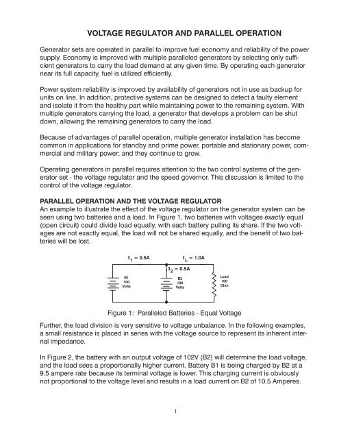
seen using two batteries and a load. In Figure 1, two batteries with voltages exactly equal<br />
(open circuit) could divide load equally, with each battery pulling its share. If the two voltages<br />
are not exactly equal, the load will not be shared equally, and the benefit of two batteries<br />
will be lost.<br />
Figure 1: <strong>Parallel</strong>ed Batteries - Equal <strong>Voltage</strong><br />
Further, the load division is very sensitive to voltage unbalance. In the following examples,<br />
a small resistance is placed in series with the voltage source to represent its inherent internal<br />
impedance.<br />
In Figure 2, the battery with an output voltage of 102V (B2) will determine the load voltage,<br />
and the load sees a proportionally higher current. Battery B1 is being charged by B2 at a<br />
9.5 ampere rate because its terminal voltage is lower. This charging current is obviously<br />
not proportional to the voltage level and results in a load current on B2 of 10.5 Amperes.<br />
1
Figure 2: <strong>Parallel</strong>ed Batteries - Unequal <strong>Voltage</strong><br />
In Figure 3, B1 is higher in voltage than B2 by 2 volts, causing B1 to supply the load and<br />
charge B2. In this scenario, B2 supplies 10.5A of load current.<br />
Figure 3: <strong>Parallel</strong>ed Batteries - Unequal <strong>Voltage</strong><br />
Please note that the voltage referred to in the diagrams is the open-circuit voltage. As<br />
soon as the batteries are paralleled, the voltage at the terminals of the batteries becomes<br />
identical.<br />
Two generators operating in parallel to supply a common load operate in a similar manner.<br />
If voltage (open-circuit) is exactly the same on both generators, they will divide the load<br />
equally between them. See Figure 4. Any small difference between generator voltages will<br />
result in unbalanced load division (Figure 5) or, in the extreme, circulating current (Figure 6).<br />
Figure 4: <strong>Parallel</strong>ed Generators - Figure 5: <strong>Parallel</strong>ed Generators -<br />
Balanced <strong>Voltage</strong> <strong>Voltage</strong> Unbalanced<br />
2
Figure 6: <strong>Parallel</strong>ed Generators - <strong>Voltage</strong> Unbalanced<br />
In practice, the precise matching of voltages is not possible. Some means must be provided<br />
to make load sharing between paralleled generators simple to control.<br />
Because circulating current or load unbalance described above is the result of voltage<br />
mismatch, you might look to the voltage regulator for some help. The regulator can provide<br />
this help using paralleling compensation circuits called reactive droop compensation or<br />
reactive crosscurrent compensation. Both types will be described in detail in later papers.<br />
The principle of operation of the reactive droop circuit, which is the simplest and most commonly<br />
used circuit, can be described by the curve in Figure 7.<br />
Figure 7: Reactive Droop Curves<br />
Using a regulator designed to maintain precise voltage regulation, a circuit is added that<br />
accepts a current signal from the generator’s output. This current signal is combined with<br />
the generator’s sensing voltage signal to develop a vector summed voltage proportional to<br />
reactive load.<br />
For example, if voltage decreases from 480 volts down to 458 voltage from no load to rated<br />
reactive (kvar) load, the voltage droop is -4.3%. If two generators are operated in parallel,<br />
with their droop curves set the same and their voltage setpoints adjusted to proportionally<br />
share the reactive load, any imbalance that would increase the load on one machine and<br />
decrease the load on the other would cause the droop circuits to change the voltage setpoints<br />
in a direction to bring the load back into balance. With droop compensation, the bus<br />
voltage will droop with changing reactive load.<br />
3
Figure 8: AVR with Droop<br />
By building this characteristic into the regulator of each generator operating in parallel,<br />
sharing of the load is controllable and uncomplicated.<br />
To parallel two generators, voltage on each machine should be matched prior to closing<br />
the breaker to minimize the current surge at breaker closing.<br />
Figure 9: <strong>Parallel</strong>ed Generators - Balanced <strong>Voltage</strong><br />
With voltages balanced and 100 Amperes load, each generator will supply its share of the<br />
load. If G2 voltage is increased, its output current will try to increase. This increase will<br />
cause a voltage droop, which counteracts the voltage increase. G1 will see its output current<br />
decrease, resulting in a droop circuit action to increase voltage. The result is a load<br />
balance control action that works to hold loading balanced when two or more generators<br />
are operating in parallel.<br />
WHY ContRol tWo VaRIaBleS?<br />
KW, KVaR, KVa<br />
In the dc analogy with batteries in parallel, only the voltage had to be controlled to allow<br />
for load sharing. When paralleling ac generators, torque and excitation both must be<br />
controlled properly. Torque applied to the generator must be controlled in order to divide<br />
real power (kilowatts); excitation to the generator must be controlled to divide the reactive<br />
power.<br />
4
Real power is work done by the electrical energy of the generator. This power is supplied<br />
by the prime mover in the form of torque. The generator converts mechanical torque to<br />
electrical energy. This energy is supplied to a load to be converted to the desired form of<br />
energy, such as heat, light, mechanical energy (motor), etc.<br />
Reactive power is that power required by loads with inductance or capacitance to store<br />
energy on each half cycle. In the example of Figure 10, the load is purely resistive, such as<br />
a heating element. Because no reactive power is required at any point on the sine wave,<br />
current is directly proportional to the voltage at that point. The real power can be calculated<br />
using Ohm’s Law.<br />
Figure 10: Resistive Load<br />
If an inductance (Figure 11) is connected to the generator output, the relationship between<br />
voltage and current is different. The inductor will not allow current to flow without first building<br />
up flux in its magnetic circuit. Thus, the current through the inductor is proportional to<br />
voltage, but the current lags the voltage by 90 electrical degrees (Figure 12).<br />
Figure 11: Inductive Load Figure 12: Current Lags <strong>Voltage</strong><br />
The capacitor, on the other hand, will not allow voltage across its terminals until some<br />
charge has been deposited on its plates (Figure 13). For this reason, the current must flow<br />
before a voltage can exist. Thus the capacitor current leads the voltage by 90 electrical<br />
degrees (Figure 14).<br />
Figure 13: Capacitive Load Figure 14: Current Leads <strong>Voltage</strong><br />
5
For a load containing all three elements in parallel (Figure 15), it is convenient to calculate<br />
the real or reactive power in each element separately. The Theory of Superposition (Figure<br />
16) allows the addition of the three separate calculations vectorially to determine the total<br />
load.<br />
Figure 15: Combined RLC Load<br />
Figure 16: Theory of Superposition<br />
A look at I 1 and I 2 indicates that these currents are always opposite in polarity. If the currents<br />
are equal, the net result is zero! For this reason, inductive loads are said to accept<br />
reactive power, while capacitors are said to supply reactive power. Power Factor correction<br />
capacitors use this principle to compensate for inductive loading. The reactive power flow<br />
is illustrated in Figure 17.<br />
6
Figure 17: LC Loads<br />
Thus, the reactive power, expressed in Vars, can be computed by:<br />
VARs = V 2<br />
X<br />
L<br />
- X<br />
C<br />
<strong>And</strong> the real power, expressed in watts, can be computed by:<br />
2<br />
V = Watts<br />
R<br />
A third parameter can be computed by using the voltage of the generator and the current<br />
I T in Figure 18. This parameter is known as “apparent power”.<br />
S = VI T (NO VECTORS)<br />
S = APPARENT POWER, VOLT-AMPERES<br />
Figure 18: Combined RLC Load<br />
These three parameters, real, reactive, and apparent power, are related. Knowing any two,<br />
the third can be calculated using the Pythagorean Theorem:<br />
Or they may be calculated using vector arithmetic (Figure 19):<br />
Figure 19A: Power Triangle Figure 19B: Apparent Power - kVA<br />
7
Metering is commonly provided to measure volts, amps and frequency for generators<br />
operating alone. For parallel application, monitoring current gives an indication of loading,<br />
but there is no indication of the type of current flow, making load sharing adjustment impossible.<br />
A meter to monitor real power in addition to current will enable power to be balanced<br />
by the governor adjustment, followed by balancing of current using voltage regulator<br />
adjustment. A better scheme adds an additional meter for reactive power, the Var meter.<br />
With a kW and Kvar meter on each generator, optimal adjustment of the governor and the<br />
voltage regulator is easily accomplished, and load sharing is easily monitored. Another<br />
metering option is the power factor meter, often used instead of the Kvar meter. Power factor<br />
is the ratio of real power to apparent power:<br />
P = REAL POWER, WATTS<br />
S = APPARENT POWER, VOLT-AMPERES Figure 19C: Reactive Power -<br />
Kvar<br />
Power factor, because it is affected by both real power and reactive power levels, is more<br />
difficult to interpret for monitoring load sharing performance. Providing good instrumentation<br />
is very helpful for operating systems of paralleled generators.<br />
tHe <strong>Voltage</strong> RegulatoR and PaRallel geneRatoR oPeRatIon<br />
The function of the voltage regulator is to provide precise regulated generator voltage at<br />
no load and with changing loads. When generators are connected together in parallel operation,<br />
a parallel compensation circuit is required to assist the voltage regulators in controlling<br />
the generator reactive loads.<br />
Reactive loads between generators can become unbalanced when the voltage regulator<br />
varies the excitation to the generator exciter field due to load changes, prime mover speed<br />
variation, thermal drift, etc. This change in excitation may cause large “circulating currents”<br />
to flow between generators (Figure 20).<br />
Figure 20: Circulating Currents<br />
This causes the generator with the higher field excitation to try and power the generator<br />
with the lower field excitation in an effort to force the generator to have the same output<br />
voltage as the generator with the higher excitation.<br />
8
The parallel compensation circuit will cause the voltage regulator to increase the field excitation<br />
on the generator with the lower field excitation and decrease the field excitation on<br />
the generator with the higher field excitation. By controlling the reactive load, the parallel<br />
compensation circuit can eliminate the undesired circulating currents.<br />
Figure 21: Equal Pressure - A Unequal Pressure - B<br />
An analogy of how one generator tries to power another generator with circulating currents<br />
can be compared to two water pipes of equal diameter feeding into one pipe. When the two<br />
water pipes have the same water pressure, both water pipes will be supplying the same<br />
amount of water to the common water pipe (Figure 21A). If one water pipe suddenly lost a<br />
small amount of pressure, the second water pipe would begin to supply more water to the<br />
common pipe to help maintain the water flow (Figure 21B). Also, because the water pressure<br />
in the second water pipe is now greater than the first water pipe, water will begin to<br />
flow from the second water pipe to the first water pipe in effort to force the water pressure to<br />
be the same as the second pipe.<br />
ReaCtIVe dRooP CoMPenSatIon and ReaCtIVe dRooP<br />
dIFFeRentIal CoMPenSatIon<br />
There are two forms of parallel compensation circuit. The most often used type of paralleling<br />
compensation is the parallel droop compensation or using the IEEE designation,<br />
reactive droop compensation. The other type is crosscurrent compensation or, again using<br />
IEEE terminology, reactive differential compensation.<br />
Figure 22: Reactive Droop Compensation<br />
9
When reactive droop compensation is used to parallel two or more generators, each<br />
parallel droop circuit is independent of the other (Figure 22). A typical parallel droop circuit<br />
is made up of a current transformer and paralleling module. The paralleling module consists<br />
of a burden resistor and a switch connected across the primary of a transformer (Figure<br />
23).<br />
Figure 23: <strong>Parallel</strong>ing Module<br />
A switch located on the primary of the transformer in the paralleling module is used to<br />
short the secondary of the current transformer and the burden resistor to allow the generator<br />
to operate independently of the paralleling generating system.<br />
The secondary of the current transformer is connected to the paralleling circuit. Connection<br />
to the paralleling circuit places a burden resistor across the output terminals of the<br />
current transformer (Figure 24). The secondary current of the current transformer induces<br />
a voltage across the burden resistor that is vectorially added to the line voltage to produce<br />
an error signal to the voltage regulator. <strong>Voltage</strong> across the burden resistor is proportional<br />
in magnitude and has the same phase as the line current through the primary of the current<br />
transformer.<br />
Figure 24: Burden Resistor<br />
10
Figure 25: Current Transformer Error Signal Development<br />
The error signal produced across the current transformer burden resistor must be applied<br />
so that when the load is a unity power factor load, no corrective signal will be produced<br />
and no excitation change will occur because of the load. By arranging the burden resistor<br />
voltage so that it will be 90 electrical degrees out of phase with the system voltage when<br />
the power factor of the load on the generator is unity, an appropriate error signal can be<br />
produced. Figure 25 shows the vector representation of system voltage and burden resistor<br />
voltage needed to produce the error signal.<br />
The three phase voltages (line to neutral), regardless of their internal connections, produce<br />
output voltages that are displaced from each other by 120 electrical degrees. By taking<br />
advantage of the phase displacement, it is possible to sense the system voltage from line<br />
to line and produce a line voltage that is displaced from the phase voltage by 30 electrical<br />
degrees. The voltage signal from the current transformer burden resistor at unity power<br />
factor (resistive loads) will be displaced by 90 electrical degrees from the system or line<br />
voltage (Figure 26A).<br />
11
Figure 26: Phase Displacement<br />
Under unity power factor, the vector diagram (Figure 26B) representation of the burden<br />
resistor voltage (V Phase B ) and the sensing voltage (V AC ) can be seen to be 90 electrical degrees<br />
apart. When a reactive load is applied to the generator, the burden resistor voltage<br />
arrow will swing either clockwise or counterclockwise depending upon the type of load,<br />
capacitive or inductive (Figure 26C).<br />
Figure 27: Vector Diagram of Capacitive Load<br />
If the generator load has a leading power factor (capacitive load), the vector diagram of<br />
the burden resistor voltage will rotate counterclockwise from its unity power factor position<br />
(Figure 27). The phase angle between the line voltage and burden resistor voltage will become<br />
more out of phase, which will decrease the regulator sensing voltage. The regulator<br />
will receive a smaller sensing signal and thus increase generator excitation.<br />
12
Figure 28: Vector Diagram of Inductive Load<br />
When the load is a lagging power factor or inductive load, the vector diagram of the burden<br />
resistor voltage will be rotated clockwise from its unity power factor position (Figure<br />
28). The phase angle between the line voltage and burden resistor voltage will become<br />
more in phase and the voltage sensing signal to the regulator will be increased. The regulator<br />
will receive the larger signal and respond by decreasing generator excitation.<br />
The parallel module will supply an error signal to the voltage regulator that will control<br />
the excitation level of the generator. When the generators are paralleled, the regulator<br />
responds to this small increase in sensing voltage by reducing excitation to the generator<br />
field, which will produce a droop in the generator output voltage.<br />
The amount a generator system will droop can be adjusted by the burden resistance and<br />
the current transformer ratio. A typical burden resistor has a resistance of one ohm and<br />
has an adjustable slide tap contact so that the voltage developed across the resistor can<br />
be varied. The amount of error signal sent to the voltage regulator is proportional to the<br />
magnitude of the voltage across the resistor and the vector angle of that voltage. The<br />
amount of voltage across the burden resistor is determined by the secondary or output<br />
current of the current transformer. Typical current transformers are designed for a 5 ampere<br />
secondary current with a 25VA maximum burden rating. Ohm’s Law (<strong>Voltage</strong> = Current<br />
X Resistance) will show the maximum voltage across the one ohm burden resistor to<br />
be 5 volts. It can then be seen that the relative magnitude of the voltage developed across<br />
the burden resistor with full load on the generator is typically 5 percent of the system output<br />
voltage (120/208-240/416-480/600) to minimize circulating currents.<br />
When generators are paralleled with reactive droop compensation, most generators are<br />
set to operate with maximum droop. The burden resistor is adjusted for maximum resistance<br />
or maximum voltage across the resistor. Allowing the generating system to operate<br />
at maximum droop allows for the best control of circulating currents. Setting the burden<br />
resistor for a system voltage droop of less than three percent may result in the regulator<br />
and paralleling circuit being unable to control circulating currents satisfactorily.<br />
<strong>Voltage</strong> regulators with single phase sensing provide approximately 8% maximum droop<br />
while three phase sensing regulators provide approximately 6% droop. Single phase sensing<br />
provides greater droop because the average value of the error signal is proportionally<br />
greater compared to the average value of the single phase sensing voltage than to the<br />
average value of the three phase sensing voltage. When generators are paralleled on the<br />
same bus and have different type sensing, care must be taken to compensate for sensing<br />
differences using the adjustable burden resistor.<br />
13
Since the burden resistance voltage is dependent on the line current of the generator<br />
through the current transformer, any changes in power factor due to the load will be reflected<br />
on the burden resistor voltage. Consequently, when a reactive lagging power factor<br />
load is increased, the bus voltage will droop by an increased amount. If a capacitive leading<br />
power factor load is increased, the bus voltage will increase. The magnitude of the<br />
change depends upon the magnitude of the load and power factor.<br />
In order to prevent the voltage from increasing or decreasing with the power factor of the<br />
load, another circuit can be used where the current transformers of the individual regulators<br />
are interconnected. Crosscurrent compensation (reactive differential compensation)<br />
allows operation in parallel without voltage droop caused by the error signal.<br />
Figure 29 shows two generators paralleled with reactive differential compensation. Interconnection<br />
of the current transformers can be seen. On generator number one, the current<br />
transformer (CT1) terminal with the polarity mark is connected to the current transformer<br />
(CT2) on generator number two at the terminal with no polarity mark. On generator number<br />
two, the current transformer (CT2) terminal with the polarity mark is connected to the<br />
current transformer (CT1) on generator number one at the terminal with no polarity mark.<br />
Figure 29: Two Generators <strong>Parallel</strong>ed with Reactive Differential Compensation<br />
Even though the voltage involved is ac, a better understanding of the operation of the<br />
closed crosscurrent loop can be obtained by using a dc voltage analysis. First of all, the<br />
polarity marks on the generator line and current transformer indicate the current direction.<br />
The line current always flows into the polarity mark on the generator line and the current<br />
flows out of the polarity mark on the current transformer (Figure 30).<br />
14
Figure 30: Burden Resistor<br />
The current leaving the polarity marks of the current transformer is divided into two current<br />
paths (Figure 29). One circuit path flows through the burden resistor in the paralleling<br />
module. The second circuit path flows through the crosscurrent loop. The current that<br />
flows in the crosscurrent loop will enter the burden resistor in the adjoining parallel circuit<br />
and will oppose the current through the burden resistor set up by the paralleling circuit’s<br />
own current transformer. The resulting current flow through the burden resistor in each<br />
paralleling circuit will be zero because the opposing currents will cancel each other out.<br />
Thus, there will be no voltage developed across the burden resistor and no droop associated<br />
with the line voltage.<br />
If one generator begins to export more reactive power than the other generator, the line<br />
current will increase and the current from the secondary of the current transformer will also<br />
increase. The result will cause a greater voltage across the burden resistor of the paralleling<br />
circuit, which will cause the voltage regulator to reduce the excitation in that particular<br />
generator, thus decreasing line current. An increase in current through the crosscurrent<br />
connect loop caused by the imbalance of the first generator will develop a voltage across<br />
the second generator’s paralleling burden resistor that is opposite in polarity to the normal<br />
voltage developed by the second generator’s own current transformer. Instead of causing<br />
a droop in line voltage, the opposite polarity will cause an increase in line voltage. The<br />
resulting increase in one generator and a decrease in the other generator will cause the<br />
parallel generating system to balance itself out.<br />
For the reactive differential compensation to perform properly, all of the paralleling current<br />
transformers on all of the generators delivering power to the bus must be connected into<br />
the crosscurrent loop. The current transformer connected in the loop must have the same<br />
ratios so that each current transformer supplies the same amount of current to properly<br />
cancel the voltage across the burden resistor. In the case where different size generators<br />
are paralleled, current transformer ratios must be changed to give approximately the same<br />
secondary current as the other current transformer(s). Otherwise, cancellation of the currents<br />
in the crosscurrent loop will not occur, and the imbalance of current will force the<br />
generators to have circulating currents between them.<br />
In addition to having the same current transformer ratios, all generators must have the<br />
same burden resistor setting in the voltage regulator paralleling circuit. Having the same<br />
burden resistor setting ensures that when an imbalance exists in the generators, the current<br />
that flows in the crosscurrent loop will setup a proportional voltage across each burden<br />
resistor that will balance the generator system’s reactive load.<br />
15
Figure 31: Reactive Differential Compensation Connection<br />
In order to perform properly, the crosscurrent loop must have all the generators tied into<br />
the loop. It is virtually impossible to parallel with an infinite bus (utility). If the crosscurrent<br />
connected generating system was paralleled with the utility outside the crosscurrent loop,<br />
a switch contact installed at any point in the loop may be opened, and all generators will<br />
operate in droop mode.<br />
For compliance with most safety codes, a ground connection is placed on the CT secondary.<br />
Only one ground can be installed on the loop, the current transformers will be shorted<br />
out (Figure 31).<br />
Some means of isolation between the regulator sensing circuit and the current transformer<br />
circuit must be used with crosscurrent compensation circuits. <strong>Basler</strong> regulators and paralleling<br />
circuits include isolation transformers used to effectively isolate the crosscurrent loop<br />
from the input voltage circuit of the regulator.<br />
tHe CuRRent tRanSFoRMeR unIt-PaRallel SWItCH<br />
A switch is placed on the secondary of the current transformer to short circuit the current<br />
transformer and the burden resistor, which will negate any signal to the generator. The<br />
switch in the “Unit” position allows the generator to operate independently of the parallel<br />
generating system without the effect of the droop circuit.<br />
16
When a generator is operating independently in a parallel droop system and the short<br />
circuit switch is not in the “Unit” position, the generator will have an unwanted droop in the<br />
generator output voltage. The same effect will happen in a crosscurrent system only the<br />
droop will be smaller because other burden resistors in series act as a voltage divider to<br />
decrease the amount of voltage proportionally.<br />
When generators are operating in a crosscurrent loop and one generator is taken out<br />
of parallel with the other generators to operate independently, the unit parallel switch is<br />
important to maintaining the stability of the remaining generators paralleled. If the non-paralleled<br />
generator is disconnected from the line with the current transformer and the burden<br />
resistor not shorted, the parallel system voltage will fluctuate. The generator not paralleled<br />
will be rotating at a different speed and frequency compared to the paralleled generators.<br />
The current through the burden resistor of the non-paralleled generator will have a<br />
constantly varying phase angle compared to the current through the paralleled generator<br />
burden resistors. The constantly changing phase angle across the burden resistor current<br />
of the non-paralleled generator will cause the non-paralleled regulator to alternately raise<br />
and lower the excitation of the non-paralleled generator. This will produce a small periodic<br />
change in excitation, which will increase and decrease that generator’s output voltage. The<br />
rate at which the voltage will fluctuate is equal to the difference in frequency from the nonparalleled<br />
generator and the paralleled generators.<br />
Figure 32: Unit - <strong>Parallel</strong> Switch<br />
If a unit-parallel switch is to be added externally to a paralleling circuit, attention must be<br />
made to the distance the switch is to be placed from the current transformer secondary<br />
terminals (Figure 32). If a considerable distance is required for connection of the switch,<br />
resistance from the wire to and from the switch might be great enough to allow some of<br />
the current to pass through the burden resistor. If a small current is allowed to flow through<br />
the burden resistor, an equally small voltage will be produced across the burden resistor<br />
and produce a small droop in the system voltage, if the system is paralleled with reactive<br />
droop compensation. If so, reactive differential compensation is used to produce an effect<br />
similar to that just described for the crosscurrent loop in the preceding paragraph. Connections<br />
to the shorting switch should be made as short as possible.<br />
17
Note: When operating with the reactive differential compensation circuit, it is desirable<br />
to have the unit parallel switch be an auxiliary contact on the main generator<br />
breaker. The auxiliary contact should be closed and the CT secondary<br />
shorted when the main generator breaker is open. The instant the main<br />
generator breaker closes connecting the generator in parallel, the auxiliary<br />
contact should open removing the short from the CT secondary allowing it<br />
to give the reactive load signal. This prevents any voltage droop from being<br />
introduced and eliminates the fluctuating voltage of the oncoming generator<br />
described earlier.<br />
Figure 33: Generator Phase Sequence/Current Transformer Polarity Relationship<br />
CuRRent tRanSFoRMeR PlaCeMent on unMaRKed PHaSeS<br />
As mentioned before, the current transformer can be connected to any phase of the generator<br />
as long as the system voltage is taken from the appropriate line voltage to maintain<br />
a 90 electrical degree phase difference with the burden resistor voltage. If it cannot be<br />
determined which generator lines are phase A, B, and C, the paralleling current transformer<br />
should be placed on the generator phase that does not supply sensing voltage to the<br />
regulator. If the regulator is set up with the generator for three phase sensing, the current<br />
transformer must be placed on the phase where the voltage regulator senses the B phase<br />
(Figure 33).<br />
The polarity connection of the current transformer will be the determining factor to whether<br />
the generators are paralleled correctly if the phase rotation is undeterminable. If the current<br />
transformer is connected incorrectly, the generator will not droop but will rise in voltage<br />
under lagging inductive load.<br />
If crosscurrent compensation is used to parallel the generators, it is recommended that<br />
the crosscurrent connecting loop be left open at one point until proper parallel option is<br />
achieved with the parallel droop compensation.<br />
18
CuRRent tRanSFoRMeR SeleCtIon<br />
Generators of different size KVA and line voltage have different line currents. When generators<br />
of different KVA are paralleled, current transformers used to parallel the generators<br />
must have correct current transformer ratios to provide nominal secondary current that is<br />
equal to other current transformers. A typical current transformer has a nominal 5 ampere<br />
secondary current with a maximum burden of 25VA. Obviously, to have a secondary current<br />
of 5 amperes, the primary current must be equal to the current rating of the primary.<br />
Matching current transformer ratios with line current to provide a nominal secondary current<br />
output from the current transformer is a detail that must not be overlooked. Table 1<br />
shows the design specifications of typical current transformers.<br />
When selecting a current transformer to step-down generator line current, if the line current<br />
falls between the current transformer primary ratings of two current transformers, the current<br />
transformer with the higher primary current rating should be selected. The reason for<br />
selection of the higher primary rating is to keep the current transformer within its maximum<br />
limits.<br />
The problem caused by using a current transformer with a lower primary rating is that<br />
the higher line current will force a higher secondary current than the nominal 5 amperes.<br />
A secondary current that exceeds the nominal 5 ampere value can cause the burden of<br />
the paralleling circuit to be greater than the maximum designed burden rating of the current<br />
transformer. Excessive current can cause transformers to reach saturation, which will<br />
change inductance values of the transformers. The resulting change in inductance can<br />
alter the phase angle of the signal that is sent to the voltage regulator for paralleling, causing<br />
an improper response from the regulator.<br />
On the other hand, it is also possible to select a current transformer with a primary rating<br />
that is too high. In such a case, the secondary current supplied to the paralleling circuit will<br />
be insufficient and paralleling operation can run uncontrolled or weak. Sometimes selecting<br />
a higher current transformer ratio and doubling the primary turns of the generator line<br />
can achieve a closer secondary current to the nominal 5 amperes.<br />
For best selection of a current transformer, finding a current transformer with a current<br />
transformer ratio that will provide the closest possible current to the nominal 5 amperes is<br />
suggested. Satisfactory parallel operation can usually be achieved if a minimum of three<br />
amperes at full load rated power factor is provided.<br />
Current transformer Requirements - droop<br />
• Instrument accuracy<br />
- accurate magnitude<br />
- accurate phase<br />
- may be shared<br />
• Ratio selected for minimum 3 amps (0.6 Amps)<br />
• Ratio selected for maximum 5 amps (1.0 Amps)<br />
19
Ct Requirements - Cross Current Compensation<br />
• Ratios equal for equal genset ratings<br />
• Ratios proportional if unequal ratings<br />
• Burden resistors same for all units<br />
• No groundings in each secondary<br />
Ct Burden Requirements<br />
• <strong>Basler</strong>’s AVRs have burdens between 0.2 and 1 ohm, 5 amp or 1 amp nominal<br />
current.<br />
• CT must have sufficient capacity to drive all loads, lead wire resistance.<br />
• Breaker aux contact and wire must be low in resistance to short CT effectively.<br />
Model<br />
Number<br />
Current<br />
Ratio<br />
(Amper<br />
es)<br />
ANSI<br />
Relay<br />
Class<br />
ANSI Metering Class (60HZ) Winding<br />
Resistance<br />
Ohms<br />
(25°C)<br />
BO.1 BO.2 BO.3 BO.4 BO.5<br />
0.6 0.6 1.2 2.4 -<br />
0.075<br />
0.3 0.6 1.2 1.2 2.4 0.093<br />
0.3 0.3 0.6 1.2 2.4 0.112<br />
0.3 0.3 0.3 0.6 1.2 0.149<br />
20<br />
Net<br />
Weight<br />
(lbs)<br />
Shipping<br />
Weight<br />
(lbs.)<br />
CT2 200:5 C10<br />
9.0 11.0<br />
250:5 C10<br />
CT3 300:5 C10<br />
9.0 11.0<br />
400:5 C20<br />
CT5 500:5 C20 0.3 0.3 0.3 0.6 1.2 0.186 9.0 11.0<br />
600:5 C20 0.3 0.3 0.3 0.3 0.6 0.224<br />
750:5 C20 0.3 0.3 0.3 0.3 0.3 0.280<br />
CT10 1000:5 - 0.3 0.3 0.3 1.2 - 0.184 2.8 4.8<br />
CT12 1200:5 - 0.3 0.3 0.3 0.6 1.2 0.245 2.9 4.9<br />
CT15 1500:5 - 0.3 0.3 0.3 0.3 0.6 0.275 3.1 5.1<br />
CT20 2000:5 - 0.3 0.3 0.3 0.3 0.3 0.34 3.3 5.3<br />
CT30 3000:5 - 0.3 0.3 0.3 0.3 0.3 0.52 3.7 5.7<br />
CT40 4000:5 - 0.3 0.3 0.3 0.3 0.3 0.70 3.9 5.9<br />
CT50 5000:5 - 0.3 0.3 0.3 0.3 0.3 1.25 5.5 7.5<br />
Table 1: <strong>Electric</strong>al Ratings<br />
PaRallelIng dIFFeRent SIZe geneRatoRS<br />
When generators of different kVA are paralleled, each generator will have a different line<br />
current. To parallel the different size generators, current transformers of different ratios will<br />
have to be used to step-down the different line currents to a standard nominal secondary<br />
current.<br />
For droop operation, the droop adjustment is used so that each generator droops a like<br />
amount at its rated load. Then, the generators can be paralleled and each generator can<br />
be adjusted to carry its proportional share of the reactive load.<br />
For generators paralleled with reactive differential compensation, equal currents are needed<br />
to cancel opposite currents so that no droop in the generating system is present. The<br />
unequal currents presented by the current transformers will force the cross-current loop<br />
to operate at an imbalance and maintain circulating currents. To decrease the imbalance<br />
of current through the cross-current loop, have all burden resistors set at maximum resistance.<br />
Then the burden resistor across the current transformer with the smallest secondary<br />
current should be adjusted for a smaller resistance so more current can flow through the
esistor. The burden resistor should only be adjusted for a small amount. Decreasing the<br />
burden resistance causes the response of the generator to be less sensitive to imbalances<br />
in the loop due to reactive loading. The burden resistor should only be adjusted a small<br />
amount so as to maintain proper control of circulating currents and also to decrease the<br />
current imbalance of the loop due to the current transformers.<br />
It must be pointed out that if current transformer secondary current among generators varies<br />
only by a few tenths of an ampere, conditions will be such that the imbalance injected<br />
into the cross-current loop or parallel droop circuits will be neglectable.<br />
PaRallelIng geneRatoRS<br />
To illustrate the considerations and paralleling equipment necessary to parallel generator<br />
sets, the two following examples of parallel three generator systems are presented.<br />
Two generating systems composed of three generators connected for parallel operation<br />
are illustrated in Figures 34 and 35. In Figure 35, the three generators are connected for<br />
parallel droop compensation; and in Figure 34, the three generators are connected for<br />
cross-current compensation. Both parallel generator systems have two 625 kVA generators<br />
with a kilowatt rating of 500 kW and one 125 kVA generator with a kilowatt rating of<br />
100 kW.<br />
21
Figure 34: Cross-Current Compensation Connections<br />
Figure 35: <strong>Parallel</strong> Droop Compensation Connections<br />
22
Each generator has a line-to-line voltage of 480 volts so the generators can be connected<br />
to a common bus. From the given information about the generators, the current for each<br />
generator is calculated from the apparent power (KVA) of the generator.<br />
kVA = 3 I L V L<br />
The current for the 625 kVA generators is 752 amperes, and the current for the 125 kVA<br />
generator is 150 amperes.<br />
The voltage regulators chosen for the generators operating with parallel droop compensation<br />
were selected to illustrate that voltage regulators do not necessarily have to be the<br />
same to operate with parallel droop. Both the 625 kVA generators are regulated with <strong>Basler</strong><br />
SSR regulators, and the 125 kVA generator is regulated with a generic voltage regulator.<br />
<strong>Basler</strong> voltage regulators and paralleling modules feature a built-in isolation transformer for<br />
cross-current compensation. The isolation transformer is necessary to prevent the sensing<br />
circuit of the regulators from being paralleled by the cross-current connections between<br />
generators.<br />
To determine how to add paralleling provision to a <strong>Basler</strong> regulator, Figure 35 can be used<br />
to make the selection. The SSR regulators that are used on the 625 kVA generators are<br />
equipped with paralleling provision as an option.<br />
The generic regulator has no paralleling provisions built-in so a <strong>Basler</strong> APM 300 paralleling<br />
module will be selected.<br />
The SSR voltage regulators equipped with paralleling provisions do not have a built-in unit/<br />
parallel switch to short out the current transformer and take the generator off-line or operate<br />
independent of the other generators. An external unit/parallel switch is added to the<br />
SSR voltage regulators.<br />
To further illustrate paralleling different size generators in the cross-current mode, Figure<br />
32 shows two <strong>Basler</strong> SSRs with a regulator of a different manufacturer or a <strong>Basler</strong> regulator<br />
with a different burden resistor value. To allow these generators to be connected in cross<br />
current, the burden resistors must match. This figure shows adding external resistors to<br />
the SSRs paralleling circuit to match burdens with the APM 300. We calculated this value<br />
using the following method.<br />
23
MetHod FoR deteRMInIng dRoPPIng ReSIStoR Value<br />
WHen ConneCtIng dISSIMIlaR RegulatoRS In<br />
CRoSS-CuRRent CoMPenSatIon ConFIguRatIon<br />
1. Start with the VA rating and current signal of each regulator and find its equivalent<br />
resistance.<br />
Example: SSR <strong>Regulator</strong>s: 10 VA, 5 Amps<br />
V = VA = 10 = 2 Volts; R = V = 2 = 0.4 ohms<br />
A 5 A 5<br />
Other regulator: 25 VA, 5 Amps<br />
V = VA = 25 = 5 Volts; R = V = 5 = 1.0 ohms<br />
A 5 A 5<br />
2. Take the regulator with the lowest VA rating (<strong>Voltage</strong> “V”) and determine the<br />
value of series resistance necessary to drop the applied voltage from the larger<br />
VA rating to that required by the present regulator. See figure below.<br />
Figure 36: <strong>Voltage</strong> <strong>Regulator</strong> with External Matching Resistor<br />
24
From previous example: 2V, 0.4 Ohms; 5V, 1.0 Ohms<br />
The required voltage is 2 volts but the supplied voltage is 5 volts; therefore, the series<br />
resistor should drop 3 volts:<br />
V Required = V Supplied R <strong>Regulator</strong><br />
R <strong>Regulator</strong> + R Series<br />
2 = 5 0.4<br />
0.4 + RSeries 2 (0.4 + R Series ) = 5 (0.4)<br />
0.4 + R Series = 1<br />
R Series = 0.6 Ohms<br />
The wattage of the series resistor can be calculated from:<br />
W = I 2 R<br />
W = 5 2 0.6 = 15 Watts<br />
Since we derate our resistors by 50%, the required wattage will be 30 watts. The next standard<br />
wattage value is 50 watts.<br />
Figure 37: <strong>Parallel</strong> Generator Setup<br />
25
tRouBleSHootIng PaRallelIng<br />
abnormal indications<br />
• Immediate increase in current<br />
• Difficult to adjust voltage adjust for null<br />
• Changing loads cause unbalance<br />
For immediate high current<br />
• Check paralleling in droop only<br />
• Verify that kW load is properly shared<br />
• Check SENSING connections to AVR<br />
• CT in correct phase??<br />
• Reverse CT secondary polarity<br />
• Try to parallel again<br />
• If all above is OK, try to close cross current loop<br />
Correct Ct polarity??<br />
• Place CT on correct phase<br />
- No sensing connection, or<br />
- E2 sensing connection<br />
• If CT is on correct phase, polarity is:<br />
- Correct, and closing breaker works okay, or<br />
- Reversed, and closing breaker causes immediate high current<br />
• Wrong phase, possibilities MULTIPLY!!!<br />
Finding the problems<br />
• Check for small voltage across droop input. CT may be shorted somewhere.<br />
• Check droop adjust. Max or min??<br />
• Check polarity marks on PTs with small battery and voltmeter<br />
• Verify PT connections, CT in correct phase<br />
Figure 38: Potential Transformer Polarity Check<br />
26
Further testing<br />
• OK to parallel without any droop on one machine, with careful attention.<br />
• Check to see that two machines can share load if only one of the droop CTs is<br />
not shorted.<br />
• If loading is possible, check for direction of droop by increasing drooping AVR<br />
voltage adjust.<br />
another test<br />
• Connect oscilloscope to E1 and E3, channel 1<br />
• Connect channel 2 to Droop input, 1 and 2<br />
• With some resistive load current, observe 90° phase shift from voltage to current<br />
Figure 39: AVR with Droop<br />
27
If you have any questions or need<br />
additional information, please contact<br />
<strong>Basler</strong> <strong>Electric</strong> Company<br />
12570 State Route 143, Highland, Illinois U.S.A. 62249-1074<br />
Tel +1 618.654.2341 Fax +1 618.654.2351<br />
e-mail: info@basler.com<br />
P.A.E. Les Pins, 67319 Wasselonne Cedex FRANCE<br />
Tel +33 3.88.87.1010 Fax +33 3.88.87.0808<br />
e-mail: franceinfo@basler.com<br />
No. 59 Heshun Road Loufeng District (N),<br />
Suzhou Industrial Park, 215122, Suzhou, P.R.China<br />
Tel +86(0)512 8227 2888 Fax +86(0)512 8227 2887<br />
e-mail: chinainfo@basler.com<br />
111 North Bridge Rd #15-06 Peninsula Plaza Singapore 179098<br />
Tel +65 68.44.6445 Fax +65 65.68.44.8902<br />
e-mail: singaporeinfo@basler.com